Embed Size (px)
Citation preview
Owner’s Manual
ME-BMKBattery Monitor Kit
ii ©2007 Magnum Energy Inc.
Disclaimer of Liability
Since the use of this manual and the conditions or methods of installation, operation, use and maintenance of the ME-BMK is beyond the control of Magnum Energy Inc., this company does not assume responsibility and expressly disclaims liability for loss, damage or expense, whether direct, indirect, consequential or incidental, arising out of or anyway connected with such installation, operation, use, or maintenance.Due to continuous improvements and product updates, the images shown in this manual may not exactly match the unit purchased.
Restrictions on Use
The ME-BMK shall not be used in connection with life support systems, life saving or other medical equipment or devices. Using the ME-BMK with this particular equipment is at your own risk.
IMPORTANT PRODUCT SAFETY INSTRUCTIONS
This manual contains important safety instructions that must be followed during the installation and operation of this product. Read all instructions and safety information contained in this manual before installing or using this product.
WARNINGS:
• All electrical work must be performed in accordance with local, state and federal electrical codes.
• This product is designed for indoor / compartment installation. It must not be exposed to rain, snow, moisture or liquids of any type.
• Use insulated tools to reduce the chance of electrical shock or accidental short circuits.
• Remove all jewelry such as rings, watches, bracelets, etc., when installing or performing maintenance on the ME-BMK and inverter system.
• Always disconnect the batteries or energy source prior to installing or per-forming maintenance on the ME-BMK and inverter system. Live power may be present at more than one point since an inverter utilizes both batteries and AC. Turning off the inverter may not reduce this risk. As long as AC power is connected, it will pass thru the inverter regardless of the power switch on the inverter or the ON/OFF INVERTER pushbutton on the remote.
Safety Symbols
To reduce the risk of electrical shock, fi re, or other safety hazard, the fol-lowing safety symbols have been placed throughout this manual to indicate dangerous and important safety instructions.
WARNING: This symbol indicates that failure to take a specifi ed action could result in physical harm to the user.
CAUTION: This symbol indicates that failure to take a specifi ed ac-tion could result in damage to the equipment.
Info: This symbol indicates information that emphasizes or supple-ments important points of the main text.
©2007 Magnum Energy Inc. iii
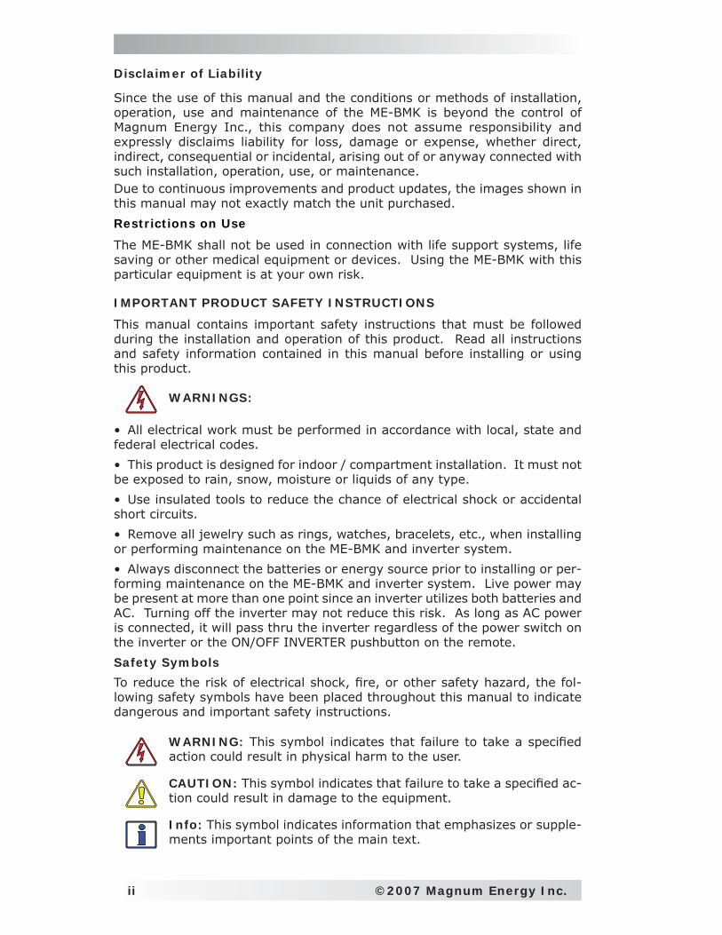
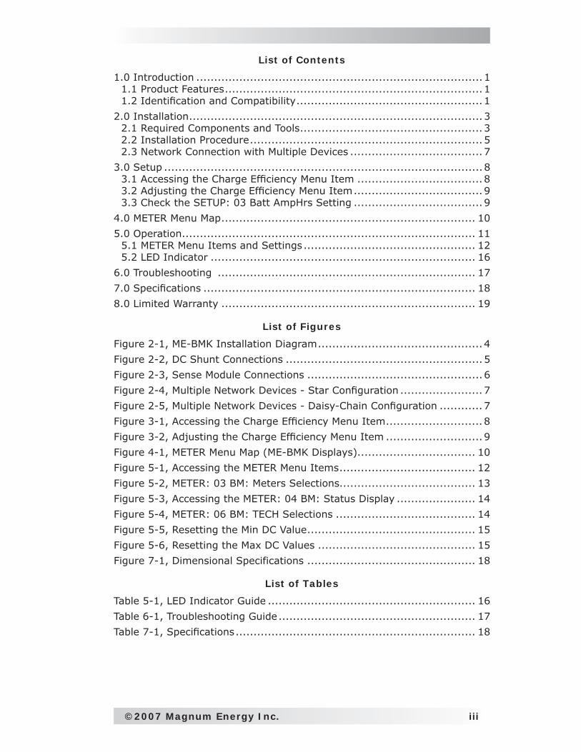
List of Contents
1.0 Introduction ................................................................................11.1 Product Features ........................................................................11.2 Identifi cation and Compatibility ....................................................1
2.0 Installation ..................................................................................32.1 Required Components and Tools ...................................................32.2 Installation Procedure .................................................................52.3 Network Connection with Multiple Devices .....................................7
3.0 Setup .........................................................................................83.1 Accessing the Charge Effi ciency Menu Item ...................................83.2 Adjusting the Charge Effi ciency Menu Item ....................................93.3 Check the SETUP: 03 Batt AmpHrs Setting ....................................9
4.0 METER Menu Map ....................................................................... 10
5.0 Operation .................................................................................. 115.1 METER Menu Items and Settings ................................................ 125.2 LED Indicator .......................................................................... 16
6.0 Troubleshooting ........................................................................ 17
7.0 Specifi cations ............................................................................ 18
8.0 Limited Warranty ....................................................................... 19
List of Figures
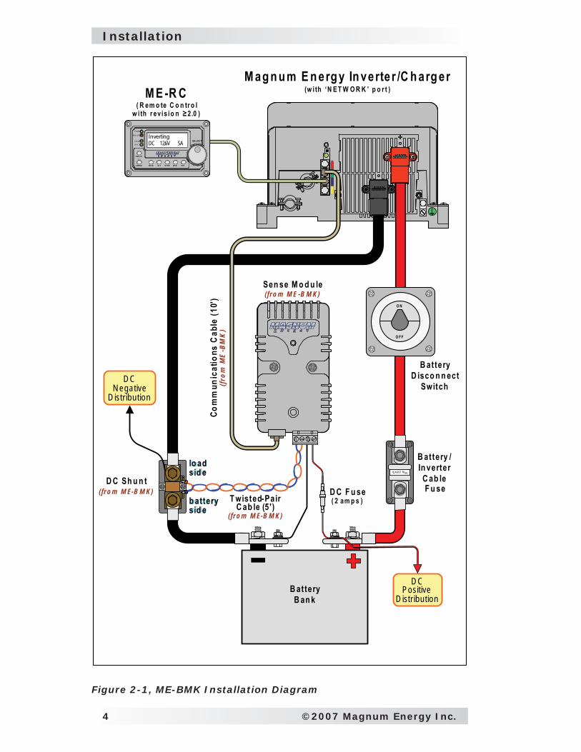
Figure 2-1, ME-BMK Installation Diagram ..............................................4
Figure 2-2, DC Shunt Connections .......................................................5
Figure 2-3, Sense Module Connections .................................................6
Figure 2-4, Multiple Network Devices - Star Confi guration .......................7
Figure 2-5, Multiple Network Devices - Daisy-Chain Confi guration ............7
Figure 3-1, Accessing the Charge Effi ciency Menu Item ...........................8
Figure 3-2, Adjusting the Charge Effi ciency Menu Item ...........................9
Figure 4-1, METER Menu Map (ME-BMK Displays)................................. 10
Figure 5-1, Accessing the METER Menu Items ...................................... 12
Figure 5-2, METER: 03 BM: Meters Selections...................................... 13
Figure 5-3, Accessing the METER: 04 BM: Status Display ...................... 14
Figure 5-4, METER: 06 BM: TECH Selections ....................................... 14
Figure 5-5, Resetting the Min DC Value ............................................... 15
Figure 5-6, Resetting the Max DC Values ............................................ 15
Figure 7-1, Dimensional Specifications ............................................... 18
List of Tables
Table 5-1, LED Indicator Guide .......................................................... 16
Table 6-1, Troubleshooting Guide ....................................................... 17
Table 7-1, Specifi cations ................................................................... 18

iv ©2007 Magnum Energy Inc.
this page left blank
©2007 Magnum Energy Inc. 1
Introduction
1.0 Introduction
The ME-BMK is a single battery bank amp-hour meter that monitors and pro-vides important information about the condition of the battery. This informa-tion will let you know how much energy you have available and let you plan your electrical usage to ensure the battery is not being over-discharged.
The ME-BMK is easy to install and is designed to be networked with a Magnum Energy inverter/charger using the ME-RC remote to display the information about your battery bank.
1.1 Product Features
• Compatible with 12, 24 or 48 volt systems• One adjustable setting - very easy setup• All battery meter and Magnum inverter/charger set-up and moni-
toring features in a single convenient display – doesn’t require multiple displays for inverter and battery system information
• Displays reliable and pertinent information; such as:Battery State of ChargeBattery VoltageBattery Current
• Auto-detecting input voltage• Temperature and battery bank capacity automatically compensated
and coordinated between inverter and battery monitor• Precision 500A/50mv DC shunt (included in ME-BMK) • Automatic effi ciency detection
1.2 Identifi cation and Compatibility
The ME-BMK is compatible with all Magnum inverter/chargers provided with a ‘Magnum Net’ or ‘Network’ port (i.e. ME, MS and RD Series). The ME-BMK requires a ME-RC remote display with revision 2.0 or higher to access the available settings and features of the ME-BMK.
Info: You can view the ME-RC revision level when you fi rst power-up the remote or by pushing the TECH button and accessing the 02 Revisions menu.
If the ME-RC remote revision is not 2.0 or higher, refer to one of the two op-tions below to obtain the required revision.
1) If the ME-BMK is being installed at the same time as a newly purchased Magnum Inverter and ME-RC remote system; contact your Magnum Energy dealer to obtain the ME-RC with revision 2.0 or higher.
2) If the ME-BMK is being installed into an installation with a previously installed Magnum inverter and ME-RC remote system; contact Magnum Energy about ME-RC upgrade options.
•••
2 ©2007 Magnum Energy Inc.
Introduction
Why should I use the Magnum Battery Monitor? To ensure your batteries perform satisfactory and have a long life, they need to be properly maintained and charged. There are several devices that help to determine if the batteries are being fully charged, they are:
• DC Voltmeter: An accurate DC voltmeter can be used to measure the Open Circuit Voltage (OCV) across the battery terminals and compare the readings with the OCV values from the battery manufacturer. A DC voltmeter is the least costly, but is also the least accurate and requires the batteries to be at “rest”. This “rest” requirement means the volt-age measurement should only be done when there is no current moving through the battery for a long period of time (most experts say a mini-mum of 1 hour). Using a DC voltmeter when the batteries are at “rest” is usually impractical, because the batteries are usually always powering loads or being charged.• Hydrometer: A good hydrometer can be used to measure the concen-tration of battery electrolyte in each individual cell and compare these readings with the specifi c gravity values from the battery manufacturer. A hydrometer is very accurate, but can be time-consuming and becomes unpleasant when working with sulfuric acid. A hydrometer will not work with sealed batteries.• Amp-hour Meter: An amp-hour meter is an electronic measuring device that uses a precision shunt to calculate the amp-hours going in (charging) and coming out (discharging) a battery. This meter tracks the amp-hour usage and compares it against the amp-hour capacity of the battery to determine its charge condition. Calculating Amp-Hours in vs. Amp-Hours out is fairly accurate, is easily displayed, but doesn’t provide an accurate State Of Charge under all charge and discharge conditions.
Theses devices have advantages and disadvantages based on accuracy and ease of use. The Magnum Energy Battery Monitor combines the advantages of these devices with additional information such as monitoring battery tem-perature and calculating battery effi ciencies to provide an easy and accurate means to determine the battery’s State of Charge (SOC) condition. Therefore, if the battery’s State of Charge is easily determined and accurate, the more likely you will attempt to keep the batteries charged and enjoy your battery system performance.
What is the difference between Amps and Amp-Hrs? Amps indicate the fl ow of current going in or out of the battery. Amp-hours indicate the amount of current returned to or removed from the battery. Amp-hrs are a common rating used to calculate the battery’s available capacity. For example, if a constant 3 amperes where removed from a 100 AH battery each hour, the battery bank’s capacity would be 94 AH after 2 hours (6 amp-hours less).
To help understand the difference, imagine the battery bank is equivalent to a water tank. When viewing the amps display, it would be similar to watching a water gauge. You can see that the water is fl owing a little or a lot, but this doesn’t indicate how much water is left. When viewing the State Of Charge (SOC) display, it would be similar to viewing the water tank’s level indicator, which tells you how much water is left in the tank.
For example: If you have a 10 gallon water tank and you remove water from the tank with a one gallon bucket. The water level indicator would show the available water has decreased by 10%; leaving 90% of the water still available. If this was a battery bank, then you would know that 10 percent of the battery’s capacity has been used and its State of Charge (SOC) is now 90%.
©2007 Magnum Energy Inc. 3
Installation
2.0 Installation
Before installing the ME-BMK, read this entire section to be aware of all as-pects of the installation; then you can thoroughly plan the details to ensure the overall system requirements are accomplished.
To assist you in planning and designing your installation; you should review the basic system diagram shown in Figure 2-1. If another network device besides the ME-BMK is to be installed, refer to section 2.3 to determine your specifi c network confi guration.
Info: Installations should be performed by qualifi ed personnel, such as a licensed or certifi ed electrician. It is the installer’s responsibility to determine which safety codes apply and to ensure that all appli-cable installation requirements are followed. Applicable installation codes vary depending on the specifi c location and application.
Info: Review the “Important Product Safety Information” on the front inside cover page before any installation.
Review the following guidelines prior to performing the Installation:
• The ME-BMK sense module is connected to the inverter by a 10’ communi-cations cable and to the DC shunt using a 5’ twisted-pair signal wire. Before installing the ME-BMK Sense module and connecting any wires, determine: 1) the communications cable route throughout the home or vehicle/boat to the inverter, and 2) the twisted-pair signal wire route to the ME-BMK shunt.
Info: The communications cable may be extended beyond the supplied 10’; but to ensure voltage accuracy, do not extend the 5’ twisted-pair wire used between the DC shunt and sense module.
Info: For information on the size of the battery cable and overcur-rent protection device to be used in the installation, refer to the inverter’s owner’s manual.
2.1 Required Components and Tools
2.1.1 List of supplied components in the ME-BMK (see fi gure 2-1):• Installation and Operation manual• Sense Module (with two #8 x 3/4” Phillips mounting screws)• 500A/50mv DC Shunt (with two #8 x 3/4” Phillips mounting screws)*• 10ft Communications cable• 5ft Twisted-pair (blue and orange color) signal wires
2.1.2 List of other Required Equipment and Materials:
• Magnum Inverter with network port (ME, MS or RD Series)• ME-RC (Magnum ME-RC remote display with revision ≥ 2.0)• Batteries (with appropriately sized cables)• Short (~18”) battery cable (to connect shunt to battery negative)• In-line fuse holder (with 2-amp DC fuse)• DC Breaker (or DC fuse and disconnect) for inverter• Phone-splitter (if using multiple network devices)
2.1.3 Tools Required to install the ME-BMK:• Flat-blade screwdrivers (1/4” and 1/8” blades)• #2 Phillips screwdriver• 9/16” open-end wrench or adjustable crescent wrench
4 ©2007 Magnum Energy Inc.
Installation
M E -R C( R em o te C o n tr o l
w i th r ev is io n ≥ 2 .0 )
M ag n u m E n erg y In verter /C h arg er(w i th ‘N E T W O R K ’ p o r t )
B atteryB an k
D C Sh u n t(fr o m M E-B M K)
B attery D isco n n ect
Switch
B attery /In verterC ab leF u seD C F u se
( 2 am p s )
D C N egative
D istr ibution
D C Positive
D istr ibution
Sen se M o d u le(fr o m M E -B M K)
Com
mun
icat
ions
Cab
le (1
0')
(from
ME
-BM
K)
T wisted-Pair C ab le (5 ')
(fr o m M E-B M K)
InvertingDC 12.6V 5A S E L E CT
TECHAG S M ETER SETUPSHO REI NVERTER
CHARG ER
I N V
C H G
FA U LT
P W R
O N /O F F
O N /O F F
CLASS T FUSE
O FF
O N
ba tte ry s ideb attery sid e
loa ds idelo adsid e
Figure 2-1, ME-BMK Installation Diagram
©2007 Magnum Energy Inc. 5
Installation
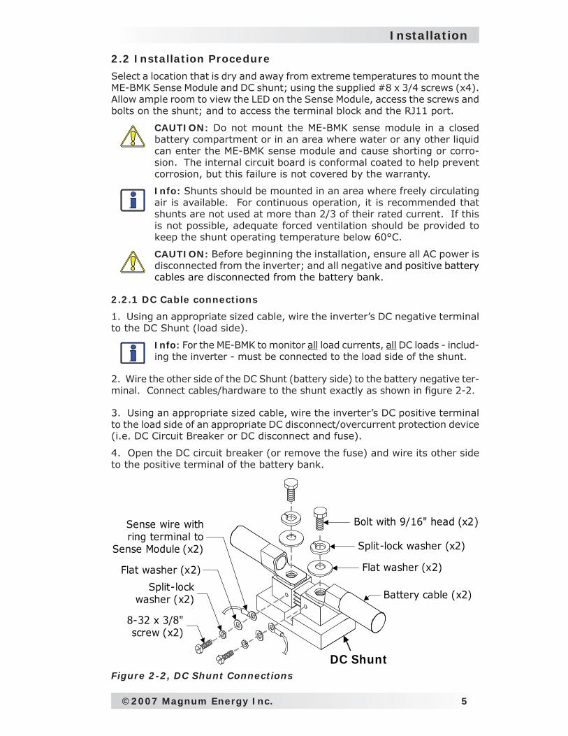
2.2 Installation Procedure
Select a location that is dry and away from extreme temperatures to mount the ME-BMK Sense Module and DC shunt; using the supplied #8 x 3/4 screws (x4). Allow ample room to view the LED on the Sense Module, access the screws and bolts on the shunt; and to access the terminal block and the RJ11 port.
CAUTION: Do not mount the ME-BMK sense module in a closed battery compartment or in an area where water or any other liquid can enter the ME-BMK sense module and cause shorting or corro-sion. The internal circuit board is conformal coated to help prevent corrosion, but this failure is not covered by the warranty.
Info: Shunts should be mounted in an area where freely circulating air is available. For continuous operation, it is recommended that shunts are not used at more than 2/3 of their rated current. If this is not possible, adequate forced ventilation should be provided to keep the shunt operating temperature below 60°C.
CAUTION: Before beginning the installation, ensure all AC power is disconnected from the inverter; and all negative and positive battery cables are disconnected from the battery bank.
2.2.1 DC Cable connections
1. Using an appropriate sized cable, wire the inverter’s DC negative terminal to the DC Shunt (load side).
Info: For the ME-BMK to monitor all load currents, all DC loads - includ-ing the inverter - must be connected to the load side of the shunt.
2. Wire the other side of the DC Shunt (battery side) to the battery negative ter-minal. Connect cables/hardware to the shunt exactly as shown in fi gure 2-2.
3. Using an appropriate sized cable, wire the inverter’s DC positive terminal to the load side of an appropriate DC disconnect/overcurrent protection device (i.e. DC Circuit Breaker or DC disconnect and fuse).
4. Open the DC circuit breaker (or remove the fuse) and wire its other side to the positive terminal of the battery bank.
Battery cable (x2)
Flat washer (x2)
Split-lock washer (x2)
Bolt with 9/16" head (x2)
8-32 x 3/8" screw (x2)
Flat washer (x2)
Sense wire with ring terminal to
Sense Module (x2)
Split-lockwasher (x2)
DC ShuntFigure 2-2, DC Shunt Connections
6 ©2007 Magnum Energy Inc.
Installation
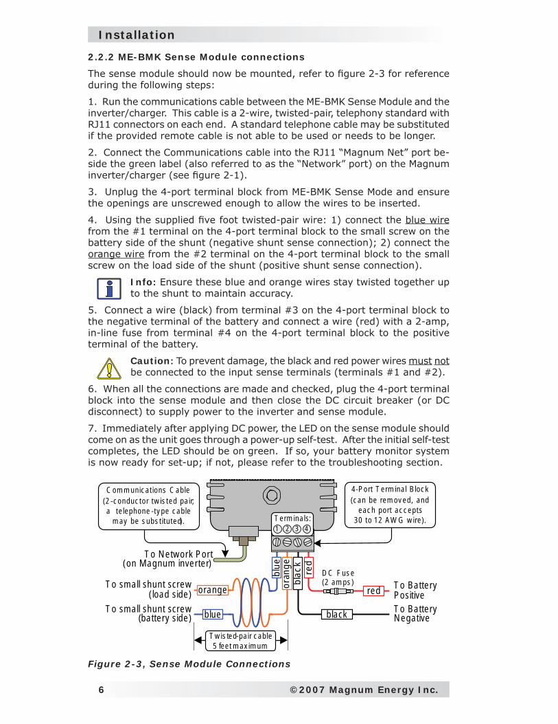
2.2.2 ME-BMK Sense Module connections
The sense module should now be mounted, refer to fi gure 2-3 for reference during the following steps:
1. Run the communications cable between the ME-BMK Sense Module and the inverter/charger. This cable is a 2-wire, twisted-pair, telephony standard with RJ11 connectors on each end. A standard telephone cable may be substituted if the provided remote cable is not able to be used or needs to be longer.
2. Connect the Communications cable into the RJ11 “Magnum Net” port be-side the green label (also referred to as the “Network” port) on the Magnum inverter/charger (see fi gure 2-1).
3. Unplug the 4-port terminal block from ME-BMK Sense Mode and ensure the openings are unscrewed enough to allow the wires to be inserted.
4. Using the supplied fi ve foot twisted-pair wire: 1) connect the blue wire from the #1 terminal on the 4-port terminal block to the small screw on the battery side of the shunt (negative shunt sense connection); 2) connect the orange wire from the #2 terminal on the 4-port terminal block to the small screw on the load side of the shunt (positive shunt sense connection).
Info: Ensure these blue and orange wires stay twisted together up to the shunt to maintain accuracy.
5. Connect a wire (black) from terminal #3 on the 4-port terminal block to the negative terminal of the battery and connect a wire (red) with a 2-amp, in-line fuse from terminal #4 on the 4-port terminal block to the positive terminal of the battery.
Caution: To prevent damage, the black and red power wires must not be connected to the input sense terminals (terminals #1 and #2).
6. When all the connections are made and checked, plug the 4-port terminal block into the sense module and then close the DC circuit breaker (or DC disconnect) to supply power to the inverter and sense module.
7. Immediately after applying DC power, the LED on the sense module should come on as the unit goes through a power-up self-test. After the initial self-test completes, the LED should be on green. If so, your battery monitor system is now ready for set-up; if not, please refer to the troubleshooting section.
D C F us e (2 am ps ) T o Battery
PositiveT o Battery N egative
T o N etw ork Por t(on M agnum inver ter)
T o sm all shunt screw(battery side)
T o sm all shunt screw( load side)
oran
gebl
ue
blac
kre
d
C om m unic a t ions C ab le(2 -c onduc tor tw is ted pa ir; a t e lephone -ty pe c ab le
m ay be s ubs t it u ted).
4 -P ort T erm ina l B loc k (c an be rem ov ed, and
eac h port ac c epts30 to 12 A W G w ire ).
b lack
red
T erm ina ls:1 2 43
T w is ted-pa ir c ab le 5 fee t m ax im um
orange
blue
Figure 2-3, Sense Module Connections
©2007 Magnum Energy Inc. 7
Installation
InvertingDC 12.6V 5A S E L E CT
TECHAG S M ETER SETUPSHO REI NVERTER
CHARG ER
I N V
C H G
FA U LT
P W R
O N / O F F
O N / O F F
M E -A GS (1 st dev ice)M E -R C
M agnum Inve rte r /cha rge r
P honesplitter
M E -B M K (2 n d dev ice )
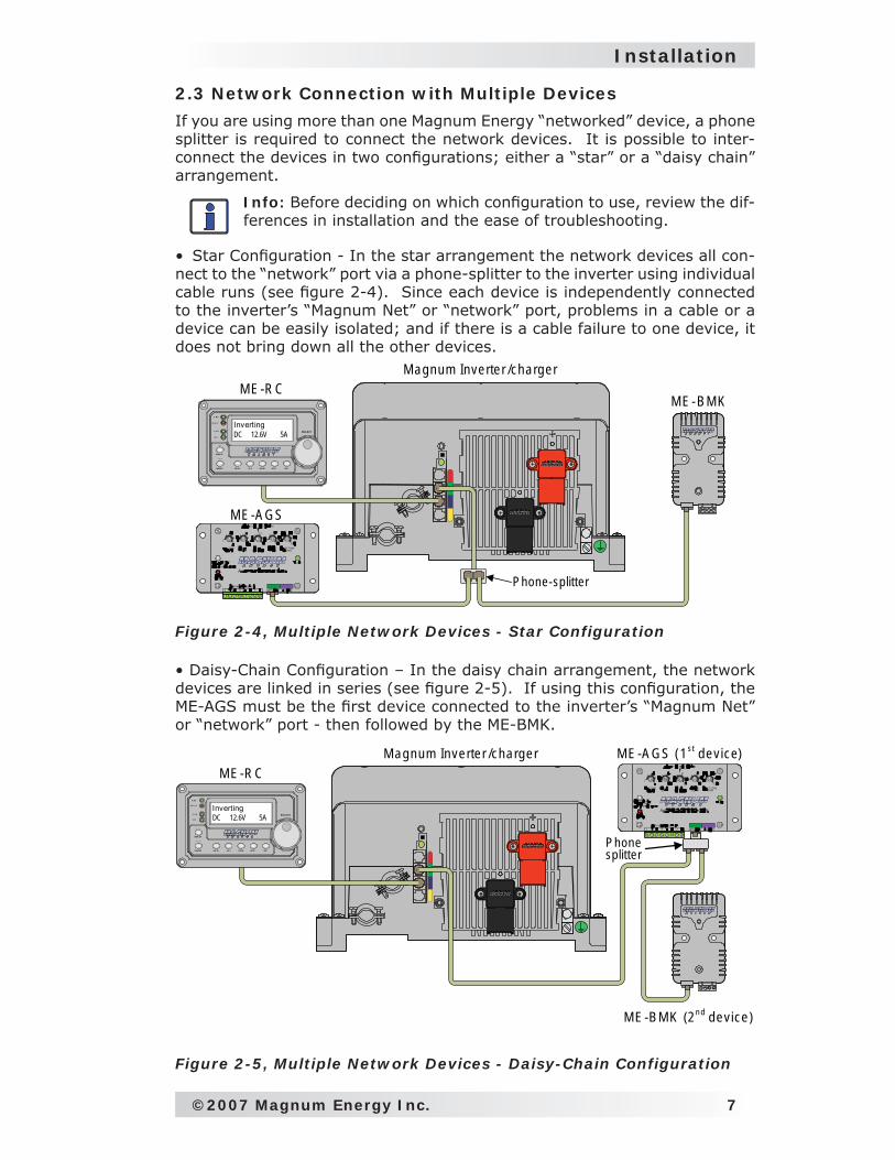
2.3 Network Connection with Multiple Devices
If you are using more than one Magnum Energy “networked” device, a phone splitter is required to connect the network devices. It is possible to inter-connect the devices in two confi gurations; either a “star” or a “daisy chain” arrangement.
Info: Before deciding on which confi guration to use, review the dif-ferences in installation and the ease of troubleshooting.
• Star Confi guration - In the star arrangement the network devices all con-nect to the “network” port via a phone-splitter to the inverter using individual cable runs (see fi gure 2-4). Since each device is independently connected to the inverter’s “Magnum Net” or “network” port, problems in a cable or a device can be easily isolated; and if there is a cable failure to one device, it does not bring down all the other devices.
Figure 2-5, Multiple Network Devices - Daisy-Chain Configuration
InvertingDC 12.6V 5A S E L E CT
TECHAG S M ETER SETUPSHO REI NVERTER
CHARG ER
I N V
C H G
FA U LT
P W R
O N /O F F
O N /O F F
M E -B M KM E -R C
M E -A GS
M agnum Inve rte r /cha rge r
P hone-splitter
• Daisy-Chain Confi guration – In the daisy chain arrangement, the network devices are linked in series (see fi gure 2-5). If using this confi guration, the ME-AGS must be the fi rst device connected to the inverter’s “Magnum Net” or “network” port - then followed by the ME-BMK.
Figure 2-4, Multiple Network Devices - Star Configuration
8 ©2007 Magnum Energy Inc.
Setup
3.0 Setup
This section provides information on the charge effi ciency setting and shows you how to access/adjust this setting. Normally the ME-BMK Battery Monitor (BM) automatically calculates the battery’s effi ciency, however you may want to manually set the effi ciency.
Info: The factory default setting is Chg Eff: Auto, this setting al-lows the charging effi ciency to be automatically calculated. In most circumstances, the “Auto” setting will determine the best charge effi ciency.
CAUTION: If you do not know your battery’s charging effi ciency, leave this setting at the factory default setting, if this setting is manually set and incorrect, the state-of-charge information would be more inaccurate with every charge.
What is Charge Effi ciency? When a certain amount of energy is removed or discharged from the battery, this removed energy will need to be returned to keep the batteries at a 100% state of charge. As batteries are being charged, they lose energy; either in the form of heat or while gassing. This loss of energy while charging means the battery will not be fully charged if you only return the current that was removed. To compensate for the batter-ies ineffi ciencies while charging, a charge effi ciency setting is provided. The charge effi ciency setting compensates the AH I/O (AmpHrs In/Out) reading by ensuring the amphrs returned to the battery are greater than the amp-hours removed.
For example, if your AH I/O display reads 000 and you begin powering a 25 amp load for two hours, the display will show -050. This indicates that you have discharged 50 amp-hrs (2 x 25) from the battery. If the charge effi ciency setting is set to 95%, then as you begin charging and return 50 amp-hrs, the AH I/O reading will be less than zero, indicating that the amp-hours removed have not been fully returned. The 95% charge effi ciency setting requires 52.5 amp-hours (50/95) to be returned before the AH I/O returns to 0.
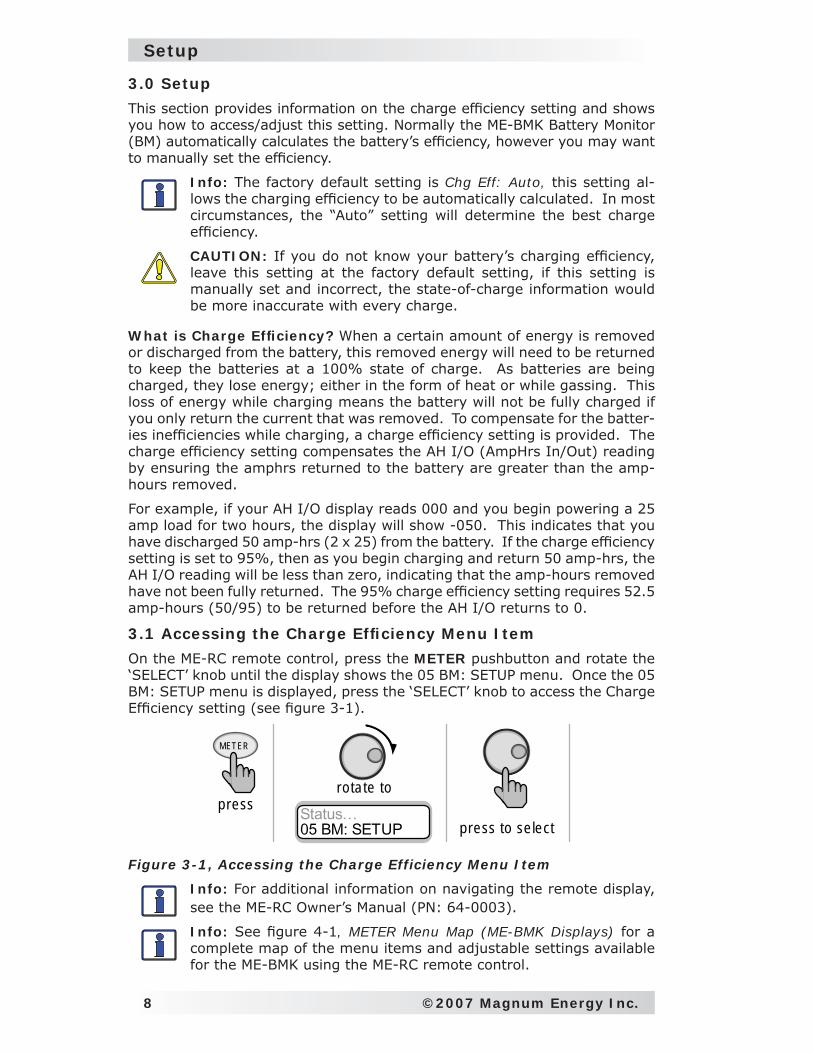
3.1 Accessing the Charge Effi ciency Menu Item
On the ME-RC remote control, press the METER pushbutton and rotate the ‘SELECT’ knob until the display shows the 05 BM: SETUP menu. Once the 05 BM: SETUP menu is displayed, press the ‘SELECT’ knob to access the Charge Effi ciency setting (see fi gure 3-1).
Figure 3-1, Accessing the Charge Efficiency Menu Item
Info: For additional information on navigating the remote display, see the ME-RC Owner’s Manual (PN: 64-0003).
Info: See fi gure 4-1, METER Menu Map (ME-BMK Displays) for a complete map of the menu items and adjustable settings available for the ME-BMK using the ME-RC remote control.
METER
press Status…05 BM: SETUP
ro tate to
press to se lect
©2007 Magnum Energy Inc. 9
Setup
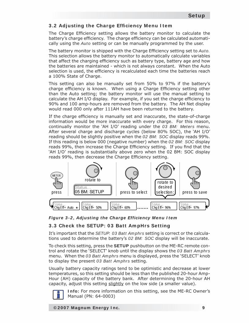
3.2 Adjusting the Charge Effi ciency Menu Item
The Charge Effi ciency setting allows the battery monitor to calculate the battery’s charge effi ciency. The charge effi ciency can be calculated automati-cally using the Auto setting or can be manually programmed by the user.
The battery monitor is shipped with the Charge Effi ciency setting set to Auto. This selection allows the battery monitor to automatically calculate variables that affect the charging effi ciency such as battery type, battery age and how the batteries are maintained - which is not always constant. When the Auto selection is used, the effi ciency is recalculated each time the batteries reach a 100% State of Charge.
This setting can also be manually set from 50% to 97% if the battery’s charge effi ciency is known. When using a Charge Effi ciency setting other than the Auto setting; the battery monitor will use the manual setting to calculate the AH I/O display. For example, if you set the charge effi ciency to 90% and 100 amp-hours are removed from the battery. The AH Net display would read 000 only after 111AH have been returned to the battery.
If the charge effi ciency is manually set and inaccurate, the state-of-charge information would be more inaccurate with every charge. For this reason, continually monitor the ‘AH I/O’ reading under the 03 BM: Meters menu. After several charge and discharge cycles (below 80% SOC), the ‘AH I/O’ reading should be slightly positive when the 02 BM: SOC display reads 99%. If this reading is below 000 (negative number) when the 02 BM: SOC display reads 99%, then increase the Charge Effi ciency setting. If you fi nd that the ‘AH I/O’ reading is substantially above zero when the 02 BM: SOC display reads 99%, then decrease the Charge Effi ciency setting.
Figure 3-2, Adjusting the Charge Efficiency Menu Item
3.3 Check the SETUP: 03 Batt AmpHrs Setting
It’s important that the SETUP: 03 Batt Amphrs setting is correct or the calcula-tions used to determine the battery’s 02 BM: SOC display will be inaccurate.
To check this setting, press the SETUP pushbutton on the ME-RC remote con-trol and rotate the ‘SELECT’ knob until the display shows the 03 Batt Amphrs menu. When the 03 Batt Amphrs menu is displayed, press the ‘SELECT’ knob to display the present 03 Batt Amphrs setting.
Usually battery capacity ratings tend to be optimistic and decrease at lower temperatures, so this setting should be less than the published 20-hour Amp-Hour (AH) capacity of the battery bank. After determining the 20-hour AH capacity, adjust this setting slightly on the low side (a smaller value).
Info: For more information on this setting, see the ME-RC Owner’s Manual (PN: 64-0003)
press to save
METER
pressStatus…05 BM: SETUP
ro tate to
press to se lect
rotate to desired
se lection :
Status ...Chg Eff= Auto
Status ...Chg Eff= 60%
Status...Chg Eff= 50%
Status ...Chg Eff= 96%
Status ...Chg Eff= 97%.......
10 ©2007 Magnum Energy Inc.
Menu Map
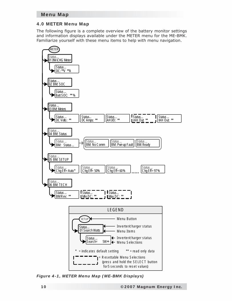
Figure 4-1, METER Menu Map (ME-BMK Displays)
M ETER
Status ...04 BM: Status
Status ...BM: Status ...
Status...BM: No Comm
Status ...BM: Pwr-up Fault
Status ...BM: Ready
Status ...05 BM: SETUP
Status ...Chg Eff= Auto*
Status ...Chg Eff= 50%
Status ...Chg Eff= 60%
Status ...Chg Eff= 97%.....
Status ...06 BM: TECH
Status ...BM Rev: **
* * = read on ly da ta
SETU P
Status...01 Search Watts
Status ...Search= 5W
M enu B ut ton
Inv erte r/c harger s ta tus
Inv erte r/c harger s ta tus
M enu I tem s
M enu S e lec t ions
* = ind ic a tes de fau lt s e t t ing
LEGEN D
Status ...03 BM: Meters
Status ...02 BM: SOC
Status ...Batt SOC: ** %
Status…01 INV/CHG Meter
Status...DC: **V **A
Status ...DC Volts: **
Status...DC Amps: **
Status...AH I/O: **
Status...rAH Out: **
Status ...tAH Out: **
= R es et tab le M enu S e lec t ions (p res s and ho ld the S E LE C T but ton f o r 5 s ec onds to res e t v a lues)
Status...Max DC: **
Status...Min DC: **
4.0 METER Menu Map
The following fi gure is a complete overview of the battery monitor settings and information displays available under the METER menu for the ME-BMK. Familiarize yourself with these menu items to help with menu navigation.
©2007 Magnum Energy Inc. 11
Operation
5.0 Operation
This section explains how the ME-BMK battery monitor works and how to operate the ME-RC remote control to obtain information on the battery bank. The LCD displays on the ME-RC related to the battery monitor and the status of the Sense Module’s LED indicator is also explained in this section.
Info: For information on navigating the remote control, see the ME-RC Owner’s Manual (PN: 64-0003).
Info: See fi gure 4-1, METER Menu Map (ME-BMK Displays) for a complete map of the menu items and adjustable settings available for the ME-BMK battery monitor using the ME-RC remote control.
5.0.1 How does the Battery Monitor (ME-BMK) Operate? The ME-BMK battery monitor uses a precision resistor known as a shunt to measure current fl ow into and out of the battery. The shunt provides a small voltage to the sense module that is proportional to the current fl ow. When current starts fl owing into or out of the battery, the sense module measures the current fl ow and determines the amount of current removed from and returned to the battery. The amount of current or “amp-hours” removed or returned is displayed on the ME-RC remote control as the AH I/O (Amp-Hours In/Out). The AH I/O number is compensated by a charging effi ciency value that accounts for energy loses while charging and is one of the factors used to determine the battery’s State Of Charge (SOC).
The battery’s State of Charge - which is the best indicator of the condition of the batteries - is indicated on the SOC display. This display will show that the batteries are fully charged (i.e. SOC = 100%) only after the following three conditions have been met:
The charging voltage - over a period of time - has stabilized;
the charging current has decreased to a low percentage of the amp-hour capacity - normally less than 2%; and
the amp-hours that were removed from the battery are within 1% of fully being returned;
After the batteries have reached 100% SOC and have discharged ≥ 0.5% of the battery capacity setting, the charge effi ciency value will be recalculated and the AH I/O readout will reset to the recalculated value.
Info: To help maintain the accuracy of the SOC display and to keep the batteries in good condition, it is necessary to fully charge them occasionally (approximately once a week).
Info: When charging from a generator (non-inverter topology) and deeply concerned about the cost of fuel; a balance should be con-sidered between the use of fuel against charging batteries to 100% SOC to maintain the full service life of a battery. Batteries discharged to 50% SOC and normally recharged to 85-90% SOC would be an effi cient compromise between fuel cost and battery life. Trying to restore the last 10-15% for a full battery charge requires a long time - typically several hours.
1.
2.
3.
12 ©2007 Magnum Energy Inc.
Operation
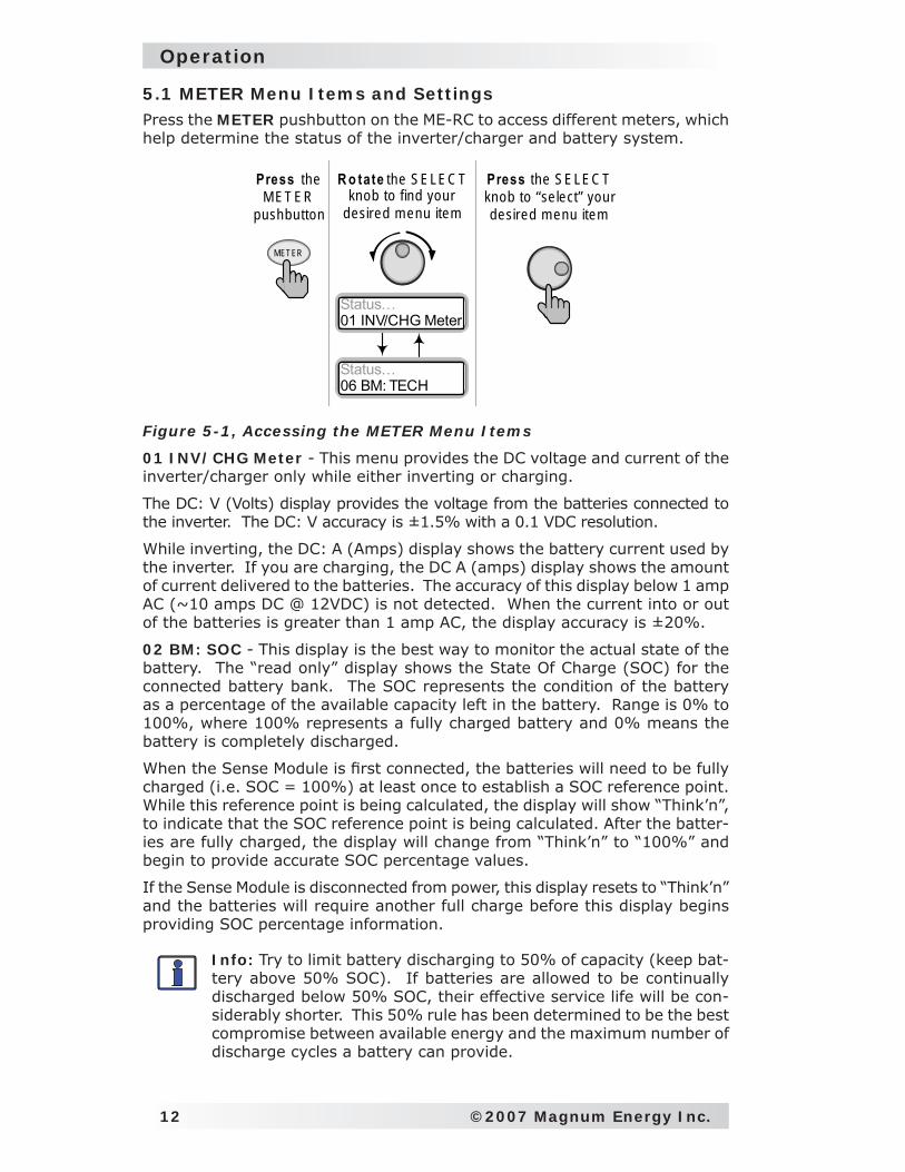
5.1 METER Menu Items and SettingsPress the METER pushbutton on the ME-RC to access different meters, which help determine the status of the inverter/charger and battery system.
Figure 5-1, Accessing the METER Menu Items
01 INV/CHG Meter - This menu provides the DC voltage and current of the inverter/charger only while either inverting or charging.
The DC: V (Volts) display provides the voltage from the batteries connected to the inverter. The DC: V accuracy is ±1.5% with a 0.1 VDC resolution.
While inverting, the DC: A (Amps) display shows the battery current used by the inverter. If you are charging, the DC A (amps) display shows the amount of current delivered to the batteries. The accuracy of this display below 1 amp AC (~10 amps DC @ 12VDC) is not detected. When the current into or out of the batteries is greater than 1 amp AC, the display accuracy is ±20%.
02 BM: SOC - This display is the best way to monitor the actual state of the battery. The “read only” display shows the State Of Charge (SOC) for the connected battery bank. The SOC represents the condition of the battery as a percentage of the available capacity left in the battery. Range is 0% to 100%, where 100% represents a fully charged battery and 0% means the battery is completely discharged.
When the Sense Module is fi rst connected, the batteries will need to be fully charged (i.e. SOC = 100%) at least once to establish a SOC reference point. While this reference point is being calculated, the display will show “Think’n”, to indicate that the SOC reference point is being calculated. After the batter-ies are fully charged, the display will change from “Think’n” to “100%” and begin to provide accurate SOC percentage values.
If the Sense Module is disconnected from power, this display resets to “Think’n” and the batteries will require another full charge before this display begins providing SOC percentage information.
Info: Try to limit battery discharging to 50% of capacity (keep bat-tery above 50% SOC). If batteries are allowed to be continually discharged below 50% SOC, their effective service life will be con-siderably shorter. This 50% rule has been determined to be the best compromise between available energy and the maximum number of discharge cycles a battery can provide.
Press the SELEC T knob to “se lect” your desired m enu item
METER
Press the M ET ER
pushbutton
Status…01 INV/CHG Meter
Status…06 BM: TECH
R o tate the SELEC T knob to find your
desired m enu item
©2007 Magnum Energy Inc. 13
Operation
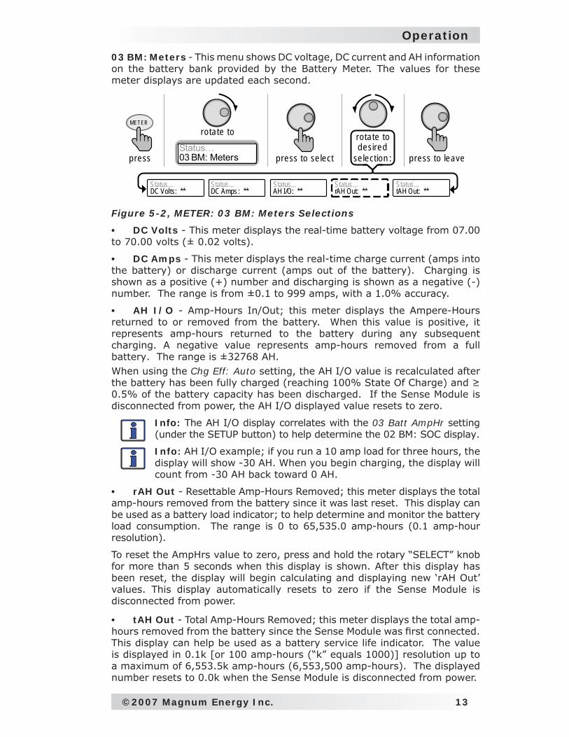
03 BM: Meters - This menu shows DC voltage, DC current and AH information on the battery bank provided by the Battery Meter. The values for these meter displays are updated each second.
Figure 5-2, METER: 03 BM: Meters Selections
DC Volts - This meter displays the real-time battery voltage from 07.00 to 70.00 volts (± 0.02 volts).
DC Amps - This meter displays the real-time charge current (amps into the battery) or discharge current (amps out of the battery). Charging is shown as a positive (+) number and discharging is shown as a negative (-) number. The range is from ±0.1 to 999 amps, with a 1.0% accuracy.
AH I/O - Amp-Hours In/Out; this meter displays the Ampere-Hours returned to or removed from the battery. When this value is positive, it represents amp-hours returned to the battery during any subsequent charging. A negative value represents amp-hours removed from a full battery. The range is ±32768 AH. When using the Chg Eff: Auto setting, the AH I/O value is recalculated after the battery has been fully charged (reaching 100% State Of Charge) and ≥ 0.5% of the battery capacity has been discharged. If the Sense Module is disconnected from power, the AH I/O displayed value resets to zero.
Info: The AH I/O display correlates with the 03 Batt AmpHr setting (under the SETUP button) to help determine the 02 BM: SOC display.
Info: AH I/O example; if you run a 10 amp load for three hours, the display will show -30 AH. When you begin charging, the display will count from -30 AH back toward 0 AH.
rAH Out - Resettable Amp-Hours Removed; this meter displays the total amp-hours removed from the battery since it was last reset. This display can be used as a battery load indicator; to help determine and monitor the battery load consumption. The range is 0 to 65,535.0 amp-hours (0.1 amp-hour resolution).
To reset the AmpHrs value to zero, press and hold the rotary “SELECT” knob for more than 5 seconds when this display is shown. After this display has been reset, the display will begin calculating and displaying new ‘rAH Out’ values. This display automatically resets to zero if the Sense Module is disconnected from power.
tAH Out - Total Amp-Hours Removed; this meter displays the total amp-hours removed from the battery since the Sense Module was fi rst connected. This display can help be used as a battery service life indicator. The value is displayed in 0.1k [or 100 amp-hours (“k” equals 1000)] resolution up to a maximum of 6,553.5k amp-hours (6,553,500 amp-hours). The displayed number resets to 0.0k when the Sense Module is disconnected from power.
•
•
•
•
•
press to leave
METER
pressStatus…03 BM: Meters
ro tate to
press to se lect
rotate to desired
se lection :
Status...DC Volts: **
Status...AH I/O: **
Status...DC Amps : **
Status...rAH Out: **
Status...tAH Out: **
14 ©2007 Magnum Energy Inc.
Operation
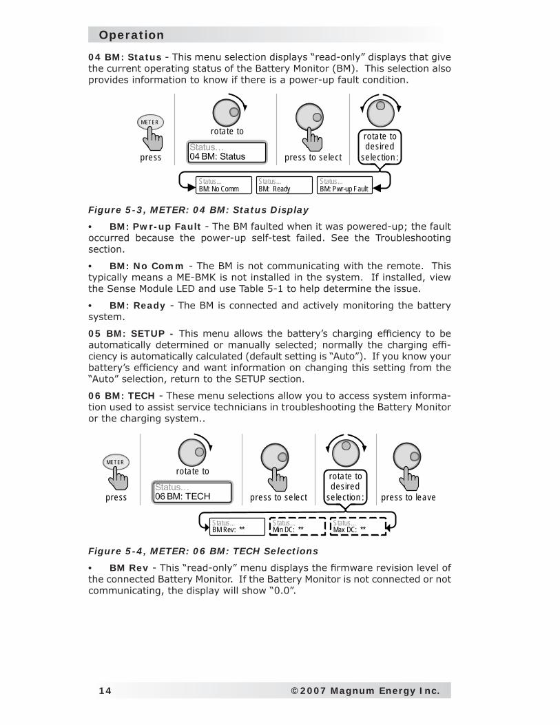
04 BM: Status - This menu selection displays “read-only” displays that give the current operating status of the Battery Monitor (BM). This selection also provides information to know if there is a power-up fault condition.
Figure 5-3, METER: 04 BM: Status Display
BM: Pwr-up Fault - The BM faulted when it was powered-up; the fault occurred because the power-up self-test failed. See the Troubleshooting section.
BM: No Comm - The BM is not communicating with the remote. This typically means a ME-BMK is not installed in the system. If installed, view the Sense Module LED and use Table 5-1 to help determine the issue.
BM: Ready - The BM is connected and actively monitoring the battery system.
05 BM: SETUP - This menu allows the battery’s charging effi ciency to be automatically determined or manually selected; normally the charging effi -ciency is automatically calculated (default setting is “Auto”). If you know your battery’s effi ciency and want information on changing this setting from the “Auto” selection, return to the SETUP section.
06 BM: TECH - These menu selections allow you to access system informa-tion used to assist service technicians in troubleshooting the Battery Monitor or the charging system..
Figure 5-4, METER: 06 BM: TECH Selections
BM Rev - This “read-only” menu displays the fi rmware revision level of the connected Battery Monitor. If the Battery Monitor is not connected or not communicating, the display will show “0.0”.
•
•
•
•
Status...BM: No Comm
Status...BM: Pwr-up Fault
Status...BM: Ready
METER
pressStatus…04 BM: Status
ro tate to
press to se lect
rotate to desired
se lection :
Status...BM Rev: **
Status...Min DC: **
Status...Max DC: **
press to leave
METER
pressStatus…06 BM: TECH
ro tate to
press to se lect
rotate to desired
se lection :
©2007 Magnum Energy Inc. 15
Operation
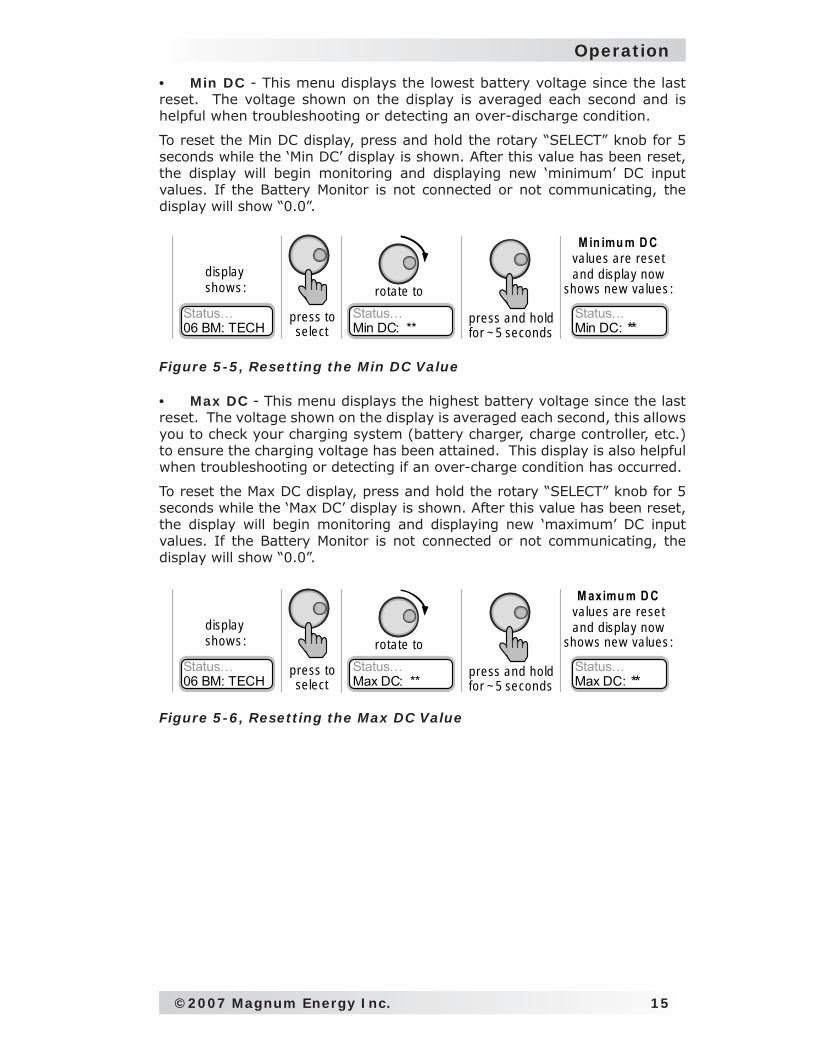
Min DC - This menu displays the lowest battery voltage since the last reset. The voltage shown on the display is averaged each second and is helpful when troubleshooting or detecting an over-discharge condition.
To reset the Min DC display, press and hold the rotary “SELECT” knob for 5 seconds while the ‘Min DC’ display is shown. After this value has been reset, the display will begin monitoring and displaying new ‘minimum’ DC input values. If the Battery Monitor is not connected or not communicating, the display will show “0.0”.
•
Status…06 BM: TECH
disp lay show s :
Status…Max DC: **
ro tate toStatus…Max DC: **
M aximu m D C values are reset and d isp lay now
show s new values :
press toselect
press and hold for ~ 5 seconds
Figure 5-6, Resetting the Max DC Value
Status…06 BM: TECH
disp lay show s :
Status…Min DC: **
ro tate toStatus…Min DC: **
M in imu m D C values are reset and d isp lay now
show s new values :
press toselect
press and hold for ~ 5 seconds
Figure 5-5, Resetting the Min DC Value
Max DC - This menu displays the highest battery voltage since the last reset. The voltage shown on the display is averaged each second, this allows you to check your charging system (battery charger, charge controller, etc.) to ensure the charging voltage has been attained. This display is also helpful when troubleshooting or detecting if an over-charge condition has occurred.
To reset the Max DC display, press and hold the rotary “SELECT” knob for 5 seconds while the ‘Max DC’ display is shown. After this value has been reset, the display will begin monitoring and displaying new ‘maximum’ DC input values. If the Battery Monitor is not connected or not communicating, the display will show “0.0”.
•
16 ©2007 Magnum Energy Inc.
Operation
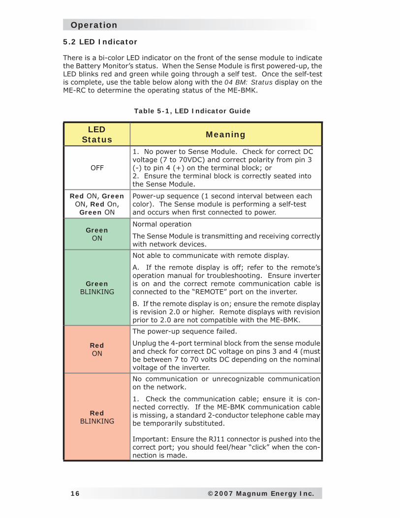
5.2 LED Indicator
There is a bi-color LED indicator on the front of the sense module to indicate the Battery Monitor’s status. When the Sense Module is fi rst powered-up, the LED blinks red and green while going through a self test. Once the self-test is complete, use the table below along with the 04 BM: Status display on the ME-RC to determine the operating status of the ME-BMK.
Table 5-1, LED Indicator Guide
LEDStatus Meaning
OFF
1. No power to Sense Module. Check for correct DC voltage (7 to 70VDC) and correct polarity from pin 3 (-) to pin 4 (+) on the terminal block; or2. Ensure the terminal block is correctly seated into the Sense Module.
Red ON, Green ON, Red On, Green ON
Power-up sequence (1 second interval between each color). The Sense module is performing a self-test and occurs when fi rst connected to power.
GreenON
Normal operation
The Sense Module is transmitting and receiving correctly with network devices.
GreenBLINKING
Not able to communicate with remote display.
A. If the remote display is off; refer to the remote’s operation manual for troubleshooting. Ensure inverter is on and the correct remote communication cable is connected to the “REMOTE” port on the inverter.
B. If the remote display is on; ensure the remote display is revision 2.0 or higher. Remote displays with revision prior to 2.0 are not compatible with the ME-BMK.
RedON
The power-up sequence failed.
Unplug the 4-port terminal block from the sense module and check for correct DC voltage on pins 3 and 4 (must be between 7 to 70 volts DC depending on the nominal voltage of the inverter.
RedBLINKING
No communication or unrecognizable communication on the network.
1. Check the communication cable; ensure it is con-nected correctly. If the ME-BMK communication cable is missing, a standard 2-conductor telephone cable may be temporarily substituted.
Important: Ensure the RJ11 connector is pushed into the correct port; you should feel/hear “click” when the con-nection is made.
©2007 Magnum Energy Inc. 17
Troubleshooting
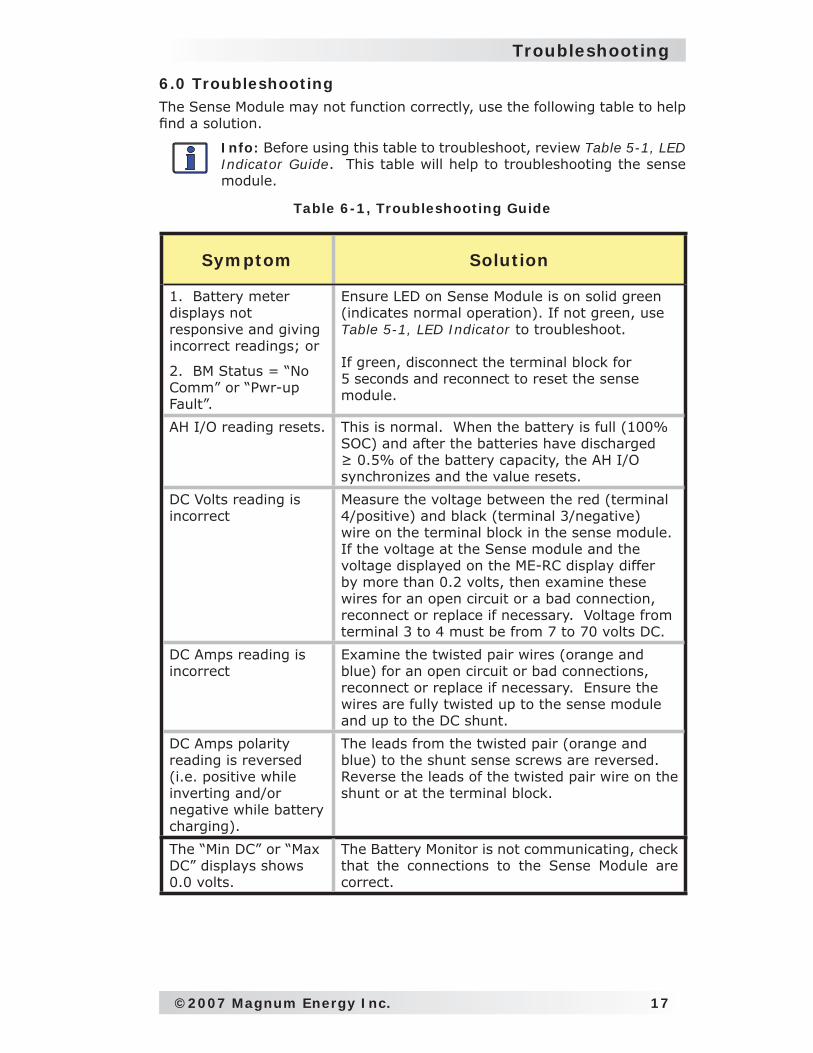
6.0 Troubleshooting The Sense Module may not function correctly, use the following table to help fi nd a solution.
Info: Before using this table to troubleshoot, review Table 5-1, LED Indicator Guide. This table will help to troubleshooting the sense module.
Table 6-1, Troubleshooting Guide
Symptom Solution
1. Battery meter displays not responsive and giving incorrect readings; or
2. BM Status = “No Comm” or “Pwr-up Fault”.
Ensure LED on Sense Module is on solid green (indicates normal operation). If not green, use Table 5-1, LED Indicator to troubleshoot.
If green, disconnect the terminal block for 5 seconds and reconnect to reset the sense module.
AH I/O reading resets. This is normal. When the battery is full (100% SOC) and after the batteries have discharged ≥ 0.5% of the battery capacity, the AH I/O synchronizes and the value resets.
DC Volts reading is incorrect
Measure the voltage between the red (terminal 4/positive) and black (terminal 3/negative) wire on the terminal block in the sense module. If the voltage at the Sense module and the voltage displayed on the ME-RC display differ by more than 0.2 volts, then examine these wires for an open circuit or a bad connection, reconnect or replace if necessary. Voltage from terminal 3 to 4 must be from 7 to 70 volts DC.
DC Amps reading is incorrect
Examine the twisted pair wires (orange and blue) for an open circuit or bad connections, reconnect or replace if necessary. Ensure the wires are fully twisted up to the sense module and up to the DC shunt.
DC Amps polarity reading is reversed (i.e. positive while inverting and/or negative while battery charging).
The leads from the twisted pair (orange and blue) to the shunt sense screws are reversed. Reverse the leads of the twisted pair wire on the shunt or at the terminal block.
The “Min DC” or “Max DC” displays shows 0.0 volts.
The Battery Monitor is not communicating, check that the connections to the Sense Module are correct.
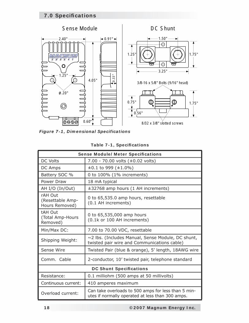
7.0 Specifi cations
18 ©2007 Magnum Energy Inc.
0.33
"
2 .40"
1.25"
0.91"
4.05"
1.75"
3.25"
1.50"
1.25"
1.75"
0.56"
0.75"
3/8-16 x 5/8" Bolts (9 /16" head)
8/32 x 3/8" slo tted screw s0.60"
ø .20"
S ense M odu le D C S hun t
Figure 7-1, Dimensional Specifications
Table 7-1, Specifi cations
Sense Module/Meter Specifi cations
DC Volts 7.00 - 70.00 volts (±0.02 volts)
DC Amps ±0.1 to 999 (±1.0%)
Battery SOC % 0 to 100% (1% increments)
Power Draw 18 mA typical
AH I/O (In/Out) ±32768 amp hours (1 AH increments)
rAH Out(Resettable Amp-Hours Removed)
0 to 65,535.0 amp hours, resettable(0.1 AH increments)
tAH Out(Total Amp-Hours Removed)
0 to 65,535,000 amp hours(0.1k or 100 AH increments)
Min/Max DC: 7.00 to 70.00 VDC, resettable
Shipping Weight: ~2 lbs. (Includes Manual, Sense Module, DC shunt, twisted pair wire and Communications cable)
Sense Wire Twisted Pair (blue & orange), 5’ length, 18AWG wire
Comm. Cable 2-conductor, 10’ twisted pair, telephone standard
DC Shunt Specifi cations
Resistance: 0.1 milliohm (500 amps at 50 millivolts)
Continuous current: 410 amperes maximum
Overload current: Can take overloads to 500 amps for less than 5 min-utes if normally operated at less than 300 amps.
©2007 Magnum Energy Inc. 19
Service and Warranty Info
8.0 Limited Warranty
Magnum Energy, Inc., warrants the ME-BMK battery monitor to be free from defects in material and workmanship that result in product failure during normal usage, according to the following terms and conditions:
1. The limited warranty for this product extends for 12 months from the product’s original date of purchase.
2. The limited warranty extends to the original purchaser of the product and is not assignable or transferable to any subsequent purchaser.
3. During the limited warranty period, Magnum Energy will repair, or replace at Magnum Energy’s option, any defective parts, or any parts that will not properly operate for their intended use with factory new or rebuilt replacement items if such repair or replacement is needed because of product malfunction or failure during normal usage. The limited warranty does not cover defects in appearance, cosmetic, decorative or structural parts or any non-operative parts. Magnum Energy’s limit of liability under the limited warranty shall be the actual cash value of the product at the time the original purchaser returns the product for repair, determined by the price paid by the original purchaser. Magnum Energy shall not be liable for any other losses or damages.
4. Upon request from Magnum Energy, the original purchaser must prove the product’s original date of purchase by a dated bill of sale, itemized receipt.
5. The original purchaser shall return the product prepaid to Magnum Energy in Everett, WA. After the completion of service under this limited warranty, Magnum Energy will return the product prepaid to the original purchaser via a Magnum-selected non-expedited surface freight within the contiguous United States and Canada; this excludes Alaska and Hawaii.
6. If Magnum repairs or replaces a product (with either a new or refurbished product), its warranty continues for the remaining portion of the original war-ranty period or 90 days from the date of the return shipment to the original purchaser, whichever is greater. All replaced products and parts removed from repaired products become the property of Magnum Energy.
7. This limited warranty is voided if:
• the product has been modifi ed without authorization,
• the serial number has been altered or removed,
• the product has been damaged through abuse, neglect, accident, high voltage or corrosion.
• the product was not installed and operated according to the owner’s manual.
BEFORE RETURNING ANY UNIT, CONTACT MAGNUM ENERGY FOR A RETURN MATERIAL AUTHORIZATION (RMA) NUMBER.

Magnum Energy, Inc.1111 80th Street SW - Suite 250
Everett, WA 98203Phone: 425.353.8833Fax: 425.353.8390
Web: www.magnumenergy.com
PN: 64-0013