Embed Size (px)
Citation preview
Syncline Geotechnical Engineering (Pty) Ltd Company Registration No. 2012/181469/07
Director: S. Pather Pr.Sci.Nat. BSc (Hons), MSAIEG, FGSSA, MAEG, NHBRC (Competent Engineer)
REPORT TO BMK ENGINEERING CONSULTANTSON THE RESULTS OF A GEOTECHNICAL INVESTIGATION
FOR PHASE 3 OF THE GROUTVILLE PRIORITY 2SANITATION PROJECT, ILEMBE DISTRICT MUNICIPALITY
KWAZULU-NATAL
REPORT REFERENCE: SGE-177-2013.REP03
Author: S. Pather (Pr.Sci.Nat.)
Practice No.: 400020/08 (South African Council for Natural Scientific Professions)
Date: 20 February 2014
Syncline Geotechnical Engineering (Pty) Ltd
Physical Address:
Unit 417, Mazars House197 Peter Mokaba (North Ridge) RoadMorningsideDurban4001
Telephone No.: 031-207 1383
Fax No.: 031-207 1349
Mobile No.: 084-500 5095
Administration E-Mail: [email protected]
Director E-Mail: [email protected]
Website www.synclinegeo.co.za
Syncline Geotechnical Engineering (Pty) Ltd
REPORT TO BMK ENGINEERING CONSULTANTSON THE RESULTS OF A GEOTECHNICAL INVESTIGATION
FOR PHASE 3 OF THE GROUTVILLE PRIORITY 2SANITATION PROJECT, ILEMBE DISTRICT MUNICIPALITY
KWAZULU-NATAL
REPORT REFERENCE: SGE-177-2013.REP03
TABLE OF CONTENTS
1. TERMS OF REFERENCE .................................................................................................................. 1
2. SCOPE OF REPORT ......................................................................................................................... 1
3. INFORMATION SUPPLIED ............................................................................................................... 1
4. NATURE OF INVESTIGATION.......................................................................................................... 2
4.1 INSPECTION PITS .............................................................................................................................. 34.2 CBR DYNAMIC CONE PENETROMETER (DCP) TESTS ......................................................................... 34.3 LABORATORY TESTS ......................................................................................................................... 3
5. SITE DESCRIPTION .......................................................................................................................... 3
6. GENERAL GEOLOGY ....................................................................................................................... 4
7. GROUNDWATER CONDITIONS ....................................................................................................... 6
8. LABORATORY TESTS RESULTS.................................................................................................... 6
9. PIPELINE ROUTES............................................................................................................................ 8
9.1 GENERAL ......................................................................................................................................... 89.2 EXCAVATABILITY AND RIPPABILITY ..................................................................................................... 89.3 EXCAVATION PLANT .......................................................................................................................... 99.4 MATERIALS EVALUATION ................................................................................................................... 99.5 PRECAUTIONARY MEASURES............................................................................................................. 99.6 BACKFILL AND EROSION ASPECTS ................................................................................................... 109.7 TRENCH STABILITY.......................................................................................................................... 109.8 SUPERVISION DURING CONSTRUCTION............................................................................................. 11
10. CONCLUSION.................................................................................................................................. 11
Appendix A: Inspection Pit Log ProfilesAppendix B: CBR Dynamic Cone Penetrometer (DCP) TestsAppendix C: Results of Laboratory Tests
Figure 1: Site Plan (showing field test positions)Figure 2: Geology of Study Area
1
Syncline Geotechnical Engineering (Pty) Ltd
REPORT TO BMK ENGINEERING CONSULTANTSON THE RESULTS OF A GEOTECHNICAL INVESTIGATION
FOR PHASE 3 OF THE GROUTVILLE PRIORITY 2SANITATION PROJECT, ILEMBE DISTRICT MUNICIPALITY
KWAZULU-NATAL
1. TERMS OF REFERENCE
Syncline Geotechnical Engineering Pty (Ltd) (hereafter referred to as SGE) wasrequested by Mr P. Dhanee (of BMK Engineering Consultants) to submit aquotation for a geotechnical investigation for the “Groutville Priority 2 SanitationProject, Ilembe District Municipality, KwaZulu-Natal”.
SGE provided this proposal and cost estimate in an electronic messagereferenced “Proposal 204-2013” and dated 19 November 2013. SGE wassubsequently appointed to carry out the investigation as per an electronic mailreceived from Mr Dhanee, dated 05 December 2013.
2. SCOPE OF REPORT
This report sets out the results of a Geotechnical Investigation carried out for“Phase 3 of the Groutville, Priority 2 Sanitation Project, Ilembe District Municipality,KwaZulu-Natal”.
Surface mapping, subsurface testing, and sampling and testing of insitu materialshave been undertaken for the proposed sewer reticulation. A description of thegeology, subsoils and surface drainage features are documented and thevariations in the excavatability of the insitu materials assessed. The suitability ofthe insitu and commercial sources of materials has also been evaluated andclassified.
3. INFORMATION SUPPLIED
For the purposes of assisting with this investigation, BMK provided the followinginformation to SGE:
Directions to and Global Positioning System (GPS) co-ordinates of the studyarea; and
A copy of a drawing, in electronic format, titled “Groutville Priority 2 SanitationProject”, prepared by BMK Engineering Consultants (Drawing No: BMK-002).
SGE also made reference to the 1:250 000 Geological Map titled “2930 Durban”as published by the Geological Survey.
2
Syncline Geotechnical Engineering (Pty) Ltd
4. NATURE OF INVESTIGATION
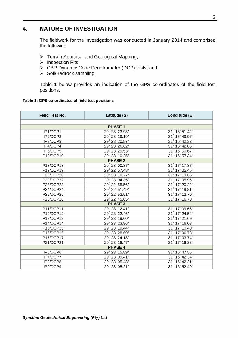
The fieldwork for the investigation was conducted in January 2014 and comprisedthe following:
Terrain Appraisal and Geological Mapping; Inspection Pits; CBR Dynamic Cone Penetrometer (DCP) tests; and Soil/Bedrock sampling.
Table 1 below provides an indication of the GPS co-ordinates of the field testpositions.
Table 1: GPS co-ordinates of field test positions
Field Test No. Latitude (S) Longitude (E)
PHASE 1IP1/DCP1 29
o23’ 23.93” 31
o16’ 51.42”
IP2/DCP2 29o
23’ 19.19” 31o
16’ 49.97”IP3/DCP3 29
o23’ 20.87” 31
o16’ 42.32”
IP4/DCP4 29o
23’ 26.62” 31o
16’ 42.06”IP5/DCP5 29
o23’ 29.53” 31
o16’ 50.67”
IP10/DCP10 29o
23’ 10.25” 31o
16’ 57.34”PHASE 2
IP18/DCP18 29o
23’ 00.37” 31o
17’ 17.87”IP19/DCP19 29
o22’ 57.43” 31
o17’ 05.45”
IP20/DCP20 29o
23’ 10.77” 31o
17’ 19.65”IP22/DCP22 29
o23’ 04.35” 31
o17’ 05.96”
IP23/DCP23 29o
22’ 55.56” 31o
17’ 20.22”IP24/DCP24 29
o22’ 51.49” 31
o17’ 19.81”
IP25/DCP25 29o
22’ 52.51” 31o
17’ 12.70”IP26/DCP26 29
o22’ 45.65” 31
o17’ 16.70”
PHASE 3IP11/DCP11 29
o23’ 12.41” 31
o17’ 09.66”
IP12/DCP12 29o
23’ 22.46” 31o
17’ 24.54”IP13/DCP13 29
o23’ 19.60” 31
o17’ 21.69”
IP14/DCP14 29o
23’ 23.86” 31o
17’ 16.08”IP15/DCP15 29
o23’ 19.44” 31
o17’ 10.40”
IP16/DCP16 29o
23’ 28.60” 31o
17’ 06.73”IP17/DCP17 29
o23’ 24.13” 31
o17’ 03.74”
IP21/DCP21 29o
23’ 16.47” 31o
17’ 16.33”PHASE 4
IP6/DCP6 29o
23’ 15.89” 31o
16’ 47.55”IP7/DCP7 29
o23’ 09.41” 31
o16’ 42.34”
IP8/DCP8 29o
23’ 05.43” 31o
16’ 42.21”IP9/DCP9 29
o23’ 05.21” 31
o16’ 52.49”
3
Syncline Geotechnical Engineering (Pty) Ltd
4.1 Inspection Pits
For Phase 3, eight inspection pits were excavated by hand at the approximatepositions indicated in Figure 1. The inspection pits were extended with a handauger to depths in the range 1.5 to 2.5 metres below existing ground level (EGL)and were profiled using the “Guidelines for Soil and Rock Logging in South Africa”,(2001)1. Copies of the detailed profiles are given in Appendix A.
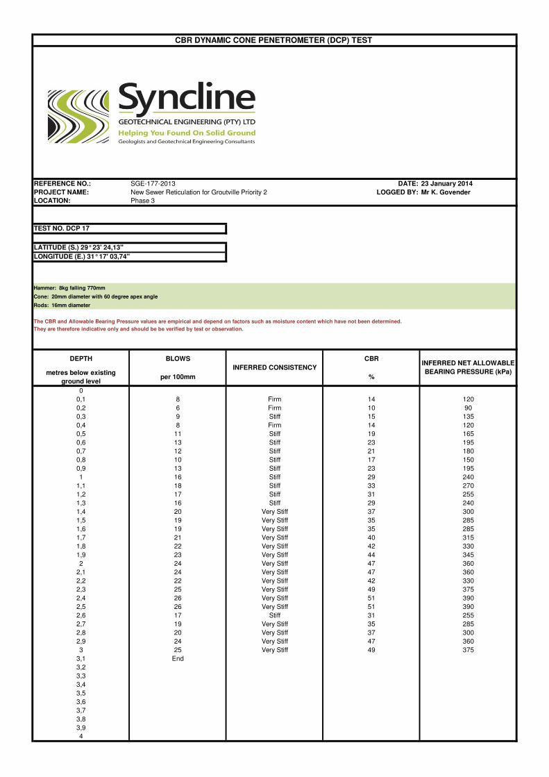
4.2 CBR Dynamic Cone Penetrometer (DCP) Tests
For Phase 3, eight CBR Dynamic Cone Penetrometer (DCP) tests, designatedwere carried out at the approximate positions given in Figure 1. The DCP testswere advanced to depths of equipment refusal or to a final depth of 3.0 metresbelow existing ground level. The results of the DCP tests comprising plots of blowcounts versus depth are given in Appendix B.
4.3 Laboratory Tests
Disturbed samples were retrieved from the inspection pits and sent to a soilmaterials laboratory for the following laboratory tests:
Particle size distribution/grading; and Atterberg Limits;
The results of the laboratory tests are given in Appendix C.
5. SITE DESCRIPTION
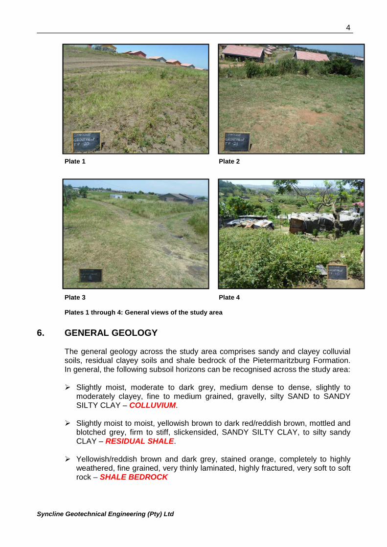
The study area is located in the township of Groutville, approximately 5km south ofKwaDukuza and represents the newly established Njekane and Etsheni Low CostHousing Project (which lies between the Umvoti River in the north and theGroutville main road in the south).
The site is characterised by gentle to moderate sloping hills with locally steepsections and valley lines/streams which drain to the Umvoti River in the north.
Plates 1 through 4 below provide an indication of the study area.
1 AEG, SAICE and SAIEG. "Guidelines for Soil and Rock Logging in South Africa". Editors, A. B. A. Brink and R. M. H.Bruin; Proceedings, Geoterminology Workshop, Johannesburg 2001.
4
Syncline Geotechnical Engineering (Pty) Ltd
Plate 1 Plate 2
Plate 3 Plate 4
Plates 1 through 4: General views of the study area
6. GENERAL GEOLOGY
The general geology across the study area comprises sandy and clayey colluvialsoils, residual clayey soils and shale bedrock of the Pietermaritzburg Formation.In general, the following subsoil horizons can be recognised across the study area:
Slightly moist, moderate to dark grey, medium dense to dense, slightly tomoderately clayey, fine to medium grained, gravelly, silty SAND to SANDYSILTY CLAY – COLLUVIUM.
Slightly moist to moist, yellowish brown to dark red/reddish brown, mottled andblotched grey, firm to stiff, slickensided, SANDY SILTY CLAY, to silty sandyCLAY – RESIDUAL SHALE.
Yellowish/reddish brown and dark grey, stained orange, completely to highlyweathered, fine grained, very thinly laminated, highly fractured, very soft to softrock – SHALE BEDROCK
5
Syncline Geotechnical Engineering (Pty) Ltd
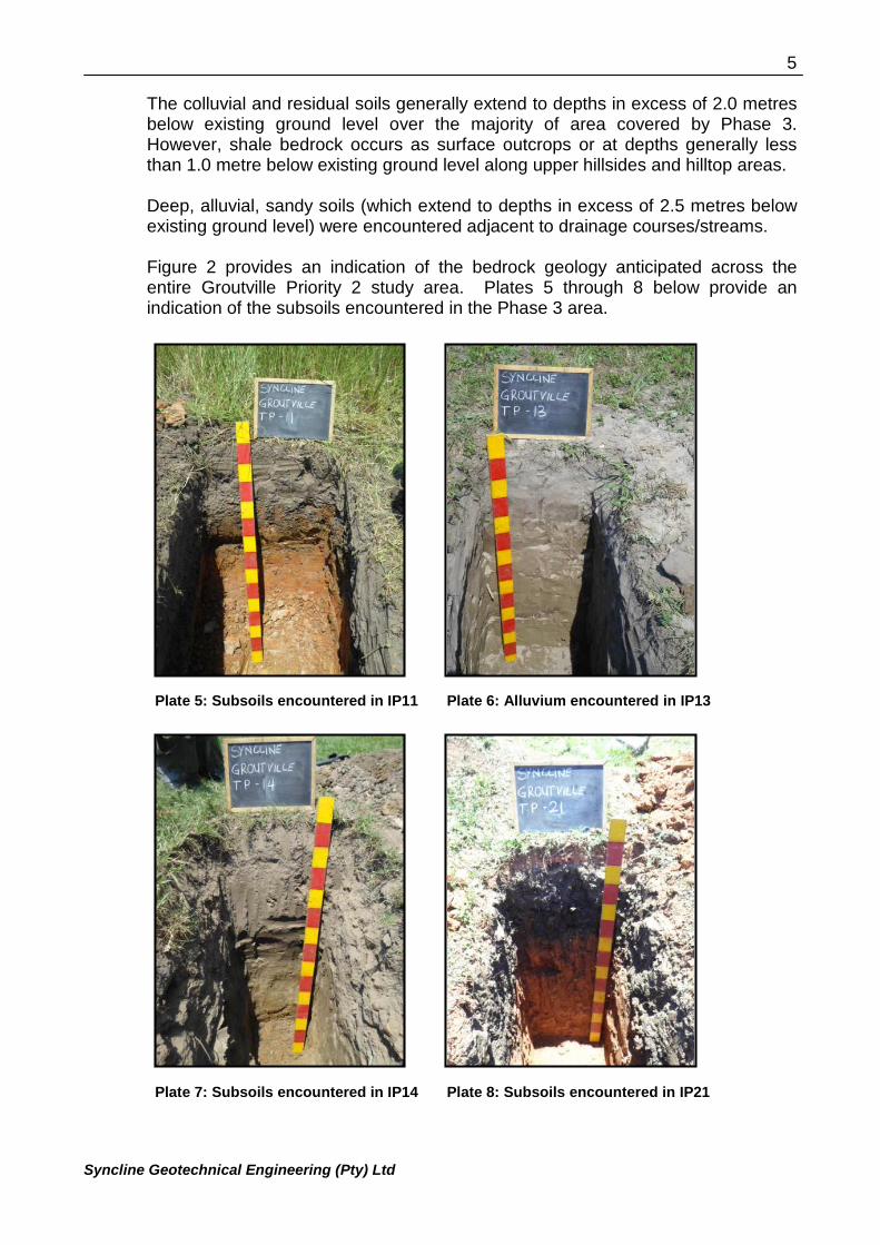
The colluvial and residual soils generally extend to depths in excess of 2.0 metresbelow existing ground level over the majority of area covered by Phase 3.However, shale bedrock occurs as surface outcrops or at depths generally lessthan 1.0 metre below existing ground level along upper hillsides and hilltop areas.
Deep, alluvial, sandy soils (which extend to depths in excess of 2.5 metres belowexisting ground level) were encountered adjacent to drainage courses/streams.
Figure 2 provides an indication of the bedrock geology anticipated across theentire Groutville Priority 2 study area. Plates 5 through 8 below provide anindication of the subsoils encountered in the Phase 3 area.
Plate 5: Subsoils encountered in IP11 Plate 6: Alluvium encountered in IP13
Plate 7: Subsoils encountered in IP14 Plate 8: Subsoils encountered in IP21
6
Syncline Geotechnical Engineering (Pty) Ltd
7. GROUNDWATER CONDITIONS
Moist to very moist subsoils were encountered close to existing drainage coursesand surface water was encountered along some of the stream crossings. Duecognisance of this shallow water table in the vicinity of stream/drainage crossingswill need to be taken into account during the construction phase and an allowancefor de-watering of pipeline trench excavations close to the drainage areas wouldneed to be considered.
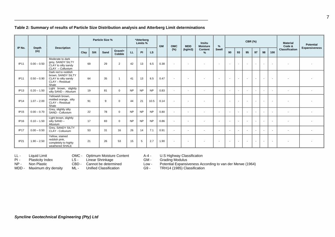
8. LABORATORY TESTS RESULTS
The laboratory tests results are given in Appendix C and are summarised in Table2 below.
7
Syncline Geotechnical Engineering (Pty) Ltd
Table 2: Summary of results of Particle Size Distribution analysis and Atterberg Limit determinations
LL - Liquid Limit OMC - Optimum Moisture Content A-4 - U.S Highway ClassificationPI - Plasticity Index LS - Linear Shrinkage GM - Grading ModulusNP - Non Plastic CBD - Cannot be determined Low - Potential Expansiveness According to van der Merwe (1964)MDD - Maximum dry density ML - Unified Classification G9 - TRH14 (1985) Classification
IP No. Depth(m)
Description
Particle Size % *AtterbergLimits %
GM OMC(%)
MDD(kg/m3)
InsituMoistureContent
%
%Swell
CBR (%)MaterialCode &
Classification
PotentialExpansiveness
Clay Silt SandGravel+Cobble
LL PI LS 90 93 95 97 98 100
IP11 0.00 – 0.50
Moderate to darkgrey, SANDY SILTYCLAY to silty sandyCLAY – Colluvium
69 29 2 42 13 6.5 0.38 - - - - - - - - - - - -
IP11 0.50 – 0.90
Dark red to reddishbrown, SANDY SILTYCLAY to silty sandyCLAY – ResidualShale
64 35 1 41 13 6.5 0.47 - - - - - - - - - - - -
IP13 0.20 – 1.50Light brown, slightlysilty SAND – Alluvium 19 81 0 NP NP NP 0.83 - - - - - - - - - - - -
IP14 1.07 – 2.00
Yellowish brown,mottled orange, siltyCLAY – ResidualShale
91 9 0 44 21 10.5 0.14 - - - - - - - - - - - -
IP15 0.00 – 0.70Grey, slightly siltySAND - Colluvium 22 78 0 NP NP NP 0.80 - - - - - - - - - - - -
IP16 0.10 – 1.50Light brown, slightlysilty SAND –Alluvium
17 83 0 NP NP NP 0.86 - - - - - - - - - - - -
IP17 0.00 – 0.50Grey, SANDY SILTYCLAY - Colluvium 53 31 16 26 14 7.1 0.91 - - - - - - - - - - - -
IP21 1.90 – 2.50
Yellow, stainedreddish pink,completely to highlyweathered SHALE
21 26 53 15 5 2.7 1.90 - - - - - - - - - - - -
8
Syncline Geotechnical Engineering (Pty) Ltd
9. PIPELINE ROUTES
9.1 General
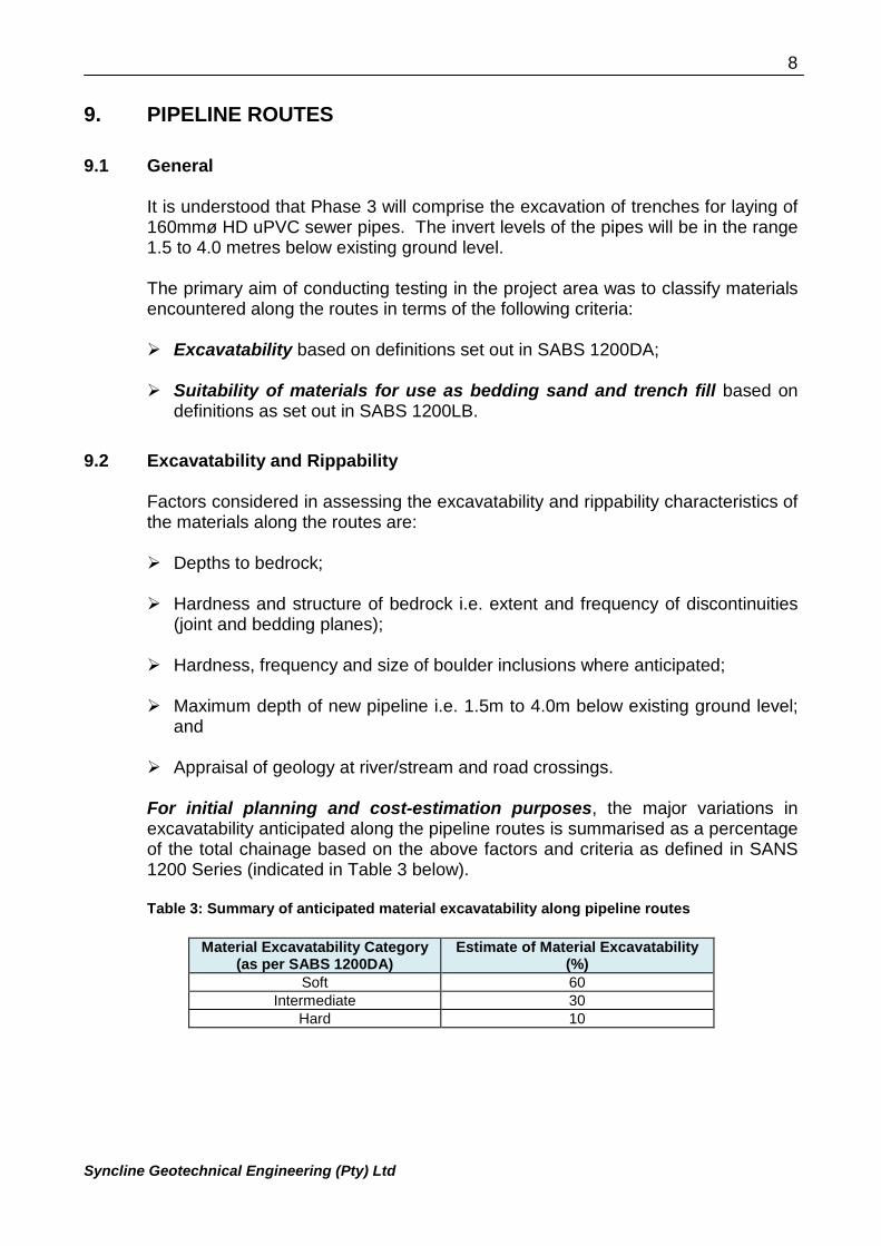
It is understood that Phase 3 will comprise the excavation of trenches for laying of160mmø HD uPVC sewer pipes. The invert levels of the pipes will be in the range1.5 to 4.0 metres below existing ground level.
The primary aim of conducting testing in the project area was to classify materialsencountered along the routes in terms of the following criteria:
Excavatability based on definitions set out in SABS 1200DA;
Suitability of materials for use as bedding sand and trench fill based ondefinitions as set out in SABS 1200LB.
9.2 Excavatability and Rippability
Factors considered in assessing the excavatability and rippability characteristics ofthe materials along the routes are:
Depths to bedrock;
Hardness and structure of bedrock i.e. extent and frequency of discontinuities(joint and bedding planes);
Hardness, frequency and size of boulder inclusions where anticipated;
Maximum depth of new pipeline i.e. 1.5m to 4.0m below existing ground level;and
Appraisal of geology at river/stream and road crossings.
For initial planning and cost-estimation purposes, the major variations inexcavatability anticipated along the pipeline routes is summarised as a percentageof the total chainage based on the above factors and criteria as defined in SANS1200 Series (indicated in Table 3 below).
Table 3: Summary of anticipated material excavatability along pipeline routes
Material Excavatability Category(as per SABS 1200DA)
Estimate of Material Excavatability(%)
Soft 60Intermediate 30
Hard 10
9
Syncline Geotechnical Engineering (Pty) Ltd
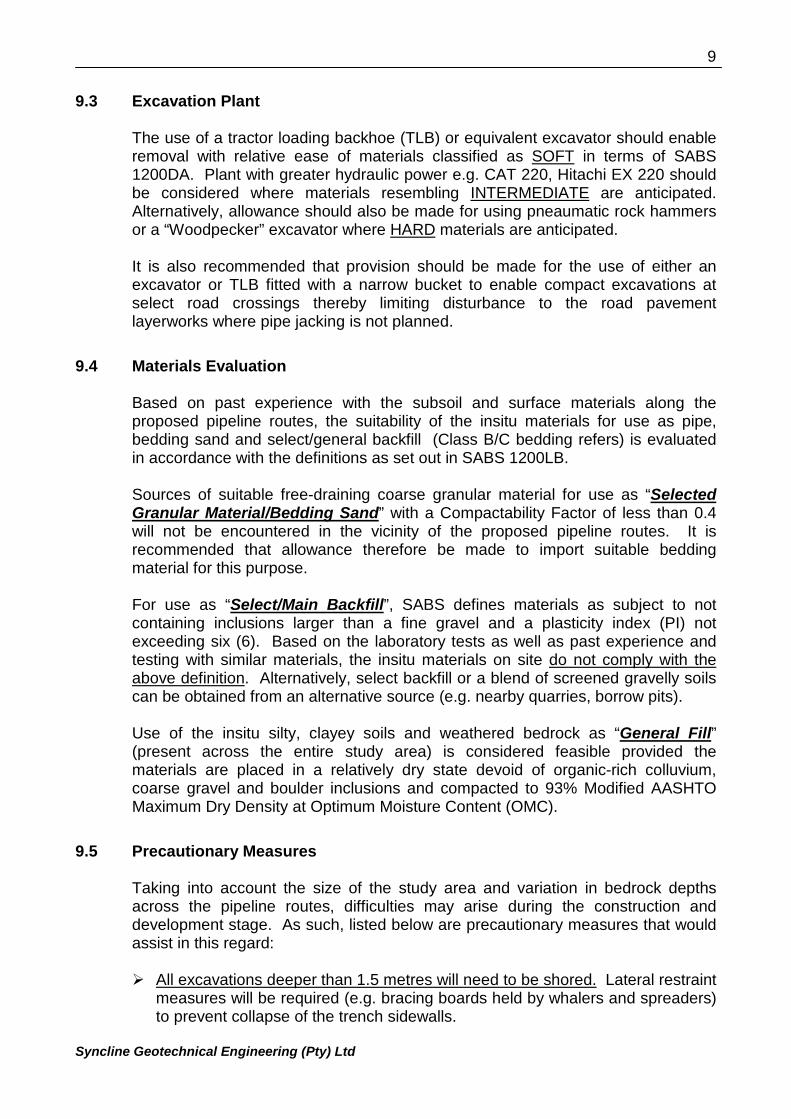
9.3 Excavation Plant
The use of a tractor loading backhoe (TLB) or equivalent excavator should enableremoval with relative ease of materials classified as SOFT in terms of SABS1200DA. Plant with greater hydraulic power e.g. CAT 220, Hitachi EX 220 shouldbe considered where materials resembling INTERMEDIATE are anticipated.Alternatively, allowance should also be made for using pneaumatic rock hammersor a “Woodpecker” excavator where HARD materials are anticipated.
It is also recommended that provision should be made for the use of either anexcavator or TLB fitted with a narrow bucket to enable compact excavations atselect road crossings thereby limiting disturbance to the road pavementlayerworks where pipe jacking is not planned.
9.4 Materials Evaluation
Based on past experience with the subsoil and surface materials along theproposed pipeline routes, the suitability of the insitu materials for use as pipe,bedding sand and select/general backfill (Class B/C bedding refers) is evaluatedin accordance with the definitions as set out in SABS 1200LB.
Sources of suitable free-draining coarse granular material for use as “SelectedGranular Material/Bedding Sand” with a Compactability Factor of less than 0.4will not be encountered in the vicinity of the proposed pipeline routes. It isrecommended that allowance therefore be made to import suitable beddingmaterial for this purpose.
For use as “Select/Main Backfill”, SABS defines materials as subject to notcontaining inclusions larger than a fine gravel and a plasticity index (PI) notexceeding six (6). Based on the laboratory tests as well as past experience andtesting with similar materials, the insitu materials on site do not comply with theabove definition. Alternatively, select backfill or a blend of screened gravelly soilscan be obtained from an alternative source (e.g. nearby quarries, borrow pits).
Use of the insitu silty, clayey soils and weathered bedrock as “General Fill”(present across the entire study area) is considered feasible provided thematerials are placed in a relatively dry state devoid of organic-rich colluvium,coarse gravel and boulder inclusions and compacted to 93% Modified AASHTOMaximum Dry Density at Optimum Moisture Content (OMC).
9.5 Precautionary Measures
Taking into account the size of the study area and variation in bedrock depthsacross the pipeline routes, difficulties may arise during the construction anddevelopment stage. As such, listed below are precautionary measures that wouldassist in this regard:
All excavations deeper than 1.5 metres will need to be shored. Lateral restraintmeasures will be required (e.g. bracing boards held by whalers and spreaders)to prevent collapse of the trench sidewalls.
10
Syncline Geotechnical Engineering (Pty) Ltd
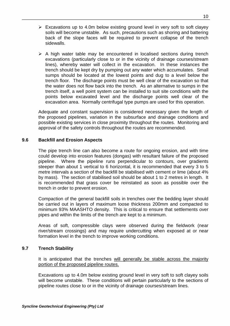
Excavations up to 4.0m below existing ground level in very soft to soft clayeysoils will become unstable. As such, precautions such as shoring and batteringback of the slope faces will be required to prevent collapse of the trenchsidewalls.
A high water table may be encountered in localised sections during trenchexcavations (particularly close to or in the vicinity of drainage courses/streamlines), whereby water will collect in the excavation. In these instances thetrench should be kept dry by pumping out any water which accumulates. Smallsumps should be located at the lowest points and dug to a level below thetrench floor. The discharge points must be well clear of the excavation so thatthe water does not flow back into the trench. As an alternative to sumps in thetrench itself, a well point system can be installed to suit site conditions with thepoints below excavated level and the discharge points well clear of theexcavation area. Normally centrifugal type pumps are used for this operation.
Adequate and constant supervision is considered necessary given the length ofthe proposed pipelines, variation in the subsurface and drainage conditions andpossible existing services in close proximity throughout the routes. Monitoring andapproval of the safety controls throughout the routes are recommended.
9.6 Backfill and Erosion Aspects
The pipe trench line can also become a route for ongoing erosion, and with timecould develop into erosion features (dongas) with resultant failure of the proposedpipeline. Where the pipeline runs perpendicular to contours, over gradientssteeper than about 1 vertical to 6 horizontal, it is recommended that every 3 to 5metre intervals a section of the backfill be stabilised with cement or lime (about 4%by mass). The section of stabilised soil should be about 1 to 2 metres in length. Itis recommended that grass cover be reinstated as soon as possible over thetrench in order to prevent erosion.
Compaction of the general backfill soils in trenches over the bedding layer shouldbe carried out in layers of maximum loose thickness 200mm and compacted tominimum 93% MAASHTO density. This is critical to ensure that settlements overpipes and within the limits of the trench are kept to a minimum.
Areas of soft, compressible clays were observed during the fieldwork (nearriver/stream crossings) and may require undercutting when exposed at or nearformation level in the trench to improve working conditions.
9.7 Trench Stability
It is anticipated that the trenches will generally be stable across the majorityportion of the proposed pipeline routes.
Excavations up to 4.0m below existing ground level in very soft to soft clayey soilswill become unstable. These conditions will pertain particularly to the sections ofpipeline routes close to or in the vicinity of drainage courses/stream lines.
11
Syncline Geotechnical Engineering (Pty) Ltd
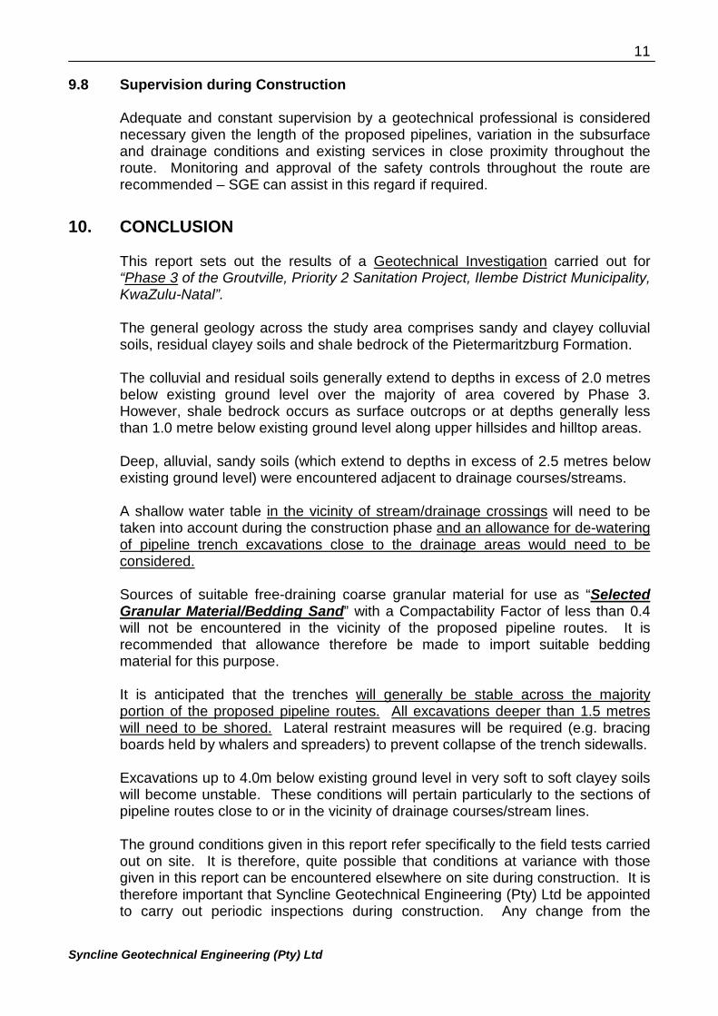
9.8 Supervision during Construction
Adequate and constant supervision by a geotechnical professional is considerednecessary given the length of the proposed pipelines, variation in the subsurfaceand drainage conditions and existing services in close proximity throughout theroute. Monitoring and approval of the safety controls throughout the route arerecommended – SGE can assist in this regard if required.
10. CONCLUSION
This report sets out the results of a Geotechnical Investigation carried out for“Phase 3 of the Groutville, Priority 2 Sanitation Project, Ilembe District Municipality,KwaZulu-Natal”.
The general geology across the study area comprises sandy and clayey colluvialsoils, residual clayey soils and shale bedrock of the Pietermaritzburg Formation.
The colluvial and residual soils generally extend to depths in excess of 2.0 metresbelow existing ground level over the majority of area covered by Phase 3.However, shale bedrock occurs as surface outcrops or at depths generally lessthan 1.0 metre below existing ground level along upper hillsides and hilltop areas.
Deep, alluvial, sandy soils (which extend to depths in excess of 2.5 metres belowexisting ground level) were encountered adjacent to drainage courses/streams.
A shallow water table in the vicinity of stream/drainage crossings will need to betaken into account during the construction phase and an allowance for de-wateringof pipeline trench excavations close to the drainage areas would need to beconsidered.
Sources of suitable free-draining coarse granular material for use as “SelectedGranular Material/Bedding Sand” with a Compactability Factor of less than 0.4will not be encountered in the vicinity of the proposed pipeline routes. It isrecommended that allowance therefore be made to import suitable beddingmaterial for this purpose.
It is anticipated that the trenches will generally be stable across the majorityportion of the proposed pipeline routes. All excavations deeper than 1.5 metreswill need to be shored. Lateral restraint measures will be required (e.g. bracingboards held by whalers and spreaders) to prevent collapse of the trench sidewalls.
Excavations up to 4.0m below existing ground level in very soft to soft clayey soilswill become unstable. These conditions will pertain particularly to the sections ofpipeline routes close to or in the vicinity of drainage courses/stream lines.
The ground conditions given in this report refer specifically to the field tests carriedout on site. It is therefore, quite possible that conditions at variance with thosegiven in this report can be encountered elsewhere on site during construction. It istherefore important that Syncline Geotechnical Engineering (Pty) Ltd be appointedto carry out periodic inspections during construction. Any change from the
12
Syncline Geotechnical Engineering (Pty) Ltd
anticipated ground conditions could then be taken into account to avoidunnecessary expense.
_______________________ 20 February 2014
Author: S Pather (Pr.Sci.Nat.) Date
APPENDIX AFebruary 20, 2014
INSPECTION PIT LOG PROFILES
0.00m--0.50m
0.50m--0.90m
BMK Engineering Consultants ccNew Sewer Reticulation for Groutville Priority 2Phase 3
HOLE No: IP 11Sheet 1 of 1
HOLE No: IP 11Sheet 1 of 1
HOLE No: IP 11Sheet 1 of 1
HOLE No: IP 11Sheet 1 of 1
JOB NUMBER: SGE-177-2013JOB NUMBER: SGE-177-2013
0.50
0.00
0.90
1.80
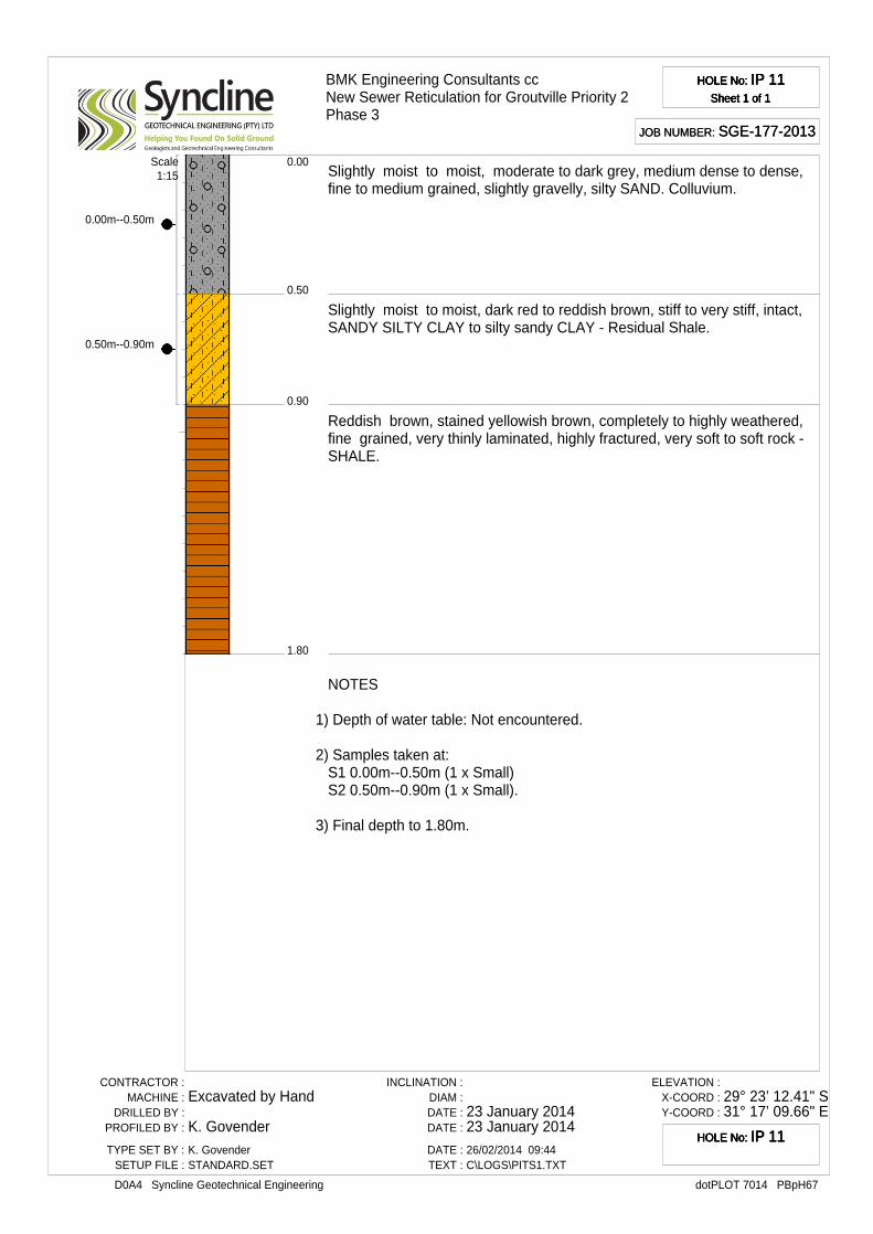
Slightly moist to moist, moderate to dark grey, medium dense to dense,fine to medium grained, slightly gravelly, silty SAND. Colluvium.
Slightly moist to moist, dark red to reddish brown, stiff to very stiff, intact,SANDY SILTY CLAY to silty sandy CLAY - Residual Shale.
Reddish brown, stained yellowish brown, completely to highly weathered,fine grained, very thinly laminated, highly fractured, very soft to soft rock -SHALE.
Scale1:15
NOTES
1) Depth of water table: Not encountered.
2) Samples taken at:S1 0.00m--0.50m (1 x Small)S2 0.50m--0.90m (1 x Small).
3) Final depth to 1.80m.
CONTRACTOR :MACHINE :
DRILLED BY :PROFILED BY :
TYPE SET BY :SETUP FILE :
Excavated by Hand
K. GovenderK. GovenderSTANDARD.SET
INCLINATION :DIAM :DATE :DATE :
DATE :TEXT :
23 January 201423 January 201426/02/2014 09:44C\LOGS\PITS1.TXT
ELEVATION :X-COORD :Y-COORD :
29° 23’ 12.41" S31° 17’ 09.66" E
dotPLOT 7014 PBpH67D0A4 Syncline Geotechnical Engineering
HOLE No: IP 11HOLE No: IP 11HOLE No: IP 11HOLE No: IP 11
BMK Engineering Consultants ccNew Sewer Reticulation for Groutville Priority 2Phase 3
HOLE No: IP 12Sheet 1 of 1
HOLE No: IP 12Sheet 1 of 1
HOLE No: IP 12Sheet 1 of 1
HOLE No: IP 12Sheet 1 of 1
JOB NUMBER: SGE-177-2013JOB NUMBER: SGE-177-2013
0.49
0.00
1.50
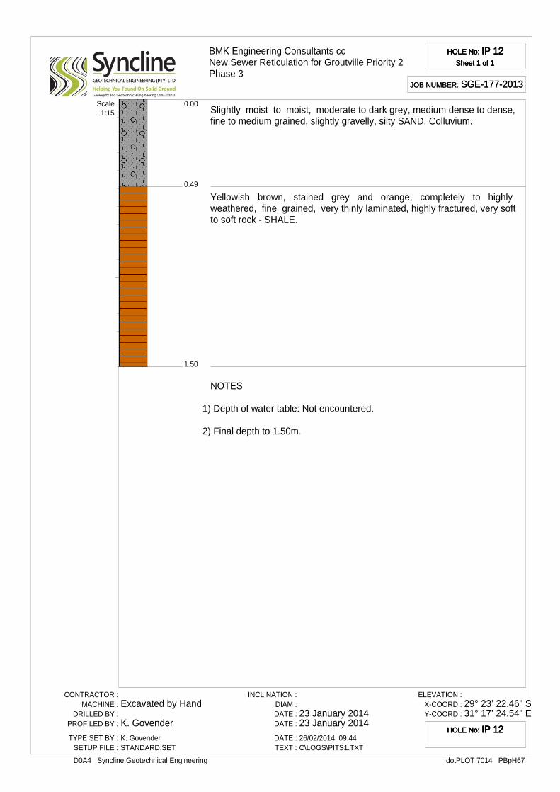
Slightly moist to moist, moderate to dark grey, medium dense to dense,fine to medium grained, slightly gravelly, silty SAND. Colluvium.
Yellowish brown, stained grey and orange, completely to highlyweathered, fine grained, very thinly laminated, highly fractured, very softto soft rock - SHALE.
Scale1:15
NOTES
1) Depth of water table: Not encountered.
2) Final depth to 1.50m.
CONTRACTOR :MACHINE :
DRILLED BY :PROFILED BY :
TYPE SET BY :SETUP FILE :
Excavated by Hand
K. GovenderK. GovenderSTANDARD.SET
INCLINATION :DIAM :DATE :DATE :
DATE :TEXT :
23 January 201423 January 201426/02/2014 09:44C\LOGS\PITS1.TXT
ELEVATION :X-COORD :Y-COORD :
29° 23’ 22.46" S31° 17’ 24.54" E
dotPLOT 7014 PBpH67D0A4 Syncline Geotechnical Engineering
HOLE No: IP 12HOLE No: IP 12HOLE No: IP 12HOLE No: IP 12
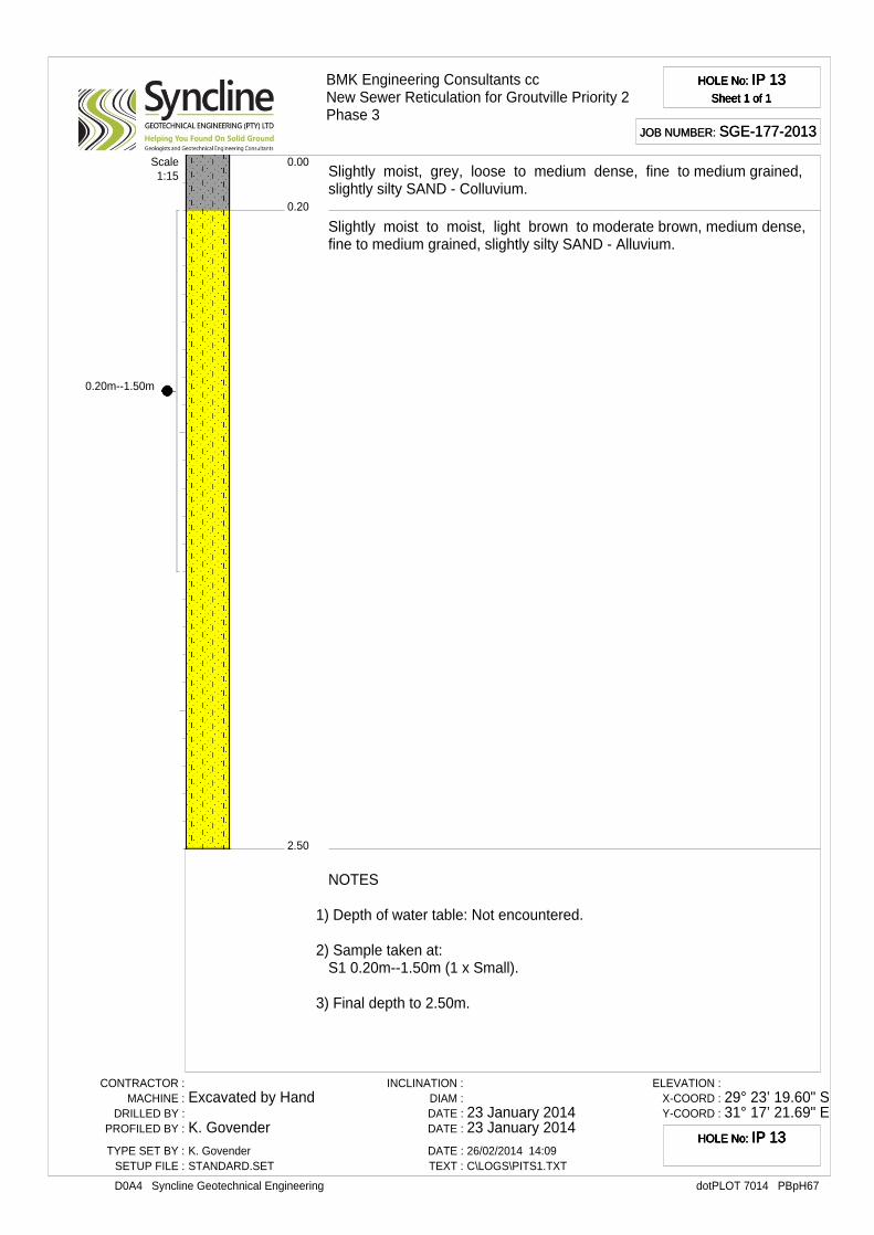
0.20m--1.50m
BMK Engineering Consultants ccNew Sewer Reticulation for Groutville Priority 2Phase 3
HOLE No: IP 13Sheet 1 of 1
HOLE No: IP 13Sheet 1 of 1
HOLE No: IP 13Sheet 1 of 1
HOLE No: IP 13Sheet 1 of 1
JOB NUMBER: SGE-177-2013JOB NUMBER: SGE-177-2013
0.20
0.00
2.50
Slightly moist, grey, loose to medium dense, fine to medium grained,slightly silty SAND - Colluvium.
Slightly moist to moist, light brown to moderate brown, medium dense,fine to medium grained, slightly silty SAND - Alluvium.
Scale1:15
NOTES
1) Depth of water table: Not encountered.
2) Sample taken at:S1 0.20m--1.50m (1 x Small).
3) Final depth to 2.50m.
CONTRACTOR :MACHINE :
DRILLED BY :PROFILED BY :
TYPE SET BY :SETUP FILE :
Excavated by Hand
K. GovenderK. GovenderSTANDARD.SET
INCLINATION :DIAM :DATE :DATE :
DATE :TEXT :
23 January 201423 January 201426/02/2014 14:09C\LOGS\PITS1.TXT
ELEVATION :X-COORD :Y-COORD :
29° 23’ 19.60" S31° 17’ 21.69" E
dotPLOT 7014 PBpH67D0A4 Syncline Geotechnical Engineering
HOLE No: IP 13HOLE No: IP 13HOLE No: IP 13HOLE No: IP 13
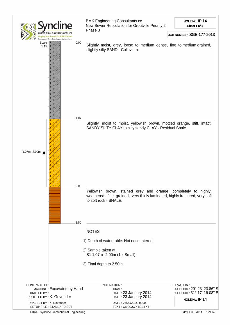
1.07m--2.00m
BMK Engineering Consultants ccNew Sewer Reticulation for Groutville Priority 2Phase 3
HOLE No: IP 14Sheet 1 of 1
HOLE No: IP 14Sheet 1 of 1
HOLE No: IP 14Sheet 1 of 1
HOLE No: IP 14Sheet 1 of 1
JOB NUMBER: SGE-177-2013JOB NUMBER: SGE-177-2013
1.07
0.00
2.00
2.50
Slightly moist, grey, loose to medium dense, fine to medium grained,slightly silty SAND - Colluvium.
Slightly moist to moist, yellowish brown, mottled orange, stiff, intact,SANDY SILTY CLAY to silty sandy CLAY - Residual Shale.
Yellowish brown, stained grey and orange, completely to highlyweathered, fine grained, very thinly laminated, highly fractured, very softto soft rock - SHALE.
Scale1:15
NOTES
1) Depth of water table: Not encountered.
2) Sample taken at:S1 1.07m--2.00m (1 x Small).
3) Final depth to 2.50m.
CONTRACTOR :MACHINE :
DRILLED BY :PROFILED BY :
TYPE SET BY :SETUP FILE :
Excavated by Hand
K. GovenderK. GovenderSTANDARD.SET
INCLINATION :DIAM :DATE :DATE :
DATE :TEXT :
23 January 201423 January 201426/02/2014 09:44C\LOGS\PITS1.TXT
ELEVATION :X-COORD :Y-COORD :
29° 23’ 23.86" S31° 17’ 16.08" E
dotPLOT 7014 PBpH67D0A4 Syncline Geotechnical Engineering
HOLE No: IP 14HOLE No: IP 14HOLE No: IP 14HOLE No: IP 14
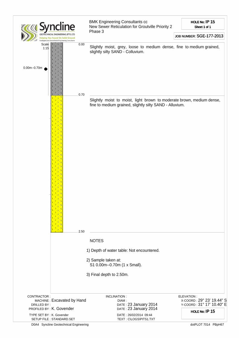
0.00m--0.70m
BMK Engineering Consultants ccNew Sewer Reticulation for Groutville Priority 2Phase 3
HOLE No: IP 15Sheet 1 of 1
HOLE No: IP 15Sheet 1 of 1
HOLE No: IP 15Sheet 1 of 1
HOLE No: IP 15Sheet 1 of 1
JOB NUMBER: SGE-177-2013JOB NUMBER: SGE-177-2013
0.70
0.00
2.50
Slightly moist, grey, loose to medium dense, fine to medium grained,slightly silty SAND - Colluvium.
Slightly moist to moist, light brown to moderate brown, medium dense,fine to medium grained, slightly silty SAND - Alluvium.
Scale1:15
NOTES
1) Depth of water table: Not encountered.
2) Sample taken at:S1 0.00m--0.70m (1 x Small).
3) Final depth to 2.50m.
CONTRACTOR :MACHINE :
DRILLED BY :PROFILED BY :
TYPE SET BY :SETUP FILE :
Excavated by Hand
K. GovenderK. GovenderSTANDARD.SET
INCLINATION :DIAM :DATE :DATE :
DATE :TEXT :
23 January 201423 January 201426/02/2014 09:44C\LOGS\PITS1.TXT
ELEVATION :X-COORD :Y-COORD :
29° 23’ 19.44" S31° 17’ 10.40" E
dotPLOT 7014 PBpH67D0A4 Syncline Geotechnical Engineering
HOLE No: IP 15HOLE No: IP 15HOLE No: IP 15HOLE No: IP 15
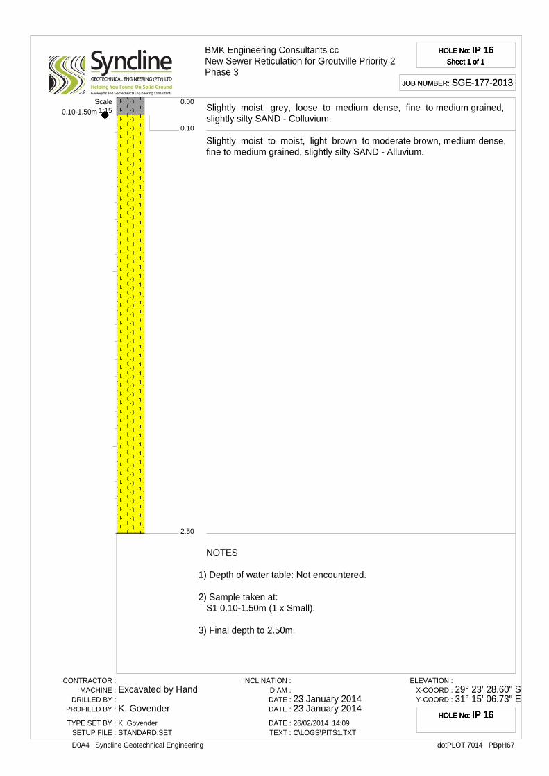
0.10-1.50m
BMK Engineering Consultants ccNew Sewer Reticulation for Groutville Priority 2Phase 3
HOLE No: IP 16Sheet 1 of 1
HOLE No: IP 16Sheet 1 of 1
HOLE No: IP 16Sheet 1 of 1
HOLE No: IP 16Sheet 1 of 1
JOB NUMBER: SGE-177-2013JOB NUMBER: SGE-177-2013
0.10
0.00
2.50
Slightly moist, grey, loose to medium dense, fine to medium grained,slightly silty SAND - Colluvium.
Slightly moist to moist, light brown to moderate brown, medium dense,fine to medium grained, slightly silty SAND - Alluvium.
Scale1:15
NOTES
1) Depth of water table: Not encountered.
2) Sample taken at:S1 0.10-1.50m (1 x Small).
3) Final depth to 2.50m.
CONTRACTOR :MACHINE :
DRILLED BY :PROFILED BY :
TYPE SET BY :SETUP FILE :
Excavated by Hand
K. GovenderK. GovenderSTANDARD.SET
INCLINATION :DIAM :DATE :DATE :
DATE :TEXT :
23 January 201423 January 201426/02/2014 14:09C\LOGS\PITS1.TXT
ELEVATION :X-COORD :Y-COORD :
29° 23’ 28.60" S31° 15’ 06.73" E
dotPLOT 7014 PBpH67D0A4 Syncline Geotechnical Engineering
HOLE No: IP 16HOLE No: IP 16HOLE No: IP 16HOLE No: IP 16
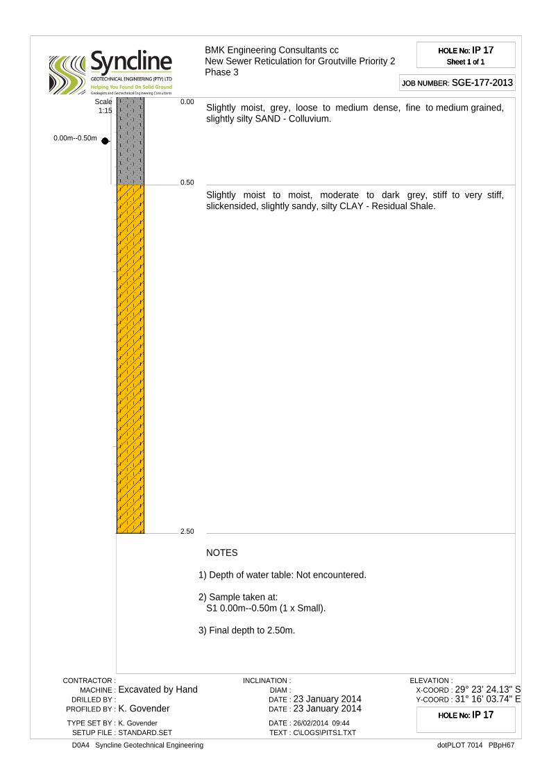
0.00m--0.50m
BMK Engineering Consultants ccNew Sewer Reticulation for Groutville Priority 2Phase 3
HOLE No: IP 17Sheet 1 of 1
HOLE No: IP 17Sheet 1 of 1
HOLE No: IP 17Sheet 1 of 1
HOLE No: IP 17Sheet 1 of 1
JOB NUMBER: SGE-177-2013JOB NUMBER: SGE-177-2013
0.50
0.00
2.50
Slightly moist, grey, loose to medium dense, fine to medium grained,slightly silty SAND - Colluvium.
Slightly moist to moist, moderate to dark grey, stiff to very stiff,slickensided, slightly sandy, silty CLAY - Residual Shale.
Scale1:15
NOTES
1) Depth of water table: Not encountered.
2) Sample taken at:S1 0.00m--0.50m (1 x Small).
3) Final depth to 2.50m.
CONTRACTOR :MACHINE :
DRILLED BY :PROFILED BY :
TYPE SET BY :SETUP FILE :
Excavated by Hand
K. GovenderK. GovenderSTANDARD.SET
INCLINATION :DIAM :DATE :DATE :
DATE :TEXT :
23 January 201423 January 201426/02/2014 09:44C\LOGS\PITS1.TXT
ELEVATION :X-COORD :Y-COORD :
29° 23’ 24.13" S31° 16’ 03.74" E
dotPLOT 7014 PBpH67D0A4 Syncline Geotechnical Engineering
HOLE No: IP 17HOLE No: IP 17HOLE No: IP 17HOLE No: IP 17
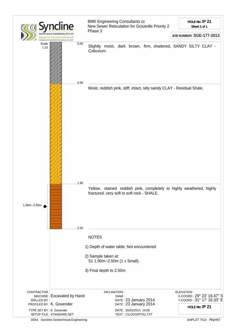
1.90m--2.50m
BMK Engineering Consultants ccNew Sewer Reticulation for Groutville Priority 2Phase 3
HOLE No: IP 21Sheet 1 of 1
HOLE No: IP 21Sheet 1 of 1
HOLE No: IP 21Sheet 1 of 1
HOLE No: IP 21Sheet 1 of 1
JOB NUMBER: SGE-177-2013JOB NUMBER: SGE-177-2013
0.56
0.00
1.90
2.50
Slightly moist, dark brown, firm, shattered, SANDY SILTY CLAY -Colluvium.
Moist, reddish pink, stiff, intact, silty sandy CLAY - Residual Shale.
Yellow, stained reddish pink, completely to highly weathered, highlyfractured, very soft to soft rock - SHALE.
Scale1:15
NOTES
1) Depth of water table: Not encountered.
2) Sample taken at:S1 1.90m--2.50m (1 x Small).
3) Final depth to 2.50m.
CONTRACTOR :MACHINE :
DRILLED BY :PROFILED BY :
TYPE SET BY :SETUP FILE :
Excavated by Hand
K. GovenderK. GovenderSTANDARD.SET
INCLINATION :DIAM :DATE :DATE :
DATE :TEXT :
23 January 201423 January 201426/02/2014 14:09C\LOGS\PITS1.TXT
ELEVATION :X-COORD :Y-COORD :
29° 23’ 16.47" S31° 17’ 16.33" E
dotPLOT 7014 PBpH67D0A4 Syncline Geotechnical Engineering
HOLE No: IP 21HOLE No: IP 21HOLE No: IP 21HOLE No: IP 21
APPENDIX BFebruary 20, 2014
CBR DYNAMIC CONE
PENETROMETER (DCP) TESTS
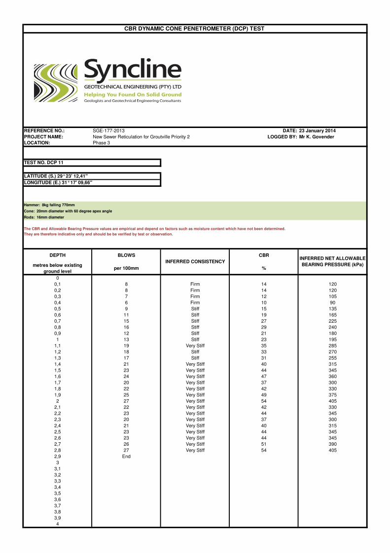
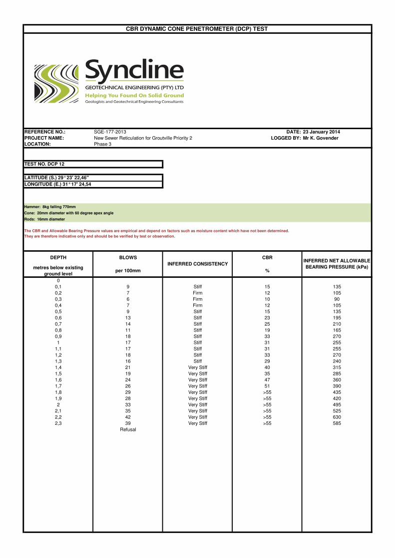
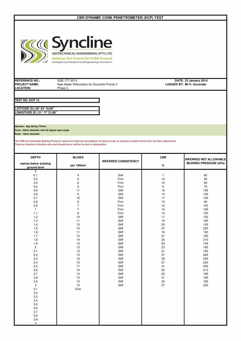
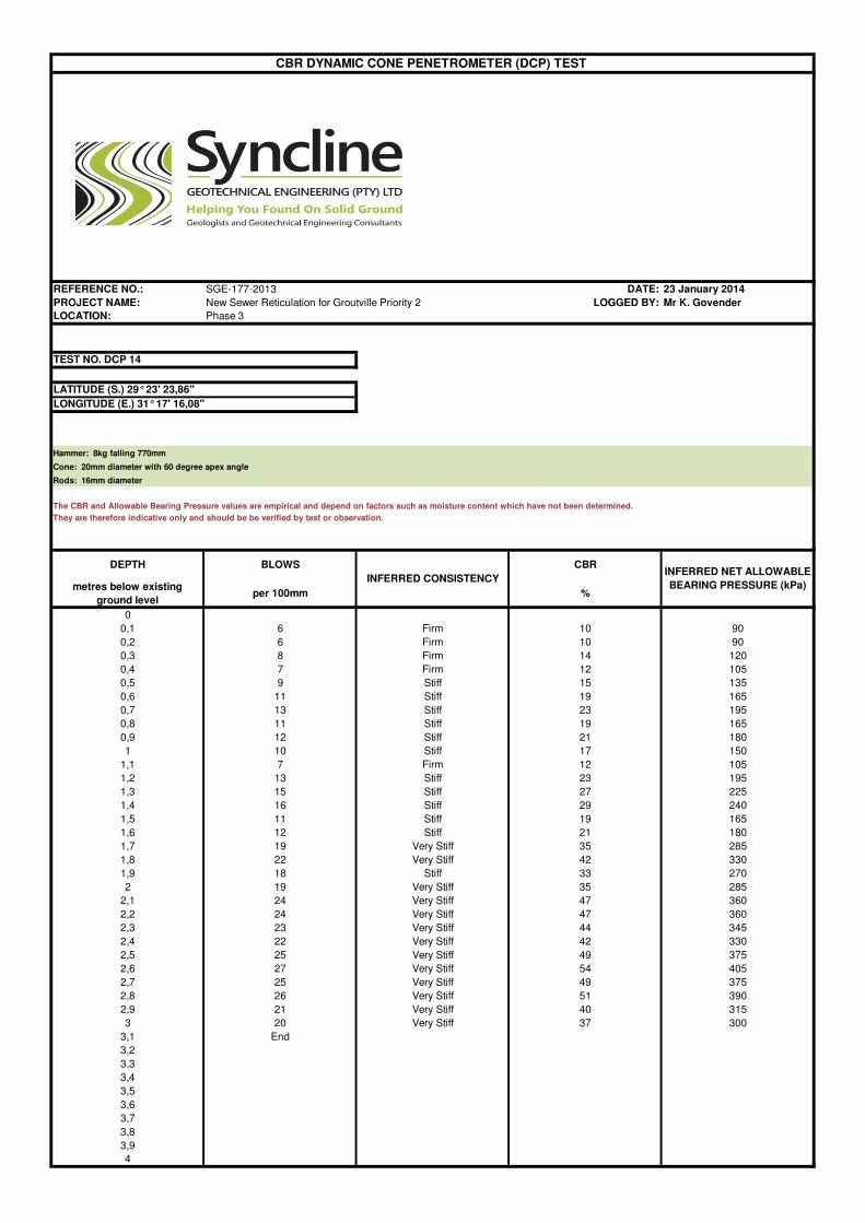
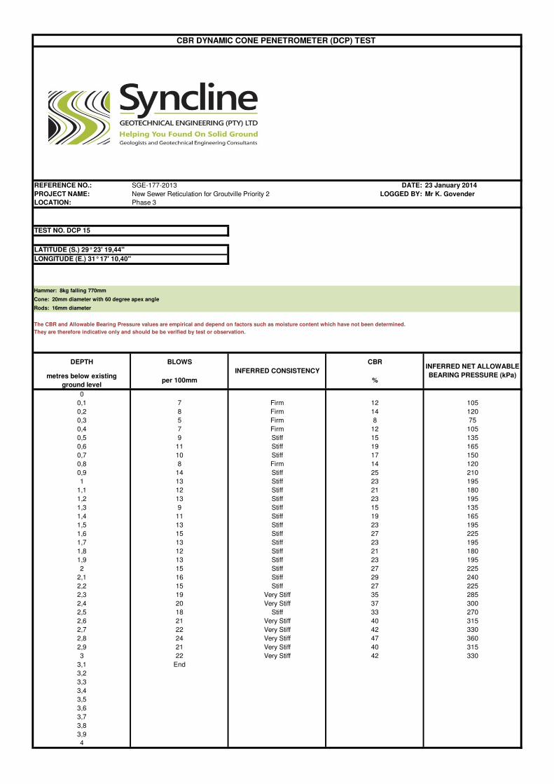
REFERENCE NO.: SGE-177-2013 DATE: 23 January 2014
PROJECT NAME: New Sewer Reticulation for Groutville Priority 2 LOGGED BY: Mr K. Govender
LOCATION: Phase 3
Hammer: 8kg falling 770mm
Cone: 20mm diameter with 60 degree apex angle
Rods: 16mm diameter
The CBR and Allowable Bearing Pressure values are empirical and depend on factors such as moisture content which have not been determined.
They are therefore indicative only and should be be verified by test or observation.
DEPTH BLOWS CBR
metres below existing
ground levelper 100mm %
0
0,1 8 Firm 14 120
0,2 8 Firm 14 120
0,3 7 Firm 12 105
0,4 6 Firm 10 90
0,5 9 Stiff 15 135
0,6 11 Stiff 19 165
0,7 15 Stiff 27 225
0,8 16 Stiff 29 240
0,9 12 Stiff 21 180
1 13 Stiff 23 195
1,1 19 Very Stiff 35 285
1,2 18 Stiff 33 270
1,3 17 Stiff 31 255
1,4 21 Very Stiff 40 315
1,5 23 Very Stiff 44 345
1,6 24 Very Stiff 47 360
1,7 20 Very Stiff 37 300
1,8 22 Very Stiff 42 330
1,9 25 Very Stiff 49 375
2 27 Very Stiff 54 405
2,1 22 Very Stiff 42 330
2,2 23 Very Stiff 44 345
2,3 20 Very Stiff 37 300
2,4 21 Very Stiff 40 315
2,5 23 Very Stiff 44 345
2,6 23 Very Stiff 44 345
2,7 26 Very Stiff 51 390
2,8 27 Very Stiff 54 405
2,9 End
3
3,1
3,2
3,3
3,4
3,5
3,6
3,7
3,8
3,9
4
INFERRED CONSISTENCYINFERRED NET ALLOWABLE
BEARING PRESSURE (kPa)
CBR DYNAMIC CONE PENETROMETER (DCP) TEST
TEST NO. DCP 11
LATITUDE (S.) 29° 23' 12,41"
LONGITUDE (E.) 31° 17' 09,66"
REFERENCE NO.: SGE-177-2013 DATE: 23 January 2014
PROJECT NAME: New Sewer Reticulation for Groutville Priority 2 LOGGED BY: Mr K. Govender
LOCATION: Phase 3
Hammer: 8kg falling 770mm
Cone: 20mm diameter with 60 degree apex angle
Rods: 16mm diameter
The CBR and Allowable Bearing Pressure values are empirical and depend on factors such as moisture content which have not been determined.
They are therefore indicative only and should be be verified by test or observation.
DEPTH BLOWS CBR
metres below existing
ground levelper 100mm %
0
0,1 9 Stiff 15 135
0,2 7 Firm 12 105
0,3 6 Firm 10 90
0,4 7 Firm 12 105
0,5 9 Stiff 15 135
0,6 13 Stiff 23 195
0,7 14 Stiff 25 210
0,8 11 Stiff 19 165
0,9 18 Stiff 33 270
1 17 Stiff 31 255
1,1 17 Stiff 31 255
1,2 18 Stiff 33 270
1,3 16 Stiff 29 240
1,4 21 Very Stiff 40 315
1,5 19 Very Stiff 35 285
1,6 24 Very Stiff 47 360
1,7 26 Very Stiff 51 390
1,8 29 Very Stiff >55 435
1,9 28 Very Stiff >55 420
2 33 Very Stiff >55 495
2,1 35 Very Stiff >55 525
2,2 42 Very Stiff >55 630
2,3 39 Very Stiff >55 585
Refusal
INFERRED CONSISTENCYINFERRED NET ALLOWABLE
BEARING PRESSURE (kPa)
CBR DYNAMIC CONE PENETROMETER (DCP) TEST
TEST NO. DCP 12
LATITUDE (S.) 29° 23' 22,46"
LONGITUDE (E.) 31° 17' 24,54
REFERENCE NO.: SGE-177-2013 DATE: 23 January 2014
PROJECT NAME: New Sewer Reticulation for Groutville Priority 2 LOGGED BY: Mr K. Govender
LOCATION: Phase 3
Hammer: 8kg falling 770mm
Cone: 20mm diameter with 60 degree apex angle
Rods: 16mm diameter
The CBR and Allowable Bearing Pressure values are empirical and depend on factors such as moisture content which have not been determined.
They are therefore indicative only and should be be verified by test or observation.
DEPTH BLOWS CBR
metres below existing
ground levelper 100mm %
0
0,1 4 Soft 7 60
0,2 6 Firm 10 90
0,3 6 Firm 10 90
0,4 5 Firm 8 75
0,5 11 Stiff 19 165
0,6 9 Stiff 15 135
0,7 10 Stiff 17 150
0,8 6 Firm 10 90
0,9 7 Firm 12 105
1 7 Firm 12 105
1,1 8 Firm 14 120
1,2 10 Stiff 17 150
1,3 11 Stiff 19 165
1,4 13 Stiff 23 195
1,5 15 Stiff 27 225
1,6 11 Stiff 19 165
1,7 12 Stiff 21 180
1,8 14 Stiff 25 210
1,9 13 Stiff 23 195
2 13 Stiff 23 195
2,1 12 Stiff 21 180
2,2 15 Stiff 27 225
2,3 16 Stiff 29 240
2,4 15 Stiff 27 225
2,5 17 Stiff 31 255
2,6 14 Stiff 25 210
2,7 13 Stiff 23 195
2,8 12 Stiff 21 180
2,9 13 Stiff 23 195
3 15 Stiff 27 225
3,1 End
3,2
3,3
3,4
3,5
3,6
3,7
3,8
3,9
4
INFERRED CONSISTENCYINFERRED NET ALLOWABLE
BEARING PRESSURE (kPa)
CBR DYNAMIC CONE PENETROMETER (DCP) TEST
TEST NO. DCP 13
LATITUDE (S.) 29° 23' 19,60"
LONGITUDE (E.) 31° 17' 21,69"
REFERENCE NO.: SGE-177-2013 DATE: 23 January 2014
PROJECT NAME: New Sewer Reticulation for Groutville Priority 2 LOGGED BY: Mr K. Govender
LOCATION: Phase 3
Hammer: 8kg falling 770mm
Cone: 20mm diameter with 60 degree apex angle
Rods: 16mm diameter
The CBR and Allowable Bearing Pressure values are empirical and depend on factors such as moisture content which have not been determined.
They are therefore indicative only and should be be verified by test or observation.
DEPTH BLOWS CBR
metres below existing
ground levelper 100mm %
0
0,1 6 Firm 10 90
0,2 6 Firm 10 90
0,3 8 Firm 14 120
0,4 7 Firm 12 105
0,5 9 Stiff 15 135
0,6 11 Stiff 19 165
0,7 13 Stiff 23 195
0,8 11 Stiff 19 165
0,9 12 Stiff 21 180
1 10 Stiff 17 150
1,1 7 Firm 12 105
1,2 13 Stiff 23 195
1,3 15 Stiff 27 225
1,4 16 Stiff 29 240
1,5 11 Stiff 19 165
1,6 12 Stiff 21 180
1,7 19 Very Stiff 35 285
1,8 22 Very Stiff 42 330
1,9 18 Stiff 33 270
2 19 Very Stiff 35 285
2,1 24 Very Stiff 47 360
2,2 24 Very Stiff 47 360
2,3 23 Very Stiff 44 345
2,4 22 Very Stiff 42 330
2,5 25 Very Stiff 49 375
2,6 27 Very Stiff 54 405
2,7 25 Very Stiff 49 375
2,8 26 Very Stiff 51 390
2,9 21 Very Stiff 40 315
3 20 Very Stiff 37 300
3,1 End
3,2
3,3
3,4
3,5
3,6
3,7
3,8
3,9
4
INFERRED CONSISTENCYINFERRED NET ALLOWABLE
BEARING PRESSURE (kPa)
CBR DYNAMIC CONE PENETROMETER (DCP) TEST
TEST NO. DCP 14
LATITUDE (S.) 29° 23' 23,86"
LONGITUDE (E.) 31° 17' 16,08"
REFERENCE NO.: SGE-177-2013 DATE: 23 January 2014
PROJECT NAME: New Sewer Reticulation for Groutville Priority 2 LOGGED BY: Mr K. Govender
LOCATION: Phase 3
Hammer: 8kg falling 770mm
Cone: 20mm diameter with 60 degree apex angle
Rods: 16mm diameter
The CBR and Allowable Bearing Pressure values are empirical and depend on factors such as moisture content which have not been determined.
They are therefore indicative only and should be be verified by test or observation.
DEPTH BLOWS CBR
metres below existing
ground levelper 100mm %
0
0,1 7 Firm 12 105
0,2 8 Firm 14 120
0,3 5 Firm 8 75
0,4 7 Firm 12 105
0,5 9 Stiff 15 135
0,6 11 Stiff 19 165
0,7 10 Stiff 17 150
0,8 8 Firm 14 120
0,9 14 Stiff 25 210
1 13 Stiff 23 195
1,1 12 Stiff 21 180
1,2 13 Stiff 23 195
1,3 9 Stiff 15 135
1,4 11 Stiff 19 165
1,5 13 Stiff 23 195
1,6 15 Stiff 27 225
1,7 13 Stiff 23 195
1,8 12 Stiff 21 180
1,9 13 Stiff 23 195
2 15 Stiff 27 225
2,1 16 Stiff 29 240
2,2 15 Stiff 27 225
2,3 19 Very Stiff 35 285
2,4 20 Very Stiff 37 300
2,5 18 Stiff 33 270
2,6 21 Very Stiff 40 315
2,7 22 Very Stiff 42 330
2,8 24 Very Stiff 47 360
2,9 21 Very Stiff 40 315
3 22 Very Stiff 42 330
3,1 End
3,2
3,3
3,4
3,5
3,6
3,7
3,8
3,9
4
INFERRED CONSISTENCYINFERRED NET ALLOWABLE
BEARING PRESSURE (kPa)
CBR DYNAMIC CONE PENETROMETER (DCP) TEST
TEST NO. DCP 15
LATITUDE (S.) 29° 23' 19,44"
LONGITUDE (E.) 31° 17' 10,40"

REFERENCE NO.: SGE-177-2013 DATE: 23 January 2014
PROJECT NAME: New Sewer Reticulation for Groutville Priority 2 LOGGED BY: Mr K. Govender
LOCATION: Phase 3
Hammer: 8kg falling 770mm
Cone: 20mm diameter with 60 degree apex angle
Rods: 16mm diameter
The CBR and Allowable Bearing Pressure values are empirical and depend on factors such as moisture content which have not been determined.
They are therefore indicative only and should be be verified by test or observation.
DEPTH BLOWS CBR
metres below existing
ground levelper 100mm %
0
0,1 6 Firm 10 90
0,2 7 Firm 12 105
0,3 7 Firm 12 105
0,4 9 Stiff 15 135
0,5 11 Stiff 19 165
0,6 14 Stiff 25 210
0,7 13 Stiff 23 195
0,8 12 Stiff 21 180
0,9 14 Stiff 25 210
1 11 Stiff 19 165
1,1 13 Stiff 23 195
1,2 19 Very Stiff 35 285
1,3 15 Stiff 27 225
1,4 11 Stiff 19 165
1,5 13 Stiff 23 195
1,6 12 Stiff 21 180
1,7 10 Stiff 17 150
1,8 12 Stiff 21 180
1,9 16 Stiff 29 240
2 19 Very Stiff 35 285
2,1 22 Very Stiff 42 330
2,2 21 Very Stiff 40 315
2,3 18 Stiff 33 270
2,4 23 Very Stiff 44 345
2,5 19 Very Stiff 35 285
2,6 17 Stiff 31 255
2,7 16 Stiff 29 240
2,8 18 Stiff 33 270
2,9 17 Stiff 31 255
3 16 Stiff 29 240
3,1 End
3,2
3,3
3,4
3,5
3,6
3,7
3,8
3,9
4
INFERRED CONSISTENCYINFERRED NET ALLOWABLE
BEARING PRESSURE (kPa)
CBR DYNAMIC CONE PENETROMETER (DCP) TEST
TEST NO. DCP 16
LATITUDE (S.) 29° 23' 28,606"
LONGITUDE (E.) 31° 17' 06,73"
REFERENCE NO.: SGE-177-2013 DATE: 23 January 2014
PROJECT NAME: New Sewer Reticulation for Groutville Priority 2 LOGGED BY: Mr K. Govender
LOCATION: Phase 3
Hammer: 8kg falling 770mm
Cone: 20mm diameter with 60 degree apex angle
Rods: 16mm diameter
The CBR and Allowable Bearing Pressure values are empirical and depend on factors such as moisture content which have not been determined.
They are therefore indicative only and should be be verified by test or observation.
DEPTH BLOWS CBR
metres below existing
ground levelper 100mm %
0
0,1 8 Firm 14 120
0,2 6 Firm 10 90
0,3 9 Stiff 15 135
0,4 8 Firm 14 120
0,5 11 Stiff 19 165
0,6 13 Stiff 23 195
0,7 12 Stiff 21 180
0,8 10 Stiff 17 150
0,9 13 Stiff 23 195
1 16 Stiff 29 240
1,1 18 Stiff 33 270
1,2 17 Stiff 31 255
1,3 16 Stiff 29 240
1,4 20 Very Stiff 37 300
1,5 19 Very Stiff 35 285
1,6 19 Very Stiff 35 285
1,7 21 Very Stiff 40 315
1,8 22 Very Stiff 42 330
1,9 23 Very Stiff 44 345
2 24 Very Stiff 47 360
2,1 24 Very Stiff 47 360
2,2 22 Very Stiff 42 330
2,3 25 Very Stiff 49 375
2,4 26 Very Stiff 51 390
2,5 26 Very Stiff 51 390
2,6 17 Stiff 31 255
2,7 19 Very Stiff 35 285
2,8 20 Very Stiff 37 300
2,9 24 Very Stiff 47 360
3 25 Very Stiff 49 375
3,1 End
3,2
3,3
3,4
3,5
3,6
3,7
3,8
3,9
4
INFERRED CONSISTENCYINFERRED NET ALLOWABLE
BEARING PRESSURE (kPa)
CBR DYNAMIC CONE PENETROMETER (DCP) TEST
TEST NO. DCP 17
LATITUDE (S.) 29° 23' 24,13"
LONGITUDE (E.) 31° 17' 03,74"

REFERENCE NO.: SGE-177-2013 DATE: 23 January 2014
PROJECT NAME: New Sewer Reticulation for Groutville Priority 2 LOGGED BY: Mr K. Govender
LOCATION: Phase 3
Hammer: 8kg falling 770mm
Cone: 20mm diameter with 60 degree apex angle
Rods: 16mm diameter
The CBR and Allowable Bearing Pressure values are empirical and depend on factors such as moisture content which have not been determined.
They are therefore indicative only and should be be verified by test or observation.
DEPTH BLOWS CBR
metres below existing
ground levelper 100mm %
0
0,1 5 Firm 8 75
0,2 5 Firm 8 75
0,3 4 Soft 7 60
0,4 6 Firm 10 90
0,5 8 Firm 14 120
0,6 7 Firm 12 105
0,7 9 Stiff 15 135
0,8 8 Firm 14 120
0,9 8 Firm 14 120
1 9 Stiff 15 135
1,1 11 Stiff 19 165
1,2 13 Stiff 23 195
1,3 10 Stiff 17 150
1,4 14 Stiff 25 210
1,5 17 Stiff 31 255
1,6 15 Stiff 27 225
1,7 13 Stiff 23 195
1,8 15 Stiff 27 225
1,9 15 Stiff 27 225
2 17 Stiff 31 255
2,1 21 Very Stiff 40 315
2,2 19 Very Stiff 35 285
2,3 23 Very Stiff 44 345
2,4 27 Very Stiff 54 405
2,5 25 Very Stiff 49 375
2,6 26 Very Stiff 51 390
2,7 24 Very Stiff 47 360
2,8 23 Very Stiff 44 345
2,9 27 Very Stiff 54 405
3 25 Very Stiff 49 375
3,1
3,2
3,3
3,4
3,5
3,6
3,7
3,8
3,9
4
INFERRED CONSISTENCYINFERRED NET ALLOWABLE
BEARING PRESSURE (kPa)
CBR DYNAMIC CONE PENETROMETER (DCP) TEST
TEST NO. DCP 21
LATITUDE (S.) 29° 23' 16,47"
LONGITUDE (E.) 31° 17' 16,33"

APPENDIX CFebruary 20, 2014
RESULTS OF LABORATORY
TESTS

Client : SYNCLINE GEOTECHNICAL ENGINEERING (Pty) Ltd Our Ref. No. : 7963/14
Project : NEW SEWER RETICULATION, GROUTVILLE, KWADUKUZA Your Ref. No. :- Attention : Mr S. Pather Date Reported : 13.02.14
D1092 D1083 D1084 D1085
IP11 IP11 IP13 IP14
0.00 - 0.50 0.50 - 0.90 0.20 - 1.50 1.07 - 2.00
Moderate to dark grey, slightly Dark red to reddish brown, Light brown, slightly, Yellowish brn, mottled orange,
gravelly,silty SAND - Colluvium SANDY SILTY CLAY to silty silty SAND - Alluvium silty CLAY -
sandy CLAY - Residual Shale Residual Shale
100 100100 100 100100 99 100 100
98 99 100 10095 90 98 9569 64 19 91
LL% 42 41 NP 44P.I. 13 13 NP 21
LS% 6,5 6,5 NP 10,5GM 0,38 0,47 0,83 0,14
H.R.B.*
T.R.H. 14*
LIMITS
(TMH A2&A3)
CLASSIFI -
CATION
75,0
53,0
2,00
(TMH A1a)
(mm)
37,5
19,0
TEST REPORT
SAMPLE INFORMATION & PROPERTIES
SAMPLE No.
CONTAINER USED FOR SAMPLING
SIEVE ANALYSIS
4,75
13,2
SIZE / WEIGHT OF SAMPLE
MOISTURE CONDITION OF
SAMPLE ON ARRIVAL
ROAD No. OR NAME
HOLE No. / Km. / CHAINAGE
DATE SAMPLED
LAYER TESTED / SAMPLED FROM DEPTH (M)
CLIENTS MARKING
(COLOUR & TYPE)
PROCTOR ITS : DRY (kPa)
63,0
COLTO*
(TMH A13T) 97%
(TMH A7) MDD(KG/M3)
C.B.R. % SWELL
95%
(TMH A8)
0,075
SAMPLED ACCORDING TO
ENVIRONMENTAL CONDITION
WHEN SAMPLED
MOD ITS : DRY (kPa) (A16T)
MOD AASHTO OMC%
ATTERBERG
93%
90%
REMARKS & NOTES
DESCRIPTION OF SAMPLE
TEST TYPE
Please find the attached test results for the sample/s as submitted to and tested by Roadlab (PTY)Ltd.
The unambiguous description of the sample/s as received are as follows :
U.C.S. 98%
COMP MC
100%
0,425
C.B.R.
GRADING ANALYSIS - % PASSING SIEVES (TMH1 1986 : METHOD A1 (a)
26,5
THE MAXIMUM DRY DENSITY & OPTIMUM MOISTURE CONTENT/CALIFORNIA BEARING RATIO(TMH1 1986 : METHOD A7,A8)
SAMPLED BY
HOT
PLASTIC BAGS
MOIST
±70 KG
INDICATORROADLAB
TMH 5
23.01.14N/A
PHASE 3
MASTERS\SOIL\CBR,UCS REF 0 2004/01/28
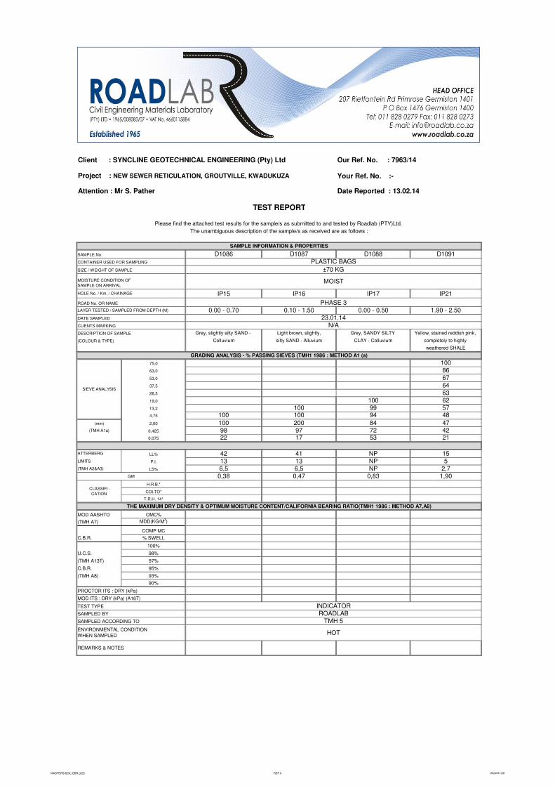
Client : SYNCLINE GEOTECHNICAL ENGINEERING (Pty) Ltd Our Ref. No. : 7963/14
Project : NEW SEWER RETICULATION, GROUTVILLE, KWADUKUZA Your Ref. No. :- Attention : Mr S. Pather Date Reported : 13.02.14
D1086 D1087 D1088 D1091
IP15 IP16 IP17 IP21
0.00 - 0.70 0.10 - 1.50 0.00 - 0.50 1.90 - 2.50
Grey, slightly silty SAND - Light brown, slightly, Grey, SANDY SILTY Yellow, stained reddish pink,
Colluvium silty SAND - Alluvium CLAY - Colluvium completely to highly
weathered SHALE
10086676463
100 62100 99 57
100 100 94 48
100 200 84 4798 97 72 4222 17 53 21
LL% 42 41 NP 15P.I. 13 13 NP 5
LS% 6,5 6,5 NP 2,7GM 0,38 0,47 0,83 1,90
H.R.B.*
T.R.H. 14*
LIMITS
(TMH A2&A3)
CLASSIFI -
CATION
75,0
53,0
2,00
(TMH A1a)
(mm)
37,5
19,0
TEST REPORT
SAMPLE INFORMATION & PROPERTIES
SAMPLE No.
CONTAINER USED FOR SAMPLING
SIEVE ANALYSIS
4,75
13,2
SIZE / WEIGHT OF SAMPLE
MOISTURE CONDITION OF
SAMPLE ON ARRIVAL
ROAD No. OR NAME
HOLE No. / Km. / CHAINAGE
DATE SAMPLED
LAYER TESTED / SAMPLED FROM DEPTH (M)
CLIENTS MARKING
(COLOUR & TYPE)
PROCTOR ITS : DRY (kPa)
63,0
COLTO*
(TMH A13T) 97%
(TMH A7) MDD(KG/M3)
C.B.R. % SWELL
95%
(TMH A8)
0,075
SAMPLED ACCORDING TO
ENVIRONMENTAL CONDITION
WHEN SAMPLED
MOD ITS : DRY (kPa) (A16T)
MOD AASHTO OMC%
ATTERBERG
93%
90%
REMARKS & NOTES
DESCRIPTION OF SAMPLE
TEST TYPE
Please find the attached test results for the sample/s as submitted to and tested by Roadlab (PTY)Ltd.
The unambiguous description of the sample/s as received are as follows :
U.C.S. 98%
COMP MC
100%
0,425
C.B.R.
GRADING ANALYSIS - % PASSING SIEVES (TMH1 1986 : METHOD A1 (a)
26,5
THE MAXIMUM DRY DENSITY & OPTIMUM MOISTURE CONTENT/CALIFORNIA BEARING RATIO(TMH1 1986 : METHOD A7,A8)
SAMPLED BY
HOT
PLASTIC BAGS
MOIST
±70 KG
INDICATORROADLAB
TMH 5
23.01.14N/A
PHASE 3
MASTERS\SOIL\CBR,UCS REF 0 2004/01/28
FIGURE 1February 20, 2014
SITE PLAN
(showing field test positions)
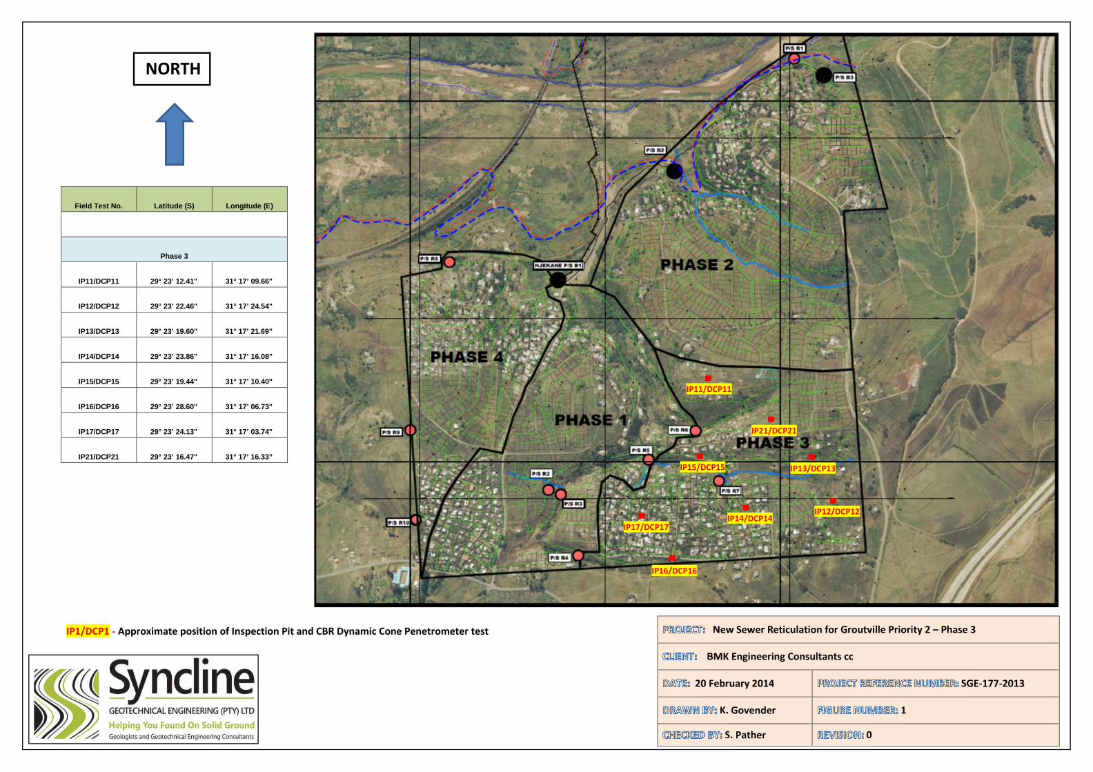
IP1/DCP1 - Approximate position of Inspection Pit and CBR Dynamic Cone Penetrometer test New Sewer Reticulation for Groutville Priority 2 – Phase 3
BMK Engineering Consultants cc
20 February 2014 SGE-177-2013
K. Govender 1
S. Pather 0
Field Test No. Latitude (S) Longitude (E)
Phase 3
IP11/DCP11 29° 23’ 12.41" 31° 17’ 09.66"
IP12/DCP12 29° 23’ 22.46" 31° 17’ 24.54"
IP13/DCP13 29° 23’ 19.60" 31° 17’ 21.69”
IP14/DCP14 29° 23’ 23.86" 31° 17’ 16.08"
IP15/DCP15 29° 23’ 19.44" 31° 17’ 10.40"
IP16/DCP16 29° 23’ 28.60" 31° 17’ 06.73"
IP17/DCP17 29° 23’ 24.13" 31° 17’ 03.74"
IP21/DCP21 29° 23’ 16.47" 31° 17’ 16.33”
NORTH
IP15/DCP15
IP17/DCP17
IP21/DCP21
IP13/DCP13
IP16/DCP16
IP14/DCP14IP12/DCP12
IP11/DCP11

FIGURE 2February 20, 2014
GEOLOGY OF STUDY AREA
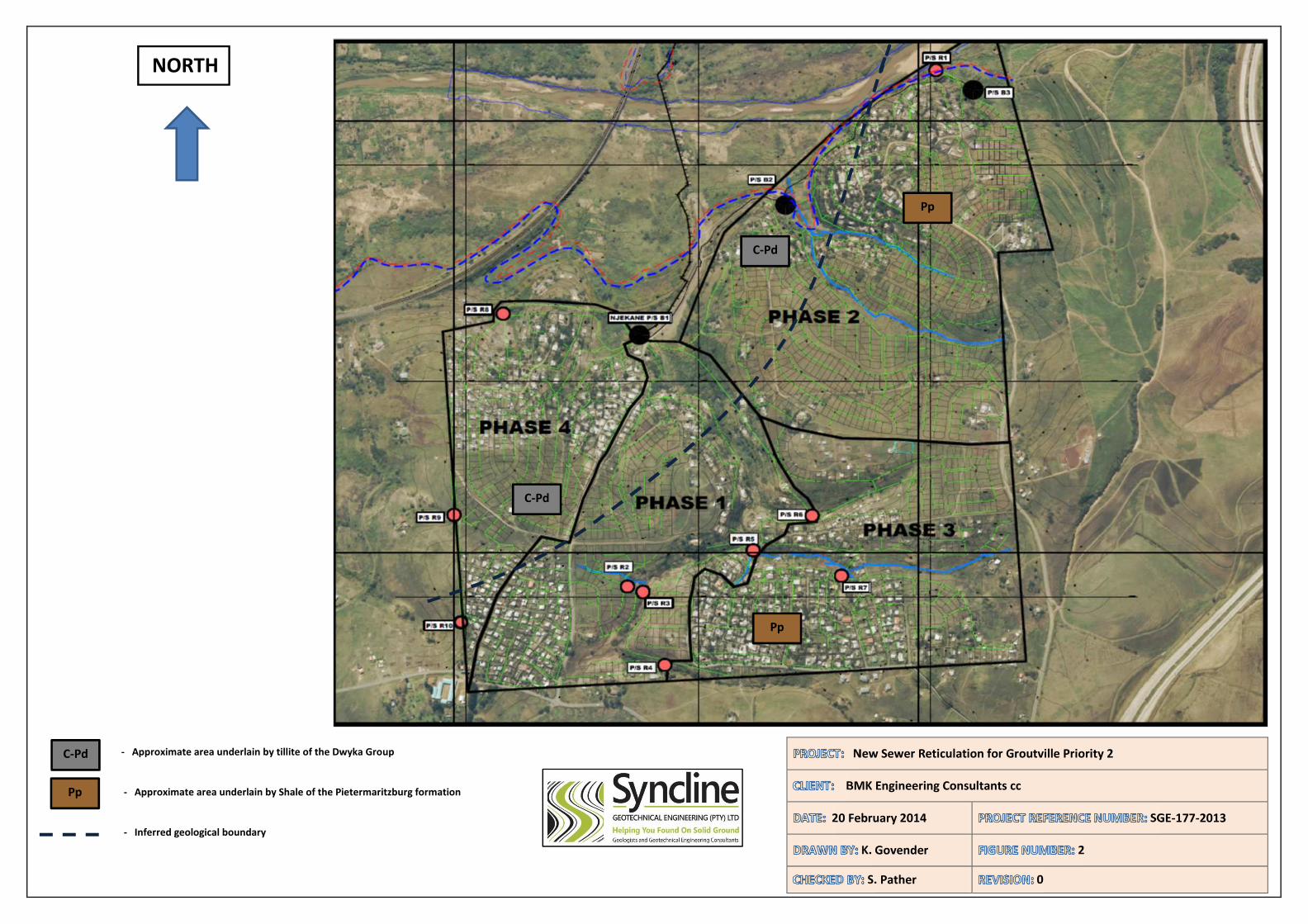
- Approximate area underlain by tillite of the Dwyka Group
- Approximate area underlain by Shale of the Pietermaritzburg formation
- Inferred geological boundary
New Sewer Reticulation for Groutville Priority 2
BMK Engineering Consultants cc
20 February 2014 SGE-177-2013
K. Govender 2
S. Pather 0
NORTH
C-Pd
Pp
C-Pd
Pp
Pp
C-Pd