Embed Size (px)
Citation preview
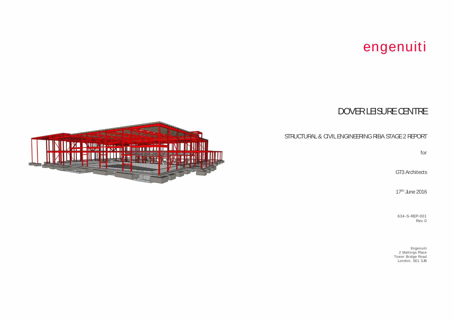
engenuiti
DOVER LEISURE CENTRE
STRUCTURAL & CIVIL ENGINEERING RIBA STAGE 2 REPORT
for
GT3 Architects
17th June 2016
634-S-REP-001 Rev 0
Engenuiti 2 Maltings Place
Tower Bridge Road London, SE1 3JB
Dover Leisure Centre Structural & Civil Engineering RIBA Stage 2 Report engenuiti
Structural & Civil Engineering RIBA Stage 2 Report Date: 17 June 2016 Rev: 0 Page 2
STRUCTURAL & CIVIL ENGINEERING RIBA STAGE 2 REPORT CONTENTS Section Item Page
1 EXECUTIVE SUMMARY 3
2 INTRODUCTION 4
3 DESIGN BRIEF & STRUCTURAL FRAMING OPTIONS 5
4 SWIMMING POOL CONSTRUCTION OPTIONS 8
5 SITE CONDITIONS 10
6 SUBSTRUCTURE & FOUNDATIONS 12
7 SUPERSTRUCTURE 14
8 BUILDING ENVELOPE 15
9 CIVIL ENGINEERING WORKS 17
10 SUSTAINABILITY 23
11 FURTHER STUDIES & INVESTIGATIONS REQUIRED 26
APPENDIX A Structural & Civil Engineering Design Criteria & Materials Report
APPENDIX B Structural Engineering Sketches
APPENDIX C Long Span Roof Studies
Revision History
Rev Date Purpose/Status Document Ref. Comments 00 24 June 2016 Draft 633-S-REP-001 Issued for Information
Prepared by: Reviewed & Approved by:
Chris Law
Sarah Curran
Paul Grimes
Senior Engineer Associate Director This document is copyright © The Engenuiti Partnership LLP and is prepared for use by GT3 Architects Limited. The document may not be used by any party, copied or distributed without written approval from The Engenuiti Partnership LLP.
Dover Leisure Centre Structural & Civil Engineering RIBA Stage 2 Report engenuiti
Structural & Civil Engineering RIBA Stage 2 Report Date: 17 June 2016 Rev: 0 Page 3
1 EXECUTIVE SUMMARY 1.1.1 Engenuiti has been appointed by GT3 Architects to provide civil and structural engineering design
services for the proposed new leisure centre for Dover.
1.1.2 The purpose of this Structural & Civil Engineering Feasibility RIBA Stage 2 Report is to describe the civil
& structural engineering concept design of the proposed development to support the preliminary cost
estimates for the project.
1.1.3 The proposed leisure centre is located in Whitfield, Dover. The site postcode is CT16 3FH. The site
location is south of Honeywood Parkway and east of The Glenmore Centre.
1.1.4 The site is currently a greenfield location bounded by Honeywood Parkway and a spur road to the east
of the site.
1.1.5 The proposed leisure centre is a new build facility. The new facility will be designed around the
following accommodation mix:
• 8 lane 25m pool
• Learner pool with moveable floor
• Wet changing village
• Activity zone around a new café space
• 4 court sports hall with associated changing
• Treatment rooms
• Gymnasium
• 2 large dance studios
• Spinning studio.
1.1.6 The proposed building superstructure can be conceptually split into four key components as follows:
• Long-span roof structures over swimming pools, sports hall and studios (column free areas)
• Floor slabs to studio and office spaces supported on an regular grid of vertical support
• Secondary structure to façade and building envelope
• Swimming Pool structures
1.1.7 Several structural framing solutions can be applied to the proposed architectural form. The long span
roofs can be framed using cellular steel beams, steel trusses or glulaminated timber beams or trusses.
The floor slabs to studio and office areas can be frames using steel columns and beams with composite
reinforced concrete slabs cast on metal deck or using precast concrete soffit panel systems. Cross
Laminated Timber (CLT) floor options are also possible.
1.1.8 Secondary structural framing to building envelope can be through the use of metal decks, timber
cassettes, composite panel systems, concrete block walls, cold formed steel backing systems and CLT
panels.
1.1.9 The swimming pool structure can be constructed out of in situ reinforced concrete, stainless steel
systems or sprayed concrete.
1.1.10 The British Geological Survey (BGS) online map indicates that the sites bedrock geology is Margate
Chalk Member. The sites superficial deposits are of Clay with flints formation, consisting of clay, silt
sand and gravel.
1.1.11 Based on the desktop study of the local geology and borehole data available on the BGS website we
suggest that the proposed structure and ground conditions may be suitable for shallow pads and ground
bearing slabs founded on the chalk.
1.1.12 Our experience of leisure centre construction suggests that shallow foundations and a ground bearing
pool structure are the most favoured starting point from a cost perspective but that allowance should
be made for a piled foundation solution until further ground information is available.
1.1.13 Applications and consultation will be required to Southern to agree a method of discharge and flow rate
from the swimming pools. Additional applications will be required to Southern Water if connecting to the
public sewer network and also to the Environment Agency if the final proposal incorporates discharge to
ground.
1.1.14 As the development is considered “Major”, the Local Lead Flood Authority: Kent County Council SuDS
pro-forma will need to be completed as part of the planning application process.
1.1.15 We will investigate the feasibility of discharging surface water to ground through a soakaway,
incorporating results from infiltration testing. Additional SuDS measures will also be studied and
considered further at the next design stage.
1.1.16 At this stage we suggest using a baseline structural option of a steel frame with long span truss over
the swimming pool and long span cell beam roof, shallow RC foundations and in situ RC swimming
pool. We have progressed the cladding design using a timber cassette envelope solution.
Dover Leisure Centre Structural & Civil Engineering RIBA Stage 2 Report engenuiti
Structural & Civil Engineering RIBA Stage 2 Report Date: 17 June 2016 Rev: 0 Page 4
2 INTRODUCTION
2.1 General
2.1.1 Engenuiti has been appointed by GT3 Architects to provide civil and structural engineering design
services for the proposed new leisure centre for Dover District Council.
2.1.2 The purpose of this Structural & Civil Engineering Feasibility RIBA Stage 2 Report is to describe the
civil & structural engineering concept design of the proposed development to support the preliminary
cost estimates for the project.
2.1.3 This report has been produced for the exclusive use of GT3 Architects and should not be used in whole
or in part by any third parties without the express permission of Engenuiti in writing.
2.1.4 This report should not be relied upon exclusively for decision making purposes and should be read in
conjunction with other documents and drawings produced by the design team.
2.2 Proposed Development
2.2.1 The proposed leisure centre is located in Dover, Kent. The site location is near the Whitfield
Interchange just south of the main A2 road and is bounded by Honeywood Parkway.
2.2.2 The site is currently a greenfield location bounded by Honeywood Parkway and a spur road to the east
of the site.
2.2.3 The proposed leisure centre is a new build facility. The new facility will be designed around the
following accommodation mix:
• 8 lane 25m pool
• Learner pool with moveable floor
• Wet changing village
• Activity zone around a new café space
• 4 court sports hall with associated changing
• Treatment rooms
• Gymnasium
• 2 large dance studios
• Spinning studio.
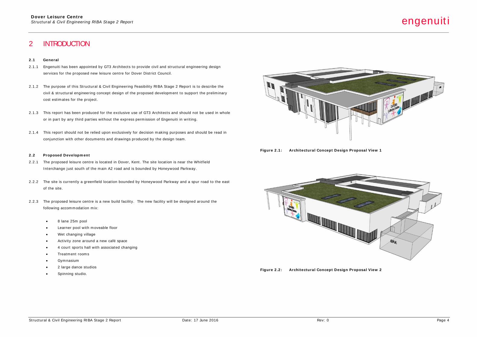
Figure 2.1: Architectural Concept Design Proposal View 1
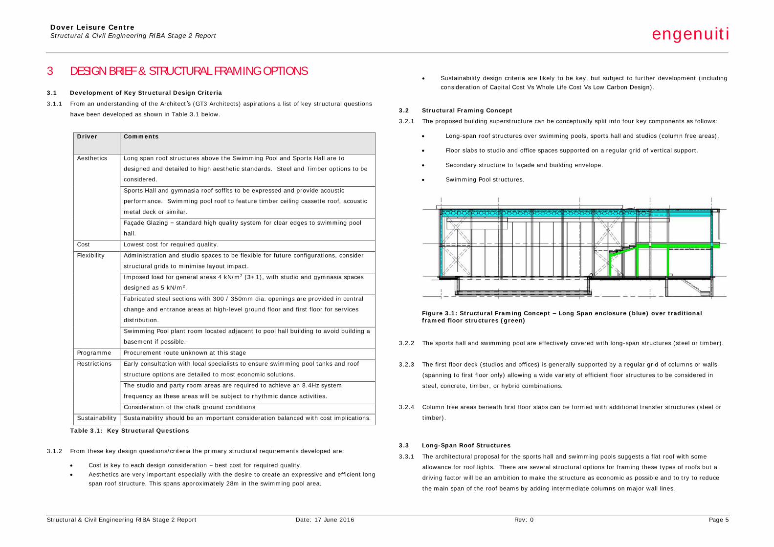
Figure 2.2: Architectural Concept Design Proposal View 2
Dover Leisure Centre Structural & Civil Engineering RIBA Stage 2 Report engenuiti
Structural & Civil Engineering RIBA Stage 2 Report Date: 17 June 2016 Rev: 0 Page 5
3 DESIGN BRIEF & STRUCTURAL FRAMING OPTIONS
3.1 Development of Key Structural Design Criteria
3.1.1 From an understanding of the Architect’s (GT3 Architects) aspirations a list of key structural questions
have been developed as shown in Table 3.1 below.
Driver Comments
Aesthetics Long span roof structures above the Swimming Pool and Sports Hall are to
designed and detailed to high aesthetic standards. Steel and Timber options to be
considered.
Sports Hall and gymnasia roof soffits to be expressed and provide acoustic
performance. Swimming pool roof to feature timber ceiling cassette roof, acoustic
metal deck or similar.
Façade Glazing – standard high quality system for clear edges to swimming pool
hall.
Cost Lowest cost for required quality.
Flexibility Administration and studio spaces to be flexible for future configurations, consider
structural grids to minimise layout impact.
Imposed load for general areas 4 kN/m2 (3+1), with studio and gymnasia spaces
designed as 5 kN/m2.
Fabricated steel sections with 300 / 350mm dia. openings are provided in central
change and entrance areas at high-level ground floor and first floor for services
distribution.
Swimming Pool plant room located adjacent to pool hall building to avoid building a
basement if possible.
Programme Procurement route unknown at this stage
Restrictions Early consultation with local specialists to ensure swimming pool tanks and roof
structure options are detailed to most economic solutions.
The studio and party room areas are required to achieve an 8.4Hz system
frequency as these areas will be subject to rhythmic dance activities.
Consideration of the chalk ground conditions
Sustainability Sustainability should be an important consideration balanced with cost implications.
Table 3.1: Key Structural Questions
3.1.2 From these key design questions/criteria the primary structural requirements developed are:
• Cost is key to each design consideration – best cost for required quality. • Aesthetics are very important especially with the desire to create an expressive and efficient long
span roof structure. This spans approximately 28m in the swimming pool area.
• Sustainability design criteria are likely to be key, but subject to further development (including
consideration of Capital Cost Vs Whole Life Cost Vs Low Carbon Design).
3.2 Structural Framing Concept
3.2.1 The proposed building superstructure can be conceptually split into four key components as follows:
• Long-span roof structures over swimming pools, sports hall and studios (column free areas).
• Floor slabs to studio and office spaces supported on a regular grid of vertical support.
• Secondary structure to façade and building envelope.
• Swimming Pool structures.
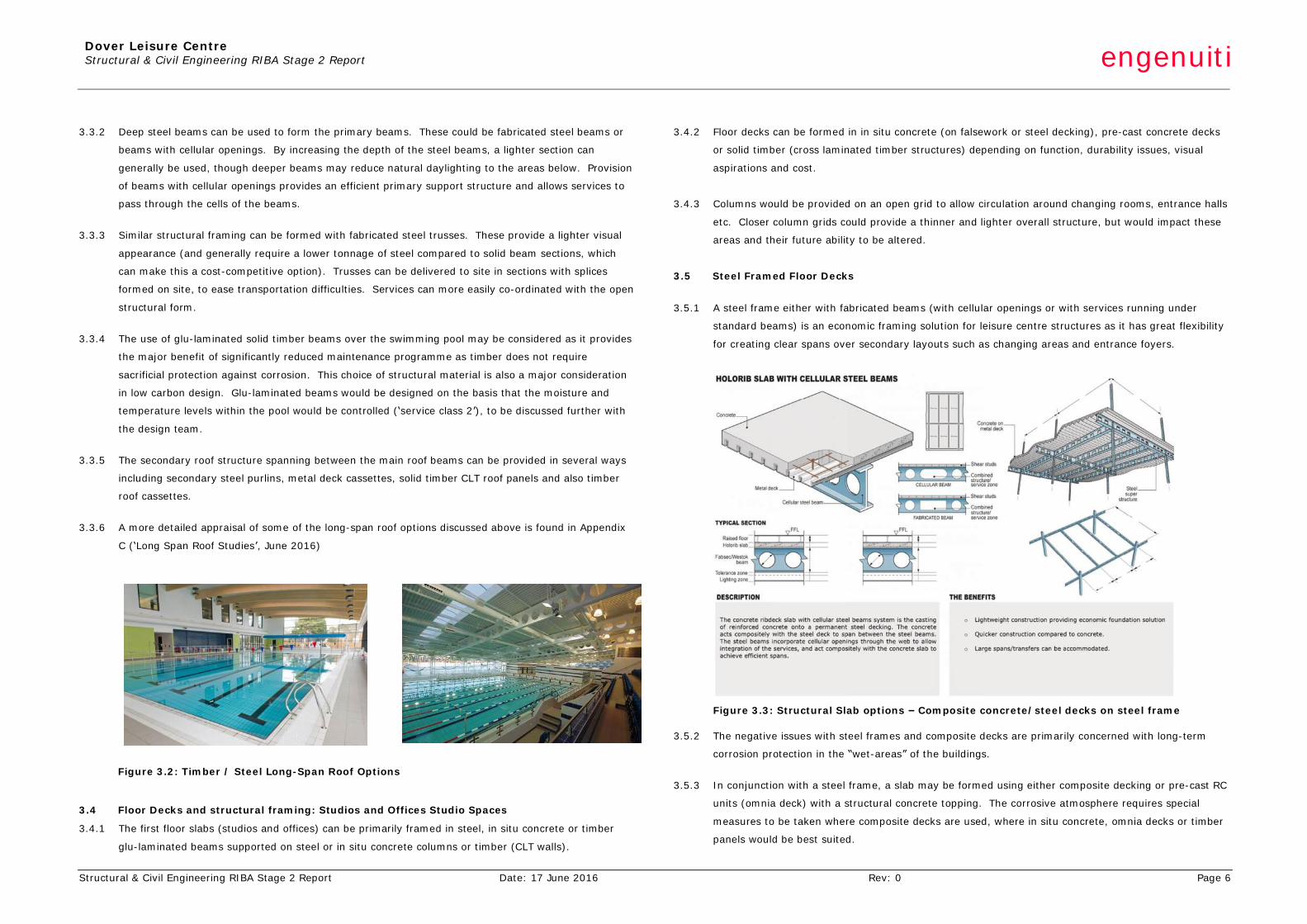
Figure 3.1: Structural Framing Concept – Long Span enclosure (blue) over traditional framed floor structures (green)
3.2.2 The sports hall and swimming pool are effectively covered with long-span structures (steel or timber).
3.2.3 The first floor deck (studios and offices) is generally supported by a regular grid of columns or walls
(spanning to first floor only) allowing a wide variety of efficient floor structures to be considered in
steel, concrete, timber, or hybrid combinations.
3.2.4 Column free areas beneath first floor slabs can be formed with additional transfer structures (steel or
timber).
3.3 Long-Span Roof Structures
3.3.1 The architectural proposal for the sports hall and swimming pools suggests a flat roof with some
allowance for roof lights. There are several structural options for framing these types of roofs but a
driving factor will be an ambition to make the structure as economic as possible and to try to reduce
the main span of the roof beams by adding intermediate columns on major wall lines.
Dover Leisure Centre Structural & Civil Engineering RIBA Stage 2 Report engenuiti
Structural & Civil Engineering RIBA Stage 2 Report Date: 17 June 2016 Rev: 0 Page 6
3.3.2 Deep steel beams can be used to form the primary beams. These could be fabricated steel beams or
beams with cellular openings. By increasing the depth of the steel beams, a lighter section can
generally be used, though deeper beams may reduce natural daylighting to the areas below. Provision
of beams with cellular openings provides an efficient primary support structure and allows services to
pass through the cells of the beams.
3.3.3 Similar structural framing can be formed with fabricated steel trusses. These provide a lighter visual
appearance (and generally require a lower tonnage of steel compared to solid beam sections, which
can make this a cost-competitive option). Trusses can be delivered to site in sections with splices
formed on site, to ease transportation difficulties. Services can more easily co-ordinated with the open
structural form.
3.3.4 The use of glu-laminated solid timber beams over the swimming pool may be considered as it provides
the major benefit of significantly reduced maintenance programme as timber does not require
sacrificial protection against corrosion. This choice of structural material is also a major consideration
in low carbon design. Glu-laminated beams would be designed on the basis that the moisture and
temperature levels within the pool would be controlled (‘service class 2’), to be discussed further with
the design team.
3.3.5 The secondary roof structure spanning between the main roof beams can be provided in several ways
including secondary steel purlins, metal deck cassettes, solid timber CLT roof panels and also timber
roof cassettes.
3.3.6 A more detailed appraisal of some of the long-span roof options discussed above is found in Appendix
C (‘Long Span Roof Studies’, June 2016)
Figure 3.2: Timber / Steel Long-Span Roof Options
3.4 Floor Decks and structural framing: Studios and Offices Studio Spaces
3.4.1 The first floor slabs (studios and offices) can be primarily framed in steel, in situ concrete or timber
glu-laminated beams supported on steel or in situ concrete columns or timber (CLT walls).
3.4.2 Floor decks can be formed in in situ concrete (on falsework or steel decking), pre-cast concrete decks
or solid timber (cross laminated timber structures) depending on function, durability issues, visual
aspirations and cost.
3.4.3 Columns would be provided on an open grid to allow circulation around changing rooms, entrance halls
etc. Closer column grids could provide a thinner and lighter overall structure, but would impact these
areas and their future ability to be altered.
3.5 Steel Framed Floor Decks
3.5.1 A steel frame either with fabricated beams (with cellular openings or with services running under
standard beams) is an economic framing solution for leisure centre structures as it has great flexibility
for creating clear spans over secondary layouts such as changing areas and entrance foyers.
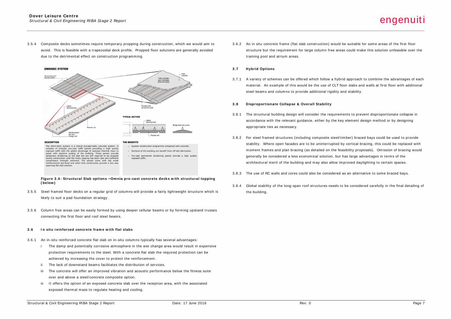
Figure 3.3: Structural Slab options – Composite concrete/steel decks on steel frame
3.5.2 The negative issues with steel frames and composite decks are primarily concerned with long-term
corrosion protection in the “wet-areas” of the buildings.
3.5.3 In conjunction with a steel frame, a slab may be formed using either composite decking or pre-cast RC
units (omnia deck) with a structural concrete topping. The corrosive atmosphere requires special
measures to be taken where composite decks are used, where in situ concrete, omnia decks or timber
panels would be best suited.
Dover Leisure Centre Structural & Civil Engineering RIBA Stage 2 Report engenuiti
Structural & Civil Engineering RIBA Stage 2 Report Date: 17 June 2016 Rev: 0 Page 7
3.5.4 Composite decks sometimes require temporary propping during construction, which we would aim to
avoid. This is feasible with a trapezoidal deck profile. Propped floor solutions are generally avoided
due to the detrimental effect on construction programming.
Figure 3.4: Structural Slab options –Omnia pre-cast concrete decks with structural topping (below)
3.5.5 Steel framed floor decks on a regular grid of columns will provide a fairly lightweight structure which is
likely to suit a pad foundation strategy.
3.5.6 Column free areas can be easily formed by using deeper cellular beams or by forming upstand trusses
connecting the first floor and roof steel beams.
3.6 In situ reinforced concrete frame with flat slabs
3.6.1 An in-situ reinforced concrete flat slab on in-situ columns typically has several advantages:
i The damp and potentially corrosive atmosphere in the wet change area would result in expensive
protection requirements to the steel. With a concrete flat slab the required protection can be
achieved by increasing the cover to protect the reinforcement.
ii The lack of downstand beams facilitates the distribution of services.
iii The concrete will offer an improved vibration and acoustic performance below the fitness suite
over and above a steel/concrete composite option.
iv It offers the option of an exposed concrete slab over the reception area, with the associated
exposed thermal mass to regulate heating and cooling.
3.6.2 An in situ concrete frame (flat slab construction) would be suitable for some areas of the first floor
structure but the requirement for large column free areas could make this solution unfeasible over the
training pool and atrium areas.
3.7 Hybrid Options
3.7.1 A variety of schemes can be offered which follow a hybrid approach to combine the advantages of each
material. An example of this would be the use of CLT floor slabs and walls at first floor with additional
steel beams and columns to provide additional rigidity and stability.
3.8 Disproportionate Collapse & Overall Stability
3.8.1 The structural building design will consider the requirements to prevent disproportionate collapse in
accordance with the relevant guidance, either by the key element design method or by designing
appropriate ties as necessary.
3.8.2 For steel framed structures (including composite steel/timber) braced bays could be used to provide
stability. Where open facades are to be uninterrupted by vertical bracing, this could be replaced with
moment frames and plan bracing (as detailed on the feasibility proposals). Omission of bracing would
generally be considered a less economical solution, but has large advantages in terms of the
architectural merit of the building and may also allow improved daylighting to certain spaces.
3.8.3 The use of RC walls and cores could also be considered as an alternative to some braced bays.
3.8.4 Global stability of the long-span roof structures needs to be considered carefully in the final detailing of
the building.
Dover Leisure Centre Structural & Civil Engineering RIBA Stage 2 Report engenuiti
Structural & Civil Engineering RIBA Stage 2 Report Date: 17 June 2016 Rev: 0 Page 8
4 SWIMMING POOL CONSTRUCTION OPTIONS
4.1 Swimming Pool Construction
4.1.1 The approach to the construction of the swimming pools is a key consideration in the design of any
‘wet side’ leisure centre. Likewise, careful consideration must be given to the implications of
chlorinated pool water in selecting structural materials and protection systems for the pool hall
structural framing. These issues are further discussed below.
4.2 Types of Swimming Pool Construction
4.2.1 The types of pool construction most likely to be suitable for a ground floor level pool in a leisure centre
context are:
1(a) Shuttered in-situ reinforced concrete to BS 8007 / BS EN 1992, part 3.
This is reinforced concrete which is detailed so that it is capable of acting as a water-retaining
structure. This detailing extends to the use of hydrophilic strips or waterbars at joints and the
arrangement of reinforcement to restrict crack widths (usually to 0.2mm). A water resisting
additive may also be employed in the concrete mix.
1(b) Sprayed concrete (shotcrete or gunite)
This is concrete which is applied pneumatically through the use of a pump or hose or nozzle.
The wet concrete is sprayed over the reinforcement cage to form a continuous wall with
minimal construction joints. Mixes with lower water content can be employed than is the case
for conventional cast in-situ concrete, enabling the use of fewer joints.
2(a) Stainless steel side walls, with structural steel back framing, bolted down onto reinforced
concrete slab and lined internally with PVC membrane. An example of this is the system
supplied by Myrtha.
2(b) Stainless steel side walls and floors, with structural steel back framing and welded seams.
4.2.2 Other forms of pool construction which are unlikely to be appropriate in the leisure centre context
include:
3 Concrete blockwork formwork filled with reinforced concrete
Used primarily for private and hotel pools. Robust detailing would depend on specialist input.
4 Reinforced concrete, not designed to BS 8007, but internally tanked
Not recommended due to potential risk of damage to internal membrane, e.g. via thermal
shock
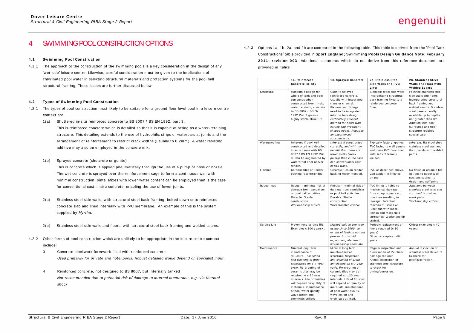
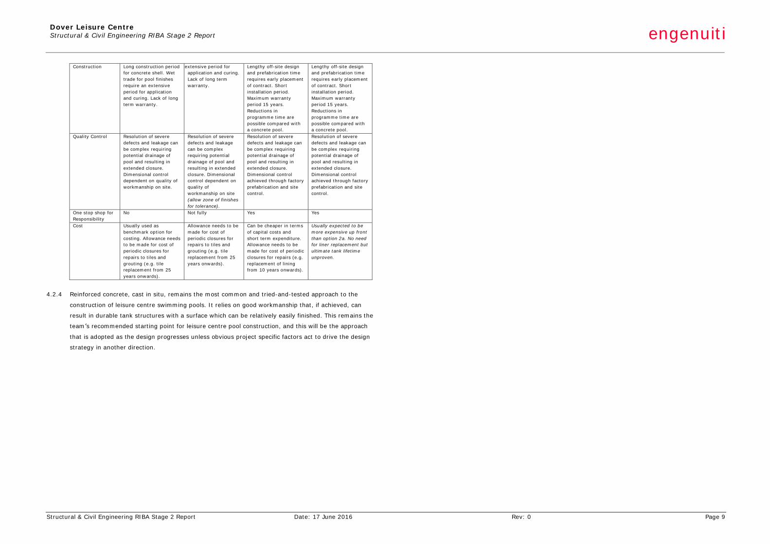
4.2.3 Options 1a, 1b, 2a, and 2b are compared in the following table. This table is derived from the ‘Pool Tank
Constructions’ table provided in Sport England; Swimming Pools Design Guidance Note; February
2011; revision 003. Additional comments which do not derive from this reference document are
provided in italics
1a. Reinforced
Concrete In-situ 1b. Sprayed Concrete 2a. Stainless Steel
Side Walls and PVC Liner
2b. Stainless Steel Walls and Floor with Welded Seams
Structural Monolithic design for whole of tank and pool surrounds when constructed from in-situ water retaining concrete to BS 8007 / BS EN 1992 Part 3 gives a highly stable structure.
Gunnite sprayed reinforced concrete. Usually with integrated transfer channel. Fixtures and fittings need to be integrated into the tank design. Particularly efficient method for pools with curved and irregularly shaped edges. Requires an experienced subcontractor.
Stainless steel side walls incorporating structural back framing fixed to a reinforced concrete floor.
Polished stainless steel side walls and floors incorporating structural back framing and welded seams. Stainless steel panels usually available up to depths not greater than 3m. Junction with pool surrounds and floor structure requires special care.
Waterproofing Inherent if pool well constructed and detailed in accordance with BS 8007 / BS EN 1992 Part 3. Can be augmented by waterproof liner and/or render.
Inherent if constructed correctly, and with the benefit that there are fewer joints (weak points) than is the case in a conventional cast in-situ walls.
Typically factory applied PVC facing to wall panels and loose PVC floor liner with seas thermally welded.
Inherent. Bare polished stainless steel wall and floor panels with welded joints.
Finishes Ceramic tiles on render backing recommended.
Ceramic tiles on render backing recommended.
PVC as described above. Can apply tile finishes on top.
No finish or ceramic tile options to upper wall sections subject to design and stiffening.
Robustness Robust – minimal risk of damage from vandalism or pool hall activities. Durable. Stable construction. Workmanship critical.
Robust – minimal risk of damage from vandalism or pool hall activities. Durable. Stable construction. Workmanship critical.
PVC lining is liable to mechanical damage from sharp objects e.g. puncture resulting in leakage. Potential movement issues at junctions with loose linings and more rigid surrounds. Workmanship critical.
Junctions between stainless steel tank and surround is obvious weak point. Workmanship critical.
Service Life Proven long service life. Examples c.100 years+.
Method only in common usage since 2000, so extent of lifetime not yet proven, but would expect long lifetime if workmanship adequate.
Periodic replacement of liners required (c.10 years). Oldest examples c.40 years.
Oldest examples c.40 years.
Maintenance Minimal long term maintenance of structure. Inspection and cleaning of grout anticipated on 5-7 year cycle. Re-grouting of ceramic tiles may be required at c.20 year intervals. Life of finishes will depend on quality of materials, maintenance of pool water quality, wave action and chemicals utilised.
Minimal long term maintenance of structure. Inspection and cleaning of grout anticipated on 5-7 year cycle. Re-grouting of ceramic tiles may be required at c.20 year intervals. Life of finishes will depend on quality of materials, maintenance of pool water quality, wave action and chemicals utilised.
Regular inspection and quick repair of PVC liner damage required. Annual inspection of stainless steel structure to check for pitting/corrosion.
Annual inspection of stainless steel structure to check for pitting/corrosion.
Dover Leisure Centre Structural & Civil Engineering RIBA Stage 2 Report engenuiti
Structural & Civil Engineering RIBA Stage 2 Report Date: 17 June 2016 Rev: 0 Page 9
Construction Long construction period for concrete shell. Wet trade for pool finishes require an extensive period for application and curing. Lack of long term warranty.
Wet trade for pool finishes require an extensive period for application and curing. Lack of long term warranty.
Lengthy off-site design and prefabrication time requires early placement of contract. Short installation period. Maximum warranty period 15 years. Reductions in programme time are possible compared with a concrete pool.
Lengthy off-site design and prefabrication time requires early placement of contract. Short installation period. Maximum warranty period 15 years. Reductions in programme time are possible compared with a concrete pool.
Quality Control Resolution of severe defects and leakage can be complex requiring potential drainage of pool and resulting in extended closure. Dimensional control dependent on quality of workmanship on site.
Resolution of severe defects and leakage can be complex requiring potential drainage of pool and resulting in extended closure. Dimensional control dependent on quality of workmanship on site (allow zone of finishes for tolerance).
Resolution of severe defects and leakage can be complex requiring potential drainage of pool and resulting in extended closure. Dimensional control achieved through factory prefabrication and site control.
Resolution of severe defects and leakage can be complex requiring potential drainage of pool and resulting in extended closure. Dimensional control achieved through factory prefabrication and site control.
One stop shop for Responsibility
No Not fully Yes Yes
Cost Usually used as benchmark option for costing. Allowance needs to be made for cost of periodic closures for repairs to tiles and grouting (e.g. tile replacement from 25 years onwards).
Allowance needs to be made for cost of periodic closures for repairs to tiles and grouting (e.g. tile replacement from 25 years onwards).
Can be cheaper in terms of capital costs and short term expenditure. Allowance needs to be made for cost of periodic closures for repairs (e.g. replacement of lining from 10 years onwards).
Usually expected to be more expensive up front than option 2a. No need for liner replacement but ultimate tank lifetime unproven.
4.2.4 Reinforced concrete, cast in situ, remains the most common and tried-and-tested approach to the
construction of leisure centre swimming pools. It relies on good workmanship that, if achieved, can
result in durable tank structures with a surface which can be relatively easily finished. This remains the
team’s recommended starting point for leisure centre pool construction, and this will be the approach
that is adopted as the design progresses unless obvious project specific factors act to drive the design
strategy in another direction.
Dover Leisure Centre Structural & Civil Engineering RIBA Stage 2 Report engenuiti
Structural & Civil Engineering RIBA Stage 2 Report Date: 17 June 2016 Rev: 0 Page 10
5 SITE CONDITIONS
5.1 Background
5.1.1 A preliminary desk- top study of the geology has been undertaken for the site based on historical and
current topographic maps and British Geological Society borehole records.
5.1.2 A detailed site investigation including boreholes, in situ and laboratory geotechnical testing and testing
for any potential ground contamination has not been undertaken at this stage.
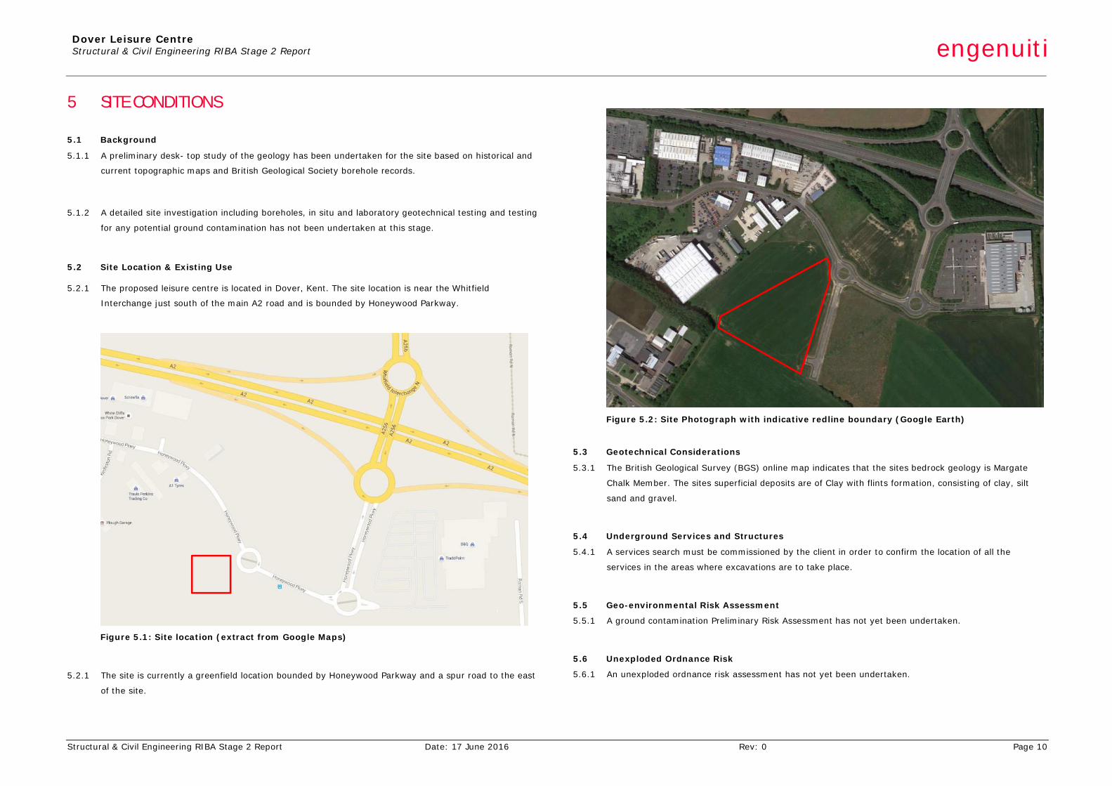
5.2 Site Location & Existing Use
5.2.1 The proposed leisure centre is located in Dover, Kent. The site location is near the Whitfield
Interchange just south of the main A2 road and is bounded by Honeywood Parkway.
Figure 5.1: Site location (extract from Google Maps)
5.2.1 The site is currently a greenfield location bounded by Honeywood Parkway and a spur road to the east
of the site.
Figure 5.2: Site Photograph with indicative redline boundary (Google Earth)
5.3 Geotechnical Considerations
5.3.1 The British Geological Survey (BGS) online map indicates that the sites bedrock geology is Margate
Chalk Member. The sites superficial deposits are of Clay with flints formation, consisting of clay, silt
sand and gravel.
5.4 Underground Services and Structures
5.4.1 A services search must be commissioned by the client in order to confirm the location of all the
services in the areas where excavations are to take place.
5.5 Geo-environmental Risk Assessment
5.5.1 A ground contamination Preliminary Risk Assessment has not yet been undertaken.
5.6 Unexploded Ordnance Risk
5.6.1 An unexploded ordnance risk assessment has not yet been undertaken.
Dover Leisure Centre Structural & Civil Engineering RIBA Stage 2 Report engenuiti
Structural & Civil Engineering RIBA Stage 2 Report Date: 17 June 2016 Rev: 0 Page 11
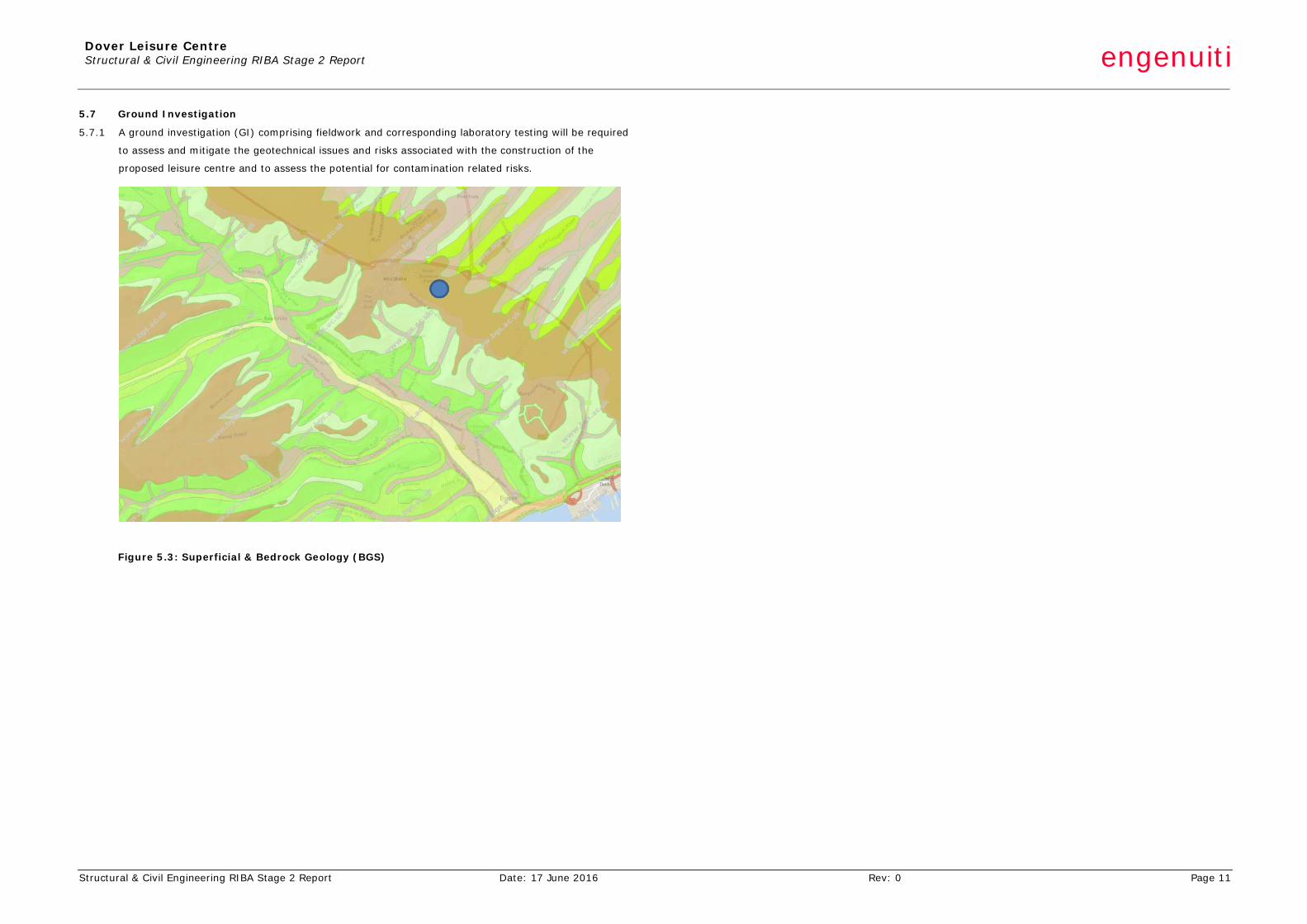
5.7 Ground Investigation
5.7.1 A ground investigation (GI) comprising fieldwork and corresponding laboratory testing will be required
to assess and mitigate the geotechnical issues and risks associated with the construction of the
proposed leisure centre and to assess the potential for contamination related risks.
Figure 5.3: Superficial & Bedrock Geology (BGS)
Dover Leisure Centre Structural & Civil Engineering RIBA Stage 2 Report engenuiti
Structural & Civil Engineering RIBA Stage 2 Report Date: 17 June 2016 Rev: 0 Page 12
6 SUBSTRUCTURE & FOUNDATIONS
6.1 Foundation Solutions
6.1.1 Based on the desktop study of the local geology and borehole data available on the BGS website we
suggest that the foundation solution may be suitable for shallow pads and ground bearing slabs
founded on the chalk.
6.1.2 Our experience of leisure centre construction suggests that shallow foundations and ground bearing
pool structure are the most favoured starting point for foundation solutions from a cost perspective.
From a cost perspective, allowance should be made for a piled foundation solution until further ground
information is available.
6.2 RC Ground Bearing Slabs, Edge Beams & Upstands
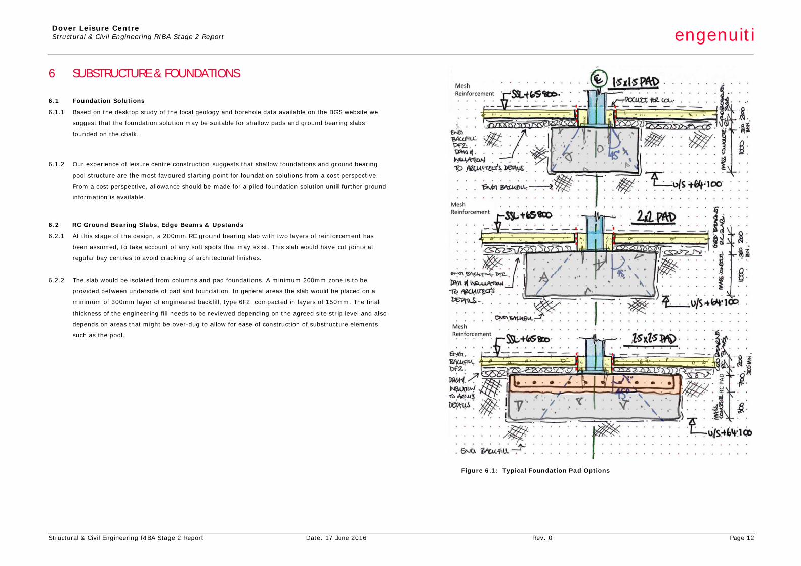
6.2.1 At this stage of the design, a 200mm RC ground bearing slab with two layers of reinforcement has
been assumed, to take account of any soft spots that may exist. This slab would have cut joints at
regular bay centres to avoid cracking of architectural finishes.
6.2.2 The slab would be isolated from columns and pad foundations. A minimum 200mm zone is to be
provided between underside of pad and foundation. In general areas the slab would be placed on a
minimum of 300mm layer of engineered backfill, type 6F2, compacted in layers of 150mm. The final
thickness of the engineering fill needs to be reviewed depending on the agreed site strip level and also
depends on areas that might be over-dug to allow for ease of construction of substructure elements
such as the pool.
Figure 6.1: Typical Foundation Pad Options
Dover Leisure Centre Structural & Civil Engineering RIBA Stage 2 Report engenuiti
Structural & Civil Engineering RIBA Stage 2 Report Date: 17 June 2016 Rev: 0 Page 13
6.2.3 The architectural finishes will determine the founding level of the slab. These typically range from
15mm for a skimming screed up to 300mm in changing areas. Where the slab changes level a 300mm
RC thickening is to be provided. The final level of slabs will be coordinated at design Stage 4a.
6.2.4 The perimeter of the building has an in-situ ground beam that incorporates a step for masonry
support. This spans between pad foundations is tied into the ground bearing slab. This edge beam can
also be constructed in precast concrete if required for programme reasons.
6.2.5 The swimming pool area and changing village will require RC upstands and bunds to separate different
areas. At this stage of the project typical details are provided by the Architect and should be allowed
for in the cost plan.
6.3 Swimming Pool RC Walls and Slabs
6.3.1 We suggest that subject to ground conditions the swimming pool walls and base slab are to be built as
in-situ reinforced concrete with a tiled finish.
6.3.2 The in-situ reinforced concrete option has been suggested at this design stage on the basis that it is a
tried-and-tested method, with good availability of ground workers who can complete the works. Crack
control will be managed through reinforcement scheduling. It should be noted that the concrete
specification will have higher workmanship tolerances to ensure that the clear distances are achieved.
These RC boxes will be designed to limited crack widths to provide water tightness without the need
for any additives, however options for additives can be considered if thought to be advantageous from
a programme perspective.
6.3.3 The swimming pool reinforced concrete walls generally vary from approximately 1.0m to 2.5m depth.
The walls are typically 300mm thick and local areas will be thickened to 450mm to allow for scum
channels to be incorporated in the wall. A horizontal movement joint is to be provided between the
pool walls and ground bearing slab.
6.3.4 The base of the swimming pool is to be a 300-400mm thick reinforced concrete ground bearing slab.
This thickness is required to enable reinforcement to lap from the wall into the base to resist bending
from backfill placed behind the wall. The base slab will also be subject to hydrostatic pressures from
the water table. As the pool depth is to be approximately 2.5m in the deepest location it is anticipated
that by providing a 300-400mm base thickness will be approximately equal to the hydrostatic uplift
forces.
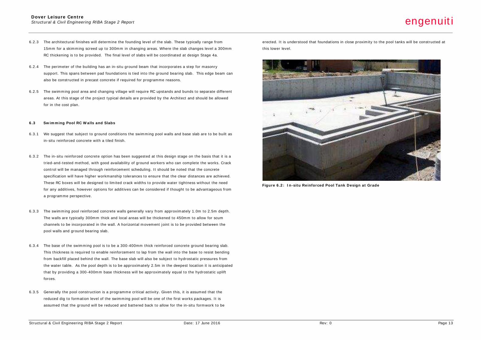
6.3.5 Generally the pool construction is a programme critical activity. Given this, it is assumed that the
reduced dig to formation level of the swimming pool will be one of the first works packages. It is
assumed that the ground will be reduced and battered back to allow for the in-situ formwork to be
erected. It is understood that foundations in close proximity to the pool tanks will be constructed at
this lower level.
Figure 6.2: In-situ Reinforced Pool Tank Design at Grade
Dover Leisure Centre Structural & Civil Engineering RIBA Stage 2 Report engenuiti
Structural & Civil Engineering RIBA Stage 2 Report Date: 17 June 2016 Rev: 0 Page 14
7 SUPERSTRUCTURE
7.1 Structural Framing
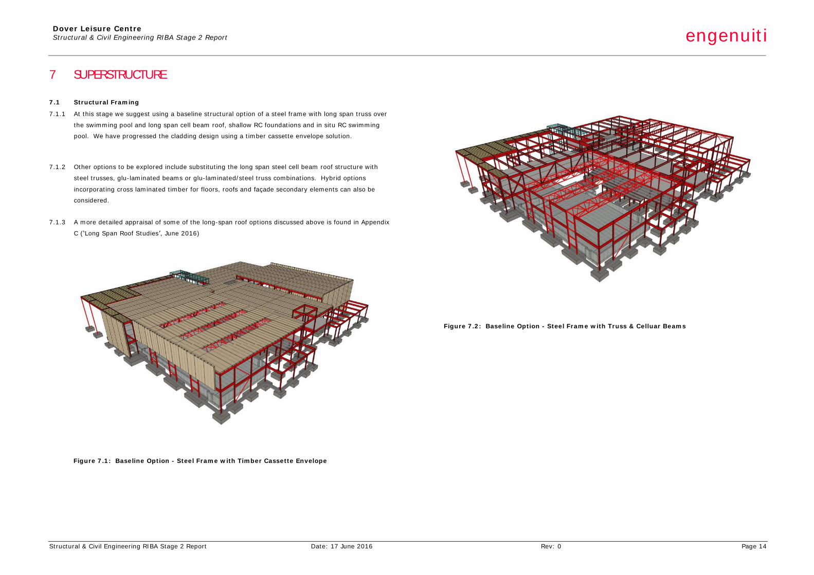
7.1.1 At this stage we suggest using a baseline structural option of a steel frame with long span truss over
the swimming pool and long span cell beam roof, shallow RC foundations and in situ RC swimming
pool. We have progressed the cladding design using a timber cassette envelope solution.
7.1.2 Other options to be explored include substituting the long span steel cell beam roof structure with
steel trusses, glu-laminated beams or glu-laminated/steel truss combinations. Hybrid options
incorporating cross laminated timber for floors, roofs and façade secondary elements can also be
considered.
7.1.3 A more detailed appraisal of some of the long-span roof options discussed above is found in Appendix
C (‘Long Span Roof Studies’, June 2016)
Figure 7.1: Baseline Option - Steel Frame with Timber Cassette Envelope
Figure 7.2: Baseline Option - Steel Frame with Truss & Celluar Beams
Dover Leisure Centre Structural & Civil Engineering RIBA Stage 2 Report engenuiti
Structural & Civil Engineering RIBA Stage 2 Report Date: 17 June 2016 Rev: 0 Page 15
8 BUILDING ENVELOPE
8.1 Overview
8.1.1 The building envelope is a key structural component in all buildings. The coordination of external and
internal skins provides an efficient building envelope solution and there are several structural
components to the envelope.
8.1.2 The building envelope for leisure centres generally comprises of the following components:
• Roof Options – Timber cassette, Cross laminated Timber (CLT), and light weight steel and
aluminium decking.
• Sports Hall & Swimming Pool high level cladding - Lightweight cladding panels (Kingspan) with
secondary steel cold form backing system, timber cassettes
• Open elevations – glazed curtain walling with secondary steel cold form fixings as required.
• Sports Hall & Swimming Pool low level cladding – concrete block / brick masonry cavity system or
other cladding material. Blockwork for solid wall construction.
• It should be noted CLT panels can also be used for wall elevations in lieu of blockwork and
secondary steel systems.
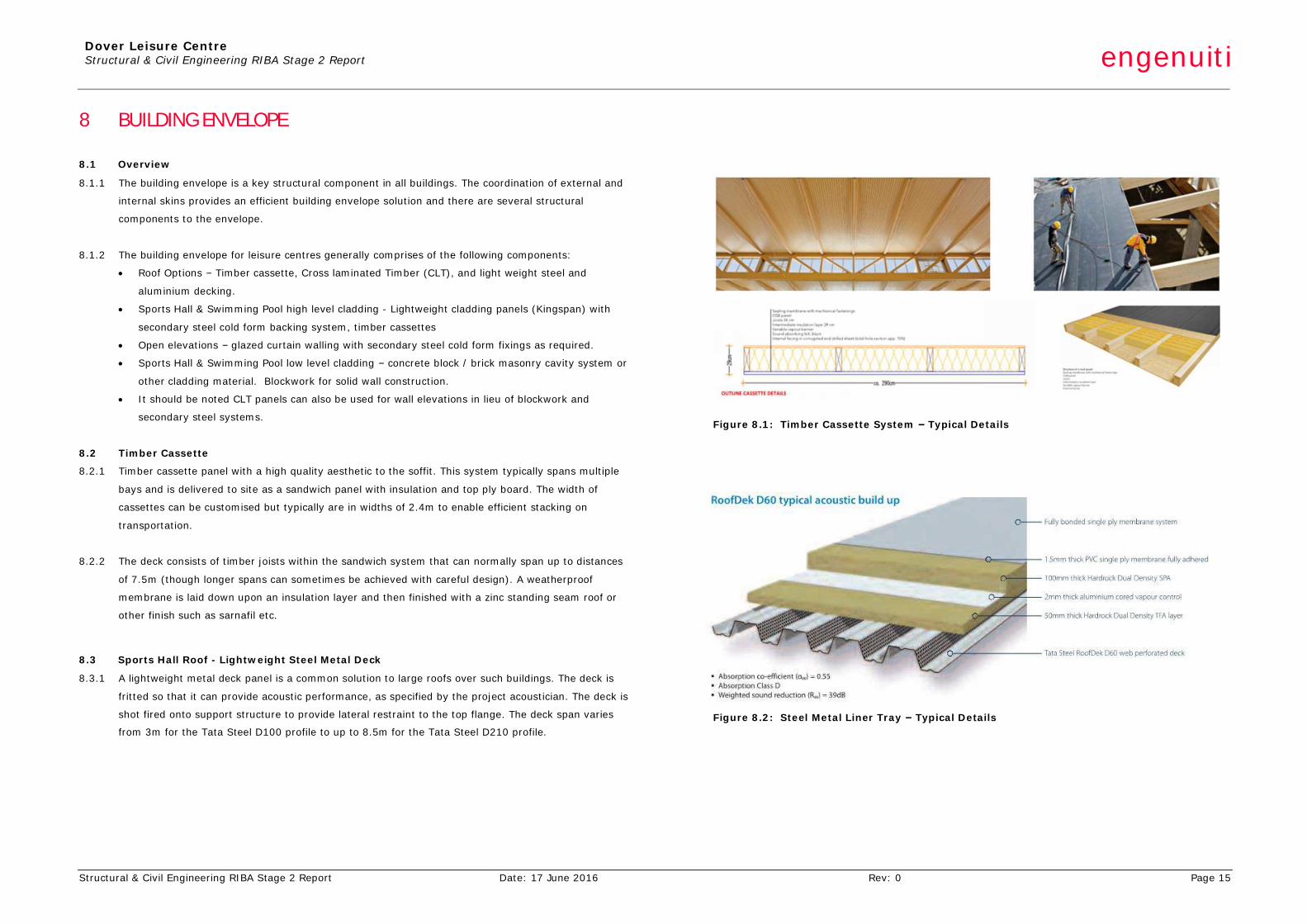
8.2 Timber Cassette
8.2.1 Timber cassette panel with a high quality aesthetic to the soffit. This system typically spans multiple
bays and is delivered to site as a sandwich panel with insulation and top ply board. The width of
cassettes can be customised but typically are in widths of 2.4m to enable efficient stacking on
transportation.
8.2.2 The deck consists of timber joists within the sandwich system that can normally span up to distances
of 7.5m (though longer spans can sometimes be achieved with careful design). A weatherproof
membrane is laid down upon an insulation layer and then finished with a zinc standing seam roof or
other finish such as sarnafil etc.
8.3 Sports Hall Roof - Lightweight Steel Metal Deck
8.3.1 A lightweight metal deck panel is a common solution to large roofs over such buildings. The deck is
fritted so that it can provide acoustic performance, as specified by the project acoustician. The deck is
shot fired onto support structure to provide lateral restraint to the top flange. The deck span varies
from 3m for the Tata Steel D100 profile to up to 8.5m for the Tata Steel D210 profile.
Figure 8.1: Timber Cassette System – Typical Details
Insulation and waterproof membrane are provided over the metal deck above the central zone, wh
architectural build up to the roofs is to be confirmed by the Architect.
Figure 8.2: Steel Metal Liner Tray – Typical Details
Dover Leisure Centre Structural & Civil Engineering RIBA Stage 2 Report engenuiti
Structural & Civil Engineering RIBA Stage 2 Report Date: 17 June 2016 Rev: 0 Page 16
8.4 Lightweight Cladding Panels
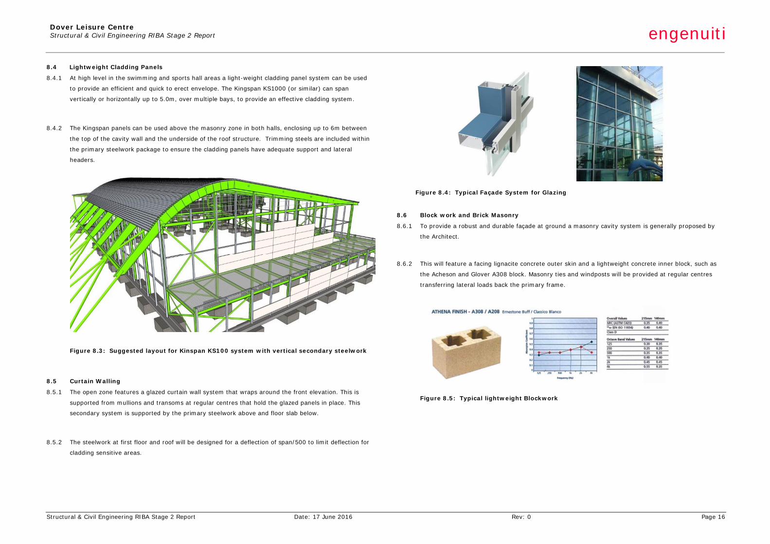
8.4.1 At high level in the swimming and sports hall areas a light-weight cladding panel system can be used
to provide an efficient and quick to erect envelope. The Kingspan KS1000 (or similar) can span
vertically or horizontally up to 5.0m, over multiple bays, to provide an effective cladding system.
8.4.2 The Kingspan panels can be used above the masonry zone in both halls, enclosing up to 6m between
the top of the cavity wall and the underside of the roof structure. Trimming steels are included within
the primary steelwork package to ensure the cladding panels have adequate support and lateral
headers.
Figure 8.3: Suggested layout for Kinspan KS100 system with vertical secondary steelwork
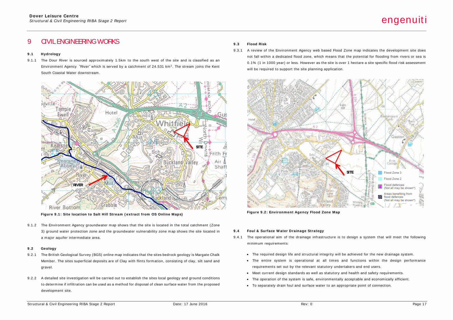
8.5 Curtain Walling
8.5.1 The open zone features a glazed curtain wall system that wraps around the front elevation. This is
supported from mullions and transoms at regular centres that hold the glazed panels in place. This
secondary system is supported by the primary steelwork above and floor slab below.
8.5.2 The steelwork at first floor and roof will be designed for a deflection of span/500 to limit deflection for
cladding sensitive areas.
Figure 8.4: Typical Façade System for Glazing
8.6 Block work and Brick Masonry
8.6.1 To provide a robust and durable façade at ground a masonry cavity system is generally proposed by
the Architect.
8.6.2 This will feature a facing lignacite concrete outer skin and a lightweight concrete inner block, such as
the Acheson and Glover A308 block. Masonry ties and windposts will be provided at regular centres
transferring lateral loads back the primary frame.
Figure 8.5: Typical lightweight Blockwork
Dover Leisure Centre Structural & Civil Engineering RIBA Stage 2 Report engenuiti
Structural & Civil Engineering RIBA Stage 2 Report Date: 17 June 2016 Rev: 0 Page 17
9 CIVIL ENGINEERING WORKS
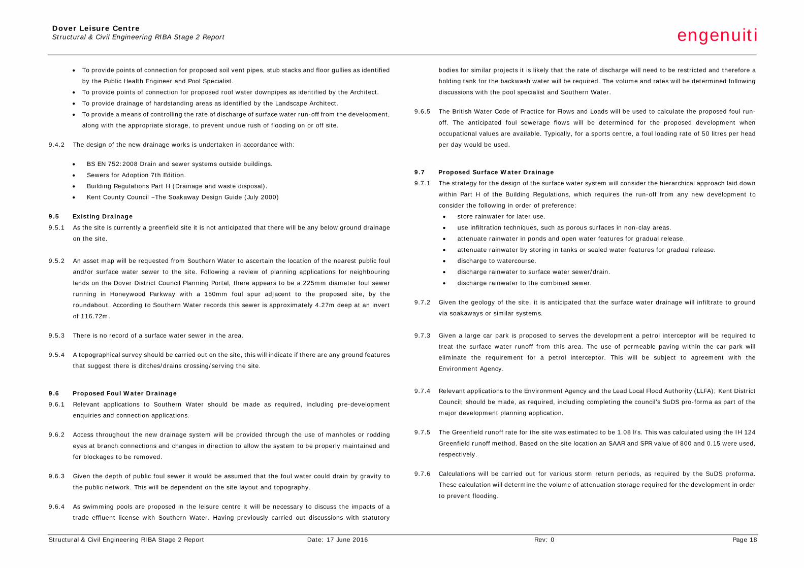
9.1 Hydrology
9.1.1 The Dour River is sourced approximately 1.5km to the south west of the site and is classified as an
Environment Agency ‘River’ which is served by a catchment of 24.531 km2. The stream joins the Kent
South Coastal Water downstream.
Figure 9.1: Site location to Salt Hill Stream (extract from OS Online Maps)
9.1.2 The Environment Agency groundwater map shows that the site is located in the total catchment (Zone
3) ground water protection zone and the groundwater vulnerability zone map shows the site located in
a major aquifer intermediate area.
9.2 Geology
9.2.1 The British Geological Survey (BGS) online map indicates that the sites bedrock geology is Margate Chalk
Member. The sites superficial deposits are of Clay with flints formation, consisting of clay, silt sand and
gravel.
9.2.2 A detailed site investigation will be carried out to establish the sites local geology and ground conditions
to determine if infiltration can be used as a method for disposal of clean surface water from the proposed
development site.
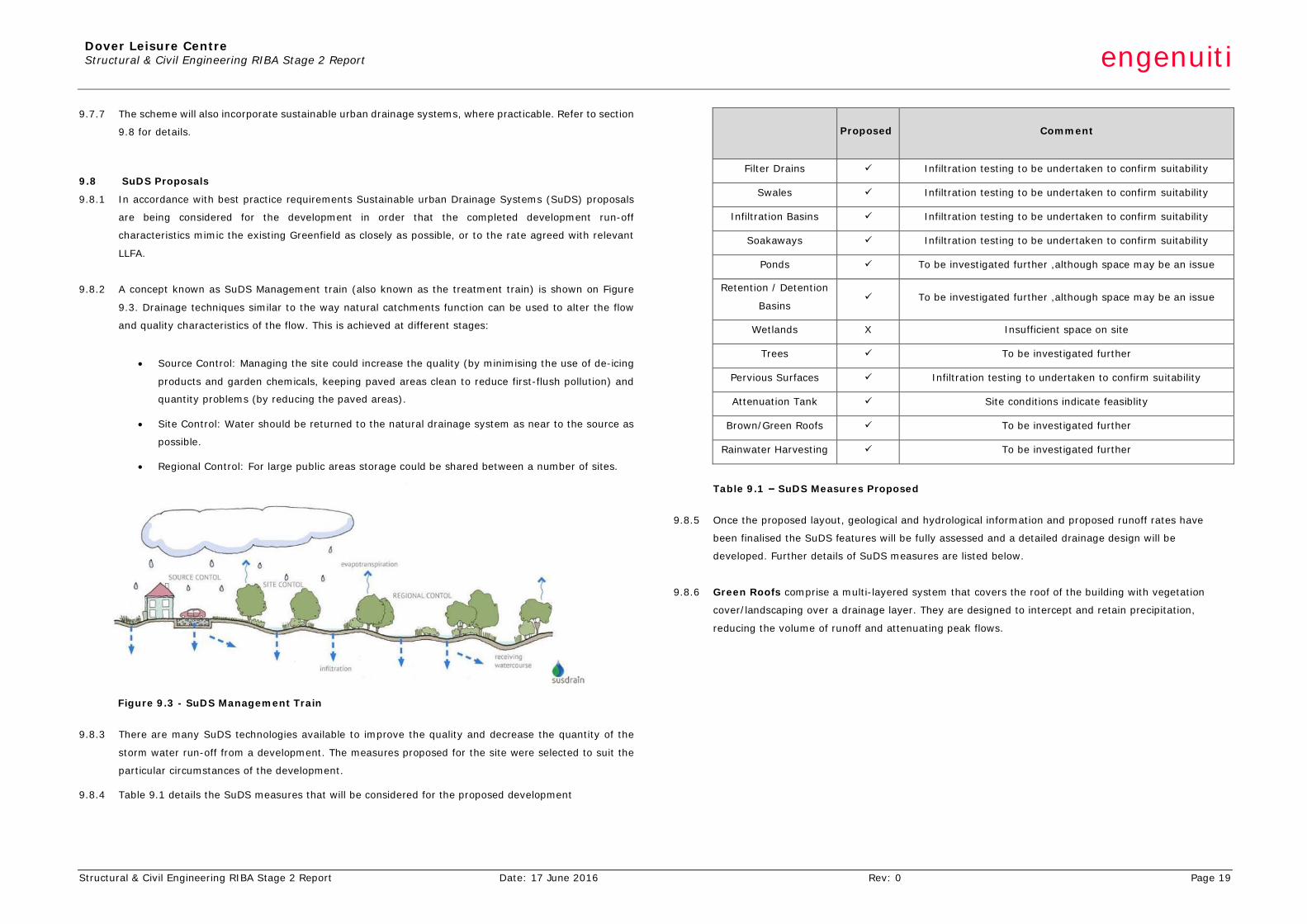
9.3 Flood Risk
9.3.1 A review of the Environment Agency web based Flood Zone map indicates the development site does
not fall within a dedicated flood zone, which means that the potential for flooding from rivers or sea is
0.1% (1 in 1000 year) or less. However as the site is over 1 hectare a site specific flood risk assessment
will be required to support the site planning application.
Figure 9.2: Environment Agency Flood Zone Map
9.4 Foul & Surface Water Drainage Strategy
9.4.1 The operational aim of the drainage infrastructure is to design a system that will meet the following
minimum requirements:
• The required design life and structural integrity will be achieved for the new drainage system.
• The entire system is operational at all times and functions within the design performance
requirements set out by the relevant statutory undertakers and end users.
• Meet current design standards as well as statutory and health and safety requirements.
• The operation of the system is safe, environmentally acceptable and economically efficient.
• To separately drain foul and surface water to an appropriate point of connection.
SITE
SITE
RIVER
Dover Leisure Centre Structural & Civil Engineering RIBA Stage 2 Report engenuiti
Structural & Civil Engineering RIBA Stage 2 Report Date: 17 June 2016 Rev: 0 Page 18
• To provide points of connection for proposed soil vent pipes, stub stacks and floor gullies as identified
by the Public Health Engineer and Pool Specialist.
• To provide points of connection for proposed roof water downpipes as identified by the Architect.
• To provide drainage of hardstanding areas as identified by the Landscape Architect.
• To provide a means of controlling the rate of discharge of surface water run-off from the development,
along with the appropriate storage, to prevent undue rush of flooding on or off site.
9.4.2 The design of the new drainage works is undertaken in accordance with:
• BS EN 752:2008 Drain and sewer systems outside buildings.
• Sewers for Adoption 7th Edition.
• Building Regulations Part H (Drainage and waste disposal).
• Kent County Council –The Soakaway Design Guide (July 2000)
9.5 Existing Drainage
9.5.1 As the site is currently a greenfield site it is not anticipated that there will be any below ground drainage
on the site.
9.5.2 An asset map will be requested from Southern Water to ascertain the location of the nearest public foul
and/or surface water sewer to the site. Following a review of planning applications for neighbouring
lands on the Dover District Council Planning Portal, there appears to be a 225mm diameter foul sewer
running in Honeywood Parkway with a 150mm foul spur adjacent to the proposed site, by the
roundabout. According to Southern Water records this sewer is approximately 4.27m deep at an invert
of 116.72m.
9.5.3 There is no record of a surface water sewer in the area.
9.5.4 A topographical survey should be carried out on the site, this will indicate if there are any ground features
that suggest there is ditches/drains crossing/serving the site.
9.6 Proposed Foul Water Drainage
9.6.1 Relevant applications to Southern Water should be made as required, including pre-development
enquiries and connection applications.
9.6.2 Access throughout the new drainage system will be provided through the use of manholes or rodding
eyes at branch connections and changes in direction to allow the system to be properly maintained and
for blockages to be removed.
9.6.3 Given the depth of public foul sewer it would be assumed that the foul water could drain by gravity to
the public network. This will be dependent on the site layout and topography.
9.6.4 As swimming pools are proposed in the leisure centre it will be necessary to discuss the impacts of a
trade effluent license with Southern Water. Having previously carried out discussions with statutory
bodies for similar projects it is likely that the rate of discharge will need to be restricted and therefore a
holding tank for the backwash water will be required. The volume and rates will be determined following
discussions with the pool specialist and Southern Water.
9.6.5 The British Water Code of Practice for Flows and Loads will be used to calculate the proposed foul run-
off. The anticipated foul sewerage flows will be determined for the proposed development when
occupational values are available. Typically, for a sports centre, a foul loading rate of 50 litres per head
per day would be used.
9.7 Proposed Surface Water Drainage
9.7.1 The strategy for the design of the surface water system will consider the hierarchical approach laid down
within Part H of the Building Regulations, which requires the run-off from any new development to
consider the following in order of preference:
• store rainwater for later use.
• use infiltration techniques, such as porous surfaces in non-clay areas.
• attenuate rainwater in ponds and open water features for gradual release.
• attenuate rainwater by storing in tanks or sealed water features for gradual release.
• discharge to watercourse.
• discharge rainwater to surface water sewer/drain.
• discharge rainwater to the combined sewer.
9.7.2 Given the geology of the site, it is anticipated that the surface water drainage will infiltrate to ground
via soakaways or similar systems.
9.7.3 Given a large car park is proposed to serves the development a petrol interceptor will be required to
treat the surface water runoff from this area. The use of permeable paving within the car park will
eliminate the requirement for a petrol interceptor. This will be subject to agreement with the
Environment Agency.
9.7.4 Relevant applications to the Environment Agency and the Lead Local Flood Authority (LLFA); Kent District
Council; should be made, as required, including completing the council’s SuDS pro-forma as part of the
major development planning application.
9.7.5 The Greenfield runoff rate for the site was estimated to be 1.08 l/s. This was calculated using the IH 124
Greenfield runoff method. Based on the site location an SAAR and SPR value of 800 and 0.15 were used,
respectively.
9.7.6 Calculations will be carried out for various storm return periods, as required by the SuDS proforma.
These calculation will determine the volume of attenuation storage required for the development in order
to prevent flooding.
Dover Leisure Centre Structural & Civil Engineering RIBA Stage 2 Report engenuiti
Structural & Civil Engineering RIBA Stage 2 Report Date: 17 June 2016 Rev: 0 Page 19
9.7.7 The scheme will also incorporate sustainable urban drainage systems, where practicable. Refer to section
9.8 for details.
9.8 SuDS Proposals
9.8.1 In accordance with best practice requirements Sustainable urban Drainage Systems (SuDS) proposals
are being considered for the development in order that the completed development run-off
characteristics mimic the existing Greenfield as closely as possible, or to the rate agreed with relevant
LLFA.
9.8.2 A concept known as SuDS Management train (also known as the treatment train) is shown on Figure
9.3. Drainage techniques similar to the way natural catchments function can be used to alter the flow
and quality characteristics of the flow. This is achieved at different stages:
• Source Control: Managing the site could increase the quality (by minimising the use of de-icing
products and garden chemicals, keeping paved areas clean to reduce first-flush pollution) and
quantity problems (by reducing the paved areas).
• Site Control: Water should be returned to the natural drainage system as near to the source as
possible.
• Regional Control: For large public areas storage could be shared between a number of sites.
Figure 9.3 - SuDS Management Train
9.8.3 There are many SuDS technologies available to improve the quality and decrease the quantity of the
storm water run-off from a development. The measures proposed for the site were selected to suit the
particular circumstances of the development.
9.8.4 Table 9.1 details the SuDS measures that will be considered for the proposed development
Proposed Comment
Filter Drains ü Infiltration testing to be undertaken to confirm suitability
Swales ü Infiltration testing to be undertaken to confirm suitability
Infiltration Basins ü Infiltration testing to be undertaken to confirm suitability
Soakaways ü Infiltration testing to be undertaken to confirm suitability
Ponds ü To be investigated further ,although space may be an issue
Retention / Detention
Basins ü To be investigated further ,although space may be an issue
Wetlands X Insufficient space on site
Trees ü To be investigated further
Pervious Surfaces ü Infiltration testing to undertaken to confirm suitability
Attenuation Tank ü Site conditions indicate feasiblity
Brown/Green Roofs ü To be investigated further
Rainwater Harvesting ü To be investigated further
Table 9.1 – SuDS Measures Proposed
9.8.5 Once the proposed layout, geological and hydrological information and proposed runoff rates have
been finalised the SuDS features will be fully assessed and a detailed drainage design will be
developed. Further details of SuDS measures are listed below.
9.8.6 Green Roofs comprise a multi-layered system that covers the roof of the building with vegetation
cover/landscaping over a drainage layer. They are designed to intercept and retain precipitation,
reducing the volume of runoff and attenuating peak flows.
Dover Leisure Centre Structural & Civil Engineering RIBA Stage 2 Report engenuiti
Structural & Civil Engineering RIBA Stage 2 Report Date: 17 June 2016 Rev: 0 Page 20
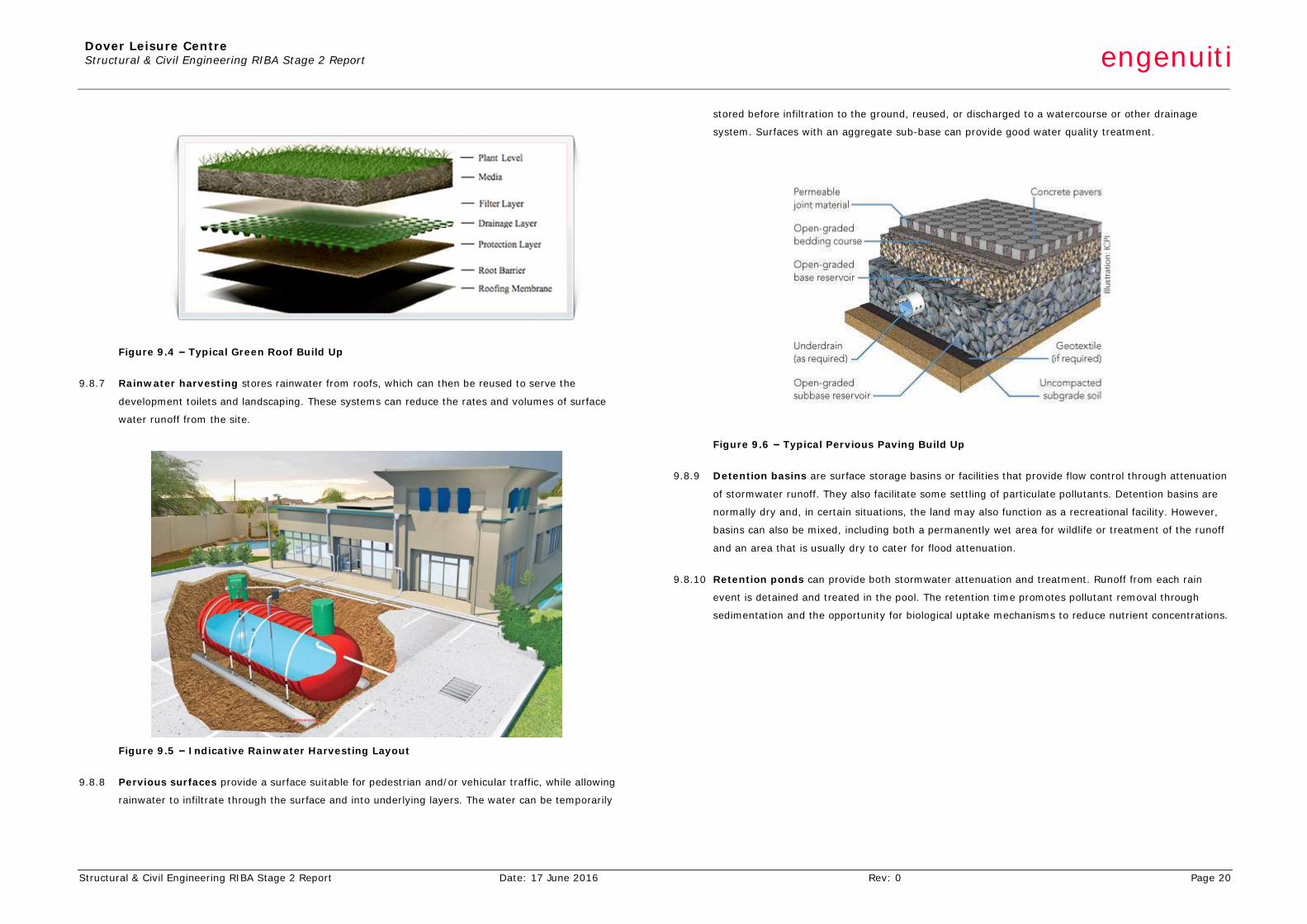
Figure 9.4 – Typical Green Roof Build Up
9.8.7 Rainwater harvesting stores rainwater from roofs, which can then be reused to serve the
development toilets and landscaping. These systems can reduce the rates and volumes of surface
water runoff from the site.
Figure 9.5 – Indicative Rainwater Harvesting Layout
9.8.8 Pervious surfaces provide a surface suitable for pedestrian and/or vehicular traffic, while allowing
rainwater to infiltrate through the surface and into underlying layers. The water can be temporarily
stored before infiltration to the ground, reused, or discharged to a watercourse or other drainage
system. Surfaces with an aggregate sub-base can provide good water quality treatment.
Figure 9.6 – Typical Pervious Paving Build Up
9.8.9 Detention basins are surface storage basins or facilities that provide flow control through attenuation
of stormwater runoff. They also facilitate some settling of particulate pollutants. Detention basins are
normally dry and, in certain situations, the land may also function as a recreational facility. However,
basins can also be mixed, including both a permanently wet area for wildlife or treatment of the runoff
and an area that is usually dry to cater for flood attenuation.
9.8.10 Retention ponds can provide both stormwater attenuation and treatment. Runoff from each rain
event is detained and treated in the pool. The retention time promotes pollutant removal through
sedimentation and the opportunity for biological uptake mechanisms to reduce nutrient concentrations.
Dover Leisure Centre Structural & Civil Engineering RIBA Stage 2 Report engenuiti
Structural & Civil Engineering RIBA Stage 2 Report Date: 17 June 2016 Rev: 0 Page 21
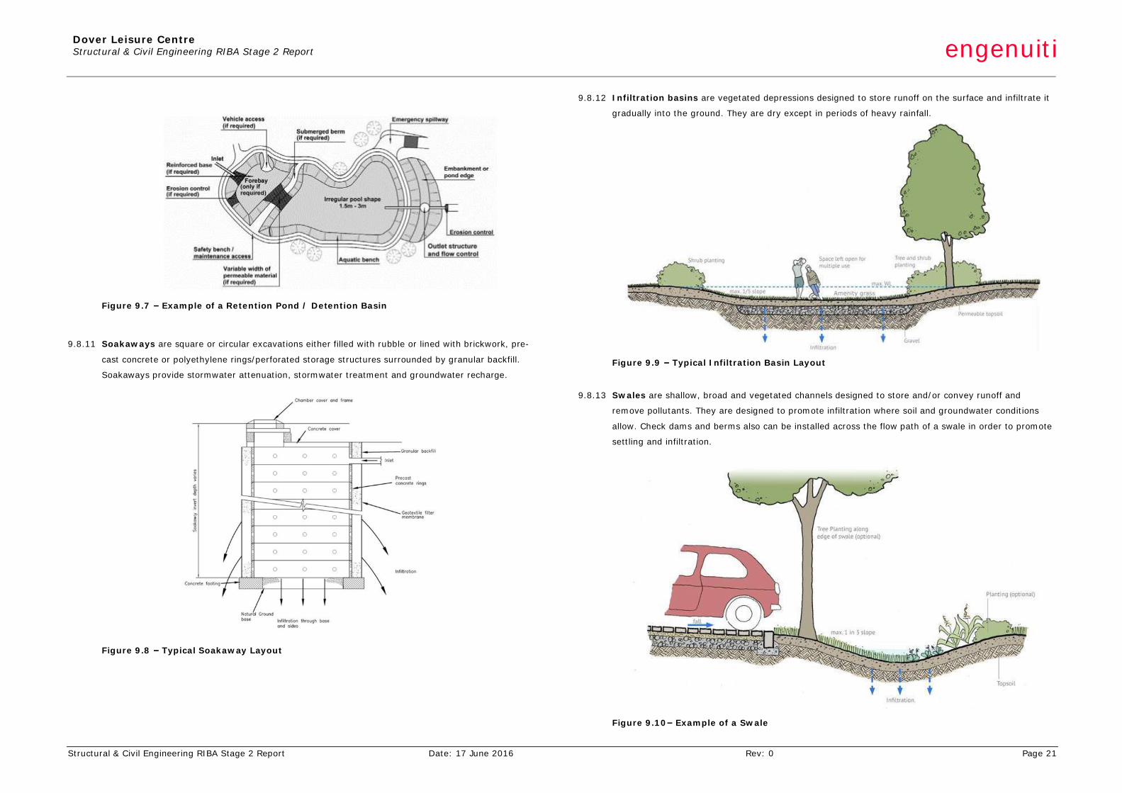
Figure 9.7 – Example of a Retention Pond / Detention Basin
9.8.11 Soakaways are square or circular excavations either filled with rubble or lined with brickwork, pre-
cast concrete or polyethylene rings/perforated storage structures surrounded by granular backfill.
Soakaways provide stormwater attenuation, stormwater treatment and groundwater recharge.
Figure 9.8 – Typical Soakaway Layout
9.8.12 Infiltration basins are vegetated depressions designed to store runoff on the surface and infiltrate it
gradually into the ground. They are dry except in periods of heavy rainfall.
Figure 9.9 – Typical Infiltration Basin Layout
9.8.13 Swales are shallow, broad and vegetated channels designed to store and/or convey runoff and
remove pollutants. They are designed to promote infiltration where soil and groundwater conditions
allow. Check dams and berms also can be installed across the flow path of a swale in order to promote
settling and infiltration.
Figure 9.10– Example of a Swale
Dover Leisure Centre Structural & Civil Engineering RIBA Stage 2 Report engenuiti
Structural & Civil Engineering RIBA Stage 2 Report Date: 17 June 2016 Rev: 0 Page 22
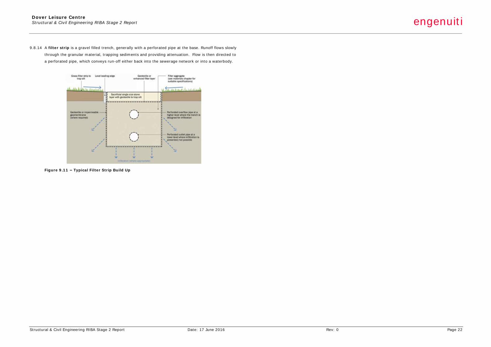
9.8.14 A filter strip is a gravel filled trench, generally with a perforated pipe at the base. Runoff flows slowly
through the granular material, trapping sediments and providing attenuation. Flow is then directed to
a perforated pipe, which conveys run-off either back into the sewerage network or into a waterbody.
Figure 9.11 – Typical Filter Strip Build Up
Dover Leisure Centre Structural & Civil Engineering RIBA Stage 2 Report engenuiti
Structural & Civil Engineering RIBA Stage 2 Report Date: 17 June 2016 Rev: 0 Page 23
10 SUSTAINABILITY 10.1 General
10.1.1 Sustainability is a key feature in the design processes that Engenuiti undertakes. As an industry we
use a significant amount of the Earth’s natural resources and by default this means we can
significantly reduce our resource and energy demands in the projects we design.
10.1.2 For this project a number of sustainability considerations have been included in the design and a
number more should be considered in the future. In particular the use of solid timber in lieu of
structural steel and either block work or cold formed steel secondary backing systems should be
explored.
10.1.3 Concrete will be proposed in which the cement content could be reduced by using cement
replacements such as pulverised fuel ash or ground granulated blast furnace slag to form a more
sustainable mix. The decision to use concrete has been based on sound engineering principles and
hence reducing the impact of using a large quantity is the most sustainable option. Where exposed
concrete is to be used, careful selection of additives should be made to ensure that colour consistency
is not degraded to the point where the finish is left unacceptable and requires painting.
10.2 Concrete
10.2.1 The global cement industry accounts for around 5% of global CO2 emissions (source: World Business
Council for Sustainable Development). The construction and demolition of buildings accounts for
around 120 million tonnes of waste material in the UK, about half the national total waste.
10.2.2 There are significant opportunities for concrete construction to reduce its environmental impact
through the specification and construction processes.
10.3 Conservation of Natural Resources
10.3.1 Although global supplies of the raw materials used to make cement, and aggregates used in concrete
are not in short supply, their extraction can cause damage to their local environment. It is generally
more sustainable to make use of a waste product in lieu of extracting more raw material: it has the
double benefit of conserving natural resources for use by future generations and reducing the problem
of disposal of unwanted materials.
10.3.2 Cement replacements – GGBS and PFA cannot replace 100% of the OPC used in cement as they rely
on the hydration products from the lime to ‘kick start’ their own hydration reactions. However, 30 -
50% replacement is very common and will have limited effects on the concrete. Replacement rates of
80% are possible in certain circumstances. This has the potential to save a large amount of reserves
of lime and clay, the raw materials used to make OPC.
10.3.3 Recycled aggregates – as the material that makes up the largest proportion of concrete by mass, the
use of recycled coarse aggregates have a significant effect on reducing the mass of raw material used
to make cement. The use of recycled fine aggregates is also possible and beneficial for similar
regions.
10.3.4 Water – concrete manufacturers with a well developed environmental management systems should
be recycling much of their water, as a great deal can be wasted in batching plants, through washing
out machinery and lorries. Simple procedures minimise the use of water, with obvious benefits,
especially in dry climates where it is a resource in short supply.
10.3.5 Formwork – by increasing the number of times formwork panels can be reused, the volume of
material required on a project will be greatly reduced.
10.3.6 Release agents – there are many different types of release agents for use on formwork systems,
made from different raw materials. Those that are derived from vegetable oil or other biodegradable
sources, rather than petroleum based materials are preferable from a sustainability point of view, as
they are made from readily renewable materials. They may cost more per litre, but the coverage
rate of the petroleum based versions should be checked: often they require more coats, so the cost
per m2 of formwork is similar and the labour cost may be more.
10.4 Embodied Energy and Embodied CO2
10.4.1 Although the cement industry has been making significant steps to improve efficiency and so reduce
its CO2 emissions, it will always be a major emitter as the chemical reaction involved in the
manufacture of OPC produces CO2 as a waste product. The drive to reduce the carbon footprint of
industrial processes has resulted in significant interest in using cement replacement materials in
concrete to reduce its carbon footprint.
10.4.2 Measuring the embodied CO2 of raw materials is not a simple process, and depends very much on the
boundary conditions and methodologies that are applied.
10.4.3 However, Table 10.1 shows data that can be used to make ‘order of magnitude’ comparisons. WRAP
(Waste Reduction Action Programme) is private company in the UK which works in partnership with
organisations to reduce waste and increase recycling.
Dover Leisure Centre Structural & Civil Engineering RIBA Stage 2 Report engenuiti
Structural & Civil Engineering RIBA Stage 2 Report Date: 17 June 2016 Rev: 0 Page 24
Embodied Energy
MJ / tonne
Embodied CO2
Kg CO2 / tonne
OPC 4770 800
GGBS 436 100
PFA 12 1
Table 10.1 - Embodied energy and CO2 data (WRAP carbon calculator)
10.4.4 It can be seen that significant savings can be made by replacing OPC with replacements. An early
estimate of the volume of concrete to be used in the project is around 9500m3. Assuming a typical
mix that contains around 16% of cementitious materials by mass, and the use of a blended cement of
50% OPC, 50% replacement material, the CO2 saving on the project will be approximately 1000
tonnes or 1500 tonnes, depending on whether GGBS or PFA are used.
10.4.5 It is not thought that the use of recycled aggregates offers a saving in embodied energy or CO2 due to
the significant processing that it must undergo in order to be used in most circumstances (transport
from its original location, crushing if necessary, washing, grading etc.).
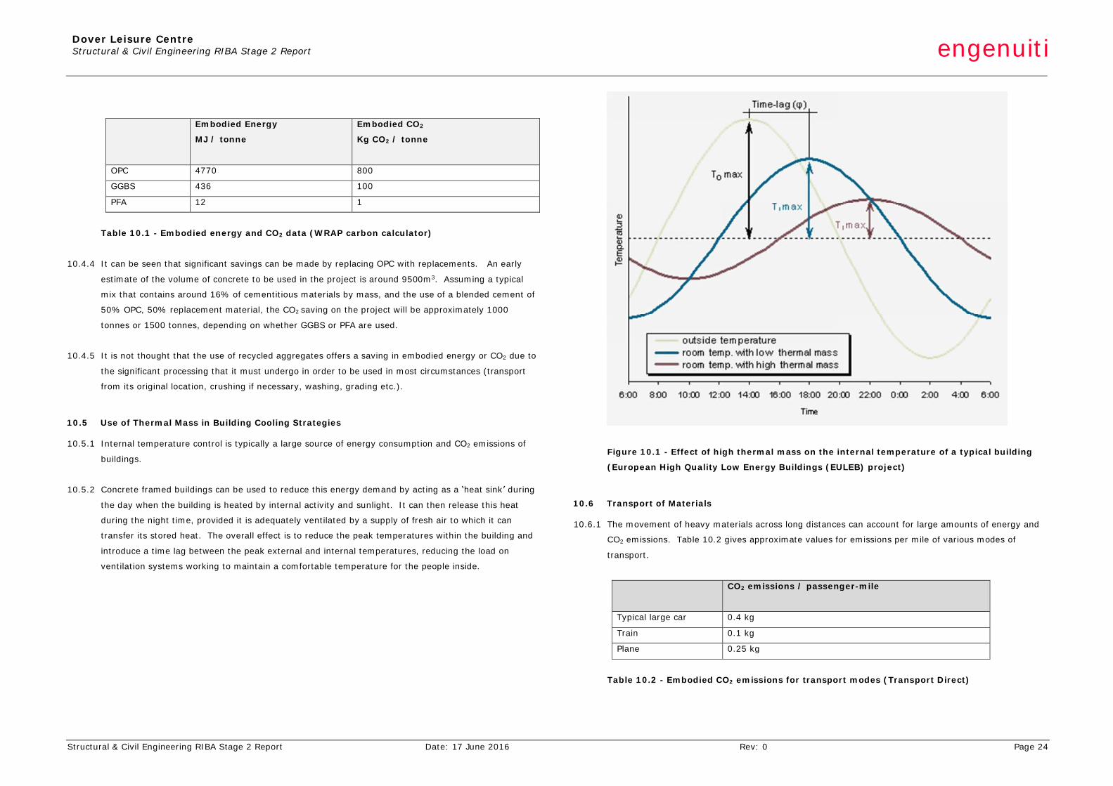
10.5 Use of Thermal Mass in Building Cooling Strategies
10.5.1 Internal temperature control is typically a large source of energy consumption and CO2 emissions of
buildings.
10.5.2 Concrete framed buildings can be used to reduce this energy demand by acting as a ‘heat sink’ during
the day when the building is heated by internal activity and sunlight. It can then release this heat
during the night time, provided it is adequately ventilated by a supply of fresh air to which it can
transfer its stored heat. The overall effect is to reduce the peak temperatures within the building and
introduce a time lag between the peak external and internal temperatures, reducing the load on
ventilation systems working to maintain a comfortable temperature for the people inside.
Figure 10.1 - Effect of high thermal mass on the internal temperature of a typical building
(European High Quality Low Energy Buildings (EULEB) project)
10.6 Transport of Materials
10.6.1 The movement of heavy materials across long distances can account for large amounts of energy and
CO2 emissions. Table 10.2 gives approximate values for emissions per mile of various modes of
transport.
CO2 emissions / passenger-mile
Typical large car 0.4 kg
Train 0.1 kg
Plane 0.25 kg
Table 10.2 - Embodied CO2 emissions for transport modes (Transport Direct)
Dover Leisure Centre Structural & Civil Engineering RIBA Stage 2 Report engenuiti
Structural & Civil Engineering RIBA Stage 2 Report Date: 17 June 2016 Rev: 0 Page 25
10.7 Socio-Economic Factors
10.7.1 Some materials used in construction can be certified under a ‘chain of custody’ scheme, provided the
supplier can demonstrate they source responsibly and have an environmental management system in
place that restricts the environmental impact of their product. The FSC & PEFC certification systems
that applies to all timber used in construction, including plywood formwork panels, is one such scheme
that is now standard practice in the UK. ‘Eco-reinforcement’ is another example, introduced very
recently, that will apply to steel reinforcement used in concrete structures: having the eco-
reinforcement certification will verify the product is made from 100% recycled steel.
10.7.2 There are strong sustainability arguments for using local labour resources wherever possible.
Construction is a major source of employment and it is thought this project will provide work to a large
number of local people. Offering training to local people will increase their capacity to contribute to
their local economy.
Dover Leisure Centre Structural & Civil Engineering RIBA Stage 2 Report engenuiti
Structural & Civil Engineering RIBA Stage 2 Report Date: 17 June 2016 Rev: 0 Page 26
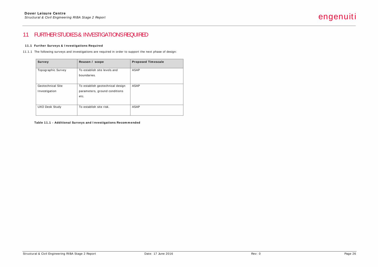
11 FURTHER STUDIES & INVESTIGATIONS REQUIRED
11.1 Further Surveys & Investigations Required
11.1.1 The following surveys and investigations are required in order to support the next phase of design:
Survey Reason / scope Proposed Timescale
Topographic Survey
To establish site levels and
boundaries.
ASAP
Geotechnical Site
Investigation
To establish geotechnical design
parameters, ground conditions
etc.
ASAP
UXO Desk Study
To establish site risk. ASAP
Table 11.1 - Additional Surveys and Investigations Recommended
Dover Leisure Centre Structural & Civil Engineering RIBA Stage 2 Report engenuiti
Structural & Civil Engineering RIBA Stage 2 Report Date: 17 June 2016 Rev: 0 APPENDIX A
APPENDIX A STRUCTURAL & CIVIL ENGINEERING DESIGN CRITERIA & MATERIALS
engenuiti
DOVER LEISURE CENTRE
STRUCTURAL & CIVIL ENGINEERING DESIGN CRITERIA & MATERIALS
for
GT3 Architects
17th June 2016
634-S-REP-002 Rev 0
Engenuiti 2 Maltings Place
Tower Bridge Road London, SE1 3JB
Dover Leisure Centre Structural & Civil Engineering Design Criteria & Materials engenuiti
Structural & Civil Engineering Design Criteria & Materials Date: 17th June 2016 Rev: 0 Page 2
STRUCTURAL & CIVIL ENGINEERING DESIGN CRITERIA & MATERIALS CONTENTS Section Item Page 1 INTRODUCTION 3
2 DESIGN CODES 4
3 GEOTECHNICAL DESIGN PARAMETERS 5
4 LOAD ACTIONS & COMBINATIONS 5
5 PERMANENT ACTIONS 6
6 VARIABLE ACTIONS 6
7 WIND LOADING & SNOW LOADING 7
8 PARAPETS / HANDRAILS LOADING 7
9 STABILITY & ROBUSTNESS 7
10 PARAPETS / HANDRAILS LOADING 7
11 FLOOR VIBRATION 7
12 FIRE RESISTANCE 8
13 TEMPERATURE & HUMIDITY EFFECTS 8
14 MOVEMENT & TOLERNACES 8
15 CONCRETE 8
16 STEEL 9
17 TIMBER 9
18 SWIMMING POOL CONSTRUCTION 9
19 DRAINAGE & HARDSTANDING 9 Revision History
Rev Date Purpose/Status Document Ref. Comments 00 17th June 2016 Draft 634-S-REP-002 Issued for Information
Prepared by: Reviewed & Approved by:
Chris Law
Sarah Curran
Paul Grimes
Senior Engineer Associate Director This document is copyright © The Engenuiti Partnership LLP and is prepared for use by GT3 Architects Limited. The document may not be used by any party, copied or distributed without written approval from The Engenuiti Partnership LLP.
Dover Leisure Centre Structural & Civil Engineering Design Criteria & Materials engenuiti
Structural & Civil Engineering Design Criteria & Materials Date: 17th June 2016 Rev: 0 Page 3
1 INTRODUCTION
1.1 General 1.1.1 Engenuiti has been appointed by GT3 Architects Limited to provide structural & civil engineering design services for
the proposed new Dover Leisure Centre.
1.1.2 The purpose of this Structural & Civil Engineering Design Criteria & Materials report is to describe the structural and civil engineering design criteria of the proposed development and provide outline material specifications to enable GT3 Architects to finalise the design parameters for the project.
1.1.3 This report has been produced for the exclusive use of GT3 Architects Limited and should not be used in whole or in part by any third parties without the express permission of Engenuiti in writing. This report should not be relied upon exclusively for decision-making purposes and should be read in conjunction with other documents and drawings produced by the design team.
1.2 Proposed Development 1.2.1 The proposed leisure centre is located in Whitfield, Dover. The site postcode is CT16 3FH. The site location is south
of Honeywood Parkway and east of The Glenmore Centre.
1.2.2 The site is currently a greenfield location bounded by Honeywood Parkway and a spur road to the east of the site.
1.2.3 The proposed leisure centre is a new build facility. The new facility will be designed around the following accommodation mix:
• 8 lane 25m pool • Learner pool with moveable floor • Wet changing village • Activity zone around a new café space • 4 court sports hall with associated changing • Treatment rooms • Gymnasium • 2 large dance studios • Spinning studio.
1.2.4 At this stage this Design Criteria & Materials report is based around a structural solution of steel frame with long
span cell beam roof, shallow RC foundations and in situ RC swimming pool. The document will be developed as the design evolves.
Dover Leisure Centre Structural & Civil Engineering Design Criteria & Materials engenuiti
Structural & Civil Engineering Design Criteria & Materials Date: 17th June 2016 Rev: 0 Page 4
2 DESIGN CODES
2.1 Design Codes
Eurocode Ref Eurocode National Annex
BS EN 1990:2002+A1:2005 Eurocode - Basis of structural design NA to BS EN 1990:2002
(UK National Annex for Eurocode 0 – Basis of structural design)
BS EN 1991-1-1:2002 Eurocode 1: Actions on structures –
Part 1-1: General actions – Densities, self-weight, imposed loads for buildings
NA to BS EN 1991-1-1:2002
(UK National Annex to Eurocode 1: Actions on structures – Part 1-1: General actions – Densities, …)
BS EN 1991-1-2:2002 Eurocode 1: Actions on structures –
Part 1-2: General actions – Actions on structures exposed to fire
NA to BS EN 1991-1-2:2002 (UK National Annex to Eurocode 1: Actions on structures – Part 1-2: General actions – Actions on structures exposed to fire
BS EN 1991-1-3:2003 Eurocode 1: Actions on structures –
Part 1-3: General actions – Snow Loads
NA to BS EN 1991-1-3:2003 (UK National Annex to Eurocode 1: Actions on structures –
Part 1-3: General actions – Snow Loads)
BS EN 1991-1-4:2005 Eurocode 1: Actions on structures –
Part 1-4: General actions – Wind actions
BS EN 1991-1-5:2003 Eurocode 1: Actions on structures – Part 1.5: General actions – Thermal actions)
NA to BS EN 1991-1-5:2003 (UK National Annex to Eurocode 1: Actions on structures – Part 1.5: General actions – Thermal actions)
BS EN 1991-1-7:2006 Eurocode 1: Actions on structures –
Part 1-7: General actions – Accidental actions
BS EN 1992-1-1:2004 Eurocode 2: Design of concrete structures –
Part 1-1: General rules and rules for buildings
NA to BS EN 1992-1-1:2004 (UK National Annex to Eurocode 2: Design of concrete structures –
Part 1-1: General rules and rules for buildings) (+A1:2009)
BS EN 1992-1-2:2004 Eurocode 2: Design of concrete structures –
Part 1-2: General rules – Structural fire design
NA to BS EN 1992-1-2:2004 (Uk National Annex to Eurocode 2: Design of concrete structures –
Part 1-2: General rules – Structural fire design)
BS EN 197-1:2000+A1:2004+A3:2007
Cement – Part 1: Composition, specifications and conformity criteria for common cements
BS EN 934-2:2009 Admixtures for concrete, mortar and grout Part 2: Concrete admixtures – Definitions, requirements, conformity, marking and labelling
n/a
BS EN 206-1:2000+A1:2004+A2:2005
Concrete – Part 1: Specification, performance, production and conformity
BS 8500-1:2006 BS 8500-2:2006
Eurocode Ref
Eurocode National Annex
BS 8102:2009 Code of practice for protection of below ground structures against water from the ground
BS 8500-1:2006 Concrete – Complementary British Standard to BS EN 206-1 – Part 1: Method of specifying and guidance for the specifier
BS 8500-2:2006 Concrete – Complementary British Standard to BS EN 206-1 – Part 2: Specification for constituent materials and concrete
BRE Special Digest 1:2005 Third Edition
Concrete in aggressive ground n/a
BS EN 1993-1-1:2005 Eurocode 3: Design of steel structures – Part 1-1: General rules and rules for buildings
NA to BS EN 1993-1-1:2005 (UK National Annex to Eurocode 3: Design of steel structures Part 1-1: General rules and rules for buildings) (2008)
BS EN 1993-1-3:2006 Eurocode 3: Design of steel structures – Part 1-3: Cold-formed thin gauge members and sheeting
BS EN 1993-1-5:2006 Eurocode 3: Design of steel structures – Part 1-5: Plated structural elements
BS EN 1993-1-8:2005 Eurocode 3: Design of steel structures – Part 1-8: Design of joints
NA to BS EN 1993-1-8:2005 (UK National Annex to Eurocode 3: Design of steel structures Part 1-8: Design of joints) (2008)
BS EN 1994-1-1:2004 Eurocode 4: Design of composite steel and concrete structures – Part 1-1: General rules and rules for buildings
NA to BS EN 1994-1-1:2004 (UK National Annex to Eurocode 4: Design of composite steel and concrete structures – Part 1-1: General rules and rules for buildings) (2008)
BS EN 1995-1-1 Eurocode 5: Design of timber structures – Part 1-1: General – Common rules and rules for buildings
BS EN 1995-1-2 Eurocode 5: Design of timber structures – Part 1-2: General – Structural fire design
BS EN 1996-1-1:2005 Eurocode 6 - Design of masonry structures – Part 1-1: General rules for reinforced and unreinforced masonry structures
NA to BS EN 1996-1-1:2005 (UK National Annex to Eurocode 6 - Design of masonry structures – Part 1-1: General rules for reinforced and unreinforced masonry structures) (2007)
BS EN 1997-1:2004 Eurocode 7: Geotechnical design – Part 1: General rules
NA to BS EN 1997-1:2004
(UK National Annex to Eurocode 7: Geotechnical design – Part 1: General rules)
BS EN 1997-2:2007 Eurocode 7: Geotechnical design – Part 2: Ground investigation and testing
Dover Leisure Centre Structural & Civil Engineering Design Criteria & Materials engenuiti
Structural & Civil Engineering Design Criteria & Materials Date: 17th June 2016 Rev: 0 Page 5
3 GEOTECHNICAL DESIGN PARAMETERS The following values have been taken from the ??? SI Report (TBC).
• SI included TBC
• Site Profile TBC
• The British Geological Survey (BGS) online map indicates that the sites bedrock geology is Margate Chalk Member. The sites superficial deposits are of Clay with flints formation, consisting of clay, silt sand and gravel.
• Concrete sulphate class Ds-1 and AC-1 required? TBC. Ground contamination TBC. • Ground gases TBC
4 LOAD ACTIONS & COMBINATIONS
4.1 Ultimate Limit States (BS EN 1990:2002, Section 6.4)
Combinations of actions for persistent or transient design situations (BS EN 1990:2002, Cl. 6.4.3.2, Eq. 6.10):
∑ ∑≥ ≥
+++1 1
,,0,1,1,,,j i
ikiiQkQPjkjG QQPG ψγγγγ
Combinations of actions for accidental design situations (BS EN 1990:2002, Cl. 6.4.3.3, Eq. 6.11a/b):
∑ ∑≥ ≥
++++1 1
,,21,1,21,1, )(j i
ikikdjk QQorAPG ψψψ
4.2 Serviceability Limit States (BS EN 1990:2002, Section 6.5)
Characteristic combination used for irreversible limit states (BS EN 1990:2002, Cl. 6.5.3, Eq. 6.14a/b):
∑ ∑≥ ≥
+++1 1
,,01,,j i
ikikjk QQPG ψ
Frequent combination used for reversible limit states (BS EN 1990:2002, Cl. 6.5.3, Eq. 6.15a/b)(i.e., temperature loads):
∑ ∑≥ ≥
+++1 1
,,21,1,1,j i
ikikjk QQPG ψψ
Quasi-permanent combination used for long-term effects and the appearance of the structure (BS EN 1990:2002, Cl. 6.5.3, Eq. 6.16a/b) (i.e., long-term deflections [for reinforced concrete floor framing] which include creep and shrinkage effects):
∑ ∑≥ ≥
++1 1
,,2,j i
ikijk QPG ψ
where: Gk,j = characteristic value of permanent action j (i.e., self-weight or superimposed dead load)
P = value of a prestressing action Ad = design value of accidental action AEd = E in load combinations below = design value of seismic action = γIAEk where AEk is characteristic value of seismic action Qk,1 = characteristic value of leading variable action 1 (e.g., Live, Wind, Temperature, etc.) Qk,i = value of accompanying variable action i γG,j = partial factor for permanent action j γQ,1 = partial factor for leading variable action 1 γQ,i = partial factor for accompanying variable action i Ψ0 = factor for combination value of a variable action Ψ1 = factor for frequent value of a variable action Ψ2 = factor for quasi-permanent value of a variable action
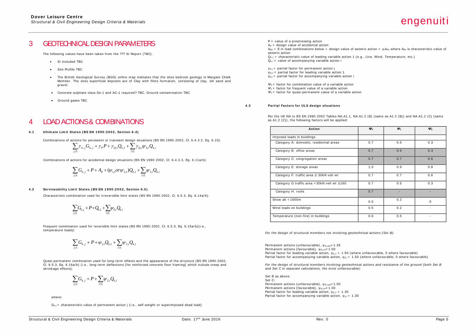
4.3 Partial Factors for ULS design situations
Per the UK NA to BS EN 1990:2002 Tables NA.A1.1, NA.A1.2 (B) (same as A1.2 (B)) and NA.A1.2 (C) (same as A1.2 (C)), the following factors will be applied:
Action
Ψ0 Ψ1 Ψ2
Imposed loads in buildings
Category A: domestic, residential areas
0.7 0.5 0.3
Category B: office areas
0.7 0.5 0.3
Category C: congregation areas
0.7 0.7 0.6
Category E: storage areas
1.0 0.9 0.8
Category F: traffic area ≤ 30kN veh wt
0.7 0.7 0.6
Category G traffic area >30kN veh wt ≤160
0.7 0.5 0.3
Category H: roofs
0.7 - -
Snow alt <1000m 0.5 0.2 0
Wind loads on buildings
0.5 0.2 -
Temperature (non-fire) in buildings
0.6 0.5 -
For the design of structural members not involving geotechnical actions (Set B):
Permanent actions (unfavourable), γGj,sup=1.35 Permanent actions (favourable), γGj,inf=1.00 Partial factor for leading variable action, γQ,1 = 1.50 (where unfavourable, 0 where favourable) Partial factor for accompanying variable action, γQ,i = 1.50 (where unfavourable, 0 where favourable)
For the design of structural members involving geotechnical actions and resistance of the ground (both Set B and Set C in separate calculations, the most unfavourable): Set B as above. Set C: Permanent actions (unfavourable), γGj,sup=1.00 Permanent actions (favourable), γGj,inf=1.00 Partial factor for leading variable action, γQ,1 = 1.30 Partial factor for accompanying variable action, γQ,i = 1.30
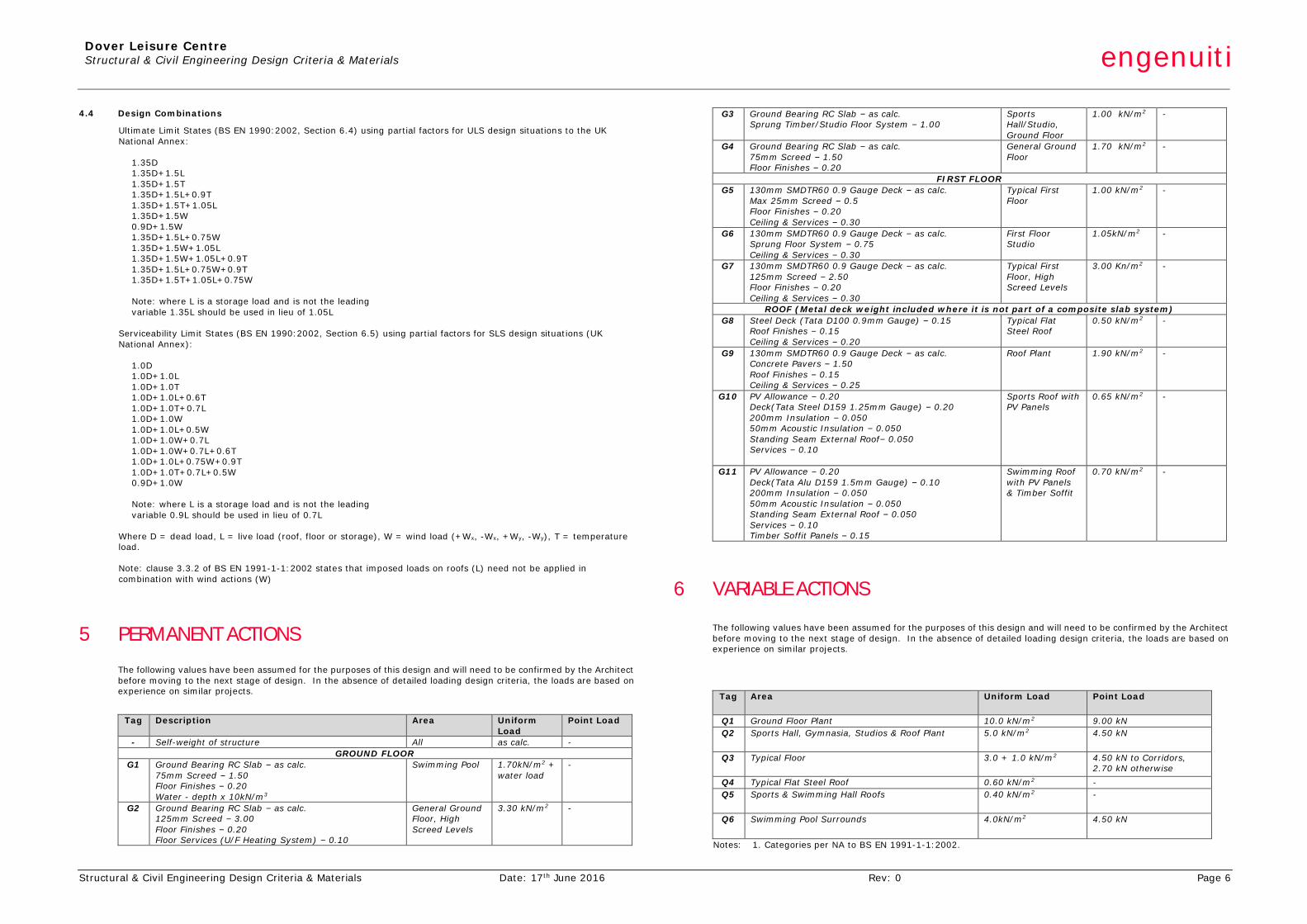
Dover Leisure Centre Structural & Civil Engineering Design Criteria & Materials engenuiti
Structural & Civil Engineering Design Criteria & Materials Date: 17th June 2016 Rev: 0 Page 6
4.4 Design Combinations
Ultimate Limit States (BS EN 1990:2002, Section 6.4) using partial factors for ULS design situations to the UK National Annex:
1.35D 1.35D+1.5L 1.35D+1.5T 1.35D+1.5L+0.9T 1.35D+1.5T+1.05L 1.35D+1.5W 0.9D+1.5W 1.35D+1.5L+0.75W 1.35D+1.5W+1.05L 1.35D+1.5W+1.05L+0.9T 1.35D+1.5L+0.75W+0.9T 1.35D+1.5T+1.05L+0.75W Note: where L is a storage load and is not the leading variable 1.35L should be used in lieu of 1.05L
Serviceability Limit States (BS EN 1990:2002, Section 6.5) using partial factors for SLS design situations (UK National Annex):
1.0D 1.0D+1.0L 1.0D+1.0T 1.0D+1.0L+0.6T 1.0D+1.0T+0.7L 1.0D+1.0W 1.0D+1.0L+0.5W 1.0D+1.0W+0.7L 1.0D+1.0W+0.7L+0.6T 1.0D+1.0L+0.75W+0.9T 1.0D+1.0T+0.7L+0.5W 0.9D+1.0W Note: where L is a storage load and is not the leading variable 0.9L should be used in lieu of 0.7L
Where D = dead load, L = live load (roof, floor or storage), W = wind load (+Wx, -Wx, +Wy, -Wy), T = temperature load. Note: clause 3.3.2 of BS EN 1991-1-1:2002 states that imposed loads on roofs (L) need not be applied in combination with wind actions (W)
5 PERMANENT ACTIONS
The following values have been assumed for the purposes of this design and will need to be confirmed by the Architect before moving to the next stage of design. In the absence of detailed loading design criteria, the loads are based on experience on similar projects.
Tag Description
Area Uniform Load
Point Load
- Self-weight of structure All as calc. - GROUND FLOOR
G1 Ground Bearing RC Slab – as calc. 75mm Screed – 1.50 Floor Finishes – 0.20 Water - depth x 10kN/m3
Swimming Pool 1.70kN/m2 + water load
-
G2 Ground Bearing RC Slab – as calc. 125mm Screed – 3.00 Floor Finishes – 0.20 Floor Services (U/F Heating System) – 0.10
General Ground Floor, High Screed Levels
3.30 kN/m2 -
G3 Ground Bearing RC Slab – as calc. Sprung Timber/Studio Floor System – 1.00
Sports Hall/Studio, Ground Floor
1.00 kN/m2 -
G4 Ground Bearing RC Slab – as calc. 75mm Screed – 1.50 Floor Finishes – 0.20
General Ground Floor
1.70 kN/m2 -
FIRST FLOOR G5 130mm SMDTR60 0.9 Gauge Deck – as calc.
Max 25mm Screed – 0.5 Floor Finishes – 0.20 Ceiling & Services – 0.30
Typical First Floor
1.00 kN/m2 -
G6 130mm SMDTR60 0.9 Gauge Deck – as calc. Sprung Floor System – 0.75 Ceiling & Services – 0.30
First Floor Studio
1.05kN/m2 -
G7 130mm SMDTR60 0.9 Gauge Deck – as calc. 125mm Screed – 2.50 Floor Finishes – 0.20 Ceiling & Services – 0.30
Typical First Floor, High Screed Levels
3.00 Kn/m2 -
ROOF (Metal deck weight included where it is not part of a composite slab system) G8 Steel Deck (Tata D100 0.9mm Gauge) – 0.15
Roof Finishes – 0.15 Ceiling & Services – 0.20
Typical Flat Steel Roof
0.50 kN/m2 -
G9 130mm SMDTR60 0.9 Gauge Deck – as calc. Concrete Pavers – 1.50 Roof Finishes – 0.15 Ceiling & Services – 0.25
Roof Plant 1.90 kN/m2 -
G10 PV Allowance – 0.20 Deck(Tata Steel D159 1.25mm Gauge) – 0.20 200mm Insulation – 0.050 50mm Acoustic Insulation – 0.050 Standing Seam External Roof– 0.050 Services – 0.10
Sports Roof with PV Panels
0.65 kN/m2
-
G11 PV Allowance – 0.20 Deck(Tata Alu D159 1.5mm Gauge) – 0.10 200mm Insulation – 0.050 50mm Acoustic Insulation – 0.050 Standing Seam External Roof – 0.050 Services – 0.10 Timber Soffit Panels – 0.15
Swimming Roof with PV Panels & Timber Soffit
0.70 kN/m2
-
6 VARIABLE ACTIONS The following values have been assumed for the purposes of this design and will need to be confirmed by the Architect before moving to the next stage of design. In the absence of detailed loading design criteria, the loads are based on experience on similar projects.
Tag Area Uniform Load Point Load
Q1 Ground Floor Plant 10.0 kN/m2 9.00 kN Q2 Sports Hall, Gymnasia, Studios & Roof Plant 5.0 kN/m2 4.50 kN
Q3 Typical Floor 3.0 + 1.0 kN/m2 4.50 kN to Corridors, 2.70 kN otherwise
Q4 Typical Flat Steel Roof 0.60 kN/m2 - Q5 Sports & Swimming Hall Roofs 0.40 kN/m2 -
Q6 Swimming Pool Surrounds 4.0kN/m2 4.50 kN
Notes: 1. Categories per NA to BS EN 1991-1-1:2002.
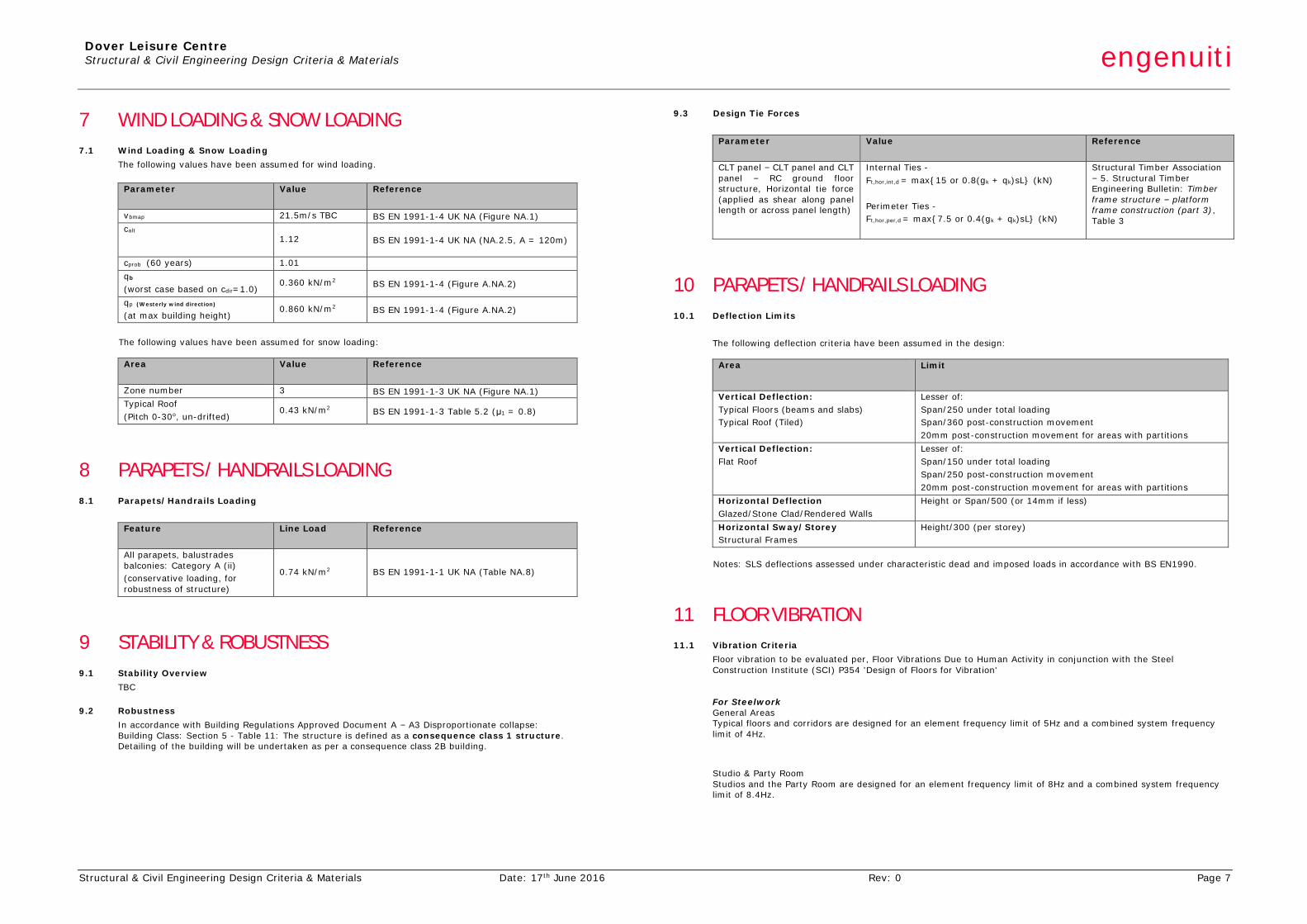
Dover Leisure Centre Structural & Civil Engineering Design Criteria & Materials engenuiti
Structural & Civil Engineering Design Criteria & Materials Date: 17th June 2016 Rev: 0 Page 7
7 WIND LOADING & SNOW LOADING 7.1 Wind Loading & Snow Loading
The following values have been assumed for wind loading.
Parameter
Value Reference
vbmap 21.5m/s TBC BS EN 1991-1-4 UK NA (Figure NA.1) calt
1.12 BS EN 1991-1-4 UK NA (NA.2.5, A = 120m)
cprob (60 years) 1.01 qb
(worst case based on cdir=1.0) 0.360 kN/m2 BS EN 1991-1-4 (Figure A.NA.2)
qp (Westerly wind direction)
(at max building height) 0.860 kN/m2 BS EN 1991-1-4 (Figure A.NA.2)
The following values have been assumed for snow loading:
Area
Value Reference
Zone number 3 BS EN 1991-1-3 UK NA (Figure NA.1) Typical Roof (Pitch 0-30o, un-drifted)
0.43 kN/m2 BS EN 1991-1-3 Table 5.2 (μ1 = 0.8)
8 PARAPETS / HANDRAILS LOADING 8.1 Parapets/Handrails Loading
Feature
Line Load Reference
All parapets, balustrades balconies: Category A (ii) (conservative loading, for robustness of structure)
0.74 kN/m2 BS EN 1991-1-1 UK NA (Table NA.8)
9 STABILITY & ROBUSTNESS 9.1 Stability Overview
TBC
9.2 Robustness In accordance with Building Regulations Approved Document A – A3 Disproportionate collapse: Building Class: Section 5 - Table 11: The structure is defined as a consequence class 1 structure. Detailing of the building will be undertaken as per a consequence class 2B building.
9.3 Design Tie Forces
Parameter
Value Reference
CLT panel – CLT panel and CLT panel – RC ground floor structure, Horizontal tie force (applied as shear along panel length or across panel length)
Internal Ties - Ft,hor,int,d = max{15 or 0.8(gk + qk)sL} (kN) Perimeter Ties - Ft,hor,per,d = max{7.5 or 0.4(gk + qk)sL} (kN)
Structural Timber Association – 5. Structural Timber Engineering Bulletin: Timber frame structure – platform frame construction (part 3), Table 3
10 PARAPETS / HANDRAILS LOADING 10.1 Deflection Limits
The following deflection criteria have been assumed in the design:
Area
Limit
Vertical Deflection: Typical Floors (beams and slabs) Typical Roof (Tiled)
Lesser of: Span/250 under total loading Span/360 post-construction movement 20mm post-construction movement for areas with partitions
Vertical Deflection: Flat Roof
Lesser of: Span/150 under total loading Span/250 post-construction movement 20mm post-construction movement for areas with partitions
Horizontal Deflection Glazed/Stone Clad/Rendered Walls
Height or Span/500 (or 14mm if less)
Horizontal Sway/Storey Structural Frames
Height/300 (per storey)
Notes: SLS deflections assessed under characteristic dead and imposed loads in accordance with BS EN1990.
11 FLOOR VIBRATION 11.1 Vibration Criteria
Floor vibration to be evaluated per, Floor Vibrations Due to Human Activity in conjunction with the Steel Construction Institute (SCI) P354 'Design of Floors for Vibration'
For Steelwork General Areas Typical floors and corridors are designed for an element frequency limit of 5Hz and a combined system frequency limit of 4Hz.
Studio & Party Room Studios and the Party Room are designed for an element frequency limit of 8Hz and a combined system frequency limit of 8.4Hz.
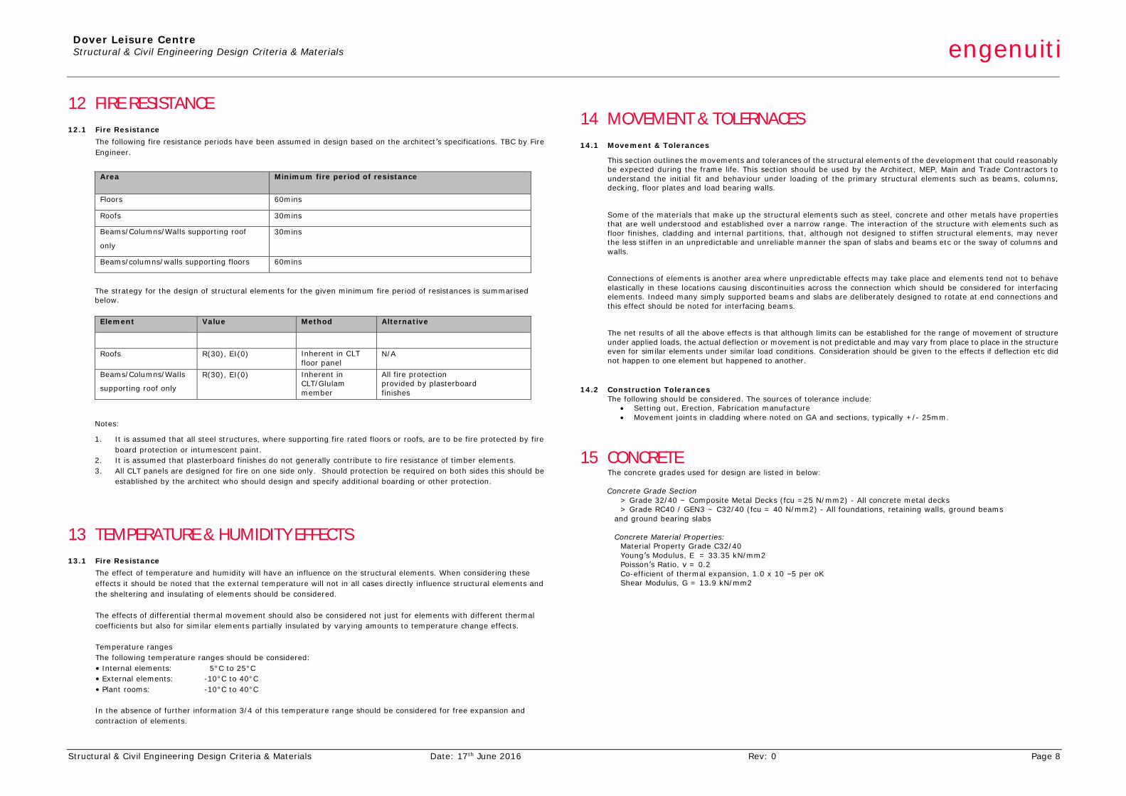
Dover Leisure Centre Structural & Civil Engineering Design Criteria & Materials engenuiti
Structural & Civil Engineering Design Criteria & Materials Date: 17th June 2016 Rev: 0 Page 8
12 FIRE RESISTANCE 12.1 Fire Resistance
The following fire resistance periods have been assumed in design based on the architect’s specifications. TBC by Fire Engineer.
Area
Minimum fire period of resistance
Floors 60mins
Roofs 30mins
Beams/Columns/Walls supporting roof
only
30mins
Beams/columns/walls supporting floors 60mins
The strategy for the design of structural elements for the given minimum fire period of resistances is summarised below.
Element Value Method Alternative
Roofs R(30), EI(0) Inherent in CLT floor panel
N/A
Beams/Columns/Walls
supporting roof only
R(30), EI(0) Inherent in CLT/Glulam member
All fire protection provided by plasterboard finishes
Notes:
1. It is assumed that all steel structures, where supporting fire rated floors or roofs, are to be fire protected by fire board protection or intumescent paint.
2. It is assumed that plasterboard finishes do not generally contribute to fire resistance of timber elements. 3. All CLT panels are designed for fire on one side only. Should protection be required on both sides this should be
established by the architect who should design and specify additional boarding or other protection.
13 TEMPERATURE & HUMIDITY EFFECTS 13.1 Fire Resistance
The effect of temperature and humidity will have an influence on the structural elements. When considering these effects it should be noted that the external temperature will not in all cases directly influence structural elements and the sheltering and insulating of elements should be considered. The effects of differential thermal movement should also be considered not just for elements with different thermal coefficients but also for similar elements partially insulated by varying amounts to temperature change effects. Temperature ranges The following temperature ranges should be considered: • Internal elements: 5°C to 25°C • External elements: -10°C to 40°C • Plant rooms: -10°C to 40°C In the absence of further information 3/4 of this temperature range should be considered for free expansion and contraction of elements.
14 MOVEMENT & TOLERNACES 14.1 Movement & Tolerances
This section outlines the movements and tolerances of the structural elements of the development that could reasonably be expected during the frame life. This section should be used by the Architect, MEP, Main and Trade Contractors to understand the initial fit and behaviour under loading of the primary structural elements such as beams, columns, decking, floor plates and load bearing walls.
Some of the materials that make up the structural elements such as steel, concrete and other metals have properties that are well understood and established over a narrow range. The interaction of the structure with elements such as floor finishes, cladding and internal partitions, that, although not designed to stiffen structural elements, may never the less stiffen in an unpredictable and unreliable manner the span of slabs and beams etc or the sway of columns and walls.
Connections of elements is another area where unpredictable effects may take place and elements tend not to behave elastically in these locations causing discontinuities across the connection which should be considered for interfacing elements. Indeed many simply supported beams and slabs are deliberately designed to rotate at end connections and this effect should be noted for interfacing beams.
The net results of all the above effects is that although limits can be established for the range of movement of structure under applied loads, the actual deflection or movement is not predictable and may vary from place to place in the structure even for similar elements under similar load conditions. Consideration should be given to the effects if deflection etc did not happen to one element but happened to another.
14.2 Construction Tolerances
The following should be considered. The sources of tolerance include: • Setting out, Erection, Fabrication manufacture • Movement joints in cladding where noted on GA and sections, typically +/- 25mm.
15 CONCRETE The concrete grades used for design are listed in below:
Concrete Grade Section
> Grade 32/40 ~ Composite Metal Decks (fcu =25 N/mm2) - All concrete metal decks > Grade RC40 / GEN3 ~ C32/40 (fcu = 40 N/mm2) - All foundations, retaining walls, ground beams
and ground bearing slabs
Concrete Material Properties: Material Property Grade C32/40 Young’s Modulus, E = 33.35 kN/mm2 Poisson’s Ratio, ν = 0.2 Co-efficient of thermal expansion, 1.0 x 10 –5 per oK Shear Modulus, G = 13.9 kN/mm2
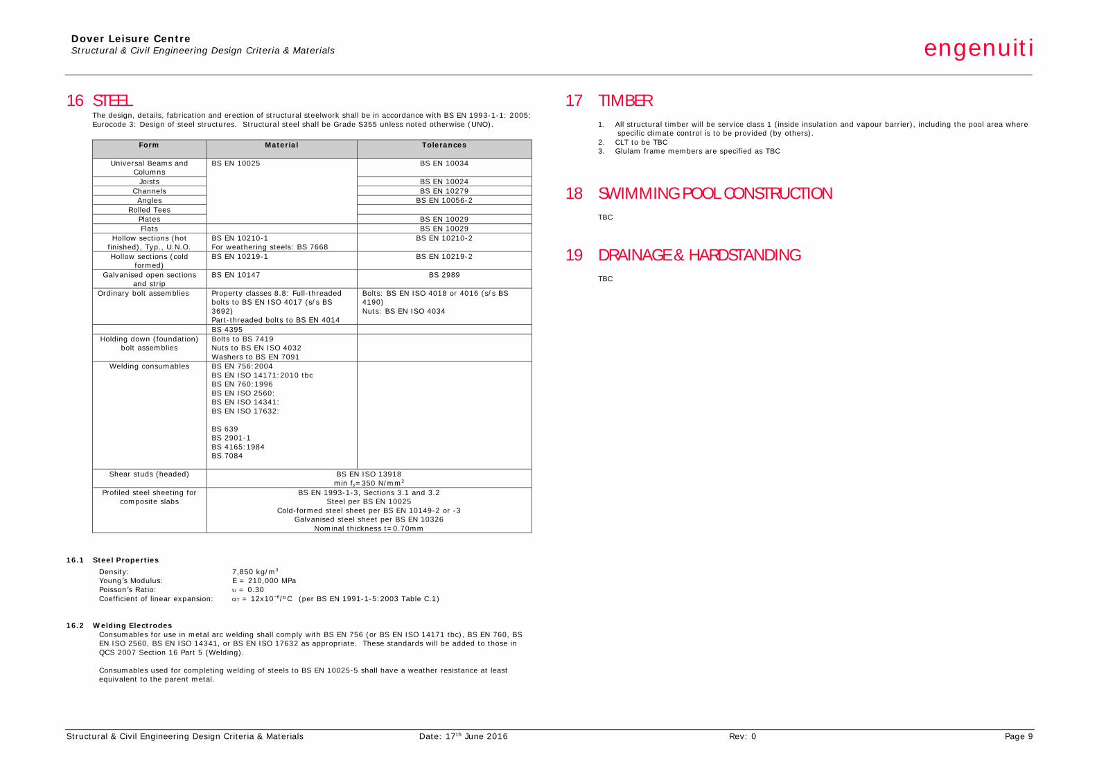
Dover Leisure Centre Structural & Civil Engineering Design Criteria & Materials engenuiti
Structural & Civil Engineering Design Criteria & Materials Date: 17th June 2016 Rev: 0 Page 9
16 STEEL The design, details, fabrication and erection of structural steelwork shall be in accordance with BS EN 1993-1-1: 2005: Eurocode 3: Design of steel structures. Structural steel shall be Grade S355 unless noted otherwise (UNO).
Form
Material Tolerances
Universal Beams and Columns
BS EN 10025 BS EN 10034
Joists BS EN 10024 Channels BS EN 10279 Angles BS EN 10056-2
Rolled Tees Plates BS EN 10029 Flats BS EN 10029
Hollow sections (hot finished), Typ., U.N.O.
BS EN 10210-1 For weathering steels: BS 7668
BS EN 10210-2
Hollow sections (cold formed)
BS EN 10219-1 BS EN 10219-2
Galvanised open sections and strip
BS EN 10147 BS 2989
Ordinary bolt assemblies Property classes 8.8: Full-threaded bolts to BS EN ISO 4017 (s/s BS 3692) Part-threaded bolts to BS EN 4014
Bolts: BS EN ISO 4018 or 4016 (s/s BS 4190) Nuts: BS EN ISO 4034
BS 4395 Holding down (foundation)
bolt assemblies Bolts to BS 7419 Nuts to BS EN ISO 4032 Washers to BS EN 7091
Welding consumables BS EN 756:2004 BS EN ISO 14171:2010 tbc BS EN 760:1996 BS EN ISO 2560: BS EN ISO 14341: BS EN ISO 17632: BS 639 BS 2901-1 BS 4165:1984 BS 7084
Shear studs (headed) BS EN ISO 13918 min fy=350 N/mm2
Profiled steel sheeting for composite slabs
BS EN 1993-1-3, Sections 3.1 and 3.2 Steel per BS EN 10025
Cold-formed steel sheet per BS EN 10149-2 or -3 Galvanised steel sheet per BS EN 10326
Nominal thickness t=0.70mm
16.1 Steel Properties Density: 7,850 kg/m3 Young’s Modulus: E = 210,000 MPa Poisson’s Ratio: υ = 0.30 Coefficient of linear expansion: αT = 12x10–6/ºC (per BS EN 1991-1-5:2003 Table C.1)
16.2 Welding Electrodes
Consumables for use in metal arc welding shall comply with BS EN 756 (or BS EN ISO 14171 tbc), BS EN 760, BS EN ISO 2560, BS EN ISO 14341, or BS EN ISO 17632 as appropriate. These standards will be added to those in QCS 2007 Section 16 Part 5 (Welding). Consumables used for completing welding of steels to BS EN 10025-5 shall have a weather resistance at least equivalent to the parent metal.
17 TIMBER
1. All structural timber will be service class 1 (inside insulation and vapour barrier), including the pool area where specific climate control is to be provided (by others).
2. CLT to be TBC 3. Glulam frame members are specified as TBC
18 SWIMMING POOL CONSTRUCTION
TBC
19 DRAINAGE & HARDSTANDING
TBC
Dover Leisure Centre Structural & Civil Engineering RIBA Stage 2 Report engenuiti
Structural & Civil Engineering RIBA Stage 2 Report Date: 17 June 2016 Rev: 0 APPENDIX B
APPENDIX B STRUCTURAL ENGINEERING SKETCHES
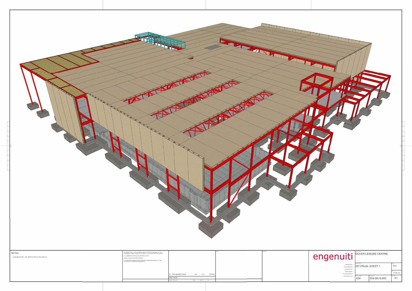
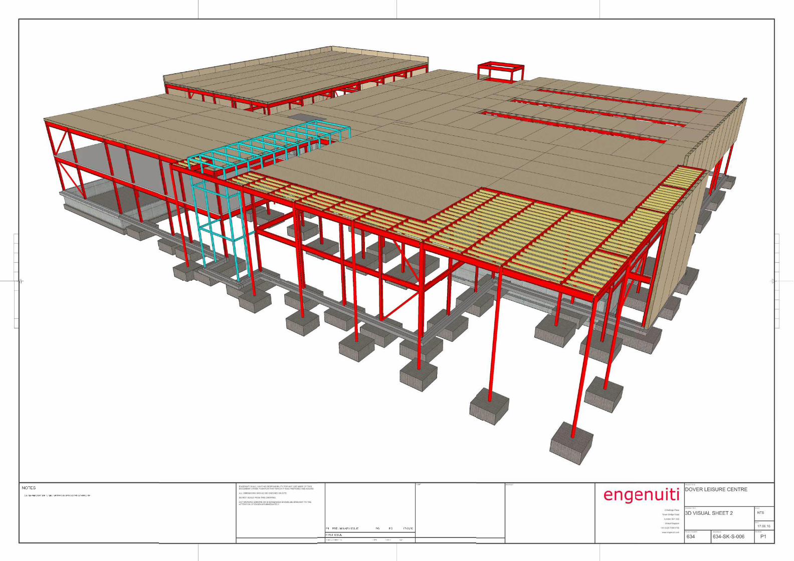
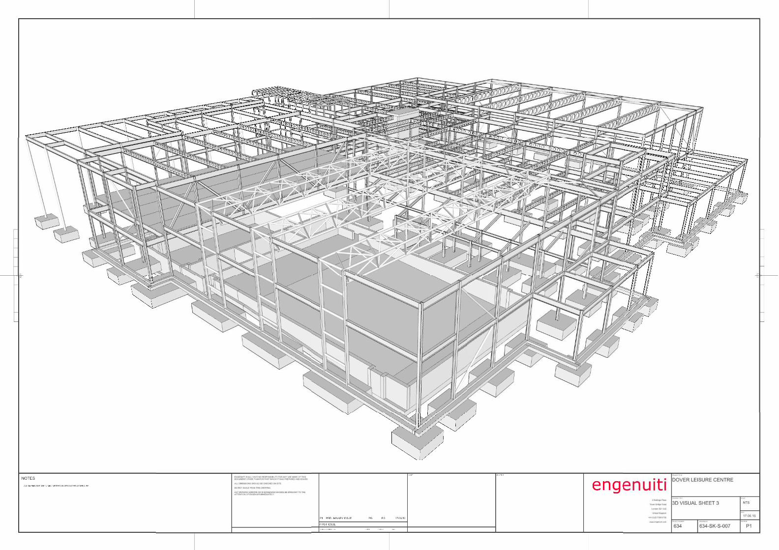
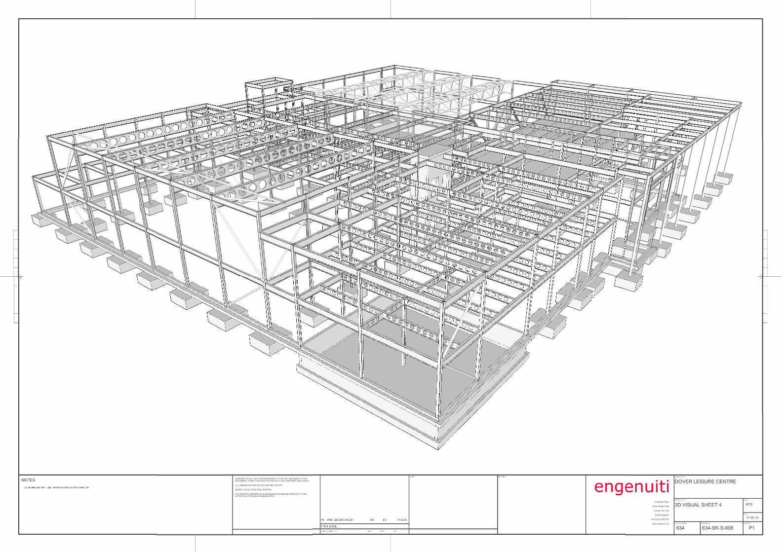
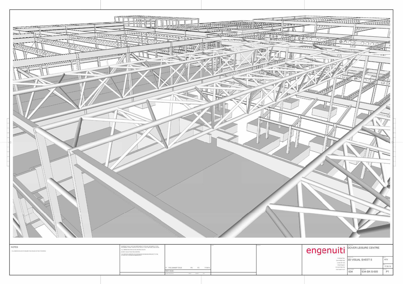
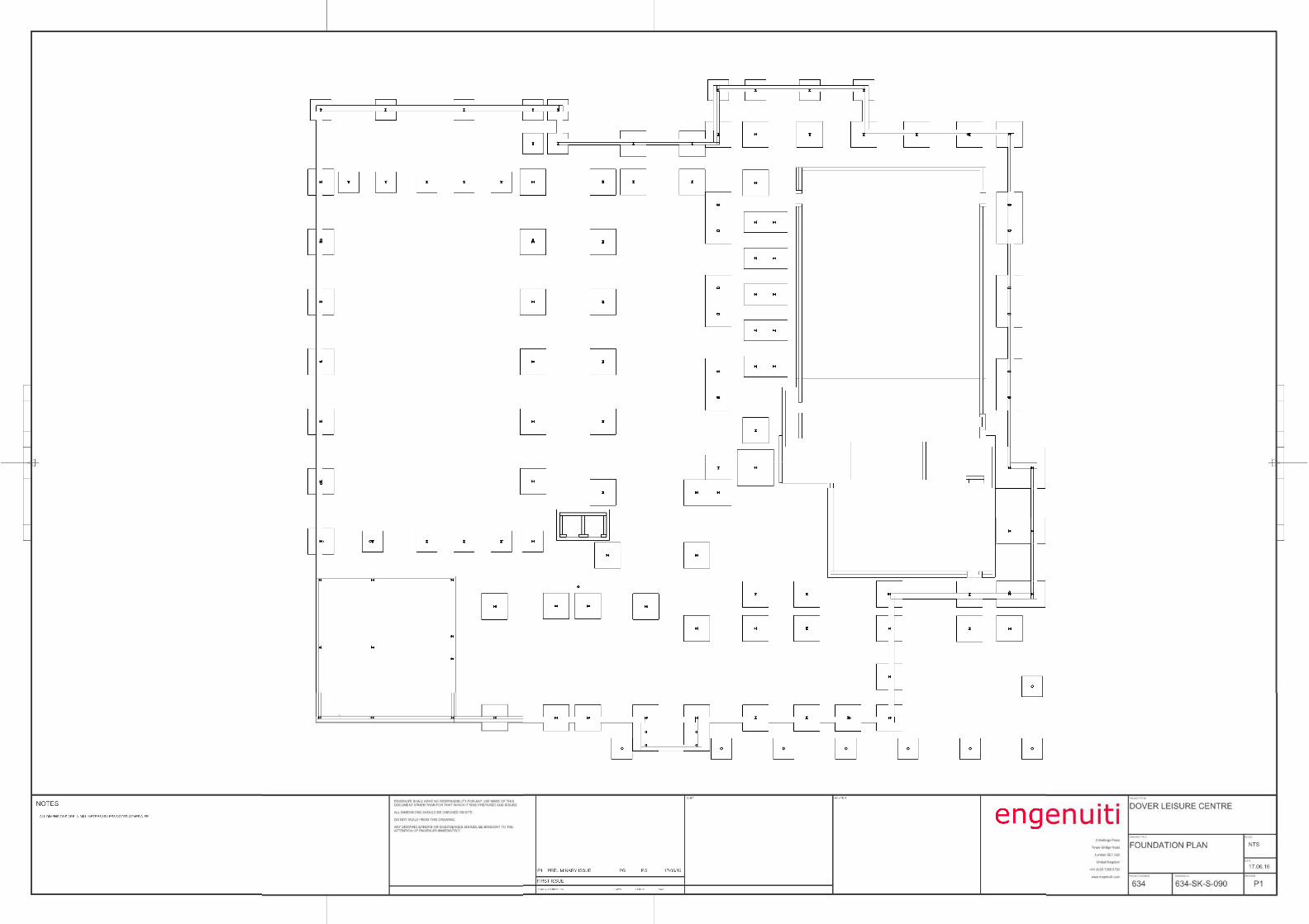
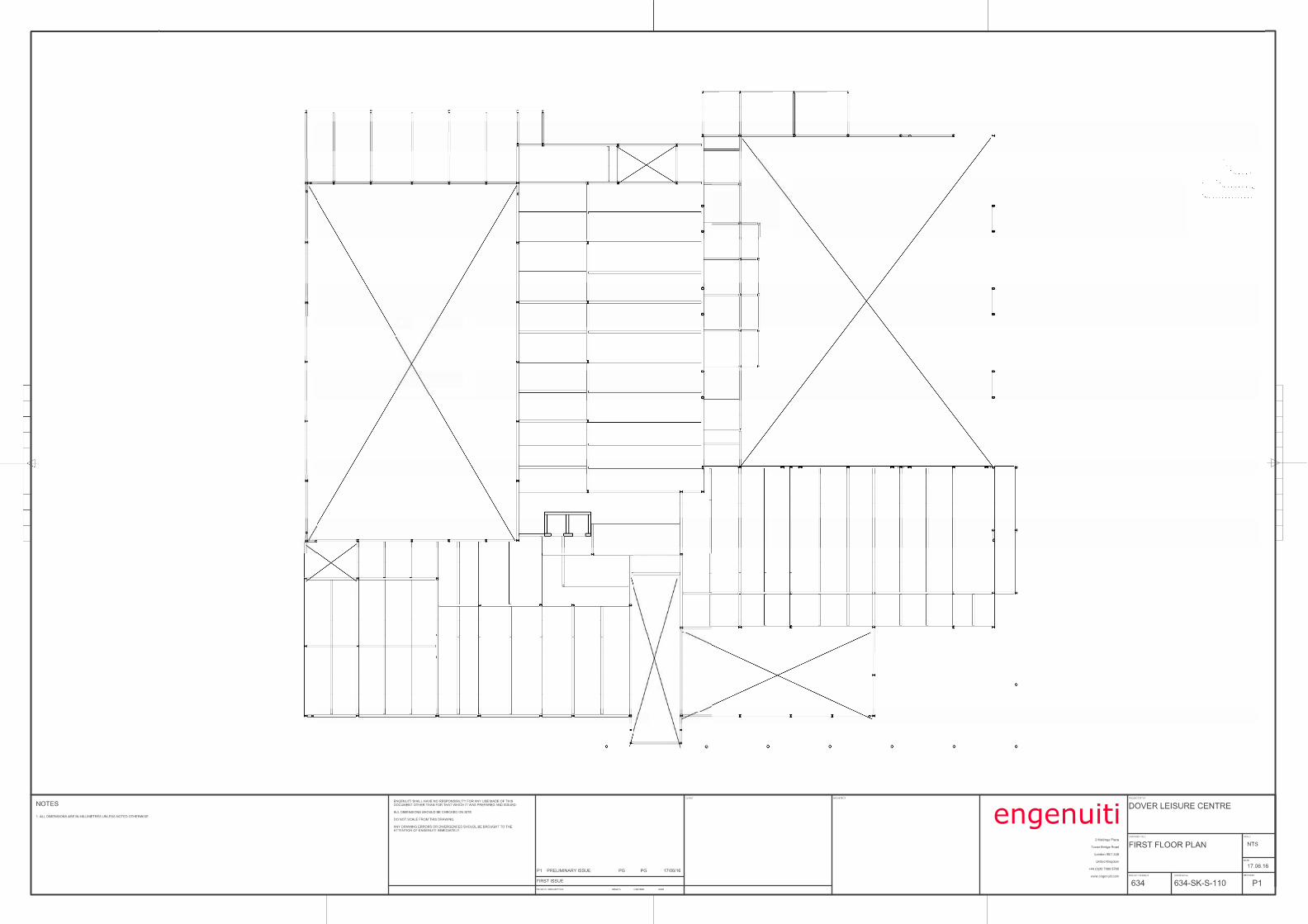
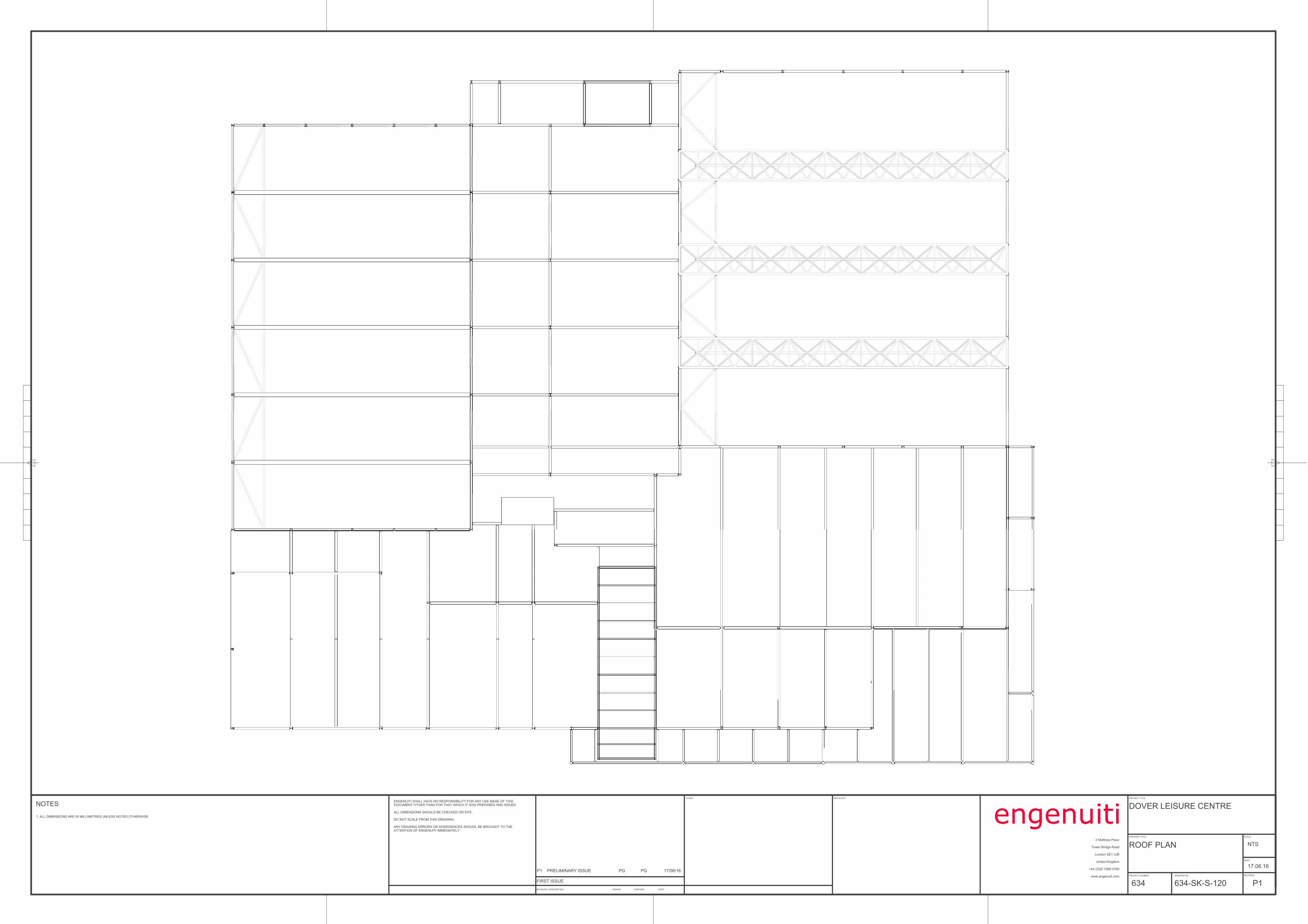
P1 PRELIMINARY ISSUE PG PG 17/06/16
ROOF PLAN
PROJECT TITLE
DRAWING TITLE
PROJECT NUMBER DRAWING No
SCALE
DATE
REVISION
DOVER LEISURE CENTRE
engenuitiNTS
634-SK-S-120
17.06.16
P1
2 Maltings Place
Tower Bridge Road
London SE1 3JB
United Kingdom
+44 (0)20 7089 5760
www.engenuiti.com
CLIENT ARCHITECT
REVISION / DESCRIPTION DRAWN DATECHECKED
FIRST ISSUE
ENGENUITI SHALL HAVE NO RESPONSIBILITY FOR ANY USE MADE OF THIS DOCUMENT OTHER THAN FOR THAT WHICH IT WAS PREPARED AND ISSUED.
ALL DIMENSIONS SHOULD BE CHECKED ON SITE.
DO NOT SCALE FROM THIS DRAWING.
ANY DRAWING ERRORS OR DIVERGENCES SHOUDL BE BROUGHT TO THE ATTENTION OF ENGENUITI IMMEDIATELY.
1. ALL DIMENSIONS ARE IN MILLIMETRES UNLESS NOTED OTHERWISE
NOTES
634
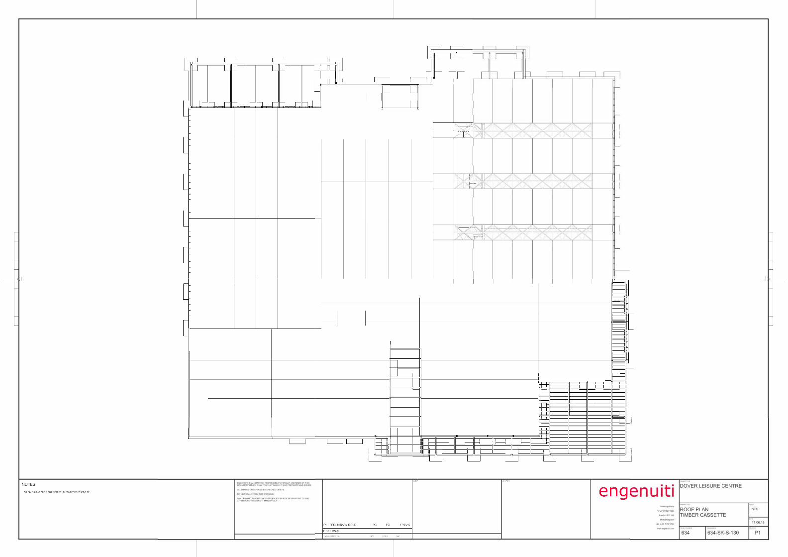
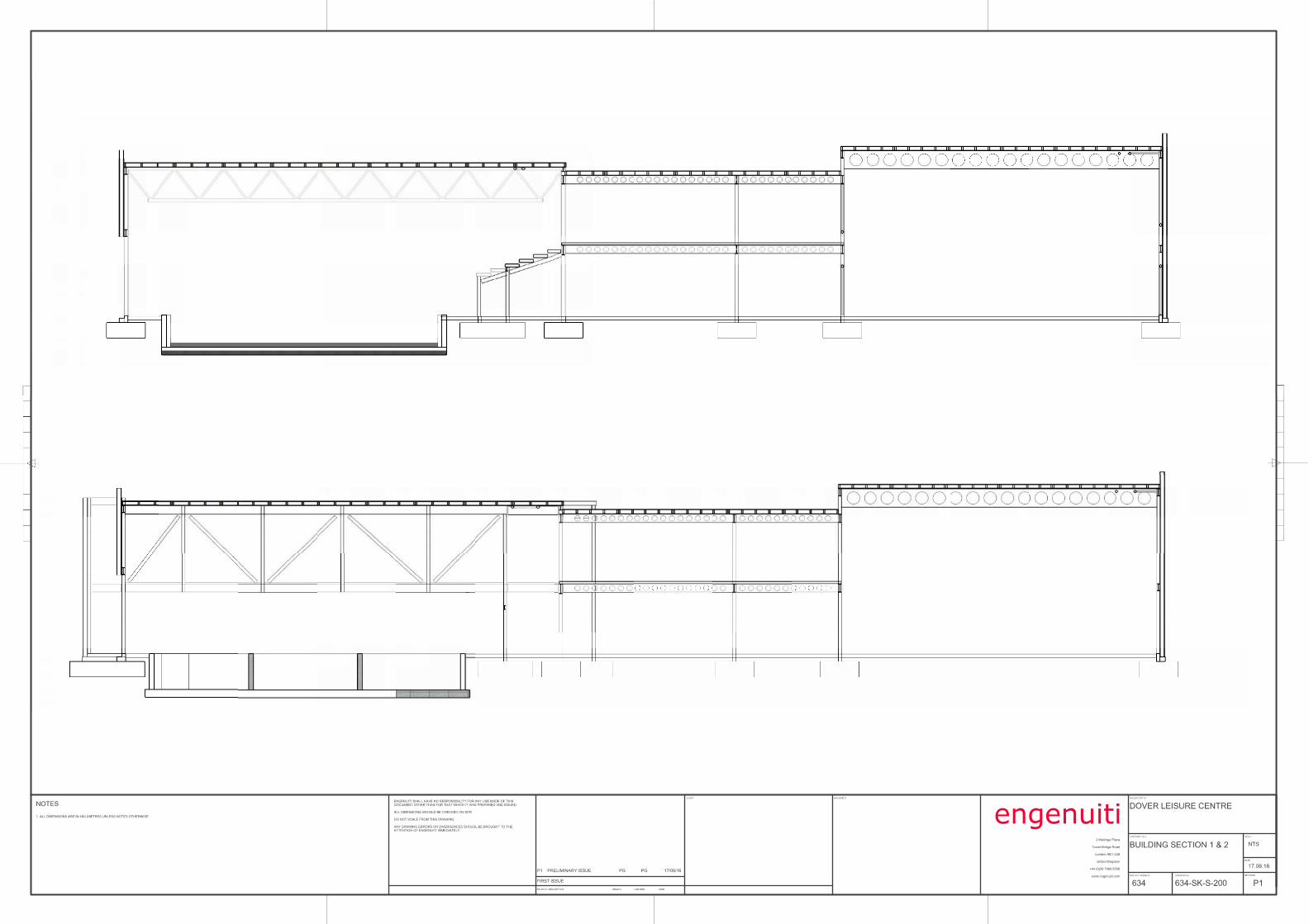
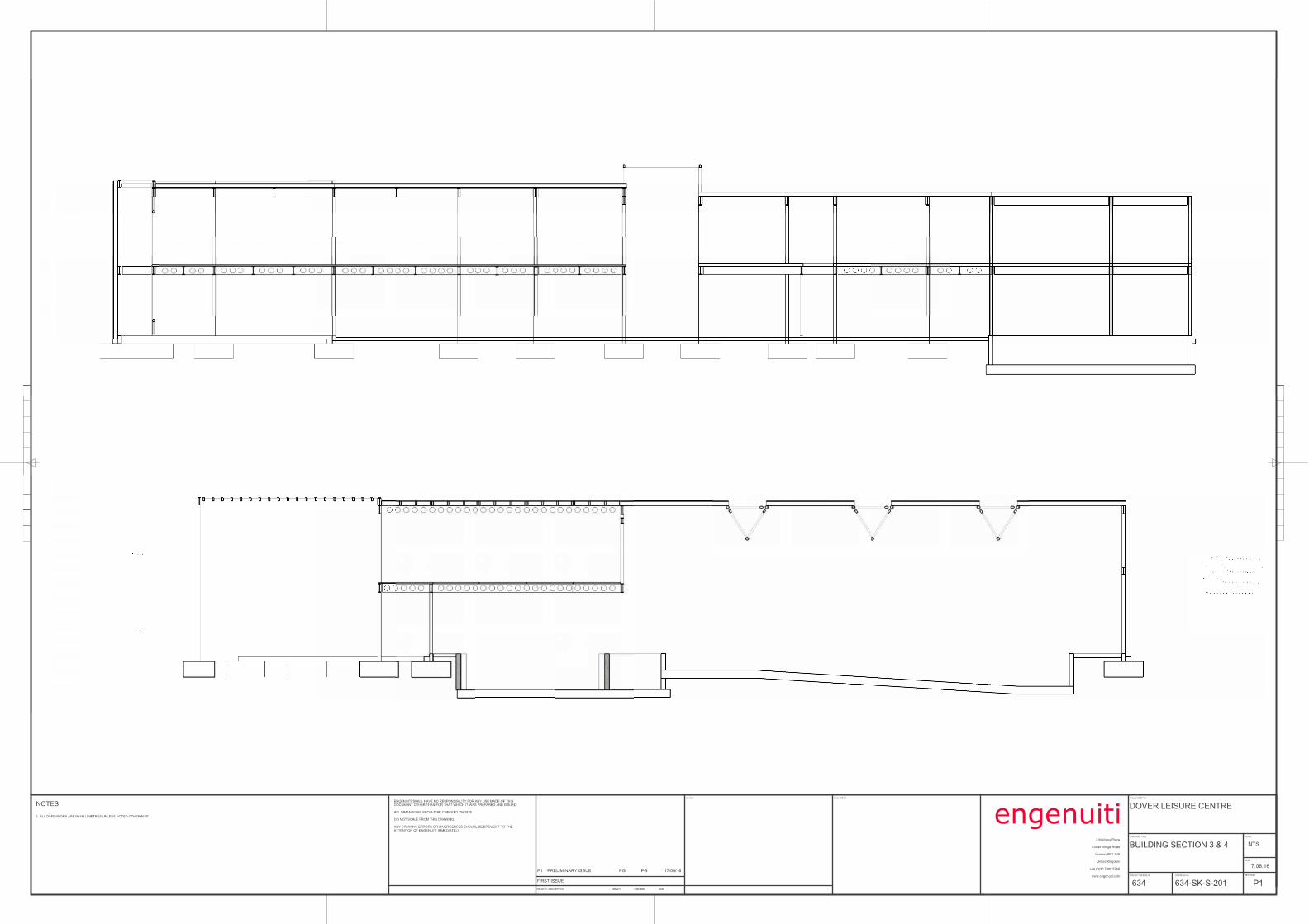
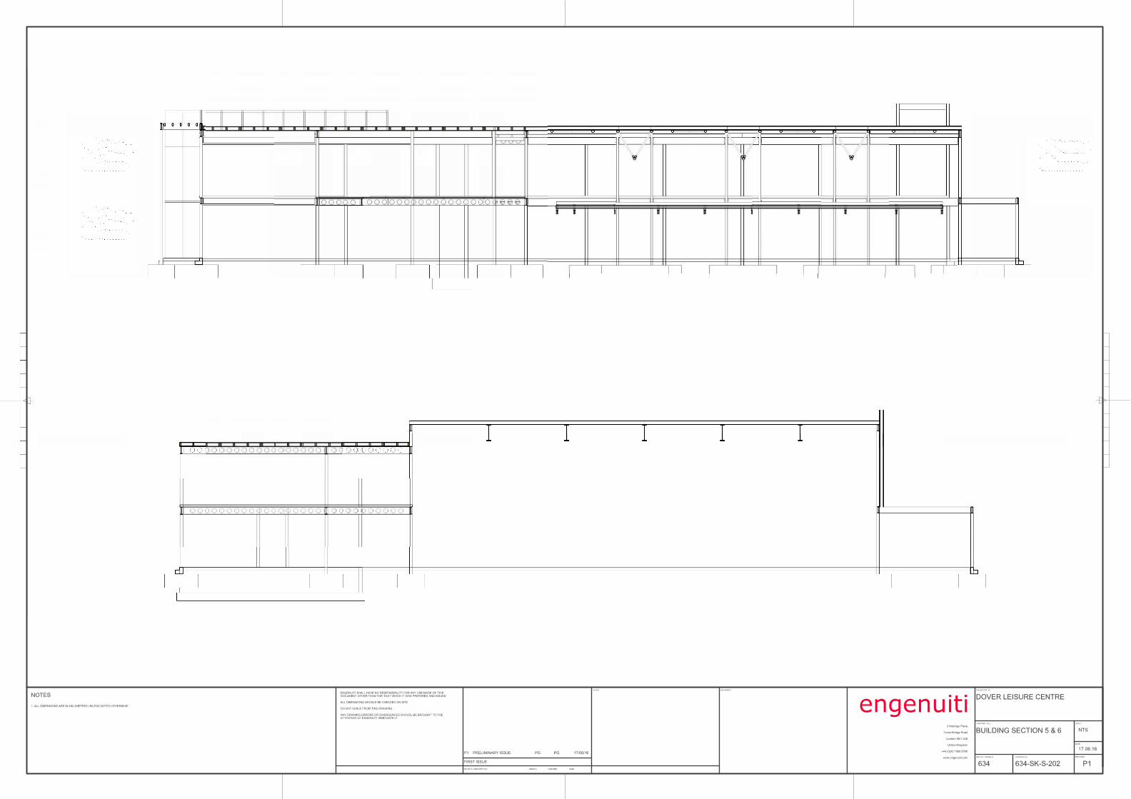
Dover Leisure Centre Structural & Civil Engineering RIBA Stage 2 Report engenuiti
Structural & Civil Engineering RIBA Stage 2 Report Date: 17 June 2016 Rev: 0 APPENDIX C
APPENDIX C LONG SPAN ROOF STUDIES
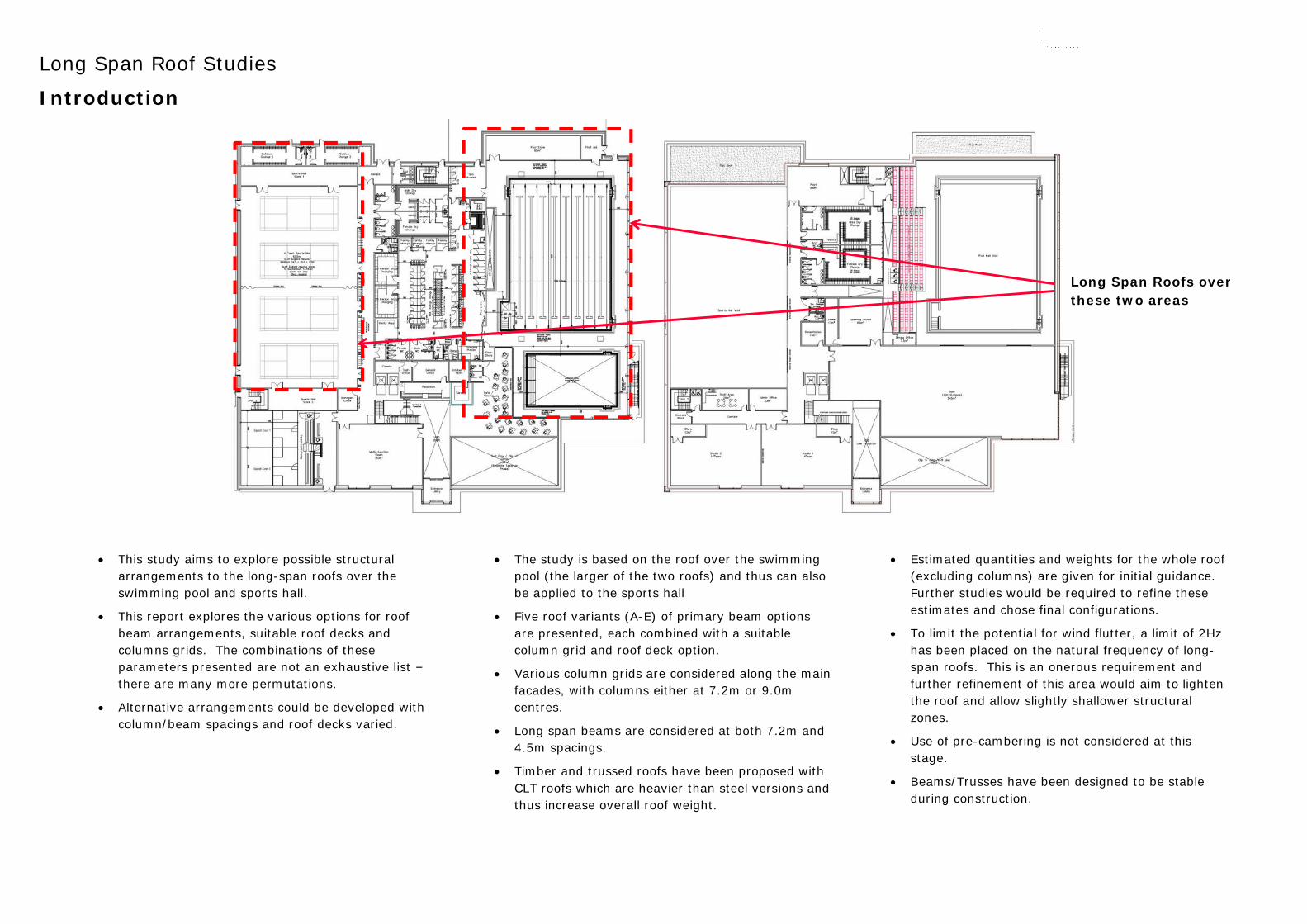
Long Span Roof Studies
Introduction
• This study aims to explore possible structural arrangements to the long-span roofs over the swimming pool and sports hall.
• This report explores the various options for roof beam arrangements, suitable roof decks and columns grids. The combinations of these parameters presented are not an exhaustive list – there are many more permutations.
• Alternative arrangements could be developed with column/beam spacings and roof decks varied.
• The study is based on the roof over the swimming pool (the larger of the two roofs) and thus can also be applied to the sports hall
• Five roof variants (A-E) of primary beam options are presented, each combined with a suitable column grid and roof deck option.
• Various column grids are considered along the main facades, with columns either at 7.2m or 9.0m centres.
• Long span beams are considered at both 7.2m and 4.5m spacings.
• Timber and trussed roofs have been proposed with CLT roofs which are heavier than steel versions and thus increase overall roof weight.
• Estimated quantities and weights for the whole roof (excluding columns) are given for initial guidance. Further studies would be required to refine these estimates and chose final configurations.
• To limit the potential for wind flutter, a limit of 2Hz has been placed on the natural frequency of long-span roofs. This is an onerous requirement and further refinement of this area would aim to lighten the roof and allow slightly shallower structural zones.
• Use of pre-cambering is not considered at this stage.
• Beams/Trusses have been designed to be stable during construction.
Long Span Roofs over these two areas
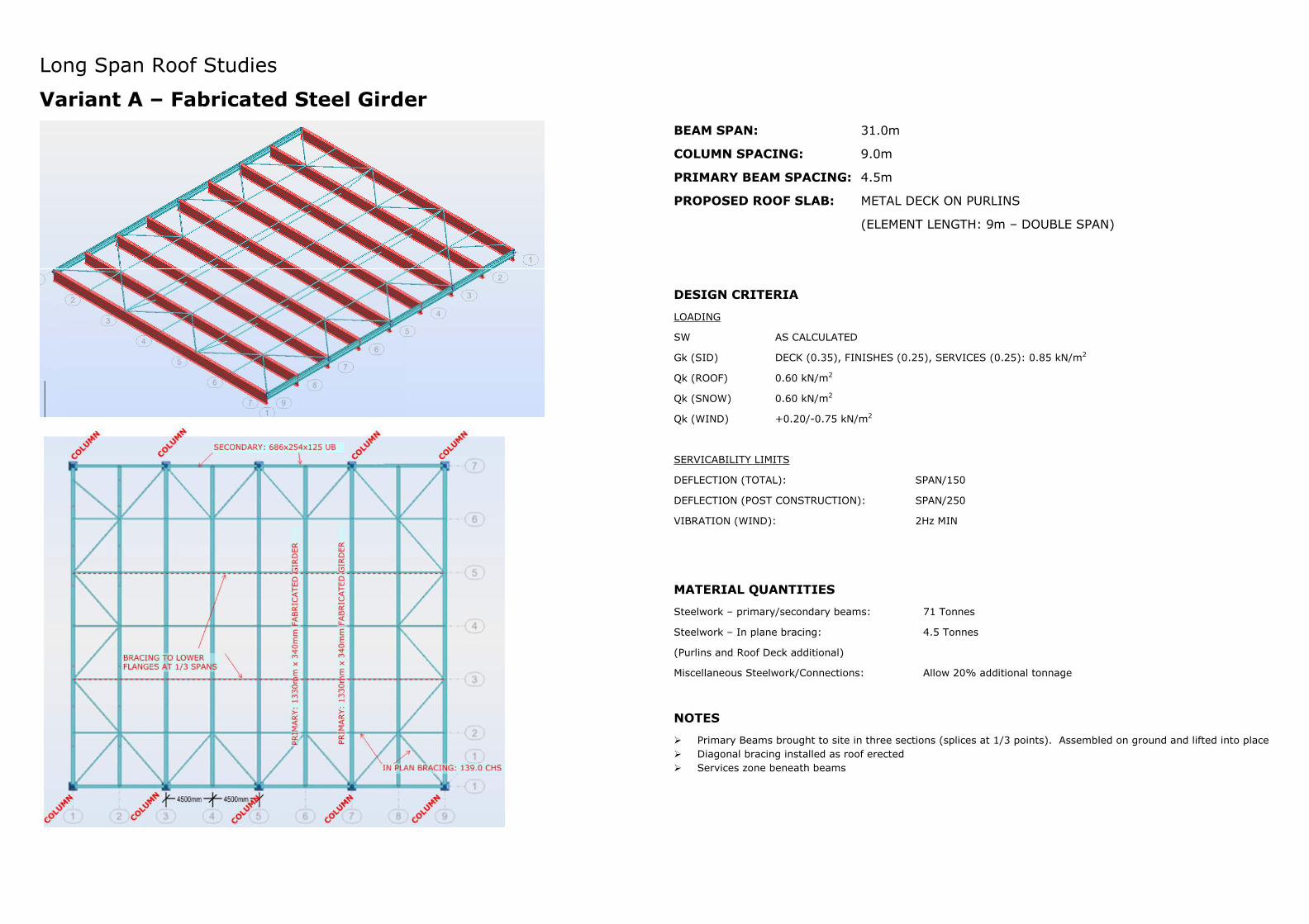
Long Span Roof Studies
Variant A – Fabricated Steel Girder
BEAM SPAN: 31.0m
COLUMN SPACING: 9.0m
PRIMARY BEAM SPACING: 4.5m
PROPOSED ROOF SLAB: METAL DECK ON PURLINS
(ELEMENT LENGTH: 9m – DOUBLE SPAN)
DESIGN CRITERIA
LOADING
SW AS CALCULATED
Gk (SID) DECK (0.35), FINISHES (0.25), SERVICES (0.25): 0.85 kN/m2
Qk (ROOF) 0.60 kN/m2
Qk (SNOW) 0.60 kN/m2
Qk (WIND) +0.20/-0.75 kN/m2
SERVICABILITY LIMITS
DEFLECTION (TOTAL): SPAN/150
DEFLECTION (POST CONSTRUCTION): SPAN/250
VIBRATION (WIND): 2Hz MIN
MATERIAL QUANTITIES
Steelwork – primary/secondary beams: 71 Tonnes
Steelwork – In plane bracing: 4.5 Tonnes
(Purlins and Roof Deck additional)
Miscellaneous Steelwork/Connections: Allow 20% additional tonnage
NOTES
� Primary Beams brought to site in three sections (splices at 1/3 points). Assembled on ground and lifted into place
� Diagonal bracing installed as roof erected
� Services zone beneath beams
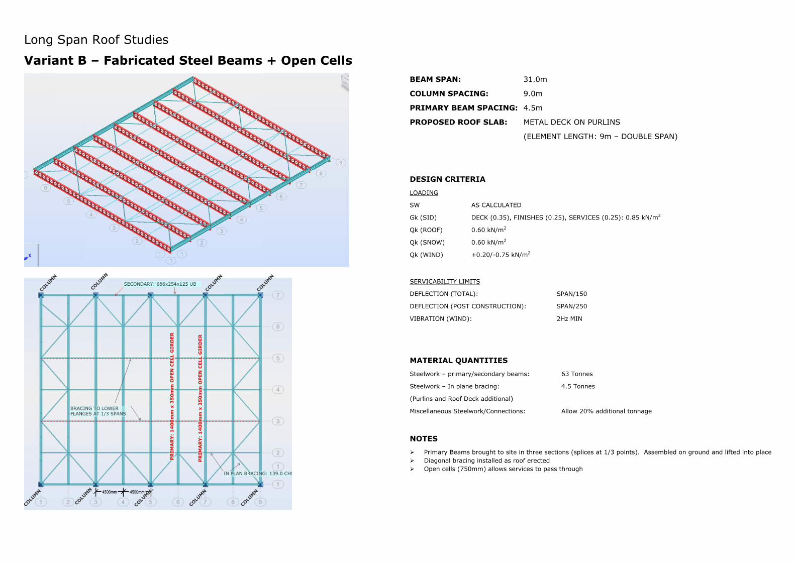
Long Span Roof Studies
Variant B – Fabricated Steel Beams + Open Cells
BEAM SPAN: 31.0m
COLUMN SPACING: 9.0m
PRIMARY BEAM SPACING: 4.5m
PROPOSED ROOF SLAB: METAL DECK ON PURLINS
(ELEMENT LENGTH: 9m – DOUBLE SPAN)
DESIGN CRITERIA
LOADING
SW AS CALCULATED
Gk (SID) DECK (0.35), FINISHES (0.25), SERVICES (0.25): 0.85 kN/m2
Qk (ROOF) 0.60 kN/m2
Qk (SNOW) 0.60 kN/m2
Qk (WIND) +0.20/-0.75 kN/m2
SERVICABILITY LIMITS
DEFLECTION (TOTAL): SPAN/150
DEFLECTION (POST CONSTRUCTION): SPAN/250
VIBRATION (WIND): 2Hz MIN
MATERIAL QUANTITIES
Steelwork – primary/secondary beams: 63 Tonnes
Steelwork – In plane bracing: 4.5 Tonnes
(Purlins and Roof Deck additional)
Miscellaneous Steelwork/Connections: Allow 20% additional tonnage
NOTES
� Primary Beams brought to site in three sections (splices at 1/3 points). Assembled on ground and lifted into place
� Diagonal bracing installed as roof erected
� Open cells (750mm) allows services to pass through
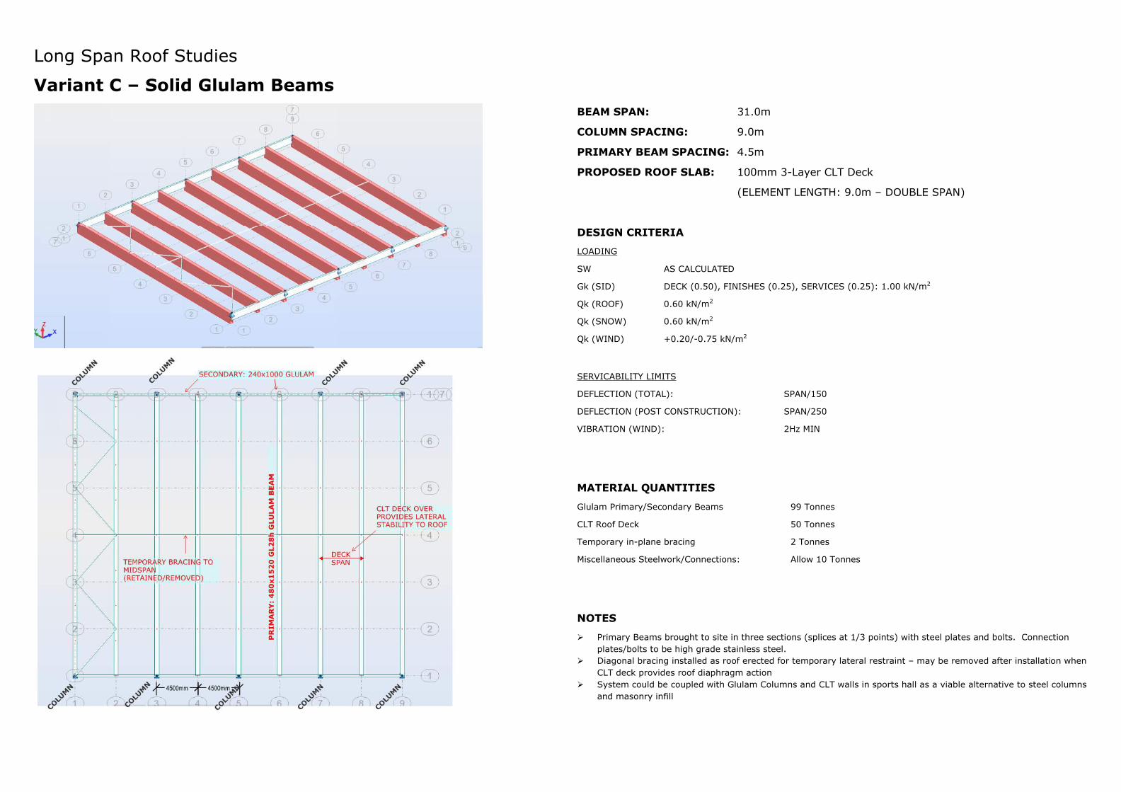
Long Span Roof Studies
Variant C – Solid Glulam Beams
BEAM SPAN: 31.0m
COLUMN SPACING: 9.0m
PRIMARY BEAM SPACING: 4.5m
PROPOSED ROOF SLAB: 100mm 3-Layer CLT Deck
(ELEMENT LENGTH: 9.0m – DOUBLE SPAN)
DESIGN CRITERIA
LOADING
SW AS CALCULATED
Gk (SID) DECK (0.50), FINISHES (0.25), SERVICES (0.25): 1.00 kN/m2
Qk (ROOF) 0.60 kN/m2
Qk (SNOW) 0.60 kN/m2
Qk (WIND) +0.20/-0.75 kN/m2
SERVICABILITY LIMITS
DEFLECTION (TOTAL): SPAN/150
DEFLECTION (POST CONSTRUCTION): SPAN/250
VIBRATION (WIND): 2Hz MIN
MATERIAL QUANTITIES
Glulam Primary/Secondary Beams 99 Tonnes
CLT Roof Deck 50 Tonnes
Temporary in-plane bracing 2 Tonnes
Miscellaneous Steelwork/Connections: Allow 10 Tonnes
NOTES
� Primary Beams brought to site in three sections (splices at 1/3 points) with steel plates and bolts. Connection
plates/bolts to be high grade stainless steel.
� Diagonal bracing installed as roof erected for temporary lateral restraint – may be removed after installation when
CLT deck provides roof diaphragm action
� System could be coupled with Glulam Columns and CLT walls in sports hall as a viable alternative to steel columns
and masonry infill
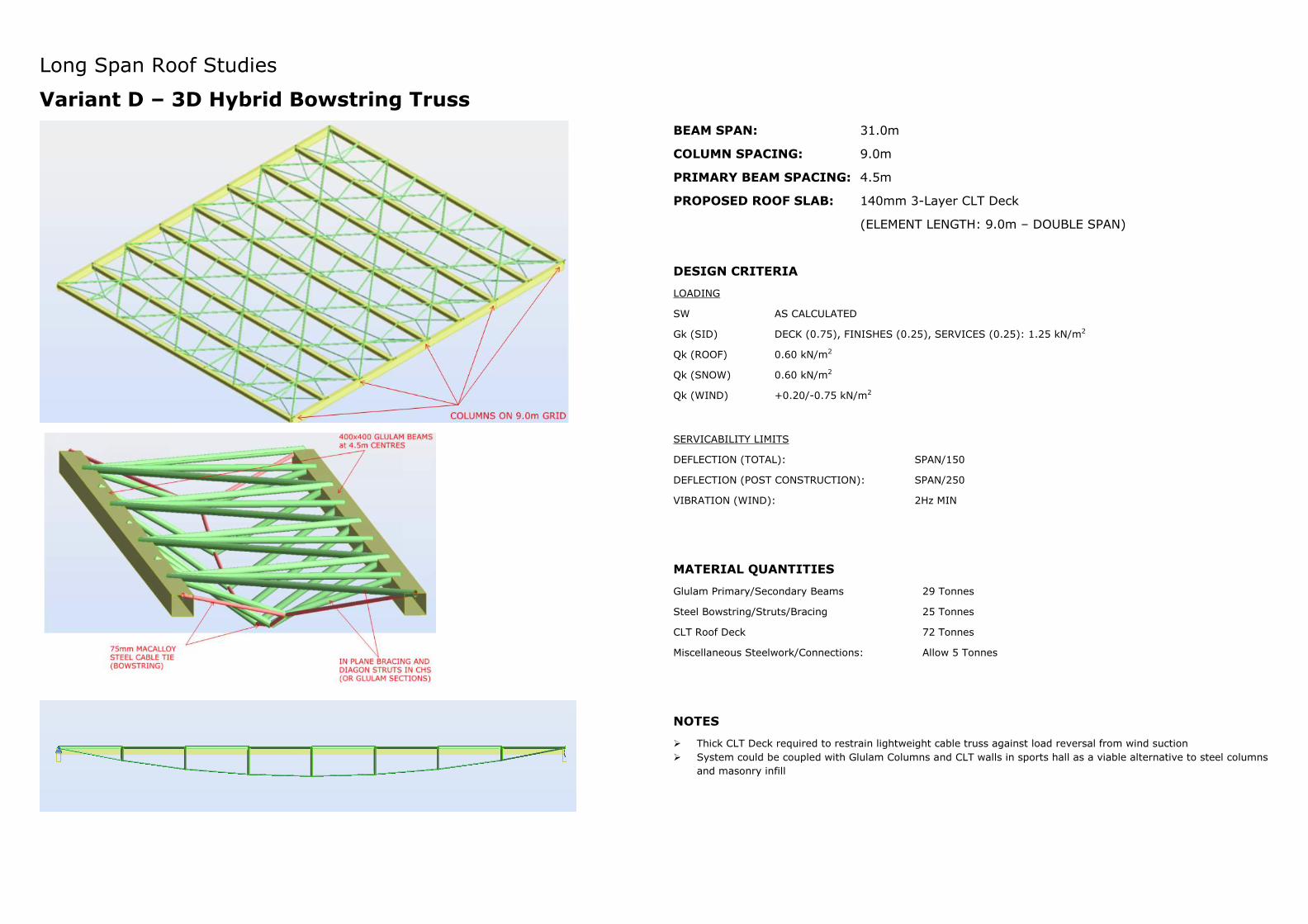
Long Span Roof Studies
Variant D – 3D Hybrid Bowstring Truss
BEAM SPAN: 31.0m
COLUMN SPACING: 9.0m
PRIMARY BEAM SPACING: 4.5m
PROPOSED ROOF SLAB: 140mm 3-Layer CLT Deck
(ELEMENT LENGTH: 9.0m – DOUBLE SPAN)
DESIGN CRITERIA
LOADING
SW AS CALCULATED
Gk (SID) DECK (0.75), FINISHES (0.25), SERVICES (0.25): 1.25 kN/m2
Qk (ROOF) 0.60 kN/m2
Qk (SNOW) 0.60 kN/m2
Qk (WIND) +0.20/-0.75 kN/m2
SERVICABILITY LIMITS
DEFLECTION (TOTAL): SPAN/150
DEFLECTION (POST CONSTRUCTION): SPAN/250
VIBRATION (WIND): 2Hz MIN
MATERIAL QUANTITIES
Glulam Primary/Secondary Beams 29 Tonnes
Steel Bowstring/Struts/Bracing 25 Tonnes
CLT Roof Deck 72 Tonnes
Miscellaneous Steelwork/Connections: Allow 5 Tonnes
NOTES
� Thick CLT Deck required to restrain lightweight cable truss against load reversal from wind suction
� System could be coupled with Glulam Columns and CLT walls in sports hall as a viable alternative to steel columns
and masonry infill
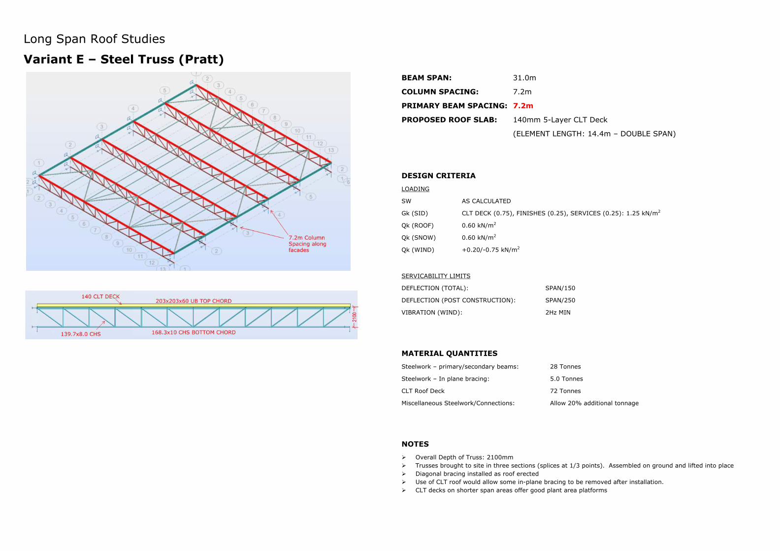
Long Span Roof Studies
Variant E – Steel Truss (Pratt)
BEAM SPAN: 31.0m
COLUMN SPACING: 7.2m
PRIMARY BEAM SPACING: 7.2m
PROPOSED ROOF SLAB: 140mm 5-Layer CLT Deck
(ELEMENT LENGTH: 14.4m – DOUBLE SPAN)
DESIGN CRITERIA
LOADING
SW AS CALCULATED
Gk (SID) CLT DECK (0.75), FINISHES (0.25), SERVICES (0.25): 1.25 kN/m2
Qk (ROOF) 0.60 kN/m2
Qk (SNOW) 0.60 kN/m2
Qk (WIND) +0.20/-0.75 kN/m2
SERVICABILITY LIMITS
DEFLECTION (TOTAL): SPAN/150
DEFLECTION (POST CONSTRUCTION): SPAN/250
VIBRATION (WIND): 2Hz MIN
MATERIAL QUANTITIES
Steelwork – primary/secondary beams: 28 Tonnes
Steelwork – In plane bracing: 5.0 Tonnes
CLT Roof Deck 72 Tonnes
Miscellaneous Steelwork/Connections: Allow 20% additional tonnage
NOTES
� Overall Depth of Truss: 2100mm
� Trusses brought to site in three sections (splices at 1/3 points). Assembled on ground and lifted into place
� Diagonal bracing installed as roof erected
� Use of CLT roof would allow some in-plane bracing to be removed after installation.
� CLT decks on shorter span areas offer good plant area platforms
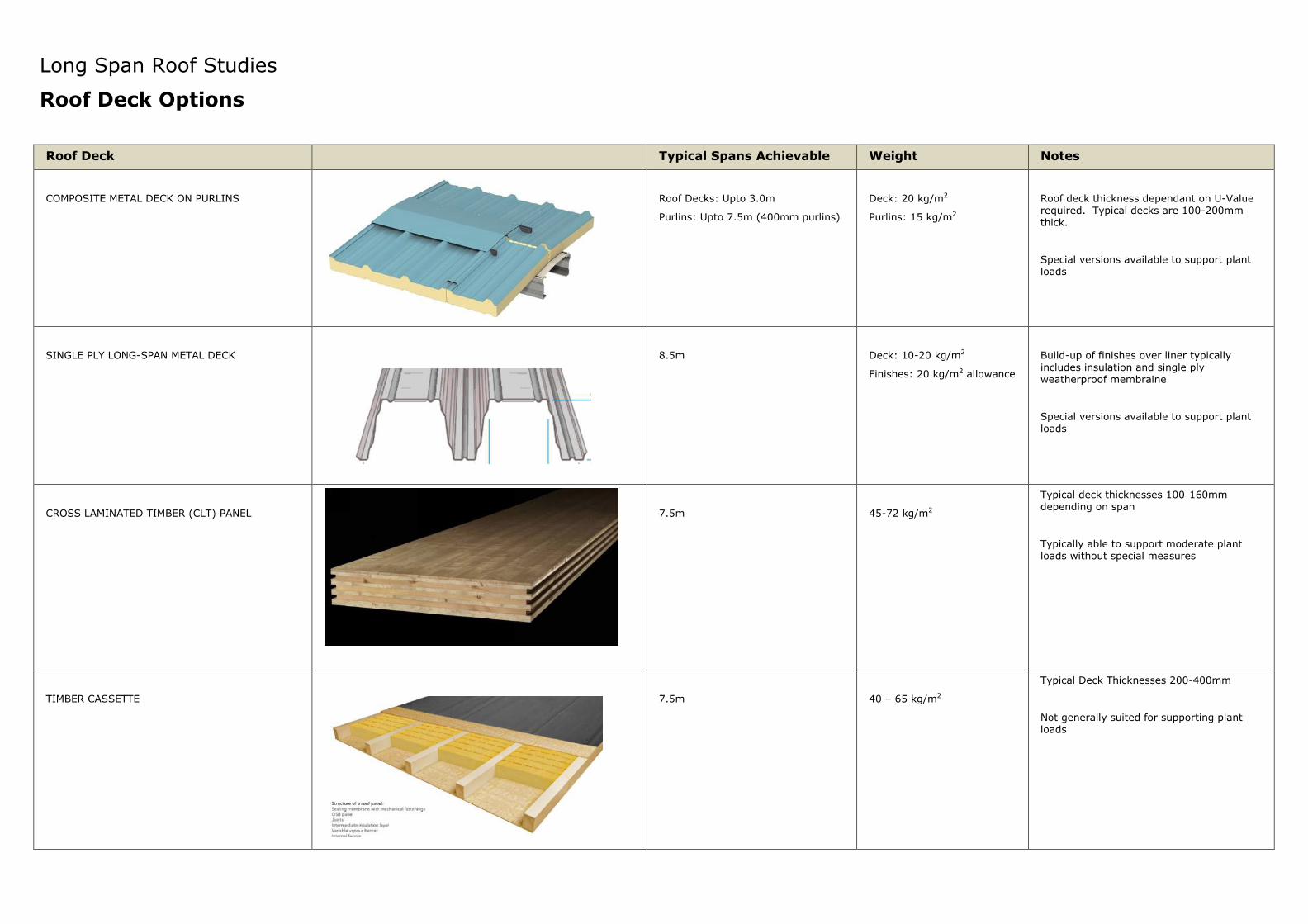
Long Span Roof Studies
Roof Deck Options
Roof Deck Typical Spans Achievable Weight Notes
COMPOSITE METAL DECK ON PURLINS
Roof Decks: Upto 3.0m
Purlins: Upto 7.5m (400mm purlins)
Deck: 20 kg/m2
Purlins: 15 kg/m2
Roof deck thickness dependant on U-Value
required. Typical decks are 100-200mm
thick.
Special versions available to support plant
loads
SINGLE PLY LONG-SPAN METAL DECK
8.5m
Deck: 10-20 kg/m2
Finishes: 20 kg/m2 allowance
Build-up of finishes over liner typically
includes insulation and single ply
weatherproof membraine
Special versions available to support plant
loads
CROSS LAMINATED TIMBER (CLT) PANEL
7.5m
45-72 kg/m2
Typical deck thicknesses 100-160mm
depending on span
Typically able to support moderate plant
loads without special measures
TIMBER CASSETTE
7.5m
40 – 65 kg/m2
Typical Deck Thicknesses 200-400mm
Not generally suited for supporting plant
loads