Embed Size (px)
Citation preview
Atas dos ArtigosProceedings (full papers)
5º CONGRESSO IBERO-LATINO-AMERICANO EM SEGURANÇA CONTRA INCÊNDIOS
5th IBERIAN-LATIN-AMERICAN CONGRESS ON FIRE SAFETY
15-17 /07/ 2019 - Porto, Portugal
5th IBERIAN-LATIN-AMERICAN CONGRESS ON FIRE SAFETY – CILASCI 5 Porto, Portugal, 15 - 17 July 2019
i

5th IBERIAN-LATIN-AMERICAN CONGRESS ON FIRE SAFETY – CILASCI 5 Porto, Portugal, 15 - 17 July 2019
ii
5th IBERIAN-LATIN-AMERICAN CONGRESS ON FIRE SAFETY – CILASCI 5 Porto, Portugal, 15 - 17 July 2019
iii
TITLE: Atas dos Artigos 5º Congresso IBERO-LATINO-AMERICANO EM SEGURANÇA CONTRA INCÊNDIOS Full Papers Proceedings 5th IBERIAN-LATIN-AMERICAN CONGRESS ON FIRE SAFETY PUBLISHER: ALBRASCI - Associação Luso-Brasileira para a Segurança Contra Incêndio ALBRASCI - Luso Brazilian Association for Fire Safety EDITORS: Paulo Piloto (IPB - DMA), Débora Ferreira (IPB - DMA), Elza Fonseca (ISEP - DEM), João Santos Baptista (FEUP-DEM), José Miguel Castro (FEUP – DEC), Luís Mesquita (IPB - DMA), Mário Vaz (FEUP-DEMec), Miguel Chichorro (FEUP – DEC), Rui Miranda Guedes (FEUP-DEMec) et al. BOOK COVER DESIGN: Soraia Maduro – Instituto Politécnico de Bragança INTERNET WEB PAGE: Pedro Oliveira – Instituto Politécnico de Bragança EDITION: 1ª, Julho de 2019 ISBN: 978-989-97210-3-6 IMPRINT: Tipografia Artegráfica Brigantina NOTE: No part of this work may be reproduced without the written permission of the authors and the publisher.
5th IBERIAN-LATIN-AMERICAN CONGRESS ON FIRE SAFETY – CILASCI 5 Porto, Portugal, 15 - 17 July 2019
iv
PREFACE
The Iberian-Latin American Congress on Fire Safety (CILASCI) is held once every two years, with the aim of disseminating scientific and technical knowledge in the field of fire safety, integrating different players involved in this area of knowledge. The first edition of the Iberian-Latin American Congress on Fire Safety (CILASCI 1), was held in Natal (Brazil) between 10-12 March 2011. The second congress (CILASCI 2) was held in Coimbra (Portugal), between May 29 and June 1, 2013. The 3rd and 4th editions took place on the South American continent. The third congress (CILASCI 3) was held in Porto Alegre (Brazil) from November 3 to 6, 2015, while the fourth congress (CILASCI 4) was held in Recife (Brazil) from 9 to 11 October 2017. The CILASCI 5 will take place in the city of Porto (Portugal) from 15 to 17 July 2019, and presents 5 invited lectures and 78 manuscripts (full papers) from researchers around the world (Algeria, Australia, Belgium, Brazil, China, Czech Republic, France, Hong Kong, Italy, Mozambique, Portugal, Spain, United Kingdom and United States). the 5th Iberian-Latin-American congress on fire safety reflects the new developments achieved on active and passive fire protection, on evacuation and human behaviour under fire, on computational modelling of structures and materials under fire, on explosion and risk management, on architectural issues for fire safety in buildings, on fire dynamics, on the experimental analysis of materials and structures under fire, on fires in special buildings and spaces, on fire-fighting operations and equipments, and on the behaviour of structures and materials under fire. The Fire Safety is reaching new developments as a result of new research, development and innovation around the world, based on the excellence level of the research, the support of new skilled professionals and due to the existence of advanced training programmes in fire science technology. This development will increase the safety level of people, buildings, and products, but also is going to produce an impact in the economy of each country, with a positive impact on society. The organizing committee believe that this congress will address to our delegates a wide forum of discussion about the recent developments in Fire Safety, promoting the exchange of ideas and international cooperation. The organizing Committee would like to thanks to all authors and delegates. On the behalf of the Organizing Committe Paulo A. G. Piloto
5th IBERIAN-LATIN-AMERICAN CONGRESS ON FIRE SAFETY – CILASCI 5 Porto, Portugal, 15 - 17 July 2019
v
ORGANIZING COMMITTEE
Paulo Piloto, Insituto Politécnico de Bragança - DMA Débora Ferreira, Insituto Politécnico de Bragança - DMA Elza Fonseca, Instituto Politécnico do Porto- ISEP - DEM
João Santos Baptista, Faculdade de Engenharia da Universidade do Porto - DEM José Miguel Castro, Faculdade de Engenharia da Universidade do Porto – DEC
Luís Mesquita, Insituto Politécnico de Bragança - DMA Mário Vaz, Faculdade de Engenharia da Universidade do Porto -DEMec
Miguel Chichorro, Faculdade de Engenharia da Universidade do Porto – DEC Rui Miranda Guedes, Faculdade de Engenharia da Universidade do Porto -DEMec
5th IBERIAN-LATIN-AMERICAN CONGRESS ON FIRE SAFETY – CILASCI 5 Porto, Portugal, 15 - 17 July 2019
vi
SCIENTIFIC COMMITTEE
Aldina Maria Santiago – Universidade de Coimbra – Portugal Ana Belén Ramos Gavilán - Universidade de Salamanca – Espanha
Ângela Gaio Graeff – Universidade Federal do Rio Grande do Sul – UFRGS - Brasil André Teles – Corpo de Bombeiros Militar do Distrito Federal – CBMDF - Brasil
António Moura Correia – Instituto Politécnico de Coimbra – Portugal Armando L. Moreno Júnior – Universidade Estadual de Campinas – UNICAMP - Brasil
Bernardo Tutikian – Universidade do Vale dos Sinos – Brasil Carla Neves Costa – Universidade Estadual de Campinas – UNICAMP - Brasi
Carlos Balsa - – Instituto Politécnico de Bragança - Portugal Carlos Pina dos Santos – Laboratório Nacional de Engenharia Civil – Portugal
Cristina Calmeiro dos Santos – Instituto Politécnico de Castelo Branco – Portugal Daniel Alvear Portilla - Universidade de Santander - Espanha
Dayse Cavalcanti Duarte – Universidade Federal de Pernambuco – Brasil Débora Rodrigues de Sousa Macanjo Ferreira - Instituto Politécnico de Bragança – Portugal
Domingues Xavier Viegas – Universidade de Coimbra - UC - Portugal Edna Moura Pinto – Universidade Federal do Rio Grande do Norte – Brasil
Elza Maria Morais Fonseca - Instituto Superior de Engenharia do Porto – Portugal Fabio Martin Rocha – Universidade de São Paulo – USP - Brasil
Francisco Carlos Rodrigues – Universidade Federal de Minas Gerais – Brasil Gabriela B. de M. Lins de Albuquerque– Universidade de São Paulo – USP - Brasil
George Cajaty Braga – Corpo de Bombeiros Militar do Distrito Federal – CBMDF - Brasil Geraldine Charreau – Instituto Nacional de Tecnologia Industrial – Argentina
João Santos Baptista - Universidade do Porto – FEUP - Portugal João Godinho Viegas – Laboratório Nacional de Engenharia Civil – Portugal
João Paulo Correia Rodrigues – Universidade de Coimbra – Portugal (Coord.) João Ramôa Correia - Universidade de Lisboa – IST – Portugal
Jorge Gil Saraiva – Laboratório Nacional de Engenharia Civil - Portugal Jorge Munaiar Neto – Escola de Engenharia de São Carlos da Univ. de São Paulo – Brasil
Jorge Saul Suaznabar Velarde - IASU - Bolívia José Carlos Lopes Ribeiro – Universidade Federal de Viçosa - Brasil
José Carlos Miranda Góis – Universidade de Coimbra - Portugal José Jéferson do Rêgo Silva – Universidade Federal de Pernambuco – Brasil
Jose Luis Torero - Universidade de Maryland - Austrália José Miguel Castro - Universidade do Porto – FEUP - Portugal
Larissa Kirchhof – Universidade Federal de Santa Maria – Brasil Lino Forte Marques – Universidade de Coimbra – Portugal
Luiz Carlos Pinto da Silva Filho– Universidade Federal do Rio Grande do Sul – UFRGS Luís Mesquita – Instituto Politécnico de Bragança – Portugal
Manuel Romero Garcia – Universidade Politécnica de Valencia – Espanha Mariano Lázaro Urrutia - Universidade de Santander - Espanha
Mário Augusto Pires Vaz - Universidade do Porto – FEUP - Portugal Miguel Chichorro Gonçalves – Universidade do Porto – FEUP - Portugal
Nuno Filipe Borges Lopes – Universidade de Aveiro – Portugal Orlando V. Abreu Menéndez - Universidade de Santander – Espanha
5th IBERIAN-LATIN-AMERICAN CONGRESS ON FIRE SAFETY – CILASCI 5 Porto, Portugal, 15 - 17 July 2019
vii
Paulo A. G. Piloto – Instituto Politécnico de Bragança - Portugal Paulo Jorge M. F. Vila Real – Universidade de Aveiro – Portugal
Poliana Dias de Moraes – Universidade Federal de Santa Catarina - Brasil Ricardo Azoubel Silveira – Universidade Federal de Ouro Preto – Brasil
Ricardo Cruz Hernandez – Universidade Industrial de Santander – Colômbia Ricardo Fakury – Universidade Federal de Minas Gerais - Brasil
Rodrigo Barreto Caldas – Universidade Federal de Minas Gerais – Brasil Rogério Antocheves – Universidade Federal de Santa Maria – Brasil
Ronaldo Rigobello - Universidade Tecnológica Federal do Paraná – Brasil Rosária Ono – Faculdade de Arquitetura da Universidade de São Paulo – Brasil
Rui Faria – Universidade do Porto FEUP – Portugal Rui Miranda Guedes - Universidade do Porto FEUP – Portugal
Saulo Almeida – Universidade Estadual de Campinas – UNICAMP - Brasil Tiago Ancelmo de Carvalho Pires – Universidade Federal de Pernambuco – Brasil
Valdir Pignatta e Silva – Escola Politécnica da Universidade de São Paulo – Brasil (Coord.) Wolfram Jahn – Pontifícia Universidade Católica do Chile – Chile
5th IBERIAN-LATIN-AMERICAN CONGRESS ON FIRE SAFETY – CILASCI 5 Porto, Portugal, 15 - 17 July 2019
viii
INDEX PREFACE ............................................................................................................................................................................. iv
ORGANIZING COMMITTEE .................................................................................................................................................. v
SCIENTIFIC COMMITTEE .................................................................................................................................................... vi
INVITED LECTURES .............................................................................................................................................................1
EMERGENCY EXITS IN HIGH-RISE BUILDINGS .................................................................................................................3
A NOVA GERAÇÃO DAS PARTES 1-2 (VERIFICAÇÃO DA RESISTÊNCIA AO FOGO) DOS EUROCÓDIGOS ESTRUTURAIS 1, 3 E 4 ....................................................................................................................................................... 13
CHARACTERIZATION OF THE FIRE REACTION OF MATERIALS .................................................................................... 31
CONTROLO DE FUMO EM COMPARTIMENTOS: SIMULAÇÃO E EXPERIMENTAÇÃO .................................................. 41
SESSION S1A: ACTIVE AND PASSIVE FIRE PROTECTION ............................................................................................ 69
ESTIMATIVA DA POTÊNCIA CALORÍFICA LIBERTADA NO INCÊNDIO OCORRIDO NO TÚNEL DO MARÃO EM 2017-06-11 ......................................................................................................................................................................................... 71
A IMPORTÂNCIA DOS SISTEMAS DE PROTEÇÃO QUE INDEPENDEM DO USUÁRIO PARA EDIFICAÇÕES OCUPADAS POR PESSOAS COM DIFICULDADE DE MOBILIDADE AUTÔNOMA EM CASO DE INCÊNDIO ...................................... 81
PROPIEDADES TÉRMICAS DE LADRILLOS CERÁMICOS CON ADICION DE PRODUCTOS DE RECICLADO: REVISIÓN DE ESTUDIOS ..................................................................................................................................................................... 89
INTUMESCENT COATINGS FOR THE PROTECTION OF STRUCTURAL STEEL IN CELLULOSIC FIRES – WATER BORNE VS SOLVENT BORNE ........................................................................................................................................... 99
SYNTHESIS OF SILICA NANOPARTICLES TO ENHANCE THE FIRE RESISTANCE OF CEMENT MORTARS ............. 113
SESSION S1B: EVACUATION AND HUMAN BEHAVIOUR UNDER FIRE ...................................................................... 123
EVACUAÇÃO EMERGENCIAL DE EDIFICAÇÕES HOSPITALARES ............................................................................... 125
A INFLUÊNCIA DE DIFERENTES ÂNGULOS DE FUSÃO ENTRE FLUXOS DE PEDESTRES NO TEMPO DE EVACUAÇÃO ........................................................................................................................................................................................... 133
ESCADAS E RAMPAS EM SAÍDAS DE EMERGÊNCIA E O TEMPO DE EVACUAÇÃO EM EDIFICAÇÃO ESCOLAR ... 145
MÉTODO PARA COLETA DE TEMPOS E TRAJETOS EM ESCADAS PARA A OBTENÇÃO DE VELOCIDADE DE CAMINHAMENTO DE CRIANÇAS EM SIMULADOS DE ABANDONO ............................................................................. 155
SESSION S2A: COMPUTATIONAL MODELLING OF STRUCTURES AND MATERIALS UNDER FIRE ........................ 167
NON-LOADBEARING LIGHT STEEL FRAMING WALLS UNDER FIRE ............................................................................ 169
NUMERICAL SIMULATION OF COMPOSITE SLABS WITH STEEL DECK UNDER FIRE CONDITIONS ........................ 187
MODELO NUMÉRICO TRIDIMENSIONAL PARA A VERIFICAÇÃO DO COMPORTAMENTO DE VIGAS DE CONCRETO ARMADO EM SITUAÇÃO DE INCÊNDIO .......................................................................................................................... 203
5th IBERIAN-LATIN-AMERICAN CONGRESS ON FIRE SAFETY – CILASCI 5 Porto, Portugal, 15 - 17 July 2019
187
NUMERICAL SIMULATION OF COMPOSITE SLABS WITH STEEL DECK UNDER FIRE CONDITIONS
Carlos Balsa 21F
* Professor IPB Bragança
Fernando F. RibeiroStudent UTFPR Brazil
Paulo A. G. Piloto Professor IPB Bragança
Ronaldo Rigobello Professor UTFPR Brazil
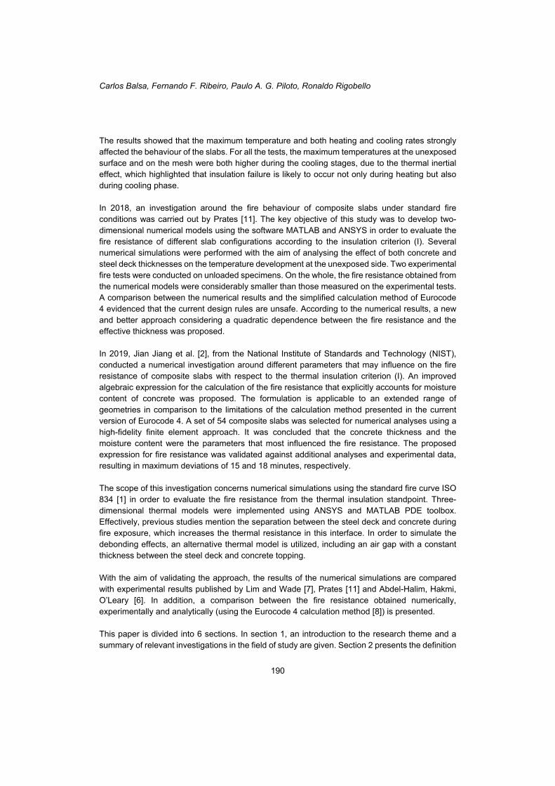
Keywords: Composite slabs; Fire resistance; Insulation criterion; Numerical simulation. 1. INTRODUCTION A composite steel-concrete slab consists of a concrete topping cast on the top of a profiled steel deck. Normally, the concrete is reinforced with an anti-crack mesh positioned on the upper part and individual reinforcing bars placed within the ribs, see Figure 1. The steel deck acts as a permanent formwork and the composite action between the steel and concrete is generally achieved by indentations or embossments in the steel deck. Due to the reinforcement provided by the steel deck, composite slabs are generally slenderer and more efficient than flat concrete slabs because require less additional reinforcement and less concrete as well. The reduction of the construction time, simplicity of installation and reduction/elimination of struts are other advantages of composite slabs that should be highlighted. Since the decade of 1980, a significant increase in the use of composite slabs with steel deck has taken place in Europe. The most popular types of shapes of the profiled steel deck are trapezoidal and re-entrant. Owing to the ease of casting concrete, slabs with trapezoidal steel deck are more popular than re-entrant ones. The overall depth of composite slabs usually varies between 100 and 170 mm, and the steel deck thickness between 0.7 and 1.2 mm. Generally, with the objective
*Autor correspondente – Dep. de Matemática, Insituto Politécnico de Bragança. Campus Santa Apolónia, 5300-253 Bragança.
Telef.: +351 273 303090, Fax: +351 273 313051, E-mail: [email protected]
Carlos Balsa, Fernando F. Ribeiro, Paulo A. G. Piloto, Ronaldo Rigobello
188
to prevent corrosion and increase durability, the steel deck is protected with a zinc layer on both faces.
Figure 1: Typical layout of a composite slab with trapezoidal steel deck. The steel deck may be directly exposed to accidental fire conditions. Composite slabs have to meet fire-safety requirements in accordance to standards and regulations. Normally, this structural element is rated on the basis of standard fire tests using the standard fire curve ISO 834 [1]. The fire resistance should be determined according to three different criteria, namely Load Bearing (R), Integrity (E) and Insulation (I). The profiled geometry of the steel deck and the presence of the ribs in composite slabs create an orthotropic profile, resulting in complex thermal gradients hence presenting challenges in numerical modelling [2]. In recent years, several studies have been conducted in order to investigate the fire behaviour of this structural element. In 1983, recognizing the need for a calculation method, the European Convention for Constructional Steelwork (ECCS) [3] published the first instructions applied to the design of composite slabs with profiled steel deck under standard fire conditions. This document introduced simple calculation rules, which were based on the results of fire tests performed on different European laboratories, enabling the fire resistance of composite slabs to be quickly calculated. According to this technical note, for properly designed slabs, the explicit fire design is not required to achieve a fire resistance of 30 minutes or less. In addition, it establishes that if the insulation criterion for fire resistance is fulfilled, then the integrity criterion is also fulfilled. At this time, the knowledge around the fire behaviour of composite slabs was incomplete and conservative assumptions were adopted, resulting in uneconomical solutions. In 1991, Hamerlinck [4] conducted a numerical and experimental study regarding the thermal and mechanical behaviour of reinforced composite slabs under fire conditions. Both numerical models were experimentally validated with loaded and unloaded tests. Due to the melting of the zinc layer and surface blackening, the resulting emissivity of galvanized steel decks was calculated as temperature dependent. The testing programme took into consideration the most important parameters for fire resistance and a new computer program was developed, enabling simulations at low computational cost (low time processing). It was concluded that the developed two-dimensional model provided satisfactory results, although not including three-dimensional thermal effects.
Numerical simulation of composite slabs with steel deck under fire conditions
189
In 1998, an investigation was carried out by Both [5] with the main objective of introducing easy to handle calculation rules as well as providing more insight on the fire behaviour and failure mechanisms mainly of continuous composite slabs. The numerical models were validated against the results of experimental tests performed by the author and other researchers. The three-dimensional effects near internal supports, concrete cracking and the melting of the zinc layer of the steel deck were considered. Finally, a parameter study was performed and simple calculation rules were derived from the results using standard regression techniques. It was concluded that the thermal model was able to describe the two and three-dimensional heat flow in composite slabs during fire exposure and the assessment rules for the fire resistance given in Eurocode 4 at that time could be considerably improved, among other conclusions. In 1999, Abdel-Halim, Hakmi and O’Leary [6] conducted a study with the main goal of providing data about the performance of fire exposed composite slabs adopting a model fire test facility. Two different specimens, one with and another without additional longitudinal reinforcement bars were tested using the standard fire ISO 834 in the University of Salford, UK. Thereupon, the investigation focused on the analysis of the effect of additional bars on the fire resistance as well as on the comparison between the fire resistance of the samples with respect to integrity and insulation criteria. It was concluded that the specimen without reinforcement bars presented a lower rate of temperature rise at the unexposed surface in comparison to the reinforced specimen and consequently, a higher fire resistance in both insulation and integrity criteria. In 2002, Lim and Wade [7] performed fire tests on six large-scale concrete slabs, comprising three reinforced concrete flat slabs and three composite steel-concrete slabs. The main objective of the tests was to analyse the fire behaviour of unrestrained simply supported slabs in a controlled furnace. The slabs were subjected to a live load and standard fire conditions during three hours. All the slabs resisted the full duration of the tests without collapsing, despite presenting extensive surface cracking on the unexposed surface and large deflections (up to 270 mm). In general, the measured fire resistance was higher than the predictions from normative recommendations. The results evidenced the important effect of membrane action on preserving the structural stability of the slabs under fire conditions. In 2005, the European Commission for Standardization (CEN), published design rules for composite steel and concrete structures under fire conditions, EN 1994-1-2 [8]. This standard determines that if a composite slab with profiled steel deck, with or without additional reinforcement, is properly designed according to EN 1994-1-1 [9], the fire resistance (R) is at least 30 minutes. In addition, it also states that the integrity criterion (E) is always verified for composite slabs with steel deck. Regarding the insulation criterion (I), the Annex D presents a simple calculation method, which depends on the geometry of the steel deck, the thickness of concrete above the steel deck and the view factor of the upper flange. In 2011, Guo and Bailey [10] executed an experimental investigation with the aim of providing more insight on the behaviour of composite slabs during heating and cooling phases of fire. Nine equal specimens were tested: two of them at room temperature and the others at three different fire scenarios, which were controlled by burners and fans within the furnace. The specimens were loaded with representative values found in practice in order to investigate the structural behaviour.
Carlos Balsa, Fernando F. Ribeiro, Paulo A. G. Piloto, Ronaldo Rigobello
190
The results showed that the maximum temperature and both heating and cooling rates strongly affected the behaviour of the slabs. For all the tests, the maximum temperatures at the unexposed surface and on the mesh were both higher during the cooling stages, due to the thermal inertial effect, which highlighted that insulation failure is likely to occur not only during heating but also during cooling phase. In 2018, an investigation around the fire behaviour of composite slabs under standard fire conditions was carried out by Prates [11]. The key objective of this study was to develop two-dimensional numerical models using the software MATLAB and ANSYS in order to evaluate the fire resistance of different slab configurations according to the insulation criterion (I). Several numerical simulations were performed with the aim of analysing the effect of both concrete and steel deck thicknesses on the temperature development at the unexposed side. Two experimental fire tests were conducted on unloaded specimens. On the whole, the fire resistance obtained from the numerical models were considerably smaller than those measured on the experimental tests. A comparison between the numerical results and the simplified calculation method of Eurocode 4 evidenced that the current design rules are unsafe. According to the numerical results, a new and better approach considering a quadratic dependence between the fire resistance and the effective thickness was proposed. In 2019, Jian Jiang et al. [2], from the National Institute of Standards and Technology (NIST), conducted a numerical investigation around different parameters that may influence on the fire resistance of composite slabs with respect to the thermal insulation criterion (I). An improved algebraic expression for the calculation of the fire resistance that explicitly accounts for moisture content of concrete was proposed. The formulation is applicable to an extended range of geometries in comparison to the limitations of the calculation method presented in the current version of Eurocode 4. A set of 54 composite slabs was selected for numerical analyses using a high-fidelity finite element approach. It was concluded that the concrete thickness and the moisture content were the parameters that most influenced the fire resistance. The proposed expression for fire resistance was validated against additional analyses and experimental data, resulting in maximum deviations of 15 and 18 minutes, respectively. The scope of this investigation concerns numerical simulations using the standard fire curve ISO 834 [1] in order to evaluate the fire resistance from the thermal insulation standpoint. Three-dimensional thermal models were implemented using ANSYS and MATLAB PDE toolbox. Effectively, previous studies mention the separation between the steel deck and concrete during fire exposure, which increases the thermal resistance in this interface. In order to simulate the debonding effects, an alternative thermal model is utilized, including an air gap with a constant thickness between the steel deck and concrete topping. With the aim of validating the approach, the results of the numerical simulations are compared with experimental results published by Lim and Wade [7], Prates [11] and Abdel-Halim, Hakmi, O’Leary [6]. In addition, a comparison between the fire resistance obtained numerically, experimentally and analytically (using the Eurocode 4 calculation method [8]) is presented. This paper is divided into 6 sections. In section 1, an introduction to the research theme and a summary of relevant investigations in the field of study are given. Section 2 presents the definition
Numerical simulation of composite slabs with steel deck under fire conditions
191
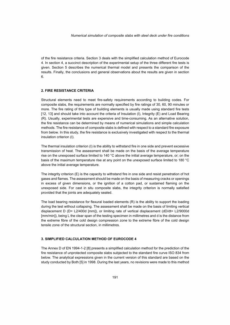
of the fire resistance criteria. Section 3 deals with the simplified calculation method of Eurocode 4. In section 4, a succinct description of the experimental setup of the three different fire tests is given. Section 5 describes the numerical thermal model and presents the comparison of the results. Finally, the conclusions and general observations about the results are given in section 6. 2. FIRE RESISTANCE CRITERIA Structural elements need to meet fire-safety requirements according to building codes. For composite slabs, the requirements are normally specified by fire ratings of 30, 60, 90 minutes or more. The fire rating of this type of building elements is usually made using standard fire tests [12, 13] and should take into account the criteria of Insulation (I), Integrity (E) and Load Bearing (R). Usually, experimental tests are expensive and time-consuming. As an alternative solution, the fire resistance can be determined by means of numerical simulations and simple calculation methods. The fire resistance of composite slabs is defined with respect to a standard fire exposure from below. In this study, the fire resistance is exclusively investigated with respect to the thermal insulation criterion (I). The thermal insulation criterion (I) is the ability to withstand fire in one side and prevent excessive transmission of heat. The assessment shall be made on the basis of the average temperature rise on the unexposed surface limited to 140 °C above the initial average temperature, or; on the basis of the maximum temperature rise at any point on the unexposed surface limited to 180 °C above the initial average temperature. The integrity criterion (E) is the capacity to withstand fire in one side and resist penetration of hot gases and flames. The assessment should be made on the basis of measuring cracks or openings in excess of given dimensions, or the ignition of a cotton pad, or sustained flaming on the unexposed side. For cast in situ composite slabs, the integrity criterion is normally satisfied provided that the joints are adequately sealed. The load bearing resistance for flexural loaded elements (R) is the ability to support the loading during the test without collapsing. The assessment shall be made on the basis of limiting vertical displacement D (D= L2/400d [mm]), or limiting rate of vertical displacement (dD/dt= L2/9000d [mm/min]), being L the clear span of the testing specimen in millimetres and d is the distance from the extreme fibre of the cold design compression zone to the extreme fibre of the cold design tensile zone of the structural section, in millimetres. 3. SIMPLIFIED CALCULATION METHOD OF EUROCODE 4 The Annex D of EN 1994-1-2 [8] presents a simplified calculation method for the prediction of the fire resistance of unprotected composite slabs subjected to the standard fire curve ISO 834 from below. The analytical expressions given in the current version of this standard are based on the study conducted by Both [5] in 1998. During the last years, no revisions were made to this method
Carlos Balsa, Fernando F. Ribeiro, Paulo A. G. Piloto, Ronaldo Rigobello
192
[2]. The fire resistance (ti) with respect to thermal insulation criterion should be determined according to Eq. 1.
(1)
The rib geometry factor of the slab (A/Lr) shall be calculated according to Eq. 2.
(2)
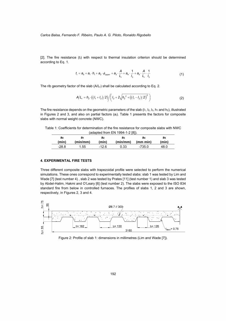
The fire resistance depends on the geometric parameters of the slab (l1, l2, l3, h1 and h2), illustrated in Figures 2 and 3, and also on partial factors (ai). Table 1 presents the factors for composite slabs with normal weight concrete (NWC).
Table 1: Coefficients for determination of the fire resistance for composite slabs with NWC (adapted from EN 1994-1-2 [8]).
a0
(min)
a1 (min/mm)
a2
(min) a3
(min/mm) a4
(mm min) a5
(min) -28.8 1.55 -12.6 0.33 -735.0 48.0
4. EXPERIMENTAL FIRE TESTS Three different composite slabs with trapezoidal profile were selected to perform the numerical simulations. These ones correspond to experimentally tested slabs: slab 1 was tested by Lim and Wade [7] (test number 4) , slab 2 was tested by Prates [11] (test number 1) and slab 3 was tested by Abdel-Halim, Hakmi and O’Leary [6] (test number 2). The slabs were exposed to the ISO 834 standard fire from below in controlled furnaces. The profiles of slabs 1, 2 and 3 are shown, respectively, in Figures 2, 3 and 4.
Figure 2: Profile of slab 1: dimensions in millimetres (Lim and Wade [7]).
3 4 50 1 13 3
2
1 1i upper
r r
A Aa a a
L l Lt a a h a
l
22r 2 1 2 2 2 1 2A L h l l 2 l 2 h l l 2
Numerical simulation of composite slabs with steel deck under fire conditions
193
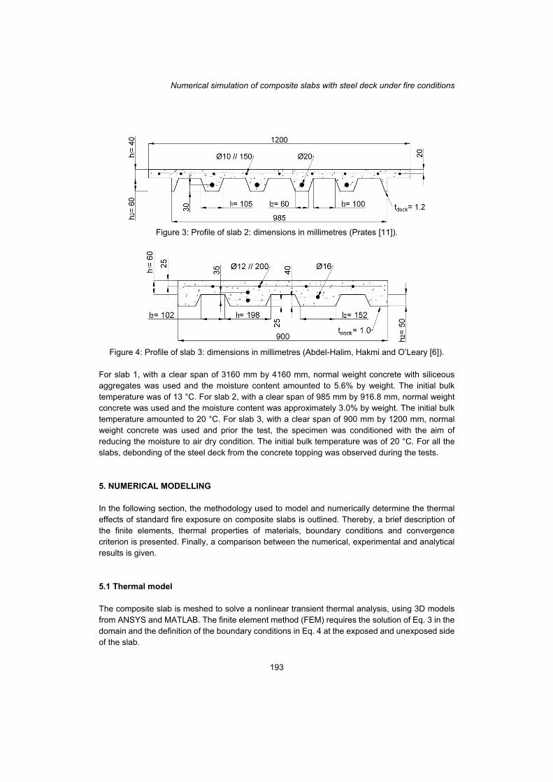
Figure 3: Profile of slab 2: dimensions in millimetres (Prates [11]).
Figure 4: Profile of slab 3: dimensions in millimetres (Abdel-Halim, Hakmi and O’Leary [6]).
For slab 1, with a clear span of 3160 mm by 4160 mm, normal weight concrete with siliceous aggregates was used and the moisture content amounted to 5.6% by weight. The initial bulk temperature was of 13 °C. For slab 2, with a clear span of 985 mm by 916.8 mm, normal weight concrete was used and the moisture content was approximately 3.0% by weight. The initial bulk temperature amounted to 20 °C. For slab 3, with a clear span of 900 mm by 1200 mm, normal weight concrete was used and prior the test, the specimen was conditioned with the aim of reducing the moisture to air dry condition. The initial bulk temperature was of 20 °C. For all the slabs, debonding of the steel deck from the concrete topping was observed during the tests. 5. NUMERICAL MODELLING In the following section, the methodology used to model and numerically determine the thermal effects of standard fire exposure on composite slabs is outlined. Thereby, a brief description of the finite elements, thermal properties of materials, boundary conditions and convergence criterion is presented. Finally, a comparison between the numerical, experimental and analytical results is given. 5.1 Thermal model The composite slab is meshed to solve a nonlinear transient thermal analysis, using 3D models from ANSYS and MATLAB. The finite element method (FEM) requires the solution of Eq. 3 in the domain and the definition of the boundary conditions in Eq. 4 at the exposed and unexposed side of the slab.
Carlos Balsa, Fernando F. Ribeiro, Paulo A. G. Piloto, Ronaldo Rigobello
194
(3)
(4)
In the equations above: T represents the temperature of each material; ρ(T) is the specific mass; Cp(T) is the specific heat; 𝜆(T) is the thermal conductivity; αc is the convection coefficient. Tg represents the gas temperature of the fire compartment, using the standard fire ISO 834 applied on the bottom part of the slab; ϕ is the view factor; εm is the emissivity of each material; εf represents the emissivity of the fire and σ represents the Stefan-Boltzmann constant. The view factor (ϕ) quantifies the geometric relation between the surface emitting radiation and the surface receiving radiation. The view factor of the lower flange of composite slabs (ϕlow) is given as 1. Owing to the obstruction to direct exposure caused by the ribs of the steel deck, the view factors of the web (ϕweb) and upper flange (ϕupper) are smaller than one. These view factors can be calculated as function of the geometric parameters of the slab, as follows.
(5)
(6)
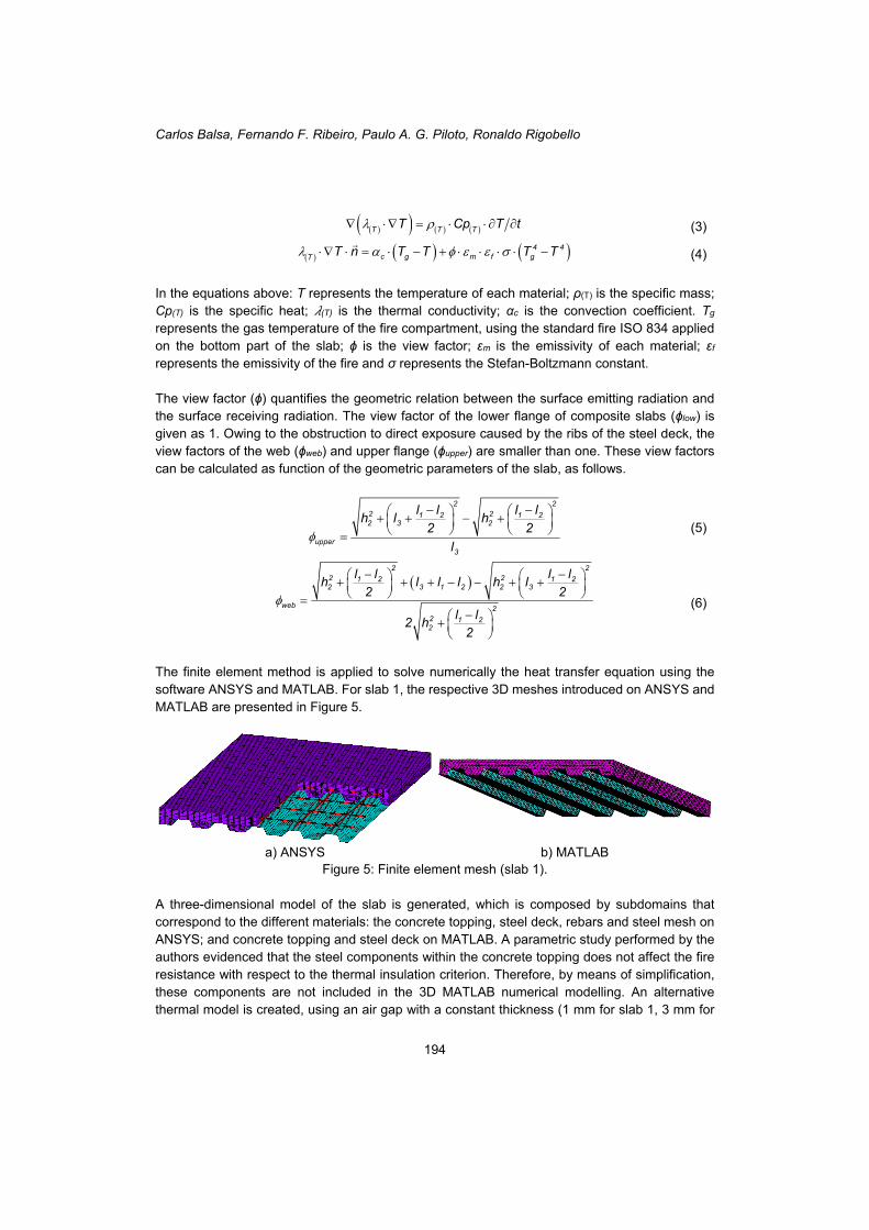
The finite element method is applied to solve numerically the heat transfer equation using the software ANSYS and MATLAB. For slab 1, the respective 3D meshes introduced on ANSYS and MATLAB are presented in Figure 5.
a) ANSYS b) MATLAB Figure 5: Finite element mesh (slab 1).
A three-dimensional model of the slab is generated, which is composed by subdomains that correspond to the different materials: the concrete topping, steel deck, rebars and steel mesh on ANSYS; and concrete topping and steel deck on MATLAB. A parametric study performed by the authors evidenced that the steel components within the concrete topping does not affect the fire resistance with respect to the thermal insulation criterion. Therefore, by means of simplification, these components are not included in the 3D MATLAB numerical modelling. An alternative thermal model is created, using an air gap with a constant thickness (1 mm for slab 1, 3 mm for
T T TT Cp T t
4 4c g m f gT T n T T T T
2 22 21 2 1 22 3 2
upper3
l l l lh l h
2 2
l
2 22 21 2 1 22 3 1 2 2 3
web 22 1 22
l l l lh l l l h l
2 2
l l2 h
2
Numerical simulation of composite slabs with steel deck under fire conditions
195
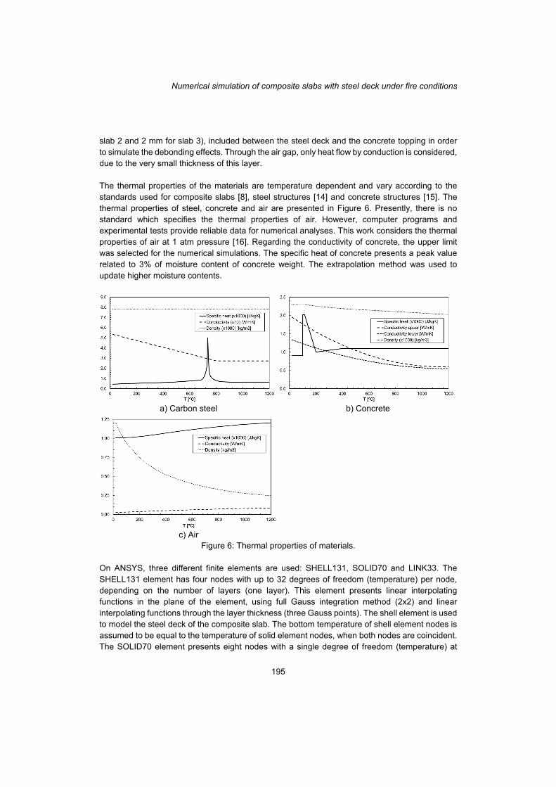
slab 2 and 2 mm for slab 3), included between the steel deck and the concrete topping in order to simulate the debonding effects. Through the air gap, only heat flow by conduction is considered, due to the very small thickness of this layer. The thermal properties of the materials are temperature dependent and vary according to the standards used for composite slabs [8], steel structures [14] and concrete structures [15]. The thermal properties of steel, concrete and air are presented in Figure 6. Presently, there is no standard which specifies the thermal properties of air. However, computer programs and experimental tests provide reliable data for numerical analyses. This work considers the thermal properties of air at 1 atm pressure [16]. Regarding the conductivity of concrete, the upper limit was selected for the numerical simulations. The specific heat of concrete presents a peak value related to 3% of moisture content of concrete weight. The extrapolation method was used to update higher moisture contents.
a) Carbon steel b) Concrete
c) Air Figure 6: Thermal properties of materials.
On ANSYS, three different finite elements are used: SHELL131, SOLID70 and LINK33. The SHELL131 element has four nodes with up to 32 degrees of freedom (temperature) per node, depending on the number of layers (one layer). This element presents linear interpolating functions in the plane of the element, using full Gauss integration method (2x2) and linear interpolating functions through the layer thickness (three Gauss points). The shell element is used to model the steel deck of the composite slab. The bottom temperature of shell element nodes is assumed to be equal to the temperature of solid element nodes, when both nodes are coincident. The SOLID70 element presents eight nodes with a single degree of freedom (temperature) at
Carlos Balsa, Fernando F. Ribeiro, Paulo A. G. Piloto, Ronaldo Rigobello
196
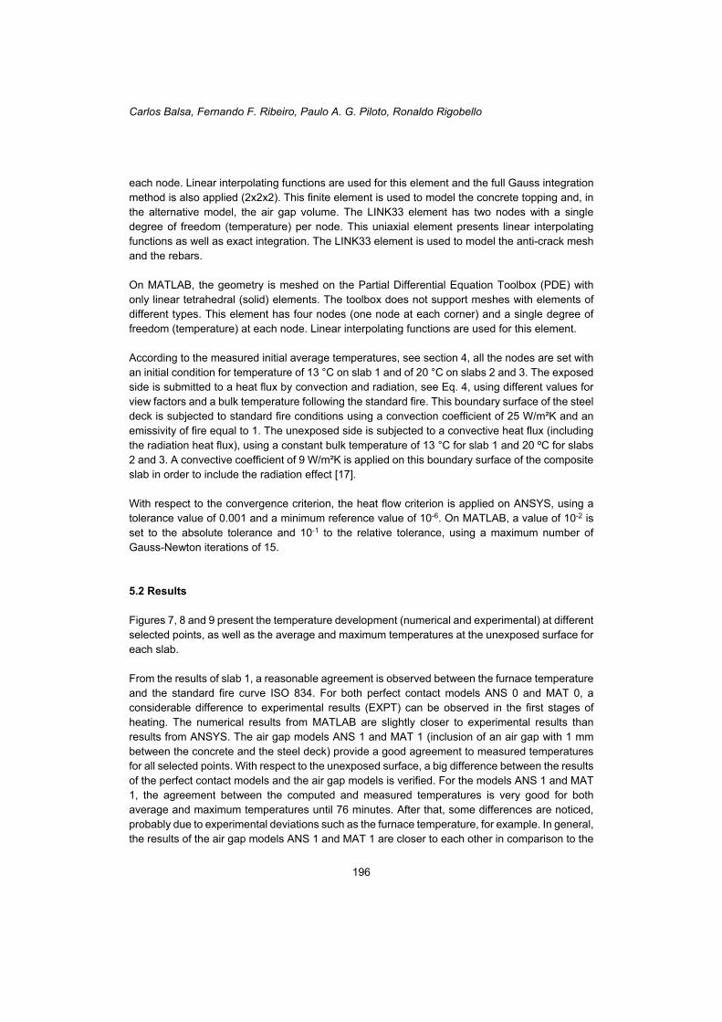
each node. Linear interpolating functions are used for this element and the full Gauss integration method is also applied (2x2x2). This finite element is used to model the concrete topping and, in the alternative model, the air gap volume. The LINK33 element has two nodes with a single degree of freedom (temperature) per node. This uniaxial element presents linear interpolating functions as well as exact integration. The LINK33 element is used to model the anti-crack mesh and the rebars. On MATLAB, the geometry is meshed on the Partial Differential Equation Toolbox (PDE) with only linear tetrahedral (solid) elements. The toolbox does not support meshes with elements of different types. This element has four nodes (one node at each corner) and a single degree of freedom (temperature) at each node. Linear interpolating functions are used for this element. According to the measured initial average temperatures, see section 4, all the nodes are set with an initial condition for temperature of 13 °C on slab 1 and of 20 °C on slabs 2 and 3. The exposed side is submitted to a heat flux by convection and radiation, see Eq. 4, using different values for view factors and a bulk temperature following the standard fire. This boundary surface of the steel deck is subjected to standard fire conditions using a convection coefficient of 25 W/m²K and an emissivity of fire equal to 1. The unexposed side is subjected to a convective heat flux (including the radiation heat flux), using a constant bulk temperature of 13 °C for slab 1 and 20 ºC for slabs 2 and 3. A convective coefficient of 9 W/m²K is applied on this boundary surface of the composite slab in order to include the radiation effect [17]. With respect to the convergence criterion, the heat flow criterion is applied on ANSYS, using a tolerance value of 0.001 and a minimum reference value of 10-6. On MATLAB, a value of 10-2 is set to the absolute tolerance and 10-1 to the relative tolerance, using a maximum number of Gauss-Newton iterations of 15. 5.2 Results Figures 7, 8 and 9 present the temperature development (numerical and experimental) at different selected points, as well as the average and maximum temperatures at the unexposed surface for each slab. From the results of slab 1, a reasonable agreement is observed between the furnace temperature and the standard fire curve ISO 834. For both perfect contact models ANS 0 and MAT 0, a considerable difference to experimental results (EXPT) can be observed in the first stages of heating. The numerical results from MATLAB are slightly closer to experimental results than results from ANSYS. The air gap models ANS 1 and MAT 1 (inclusion of an air gap with 1 mm between the concrete and the steel deck) provide a good agreement to measured temperatures for all selected points. With respect to the unexposed surface, a big difference between the results of the perfect contact models and the air gap models is verified. For the models ANS 1 and MAT 1, the agreement between the computed and measured temperatures is very good for both average and maximum temperatures until 76 minutes. After that, some differences are noticed, probably due to experimental deviations such as the furnace temperature, for example. In general, the results of the air gap models ANS 1 and MAT 1 are closer to each other in comparison to the
Numerical simulation of composite slabs with steel deck under fire conditions
197
perfect contact models ANS 0 and MAT 0. Small differences between the results of ANSYS and MATLAB models are observed, with exception of the average and maximum temperatures on the unexposed surface for the perfect contact models ANS 0 and MAT 0.
a) Selected points b) Unexposed side
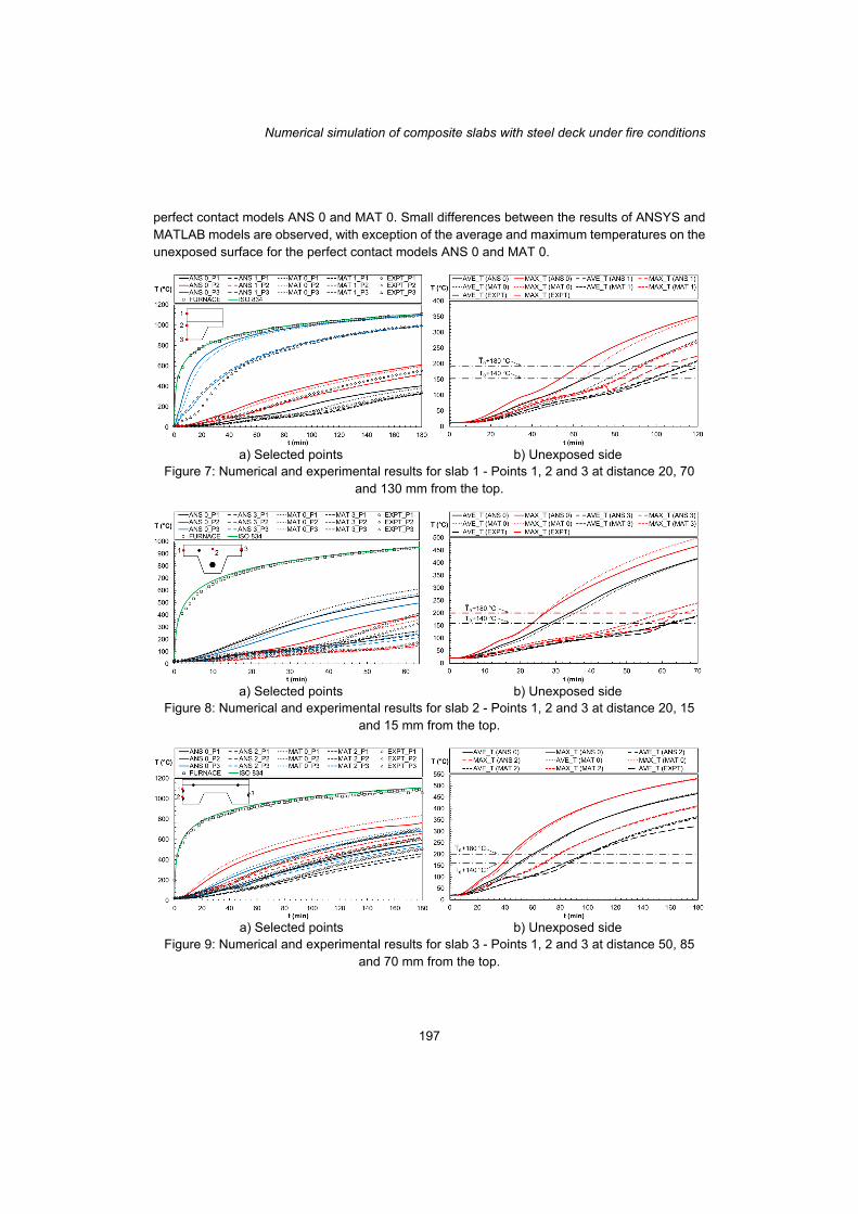
Figure 7: Numerical and experimental results for slab 1 - Points 1, 2 and 3 at distance 20, 70 and 130 mm from the top.
a) Selected points b) Unexposed side
Figure 8: Numerical and experimental results for slab 2 - Points 1, 2 and 3 at distance 20, 15 and 15 mm from the top.
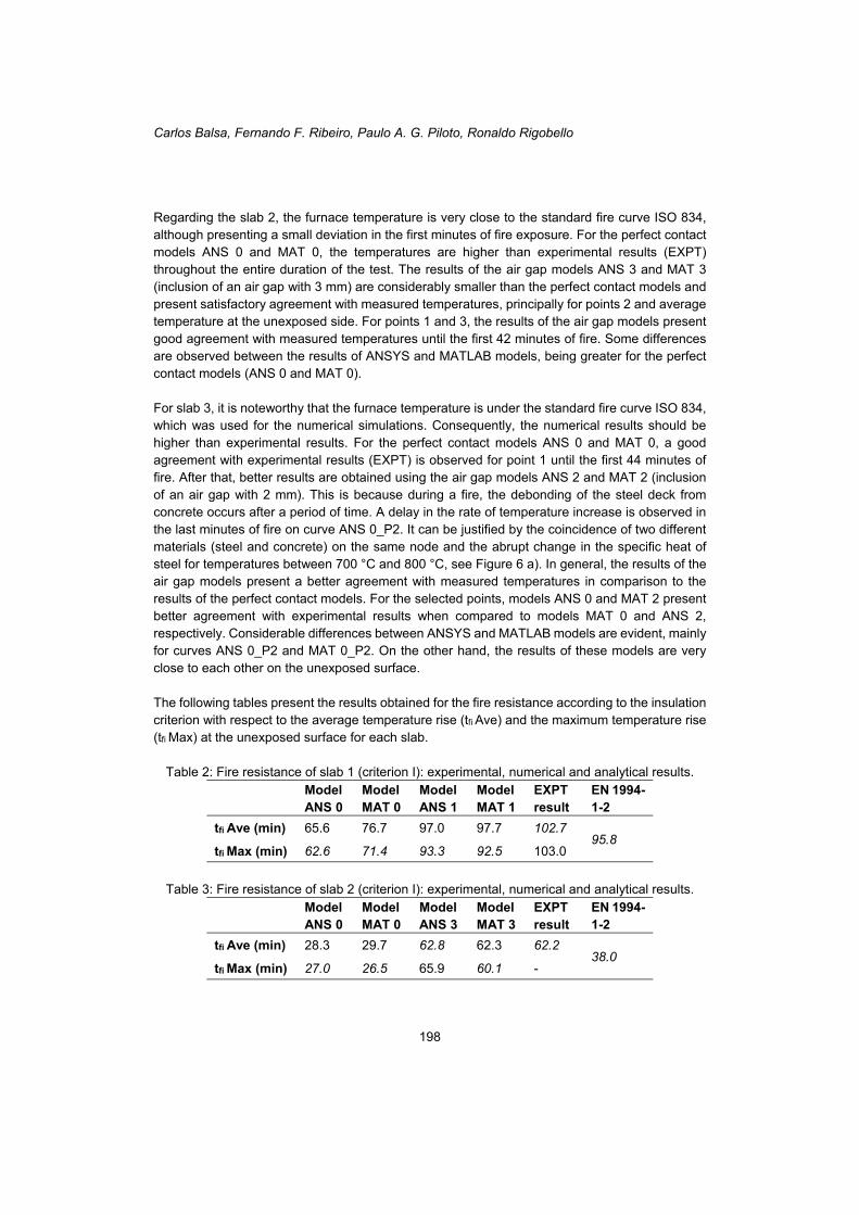
a) Selected points b) Unexposed side
Figure 9: Numerical and experimental results for slab 3 - Points 1, 2 and 3 at distance 50, 85 and 70 mm from the top.
Carlos Balsa, Fernando F. Ribeiro, Paulo A. G. Piloto, Ronaldo Rigobello
198
Regarding the slab 2, the furnace temperature is very close to the standard fire curve ISO 834, although presenting a small deviation in the first minutes of fire exposure. For the perfect contact models ANS 0 and MAT 0, the temperatures are higher than experimental results (EXPT) throughout the entire duration of the test. The results of the air gap models ANS 3 and MAT 3 (inclusion of an air gap with 3 mm) are considerably smaller than the perfect contact models and present satisfactory agreement with measured temperatures, principally for points 2 and average temperature at the unexposed side. For points 1 and 3, the results of the air gap models present good agreement with measured temperatures until the first 42 minutes of fire. Some differences are observed between the results of ANSYS and MATLAB models, being greater for the perfect contact models (ANS 0 and MAT 0). For slab 3, it is noteworthy that the furnace temperature is under the standard fire curve ISO 834, which was used for the numerical simulations. Consequently, the numerical results should be higher than experimental results. For the perfect contact models ANS 0 and MAT 0, a good agreement with experimental results (EXPT) is observed for point 1 until the first 44 minutes of fire. After that, better results are obtained using the air gap models ANS 2 and MAT 2 (inclusion of an air gap with 2 mm). This is because during a fire, the debonding of the steel deck from concrete occurs after a period of time. A delay in the rate of temperature increase is observed in the last minutes of fire on curve ANS 0_P2. It can be justified by the coincidence of two different materials (steel and concrete) on the same node and the abrupt change in the specific heat of steel for temperatures between 700 °C and 800 °C, see Figure 6 a). In general, the results of the air gap models present a better agreement with measured temperatures in comparison to the results of the perfect contact models. For the selected points, models ANS 0 and MAT 2 present better agreement with experimental results when compared to models MAT 0 and ANS 2, respectively. Considerable differences between ANSYS and MATLAB models are evident, mainly for curves ANS 0_P2 and MAT 0_P2. On the other hand, the results of these models are very close to each other on the unexposed surface. The following tables present the results obtained for the fire resistance according to the insulation criterion with respect to the average temperature rise (tfi Ave) and the maximum temperature rise (tfi Max) at the unexposed surface for each slab.
Table 2: Fire resistance of slab 1 (criterion I): experimental, numerical and analytical results.
Model ANS 0
Model MAT 0
Model ANS 1
Model MAT 1
EXPT result
EN 1994-1-2
tfi Ave (min) 65.6 76.7 97.0 97.7 102.7 95.8
tfi Max (min) 62.6 71.4 93.3 92.5 103.0
Table 3: Fire resistance of slab 2 (criterion I): experimental, numerical and analytical results.
Model ANS 0
Model MAT 0
Model ANS 3
Model MAT 3
EXPT result
EN 1994-1-2
tfi Ave (min) 28.3 29.7 62.8 62.3 62.2 38.0
tfi Max (min) 27.0 26.5 65.9 60.1 -
Numerical simulation of composite slabs with steel deck under fire conditions
199
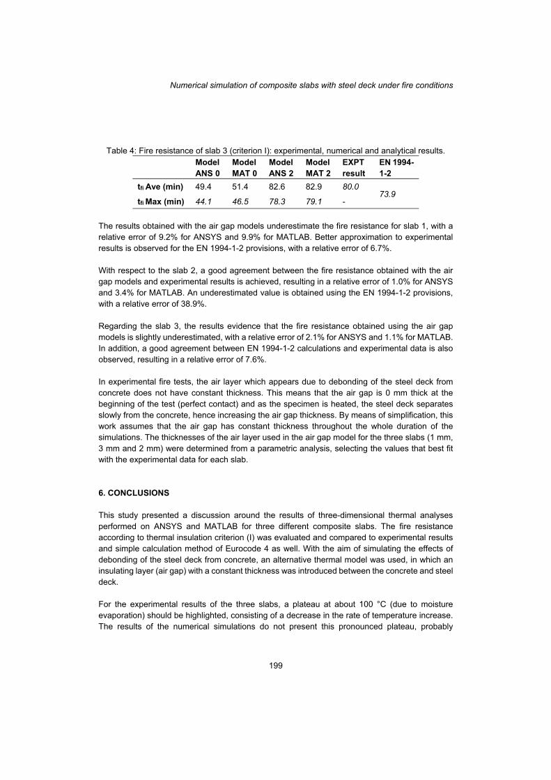
Table 4: Fire resistance of slab 3 (criterion I): experimental, numerical and analytical results.
Model ANS 0
Model MAT 0
Model ANS 2
Model MAT 2
EXPT result
EN 1994-1-2
tfi Ave (min) 49.4 51.4 82.6 82.9 80.0 73.9
tfi Max (min) 44.1 46.5 78.3 79.1 -
The results obtained with the air gap models underestimate the fire resistance for slab 1, with a relative error of 9.2% for ANSYS and 9.9% for MATLAB. Better approximation to experimental results is observed for the EN 1994-1-2 provisions, with a relative error of 6.7%. With respect to the slab 2, a good agreement between the fire resistance obtained with the air gap models and experimental results is achieved, resulting in a relative error of 1.0% for ANSYS and 3.4% for MATLAB. An underestimated value is obtained using the EN 1994-1-2 provisions, with a relative error of 38.9%. Regarding the slab 3, the results evidence that the fire resistance obtained using the air gap models is slightly underestimated, with a relative error of 2.1% for ANSYS and 1.1% for MATLAB. In addition, a good agreement between EN 1994-1-2 calculations and experimental data is also observed, resulting in a relative error of 7.6%. In experimental fire tests, the air layer which appears due to debonding of the steel deck from concrete does not have constant thickness. This means that the air gap is 0 mm thick at the beginning of the test (perfect contact) and as the specimen is heated, the steel deck separates slowly from the concrete, hence increasing the air gap thickness. By means of simplification, this work assumes that the air gap has constant thickness throughout the whole duration of the simulations. The thicknesses of the air layer used in the air gap model for the three slabs (1 mm, 3 mm and 2 mm) were determined from a parametric analysis, selecting the values that best fit with the experimental data for each slab. 6. CONCLUSIONS This study presented a discussion around the results of three-dimensional thermal analyses performed on ANSYS and MATLAB for three different composite slabs. The fire resistance according to thermal insulation criterion (I) was evaluated and compared to experimental results and simple calculation method of Eurocode 4 as well. With the aim of simulating the effects of debonding of the steel deck from concrete, an alternative thermal model was used, in which an insulating layer (air gap) with a constant thickness was introduced between the concrete and steel deck. For the experimental results of the three slabs, a plateau at about 100 °C (due to moisture evaporation) should be highlighted, consisting of a decrease in the rate of temperature increase. The results of the numerical simulations do not present this pronounced plateau, probably
Carlos Balsa, Fernando F. Ribeiro, Paulo A. G. Piloto, Ronaldo Rigobello
200
because localized moisture concentrations in the tests were higher than the uniform moisture content introduced in the thermal models for each slab. The maximum temperature rise criterion was decisive for the fire resistance according to thermal insulation criterion for most of the simulations. With respect to the experimental results, the average temperature rise criterion governed the fire resistance. The Eurocode 4 provisions underestimated the fire resistance for all the slabs, and for slab 2 in particular, a considerable difference was observed. The perfect contact models underestimate the fire resistance. Therefore, it is evident that the air gap models provide much better results for fire resistance from the thermal insulation standpoint when compared to the perfect contact models, reducing the temperature rise on the selected points and unexposed surface as well. In some cases, the results of ANSYS and MATLAB models presented noticeable differences for the same situation, that is, for a same point and type of model (perfect contact or air gap model). These differences can be justified by the presence of the steel components within the concrete layer (rebar and mesh) in the ANSYS model which are not included in the MATLAB model. Although not significantly affecting the fire resistance (I), these components can affect the temperature development at particular points. 7. REFERENCES [1] International Standard ISO 834, “Fire-resistance tests - Elements of building
construction.” 1975. [2] J. Jiang, A. Pintar, J. M. Weigand, J. A. Main, and F. Sadek, “Improved calculation method
for insulation-based fire resistance of composite slabs,” Fire Saf. J., 2019. [3] European Convention for Constructional Steelwork - Committee T3 - Fire Safety of Steel
Structures, “Calculation of the fire resistance of composite concrete slabs with profiled steel sheet exposed to the standard fire,” Brussels, 1983.
[4] R. Hamerlinck, “The behaviour of fire-exposed composite steel/concrete slabs,” Eindhoven University of Technology, 1991.
[5] C. Both, “The fire resistance of composite steel-concrete slabs,” Delft University of Technology, 1998.
[6] M. A. H. Abdel-Halim, M. R. Hakmi, and D. C. O’Leary, “Fire resistance of composite floor slabs using a model fire test facility,” Eng. Struct., vol. 21, no. 2, pp. 176–182, 1999.
[7] L. Lim and C. Wade, “Experimental fire tests of two-way concrete slabs,” Christchurch, 2002.
[8] CEN - European Committee for Standardization, EN 1994-1-2: Design of composite steel and concrete structures - Part 1-2: General rules - Structural fire design. Brussels, 2005.
[9] CEN- European Committee for Standardization, EN 1994-1-1: Design of composite steel and concrete structures - Part 1-1: General rules and rules for buildings. Brussels: CEN - European Committee for Standardization, 2004.
[10] S. Guo and C. G. Bailey, “Experimental behaviour of composite slabs during the heating and cooling fire stages,” Eng. Struct., vol. 33, pp. 563–571, 2011.
[11] L. M. S. Prates, “Numerical simulation of the fire behaviour of composite structures (slabs) [in portuguese],” Polytechnic Institute of Bragança, 2018.
Numerical simulation of composite slabs with steel deck under fire conditions
201
[12] CEN - European Committee for Standardization, EN 1363-1: Fire resistance tests - Part 1: General Requirements. Brussels, 2012.
[13] CEN - European Committee for Standardization, EN 1365-2: Fire resistance tests for load bearing elements - Part 2: Floors and roofs (Withdrawal). Brussels, 2014.
[14] CEN - European Committee for Standardization, EN 1993-1-2: Design of steel structures - Part 1-2: General rules - Structural fire design. Brussels, 2005.
[15] CEN - European Committee for Standardization, EN 1992-1-2: Design of concrete structures - Part 1-2: General rules - Structural fire design. Brussels, 2004.
[16] Y. A. Çengel and A. J. Ghajar, Heat and mass transfer: fundamentals & applications, Fifth edit. New York: McGraw-Hill Education, 2015.
[17] CEN - European Committee for Standardization, EN 1991-1-2: Actions on structures - Part 1-2: General actions - Actions on structures exposed to fire. Brussels, 2002.