Embed Size (px)
DESCRIPTION
4. GPU Overload Control & CPU Power Budge Management 0428_02
Citation preview
ED 0102 RELEASED GPU overload control and CPU power budget management EVOLIUM 20/04/2005 3BK 11202 0428 DSZZA 1/25
Site VELIZY
EVOLIUM™ SAS
Originators G. COSTAGLIOLA
S.BARRE
GPU Overload Control and CPU power budget management RELEASE B9
System : ALCATEL 900/BSS Sub-system : SYS-TLA Document Category : PRODUCT DEFINITION
ABSTRACT This document describes the GPU overload control and CPU Power budget handling.
Approvals Name App.
RJ. ACHARDMAUGER SYT Manager
JJ. BELLEGOD. ALBONICO MFS DPM
C. LEJEUNE SYT DPM
Name App.
REVIEW Ed. 01 Proposal 01 30/03/2005 MND/TD/SYT/SBA/205139_1.doc Ed. 01 Proposal 02 18/07/2005 MRD/TD/SYT/GCO/205260_1.doc
HISTORY Ed. 01 Proposal 01 28/01/2005 First proposal for B9 (Package 2).
This proposal in based on the Edition 2 Released of the B8 document. The B9 algorithm for a DSP to send the DSP-Load-Indication messages on PMU-PTU interface has been described.
Ed. 01 Proposal 02 27/04/2005 Compared to Ed 01 Proposal 01, the modifications are the following: - In section 5, description of the CPU overload protection in PPC, - In section 8, description of the memory overload protection in PTU, - Comments from review report of Edition 1 proposal 1 taken into account, - In §7.1, update of the “N” parameter hard coded in PTU according to BTP CR 160775.
ED 0102 RELEASED GPU overload control and CPU power budget management EVOLIUM 20/04/2005 3BK 11202 0428 DSZZA 2/25
Ed. 01 Released 18/07/2005 Compared to Ed 01 Proposal 02, the comments from
review report MRD/TD/SYT/GCO/205260 have been taken into account.
Ed. 02 Released 29/09/2006 Compared to Ed 01 Released, CR 3BKA20CBR181116 (simplification of the PTU memory overload mechanism) has been taken into account.
TABLE OF CONTENT 1 SCOPE.............................................................................................................................................. 5 2 OBJECTIVE...................................................................................................................................... 6 3 INTRODUCTION............................................................................................................................... 7 4 GPU ARCHITECTURE REMINDER................................................................................................. 8 5 CPU OVERLOAD PROTECTION IN PPC ..................................................................................... 11 5.1 PPC-CPU overload detection and indicator............................................................ 11 5.2 PMU-CPU overload control actions ......................................................................... 13
6 MEMORY OVERLOAD PROTECTION IN PMU ............................................................................ 15 7 CPU OVERLOAD PROTECTION IN PTU...................................................................................... 16 7.1 Computation of the DSP CPU load .......................................................................... 16 7.2 DSP CPU load notifications sent to RRM................................................................ 17 7.3 RRM behaviour in case of loaded or overloaded DSP........................................... 18
8 MEMORY OVERLOAD PROTECTION IN PTU............................................................................. 19 9 LOAD RELATED PARAMETERS.................................................................................................. 22 9.1 PMU load related parameters ................................................................................... 22 9.2 DSP load related parameters.................................................................................... 22
10 GLOSSARY AND ABBREVIATIONS ............................................................................................ 24 TABLE OF FIGURES
Figure 1: Protected vs. non-protected system behaviour when overload...................................... 7 Figure 2: GPU Telecom Architecture .................................................................................................. 8 Figure 3: Illustrations of DSP load notifications from PTU to PMU............................................... 18 Figure 4 Transitions between DSP memory congestion states. .................................................... 20
ED 0102 RELEASED GPU overload control and CPU power budget management EVOLIUM 20/04/2005 3BK 11202 0428 DSZZA 3/25
TABLE OF TABLES
Table 1: Priority of the main actions to be performed by the MFS .................................................. 6 Table 2: Split of MFS functions between PPC and DSP.................................................................. 10 Table 3: Rules for updating PMU_CPU_Overload_indicator. ......................................................... 12 Table 4: Example of PMU_CPU_Overload_indicator variations..................................................... 12 Table 5: Actions undertaken according to PMU_CPU_Overload_indicator. ................................ 13 Table 7: PMU load related parameters .............................................................................................. 22 Table 9: DSP load related parameters............................................................................................... 23
ED 0102 RELEASED GPU overload control and CPU power budget management EVOLIUM 20/04/2005 3BK 11202 0428 DSZZA 4/25
INTERNAL REFERENCED DOCUMENTS Not applicable
REFERENCED DOCUMENTS [1] 3BK 11202 0391 DSZZA FBS-GPRS-RADIO-INTERFACE-RRM SUB-LAYER (PCC)
RELEASE B9 [2] 3BK 11202 0393 DSZZA FBS GPRS - Radio interface – MAC sublayer RELEASE B9
[3] 3BK 11202 0392 DSZZA FBS GPRS - Radio interface – RLC sublayer RELEASE B9
[4] 3BK 11203 0086 DSZZA Alcatel Radio System Architecture RELEASE B8
[5] 3BK 11203 0292 DSZZA FBS GPRS-TELECOM PRESENTATION RELEASE B9
[6] 3BK 11203 0115 DSZZA BSS Traffic Model and Capacity : PS part RELEASE B9
[7] 3BK 11203 0101 DSZZA MFS Counters Catalogue RELEASE B9
[8] 3BK 11203 0103 DSZZA BSS Telecom parameters RELEASE B9 [9] 3BK 11202 0390 DSZZA FBS-GPRS-RADIO-INTERFACE-RRM SUB-LAYER (PRH)
RELEASE B9
RELATED DOCUMENTS [10] Evolium/R&D/SYT/Telecom/EBR/0932.2002 Ed 08 Technical delta note for the feature “NC2 for MS in packet transfer mode” [11] VAL/TD/SYT/AFR/112.2002/ed3 B8 Impacts on GPU Overload control and proposal for improvements
PREFACE
OPEN POINTS / RESTRICTIONS
ED 0102 RELEASED GPU overload control and CPU power budget management EVOLIUM 20/04/2005 3BK 11202 0428 DSZZA 5/25
1 SCOPE The scope of this document is to give rules for handling memory and CPU budget during overload situations within GPU (GPRS Processing Unit).
The following GPU resources are considered in this document.
� In the Packet Management Unit (PMU):
• GPU Host processor (or PPC)
• Memory
� In the Packet Transmission Unit (PTU):
• DSP processor
• DSP memory
ED 0102 RELEASED GPU overload control and CPU power budget management EVOLIUM 20/04/2005 3BK 11202 0428 DSZZA 6/25
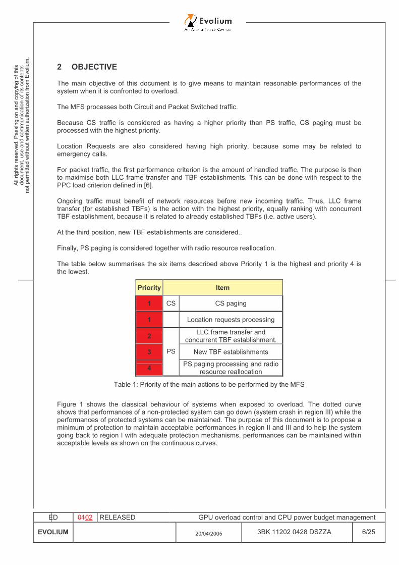
2 OBJECTIVE The main objective of this document is to give means to maintain reasonable performances of the system when it is confronted to overload. The MFS processes both Circuit and Packet Switched traffic. Because CS traffic is considered as having a higher priority than PS traffic, CS paging must be processed with the highest priority. Location Requests are also considered having high priority, because some may be related to emergency calls. For packet traffic, the first performance criterion is the amount of handled traffic. The purpose is then to maximise both LLC frame transfer and TBF establishments. This can be done with respect to the PPC load criterion defined in [6]. Ongoing traffic must benefit of network resources before new incoming traffic. Thus, LLC frame transfer (for established TBFs) is the action with the highest priority, equally ranking with concurrent TBF establishment, because it is related to already established TBFs (i.e. active users). At the third position, new TBF establishments are considered.. Finally, PS paging is considered together with radio resource reallocation. The table below summarises the six items described above Priority 1 is the highest and priority 4 is the lowest.
Priority Item 1 CS CS paging
1 Location requests processing
2 LLC frame transfer and concurrent TBF establishment.
3 New TBF establishments 4
PS PS paging processing and radio
resource reallocation Table 1: Priority of the main actions to be performed by the MFS
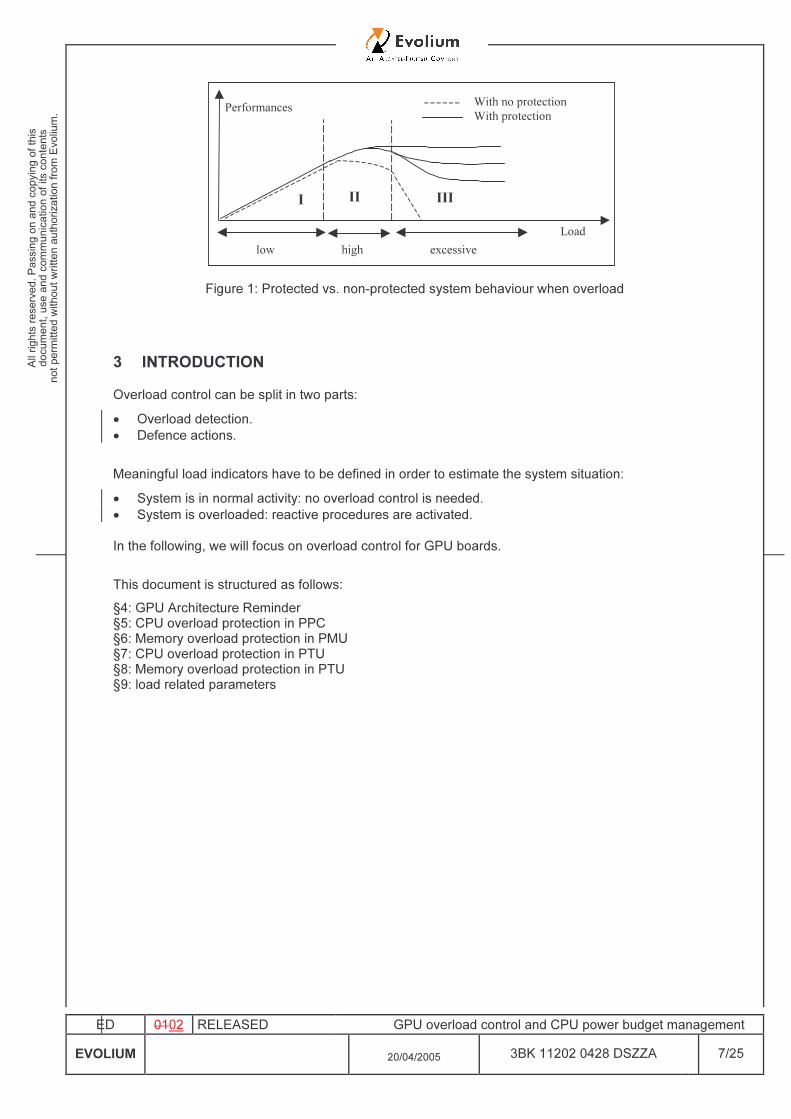
Figure 1 shows the classical behaviour of systems when exposed to overload. The dotted curve shows that performances of a non-protected system can go down (system crash in region III) while the performances of protected systems can be maintained. The purpose of this document is to propose a minimum of protection to maintain acceptable performances in region II and III and to help the system going back to region I with adequate protection mechanisms, performances can be maintained within acceptable levels as shown on the continuous curves.
ED 0102 RELEASED GPU overload control and CPU power budget management EVOLIUM 20/04/2005 3BK 11202 0428 DSZZA 7/25
Load
Performances With no protectionWith protection
low high excessive
II IIII
Figure 1: Protected vs. non-protected system behaviour when overload
3 INTRODUCTION Overload control can be split in two parts: • Overload detection. • Defence actions. Meaningful load indicators have to be defined in order to estimate the system situation: • System is in normal activity: no overload control is needed. • System is overloaded: reactive procedures are activated. In the following, we will focus on overload control for GPU boards. This document is structured as follows: §4: GPU Architecture Reminder §5: CPU overload protection in PPC §6: Memory overload protection in PMU §7: CPU overload protection in PTU §8: Memory overload protection in PTU §9: load related parameters
ED 0102 RELEASED GPU overload control and CPU power budget management EVOLIUM 20/04/2005 3BK 11202 0428 DSZZA 8/25
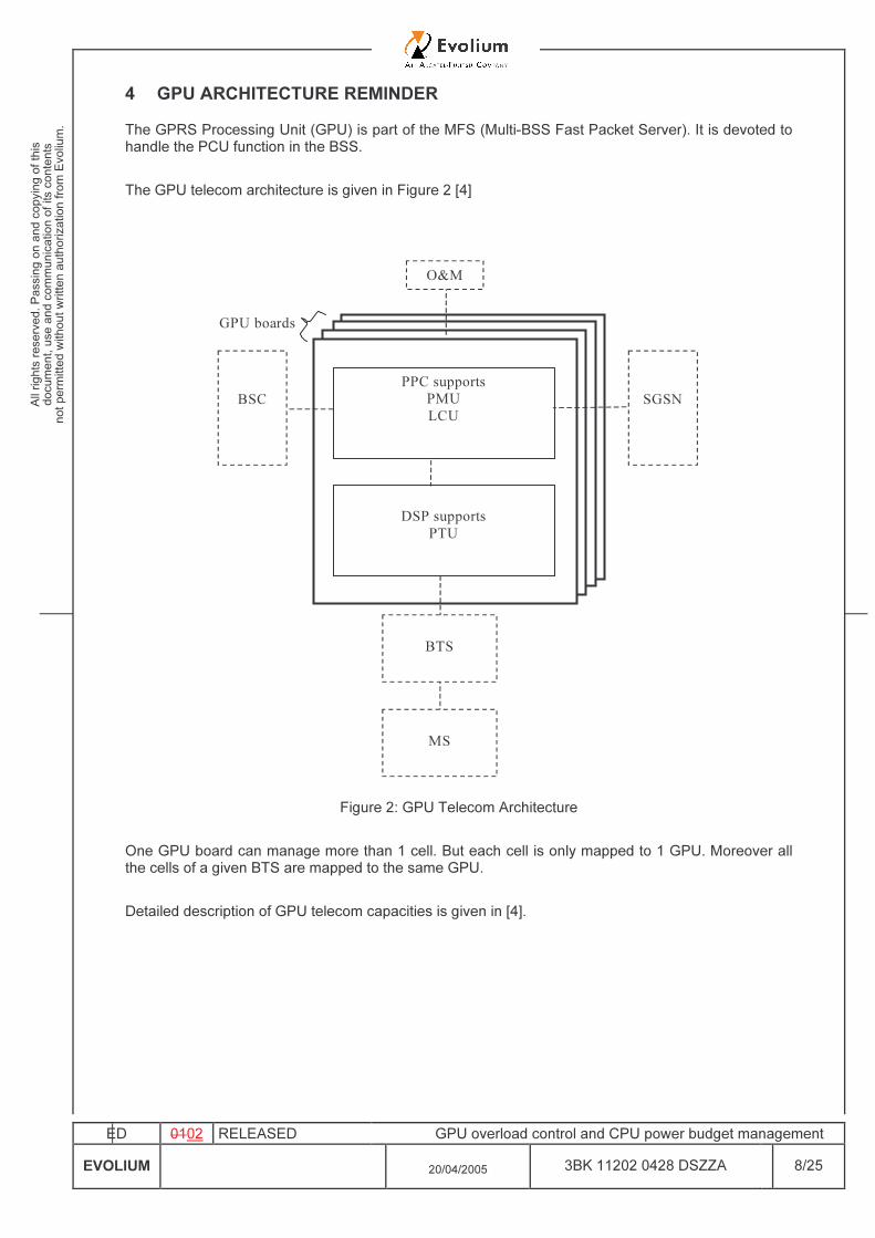
4 GPU ARCHITECTURE REMINDER The GPRS Processing Unit (GPU) is part of the MFS (Multi-BSS Fast Packet Server). It is devoted to handle the PCU function in the BSS.
The GPU telecom architecture is given in Figure 2 [4]
BSC SGSNPPC supports
PMULCU
DSP supportsPTU
GPU boards
O&M
BTS
MS
Figure 2: GPU Telecom Architecture
One GPU board can manage more than 1 cell. But each cell is only mapped to 1 GPU. Moreover all the cells of a given BTS are mapped to the same GPU.
Detailed description of GPU telecom capacities is given in [4].
ED 0102 RELEASED GPU overload control and CPU power budget management EVOLIUM 20/04/2005 3BK 11202 0428 DSZZA 9/25
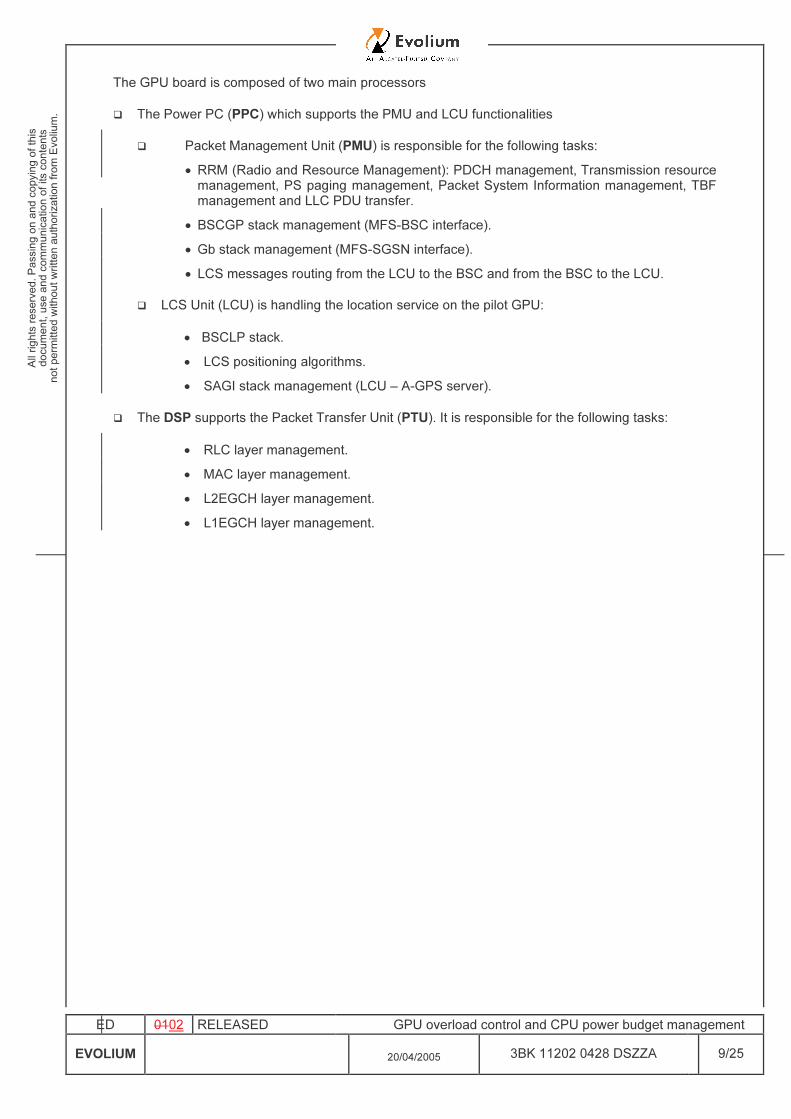
The GPU board is composed of two main processors � The Power PC (PPC) which supports the PMU and LCU functionalities � Packet Management Unit (PMU) is responsible for the following tasks:
• RRM (Radio and Resource Management): PDCH management, Transmission resource management, PS paging management, Packet System Information management, TBF management and LLC PDU transfer.
• BSCGP stack management (MFS-BSC interface). • Gb stack management (MFS-SGSN interface). • LCS messages routing from the LCU to the BSC and from the BSC to the LCU.
� LCS Unit (LCU) is handling the location service on the pilot GPU:
• BSCLP stack. • LCS positioning algorithms. • SAGI stack management (LCU – A-GPS server).
� The DSP supports the Packet Transfer Unit (PTU). It is responsible for the following tasks:
• RLC layer management. • MAC layer management. • L2EGCH layer management. • L1EGCH layer management.
ED 0102 RELEASED GPU overload control and CPU power budget management EVOLIUM 20/04/2005 3BK 11202 0428 DSZZA 10/25
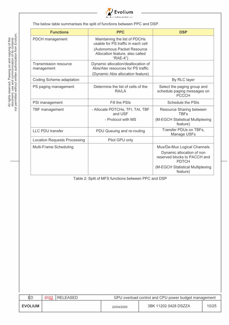
The below table summarises the split of functions between PPC and DSP.
Functions PPC DSP PDCH management Maintaining the list of PDCHs
usable for PS traffic in each cell (Autonomous Packet Resource Allocation feature, also called
“RAE-4”)
Transmission resource management
Dynamic allocation/deallocation of Abis/Ater resources for PS traffic (Dynamic Abis allocation feature)
Coding Scheme adaptation By RLC layer PS paging management Determine the list of cells of the
RA/LA Select the paging group and schedule paging messages on
PCCCH PSI management Fill the PSIs Schedule the PSIs TBF management - Allocate PDTCHs, TFI, TAI, TBF
and USF - Protocol with MS
Resource Sharing between TBFs
(M-EGCH Statistical Multiplexing feature)
LLC PDU transfer PDU Queuing and re-routing Transfer PDUs on TBFs, Manage USFs
Location Requests Processing Pilot GPU only Multi-Frame Scheduling Mux/De-Mux Logical Channels
Dynamic allocation of non reserved blocks to PACCH and
PDTCH (M-EGCH Statistical Multiplexing
feature) Table 2: Split of MFS functions between PPC and DSP
ED 0102 RELEASED GPU overload control and CPU power budget management EVOLIUM 20/04/2005 3BK 11202 0428 DSZZA 11/25
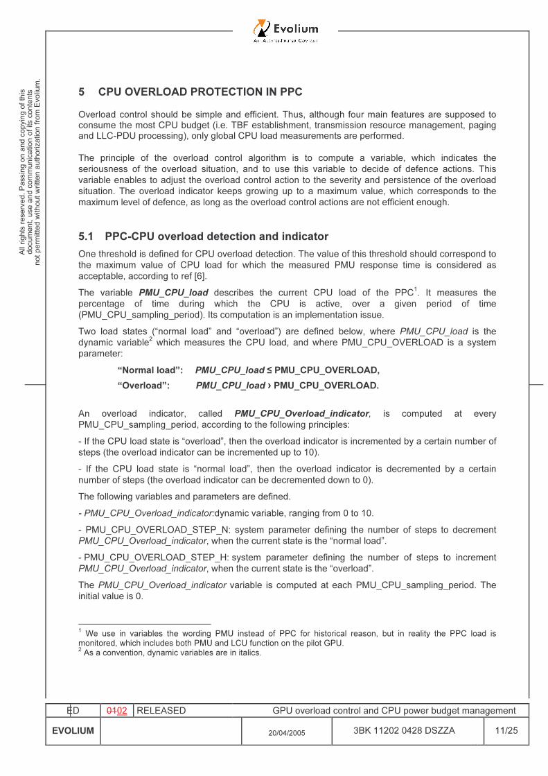
5 CPU OVERLOAD PROTECTION IN PPC Overload control should be simple and efficient. Thus, although four main features are supposed to consume the most CPU budget (i.e. TBF establishment, transmission resource management, paging and LLC-PDU processing), only global CPU load measurements are performed. The principle of the overload control algorithm is to compute a variable, which indicates the seriousness of the overload situation, and to use this variable to decide of defence actions. This variable enables to adjust the overload control action to the severity and persistence of the overload situation. The overload indicator keeps growing up to a maximum value, which corresponds to the maximum level of defence, as long as the overload control actions are not efficient enough.
5.1 PPC-CPU overload detection and indicator One threshold is defined for CPU overload detection. The value of this threshold should correspond to the maximum value of CPU load for which the measured PMU response time is considered as acceptable, according to ref [6]. The variable PMU_CPU_load describes the current CPU load of the PPC1. It measures the percentage of time during which the CPU is active, over a given period of time (PMU_CPU_sampling_period). Its computation is an implementation issue. Two load states (“normal load” and “overload”) are defined below, where PMU_CPU_load is the dynamic variable2 which measures the CPU load, and where PMU_CPU_OVERLOAD is a system parameter:
“Normal load”: PMU_CPU_load ≤ PMU_CPU_OVERLOAD, “Overload”: PMU_CPU_load › PMU_CPU_OVERLOAD.
An overload indicator, called PMU_CPU_Overload_indicator, is computed at every PMU_CPU_sampling_period, according to the following principles: - If the CPU load state is “overload”, then the overload indicator is incremented by a certain number of steps (the overload indicator can be incremented up to 10). - If the CPU load state is “normal load”, then the overload indicator is decremented by a certain number of steps (the overload indicator can be decremented down to 0). The following variables and parameters are defined. - PMU_CPU_Overload_indicator:dynamic variable, ranging from 0 to 10. - PMU_CPU_OVERLOAD_STEP_N: system parameter defining the number of steps to decrement PMU_CPU_Overload_indicator, when the current state is the “normal load”. - PMU_CPU_OVERLOAD_STEP_H: system parameter defining the number of steps to increment PMU_CPU_Overload_indicator, when the current state is the “overload”. The PMU_CPU_Overload_indicator variable is computed at each PMU_CPU_sampling_period. The initial value is 0.
1 We use in variables the wording PMU instead of PPC for historical reason, but in reality the PPC load is monitored, which includes both PMU and LCU function on the pilot GPU. 2 As a convention, dynamic variables are in italics.
ED 0102 RELEASED GPU overload control and CPU power budget management EVOLIUM 20/04/2005 3BK 11202 0428 DSZZA 12/25
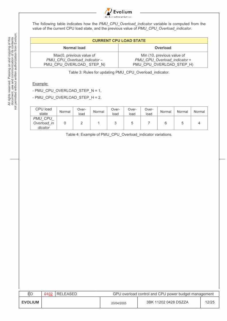
The following table indicates how the PMU_CPU_Overload_indicator variable is computed from the value of the current CPU load state, and the previous value of PMU_CPU_Overload_indicator.
CURRENT CPU LOAD STATE Normal load Overload
Max(0, previous value of PMU_CPU_Overload_indicator –
PMU_CPU_OVERLOAD_ STEP_N) Min (10, previous value of
PMU_CPU_Overload_indicator + PMU_CPU_OVERLOAD_STEP_H)
Table 3: Rules for updating PMU_CPU_Overload_indicator.
Example: - PMU_CPU_OVERLOAD_STEP_N = 1, - PMU_CPU_OVERLOAD_STEP_H = 2, CPU load state Normal Over-
load Normal Over-load
Over-load
Over-load Normal Normal Normal
PMU_CPU_Overload_in
dicator 0 2 1 3 5 7 6 5 4
Table 4: Example of PMU_CPU_Overload_indicator variations.
ED 0102 RELEASED GPU overload control and CPU power budget management EVOLIUM 20/04/2005 3BK 11202 0428 DSZZA 13/25
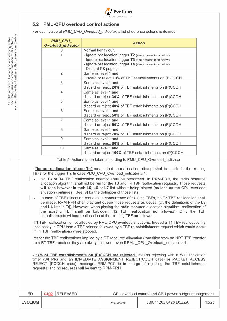
5.2 PMU-CPU overload control actions For each value of PMU_CPU_Overload_indicator, a list of defense actions is defined.
PMU_CPU_ Overload_indicator Action
0 Normal behaviour. 1 - Ignore reallocation trigger T2 (see explanations below)
- Ignore reallocation trigger T3 (see explanations below) - Ignore reallocation trigger T4 (see explanations below) - Discard PS paging
2 Same as level 1 and Discard or reject 10% of TBF establishments on (P)CCCH
3 Same as level 1 and discard or reject 20% of TBF establishments on (P)CCCH
4 Same as level 1 and discard or reject 30% of TBF establishments on (P)CCCH
5 Same as level 1 and discard or reject 40% of TBF establishments on (P)CCCH
6 Same as level 1 and discard or reject 50% of TBF establishments on (P)CCCH
7 Same as level 1 and discard or reject 60% of TBF establishments on (P)CCCH
8 Same as level 1 and discard or reject 70% of TBF establishments on (P)CCCH
9 Same as level 1 and discard or reject 80% of TBF establishments on (P)CCCH
10 Same as level 1 and discard or reject 100% of TBF establishments on (P)CCCH
Table 5: Actions undertaken according to PMU_CPU_Overload_indicator. - “Ignore reallocation trigger Tn” means that no reallocation attempt shall be made for the existing TBFs for the trigger Tn. In case PMU_CPU_Overload_indicator ≥ 1: - No T3 or T4 TBF reallocation attempt shall be performed. In RRM-PRH, the radio resource
allocation algorithm shall not be run for the T3 and T4 TBF reallocation requests. Those requests will keep however in their L5, L6 or L7 list without being played (as long as the CPU overload situation continues). See [9] for the definition of those lists.
- In case of TBF allocation requests in concurrence of existing TBFs, no T2 TBF reallocation shall be made. RRM-PRH shall play and queue those requests as ususal (cf. the definitions of the L3 and L4 lists in [9]). However, when playing the radio resource allocation algorithm, reallocation of the existing TBF shall be forbidden (T2 TBF reallocation not allowed). Only the TBF establishments without reallocation of the existing TBF are allowed.
T1 TBF reallocation is not affected by PMU CPU overload situations. Indeed a T1 TBF reallocation is less costly in CPU than a TBF release followed by a TBF re-establishment request which would occur if T1 TBF reallocations were stopped. As for the TBF reallocations implied by a RT resource allocation (transition from an NRT TBF transfer to a RT TBF transfer), they are always allowed, even if PMU_CPU_Overload_indicator ≥ 1. - “x% of TBF establishments on (P)CCCH are rejected” means rejecting with a Wait Indication timer (WI_PR) and an IMMEDIATE ASSIGNMENT REJECT(CCCH case) or PACKET ACCESS REJECT (PCCCH case) message. RRM-PCC is in charge of rejecting the TBF establishment requests, and no request shall be sent to RRM-PRH.
ED 0102 RELEASED GPU overload control and CPU power budget management EVOLIUM 20/04/2005 3BK 11202 0428 DSZZA 14/25
- Interactions with the QoS feature: In case of UL one-phase access, it is not possible to immediately know if the TBF establishment on (P)CCCH is associated to an RT PFC or not. Indeed, such an association can only be done when the TLLI of the MS is known (cf. contention resolution phase in RLC [3]), which occurs after the TBF establishment. Thus, in case PMU_CPU_Overload_indicator ≥ 2, some UL TBF establishments on (P)CCCH may be rejected even if an RT PFC was previously created with success for the MS. To simplify, this mechanism is applied to all the cases (UL one-phase and UL two-phase access). On the other hand, the RT PFC creation requests (and the RT PFC modification requests) shall be managed as usual in case of PMU CPU overload situation (only the TBF-related behaviour is modified by limiting the acceptance of TBF establishments on (P)CCCH, but the RT-PFC-related behaviour is unchanged). - Other comments: - No specific action is undertaken for the following procedures because they have a high priority and/or because they are not likely to cause CPU overload on their own: • LCS: some location requests may correspond to emergency call, and it is not possible to
discriminate between emergency and non-emergency. LCS traffic in B9 is expected to be quite low.
• NC2 feature: CPU cost per TBF is very low. • CS Paging: it is considered to have priority over all PS procedures. • Transmission resource management (Dynamic Abis allocation feature): to simplify, the
transmission resource management procedures are not blocked during PMU CPU overload situations. Note: the fact of forbidding TBF reallocations (for T2, T3 and T4 triggers) and the fact of rejecting a certain percentage of UL TBF establishments on (P)CCCH will tend, to some extent, to limit the number of GCH establishments and of inter-cell/intra-cell GCH preemptions.
- With the above strategy, in case of severe PMU CPU overload, new incoming traffic can be completely stopped3 in a maximum time equal to (PMU_CPU_sampling_period x 10 / PMU_CPU_OVERLOAD_STEP_H). The return to normal behaviour, after the overload has disappeared, can be obtained in a maximum time equal to (PMU_CPU_sampling_period x 10 / PMU_CPU_OVERLOAD_STEP_N). - The CPU overload control does not discard LLC PDUs4 for the already-established TBFs, but this can happen with the memory overload control (see section 6).
3 Provided the Wait Indication timer is set to a long enough value. 4 It is possible to produce CPU overload in PMU with a pure flow of LLC PDUs for already-established TBFs, but this case is not considered as very realistic and we rely on memory protection mechanism in this case.
ED 0102 RELEASED GPU overload control and CPU power budget management EVOLIUM 20/04/2005 3BK 11202 0428 DSZZA 15/25
6 MEMORY OVERLOAD PROTECTION IN PMU Because memory needs will not be the same for all cells (traffic is geography and time dependent), PMU memory is managed at the GPU level. The GPU level management allows a dynamic and flexible occupation according to traffic distribution within PS active cells. The memory is composed of two pools, a static pool and a dynamic pool. The static memory pool is reserved for static contexts). It is dedicated to the following:
• Code • Variables, Counters, Debug traces • Cell contexts • TRX contexts
The remaining amount of memory is managed dynamically. Cells having momentarily high traffic load are allowed to use a bigger amount of memory. This common memory pool is dedicated to the following:
• MS contexts • TBF contexts • PDCH contexts • PDU queueing
The detailed description of the memory requirements can be found in document reference [6]. The static pool is not concerned with overload. For the PDU queuing dynamic pool, thresholds are defined in order to detect and then react to memory overload states. Overload reaction is done through a flow control with the SGSN. It is aimed at reducing gradually the PDU flow sent from the SGSN to the MFS. In case some SGSN would not implement BVC flow control, additional memory protection is implemented in the PMU. In this case, no LLC-discard is sent towards the SGSN. At the first level of buffer congestion (those used to store the PDUs), RRM a) applies a bvc leak rate equals to 0 b) discards the DL PDU c) drops the UL PDU At the second level of congestion, Gb drops all DL LLC PDU.
ED 0102 RELEASED GPU overload control and CPU power budget management EVOLIUM 20/04/2005 3BK 11202 0428 DSZZA 16/25
7 CPU OVERLOAD PROTECTION IN PTU
7.1 Computation of the DSP CPU load Each DSP computes its CPU load to provide it regularly to PMU. This computation is performed in two steps:
- a measurement of the DSP load in a 20 ms period, - the filtering of the measurements during T_DSP_LOAD_REPORT timer (see [8]) before
reporting the percentage of DSP load to PMU. • Measurement of the DSP load per 20 ms period: The LOAD background task is an asynchronous processing in PTU and is activated when the other entire PTU processing tasks have been completed and there is still some free time until the end of the 20 ms period. This function computes the percentage of time the DSP is in idle mode and then deduces the DSP load during that period of time. Per 20 ms the idle processing time (noted T1) is measured and the corresponding load percentage is computed as (20-T1)/20. Note that this task may be activated several times in the same 20ms period. The LOAD task is also in charge of sending the DSP-Load-Indication to PMU. It may happen that the LOAD task is not activated during a 20ms period due to a high DSP load (e.g DSP load reaches 100%). Then a defence is necessary to ensure that a DSP-Load-Indication is sent to PMU at some time. The FORCED LOAD task forces to call LOAD task after DELAY_FORCED_LOAD_REPORT consecutive 20 ms periods during which the LOAD task did not run. DELAY_FORCED_LOAD_REPORT is a PTU SW hard coded parameter (for more details, please refer to [8]). It means that the current DSP load procedure does not guarantee an immediate reporting of the DSP Load when it reaches 100%. A possible delay may occur until the FORCED_LOAD task triggers the sending of the DSP_LOAD_INDICATION message to PMU. N.B: if really needed, a possible improvement would be that the FORCED LOAD task has a flag to memorize if “it remains at least one threshold crossing among DSP_LOAD_THR_1 and DSP_LOAD_THR_2 to notify to PMU” (e.g flag=TRUE in this case). At each 20 ms period when this FORCED LOAD task runs, it tests the value of this flag and if flag=TRUE, it forces a call to the LOAD TASK. This improvement should allow an immediate reporting of high DSP load, with no (20ms x DELAY_FORCED_LOAD_REPORT) delay. • Filtering of the measurements: Several measurements are performed before a DSP load is reported to PMU. Once the load percentage in this 20ms, a filtering function uses it as an input to determine the DSP load taking into account the previous measurements since the last notification to PMU. It is based on the DSP_LOAD_FORGETTING_FACTOR parameter (see [8]).
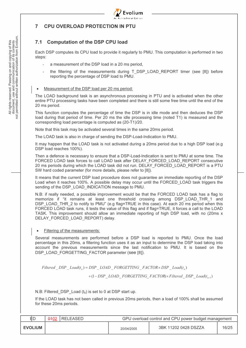
)(____)(__ nn tLoadDSPFACTORFORGETTINGLOADDSPtLoadDSPFiltered ×= )(__)___1( 1−×−+ ntLoadDSPFilteredFACTORFORGETTINGLOADDSP
N.B: Filtered_DSP_Load (t0) is set to 0 at DSP start up. If the LOAD task has not been called in previous 20ms periods, then a load of 100% shall be assumed for these 20ms periods.
ED 0102 RELEASED GPU overload control and CPU power budget management EVOLIUM 20/04/2005 3BK 11202 0428 DSZZA 17/25
7.2 DSP CPU load notifications sent to RRM
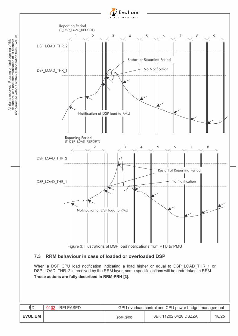
Each DSP regularly sends its current CPU load (after filtering, see section 7.1) to PMU. The message which is used on PMU-PTU interface is DSP-Load-Indication. When received by the RRM layer, some specific actions will be undertaken depending on the current CPU load of the DSP (see [9] for the behaviour of RRM layer). The sending of the DSP-Load-Indication messages is both based on a periodical process and on spontaneous notifications when the CPU load exceeds some thresholds (DSP_LOAD_THR_1 and DSP_LOAD_THR_2). A timer whose duration is T_DSP_LOAD_REPORT (see [8]) shall be permanently running in the DSP. At each expiry of the T_DSP_LOAD_REPORT timer, two booleans called THR_1_Up and THR_2_Up shall be set to False. For a given DSP, the triggers to send a DSP-Load-Indication message towards PMU are the following: • Expiry of the T_DSP_LOAD_REPORT timer, • “THR_1_Up = False”
AND “The CPU load reported in the previous DSP-Load-Indication was strictly below DSP_LOAD_THR_1 and the current CPU load gets above (or is equal to) DSP_LOAD_THR_1”. In this case a DSP-Load-Indication message shall be sent, THR_1_Up shall be set to True and the T_DSP_LOAD_REPORT timer shall be restarted.
• “THR_2_Up = False” AND “The CPU load reported in the previous DSP-Load-Indication was strictly below DSP_LOAD_THR_2 and the current CPU load gets above (or is equal to) DSP_LOAD_THR_2”. In this case a DSP-Load-Indication message shall be sent, THR_2_Up shall be set to True and the T_DSP_LOAD_REPORT timer shall be restarted.
The following figures illustrate this algorithm.
ED 0102 RELEASED GPU overload control and CPU power budget management EVOLIUM 20/04/2005 3BK 11202 0428 DSZZA 18/25
DSP_LOAD_THR_1
Notification of DSP load to PMU
Reporting Period (T_DSP_LOAD_REPORT)
1 2 3 4 5 6 7 8 9
No Notification Restart of Reporting Period
DSP_LOAD_THR_2
1
Notification of DSP load to PMU
Reporting Period (T_DSP_LOAD_REPORT) 2 3 4 5 6 7 8
Restart of Reporting Period
No Notification
DSP_LOAD_THR_2
DSP_LOAD_THR_1
Figure 3: Illustrations of DSP load notifications from PTU to PMU
7.3 RRM behaviour in case of loaded or overloaded DSP When a DSP CPU load notification indicating a load higher or equal to DSP_LOAD_THR_1 or DSP_LOAD_THR_2 is received by the RRM layer, some specific actions will be undertaken in RRM. Those actions are fully described in RRM-PRH [3].
ED 0102 RELEASED GPU overload control and CPU power budget management EVOLIUM 20/04/2005 3BK 11202 0428 DSZZA 19/25
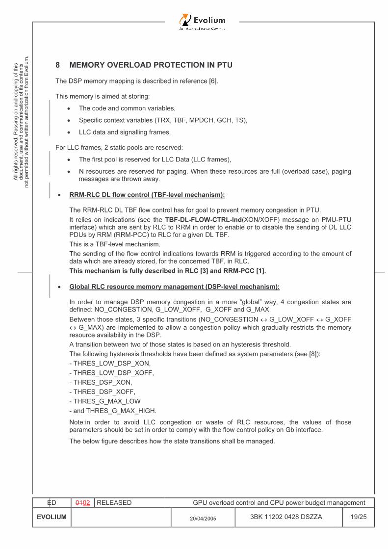
8 MEMORY OVERLOAD PROTECTION IN PTU The DSP memory mapping is described in reference [6]. This memory is aimed at storing:
• The code and common variables, • Specific context variables (TRX, TBF, MPDCH, GCH, TS), • LLC data and signalling frames.
For LLC frames, 2 static pools are reserved: • The first pool is reserved for LLC Data (LLC frames), • N resources are reserved for paging. When these resources are full (overload case), paging
messages are thrown away.
• RRM-RLC DL flow control (TBF-level mechanism): The RRM-RLC DL TBF flow control has for goal to prevent memory congestion in PTU. It relies on indications (see the TBF-DL-FLOW-CTRL-Ind(XON/XOFF) message on PMU-PTU interface) which are sent by RLC to RRM in order to enable or to disable the sending of DL LLC PDUs by RRM (RRM-PCC) to RLC for a given DL TBF. This is a TBF-level mechanism. The sending of the flow control indications towards RRM is triggered according to the amount of data which are already stored, for the concerned TBF, in RLC. This mechanism is fully described in RLC [3] and RRM-PCC [1].
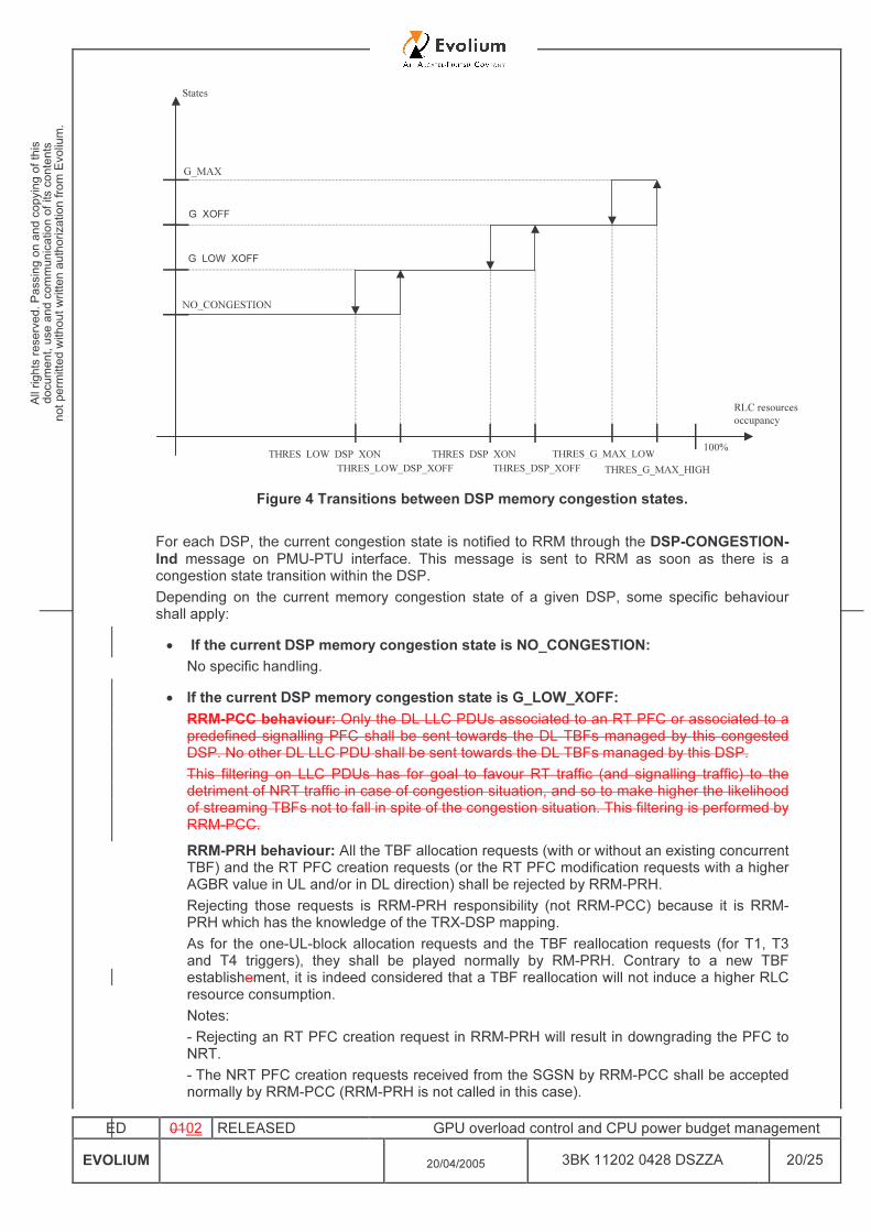
• Global RLC resource memory management (DSP-level mechanism): In order to manage DSP memory congestion in a more “global” way, 4 congestion states are defined: NO_CONGESTION, G_LOW_XOFF, G_XOFF and G_MAX. Between those states, 3 specific transitions (NO_CONGESTION ↔ G_LOW_XOFF ↔ G_XOFF ↔ G_MAX) are implemented to allow a congestion policy which gradually restricts the memory resource availability in the DSP. A transition between two of those states is based on an hysteresis threshold. The following hysteresis thresholds have been defined as system parameters (see [8]): - THRES_LOW_DSP_XON, - THRES_LOW_DSP_XOFF, - THRES_DSP_XON, - THRES_DSP_XOFF, - THRES_G_MAX_LOW - and THRES_G_MAX_HIGH. Note: in order to avoid LLC congestion or waste of RLC resources, the values of those parameters should be set in order to comply with the flow control policy on Gb interface. The below figure describes how the state transitions shall be managed.
ED 0102 RELEASED GPU overload control and CPU power budget management EVOLIUM 20/04/2005 3BK 11202 0428 DSZZA 20/25
RLC resources occupancy
100%G_MAX_HIGH
N_TBF_ONN_TBF_OFF
DSP_XON_THRDSP_XOFF_THR
N_TBF_OFF
G_MAX
G_MAX_LOW
NO_CONGESTION
G_OFF
States
Figure 4 Transitions between DSP memory congestion states.
For each DSP, the current congestion state is notified to RRM through the DSP-CONGESTION-Ind message on PMU-PTU interface. This message is sent to RRM as soon as there is a congestion state transition within the DSP. Depending on the current memory congestion state of a given DSP, some specific behaviour shall apply: • If the current DSP memory congestion state is NO_CONGESTION:
No specific handling. • If the current DSP memory congestion state is G_LOW_XOFF:
RRM-PCC behaviour: Only the DL LLC PDUs associated to an RT PFC or associated to a predefined signalling PFC shall be sent towards the DL TBFs managed by this congested DSP. No other DL LLC PDU shall be sent towards the DL TBFs managed by this DSP. This filtering on LLC PDUs has for goal to favour RT traffic (and signalling traffic) to the detriment of NRT traffic in case of congestion situation, and so to make higher the likelihood of streaming TBFs not to fall in spite of the congestion situation. This filtering is performed by RRM-PCC. RRM-PRH behaviour: All the TBF allocation requests (with or without an existing concurrent TBF) and the RT PFC creation requests (or the RT PFC modification requests with a higher AGBR value in UL and/or in DL direction) shall be rejected by RRM-PRH. Rejecting those requests is RRM-PRH responsibility (not RRM-PCC) because it is RRM-PRH which has the knowledge of the TRX-DSP mapping. As for the one-UL-block allocation requests and the TBF reallocation requests (for T1, T3 and T4 triggers), they shall be played normally by RM-PRH. Contrary to a new TBF establishement, it is indeed considered that a TBF reallocation will not induce a higher RLC resource consumption. Notes: - Rejecting an RT PFC creation request in RRM-PRH will result in downgrading the PFC to NRT. - The NRT PFC creation requests received from the SGSN by RRM-PCC shall be accepted normally by RRM-PCC (RRM-PRH is not called in this case).
G_LOW_XOFF
G_XOFF
THRES_LOW_DSP_XOFF THRES_LOW_DSP_XON
THRES_DSP_XOFF THRES_DSP_XON
THRES_G_MAX_HIGH THRES_G_MAX_LOW
ED 0102 RELEASED GPU overload control and CPU power budget management EVOLIUM 20/04/2005 3BK 11202 0428 DSZZA 21/25
- The streaming TBF establishment requests (associated to an RT PFC which was successfully created in the past) are not rejected (RRM-PRH is not called and RRM-PCC will serve those requests normally). RLC behaviour: contrary to B8 where all the TBF establishment requests were rejected by RLC, no specific behaviour is necessary in B9. Introducing a specific behaviour in B9 in order to only reject the NRT TBF establishment requests, and not the streaming TBF establishment requests (associated to an RT PFC which was successfully created in the past) would be useless because no more NRT TBF establishment request will be sent to RLC once the G_LOW_XOFF state has been notified to RRM. • If the current DSP memory congestion state is G_XOFF: Same behaviour as in the G_LOW_XOFF state, . And, in addition, except that no DL LLC PDUs shall be sent towards the DL TBFs managed by this congested DSP any longer (even the DL LLC PDUs which are associated to an RT PFC or which are associated to a predefined signalling PFC). Note: as a simplification, no distinction is made between the DL LLC PDUs associated to an RT PFC or associated to a predefined signalling PFC, and the lower-priority DL LLC PDUs. • If the current DSP memory congestion state is G_MAX: Same behaviour as in the G_XOFF state. And, in addition, some TBFs shall be autonomously released by the congested DSP so as to free enough RLC resources to enter the G_XOFF state again (cf. THRES_G_MAX_LOW hysteresis threshold). The TBFs to be released shall be selected by the DSP as follows: 1) The NRT TBFs shall be released in priority. 2) In case no (more) NRT TBFs can be released, the streaming TBFs shall then be released. No finer criteria are defined for selecting the TBFs to be released. In particular, for simplification reasons, the scheduling priority of the NRT TBFs is not taken into account (e.g. whether the NRT TBFs are associated to a predefined signalling PFC or not is not taken into account). For each TBF to be released, a TBF-RELEASE-ind message shall be sent by RLC to RRM on PMU-PTU interface.
ED 0102 RELEASED GPU overload control and CPU power budget management EVOLIUM 20/04/2005 3BK 11202 0428 DSZZA 22/25
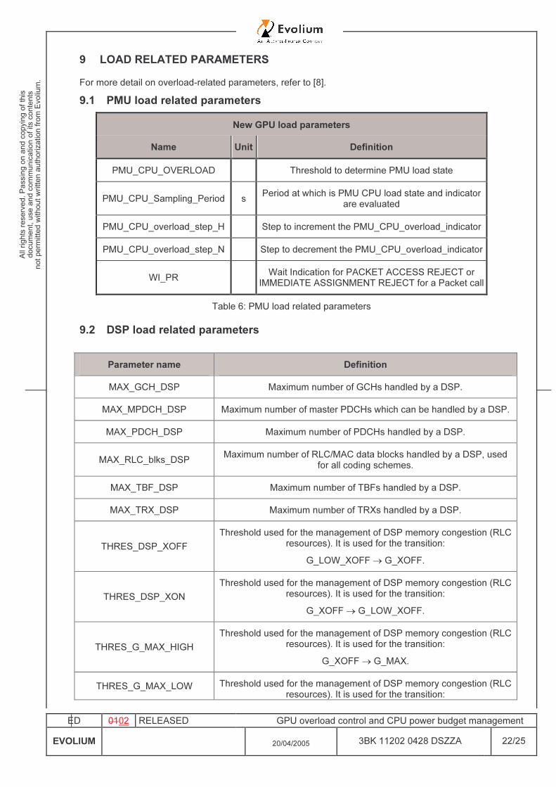
9 LOAD RELATED PARAMETERS For more detail on overload-related parameters, refer to [8]. 9.1 PMU load related parameters
New GPU load parameters Name Unit Definition
PMU_CPU_OVERLOAD Threshold to determine PMU load state
PMU_CPU_Sampling_Period s Period at which is PMU CPU load state and indicator are evaluated
PMU_CPU_overload_step_H Step to increment the PMU_CPU_overload_indicator
PMU_CPU_overload_step_N Step to decrement the PMU_CPU_overload_indicator
WI_PR Wait Indication for PACKET ACCESS REJECT or IMMEDIATE ASSIGNMENT REJECT for a Packet call
Table 6: PMU load related parameters
9.2 DSP load related parameters
Parameter name Definition MAX_GCH_DSP Maximum number of GCHs handled by a DSP.
MAX_MPDCH_DSP Maximum number of master PDCHs which can be handled by a DSP. MAX_PDCH_DSP Maximum number of PDCHs handled by a DSP.
MAX_RLC_blks_DSP Maximum number of RLC/MAC data blocks handled by a DSP, used for all coding schemes.
MAX_TBF_DSP Maximum number of TBFs handled by a DSP. MAX_TRX_DSP Maximum number of TRXs handled by a DSP.
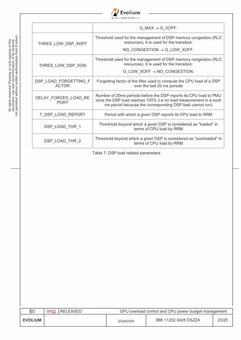
THRES_DSP_XOFF Threshold used for the management of DSP memory congestion (RLC
resources). It is used for the transition: G_LOW_XOFF → G_XOFF.
THRES_DSP_XON Threshold used for the management of DSP memory congestion (RLC
resources). It is used for the transition: G_XOFF → G_LOW_XOFF.
THRES_G_MAX_HIGH Threshold used for the management of DSP memory congestion (RLC
resources). It is used for the transition: G_XOFF → G_MAX.
THRES_G_MAX_LOW Threshold used for the management of DSP memory congestion (RLC resources). It is used for the transition:
ED 0102 RELEASED GPU overload control and CPU power budget management EVOLIUM 20/04/2005 3BK 11202 0428 DSZZA 23/25
G_MAX → G_XOFF.
THRES_LOW_DSP_XOFF Threshold used for the management of DSP memory congestion (RLC
resources). It is used for the transition: NO_CONGESTION → G_LOW_XOFF.
THRES_LOW_DSP_XON Threshold used for the management of DSP memory congestion (RLC
resources). It is used for the transition: G_LOW_XOFF → NO_CONGESTION.
DSP_LOAD_FORGETTING_FACTOR
Forgetting factor of the filter used to compute the CPU load of a DSP over the last 20 ms periods
DELAY_FORCED_LOAD_REPORT
Number of 20ms periods before the DSP reports its CPU load to PMU once the DSP load reaches 100% (i.e no load measurement in a such
ms period because the corresponding DSP task cannot run) T_DSP_LOAD_REPORT Period with which a given DSP reports its CPU load to RRM
DSP_LOAD_THR_1 Threshold beyond which a given DSP is considered as "loaded" in terms of CPU load by RRM
DSP_LOAD_THR_2 Threshold beyond which a given DSP is considered as "overloaded" in terms of CPU load by RRM
Table 7: DSP load related parameters

ED 0102 RELEASED GPU overload control and CPU power budget management EVOLIUM 20/04/2005 3BK 11202 0428 DSZZA 24/25
10 GLOSSARY AND ABBREVIATIONS BSCGP BSC GPRS Part BSC Base Station Controller BSS Base Station System BTS Base Transceiver Station BVC BSSGP Virtual Connection CPU Central Processing Unit CS paging Circuit Switched paging DL DownLink CCCH Common Control Channel DSP Digital Signalling Processor EGPRS Enhanced GPRS GCH GPRS Channel GPRS General Packet Radio Service GPU GPRS Processing Unit GSL GPRS Signalling Link LA Location Area LLC Logical Link Control MAC Medium Access Control MFS Multi BSS Fast packet Server MPDCH Master PDCH MS Mobile Station NS Network Service NSC Network Service Control NSEI Network Service Entity Identifier NSS Network Sub-System NS-VCI Network service - Virtual Connection Identifier NS-VLI Network service - Virtual Link Identifier PACCH Packet Associated Control CHannel PCCCH Packet Common Control Channel PCC Packet Connection Control PCU Packet Control Unit PDCH Packet Data Channel PDU Protocol Data Unit PMU Packet Management Unit PRH Packet Resource Handling PS Packet Switched PSI Packet Sytem Information PS paging Packet Switched paging PVC Permanent Virtual Channel PTU Packet Transfer Unit RA Routeing Area RL ReLay RLC Radio Link Control
ED 0102 RELEASED GPU overload control and CPU power budget management EVOLIUM 20/04/2005 3BK 11202 0428 DSZZA 25/25
RRM Radio Resource Management SGSN Serving GPRS Support Node SPDCH Slave PDCH TAI Timing Advance Index TBF Temporary Block Flow TFI Temporary Flow Identity TLLI Temporary Logical Link Identity TMSI Temporary Mobile Subscriber Identity TRX Transceiver TS Time Slot UL UpLink USF Uplink Status Flag VLR Visitor Location register
END OF DOCUMENT