Embed Size (px)
Citation preview
Troubleshooting Your Designwith the TPS2000B Series

Today’s engineers and technicians face increasingly complex and critical troubleshooting tasks. New digital designs often confront designers with new problems to find: race conditions, transients, signal aberrations, etc. And, of course, competitive time-to-market pressures dictate that troubleshooting must be completed quickly and accurately. These tips are designed to simplify and speed these troubleshooting tasks.
Measure 3-Phase Systems ..................................................................................... 4
Capture Elusive Glitches and Waveform Anomalies – 1/2 ........................................ 5
Capture Elusive Glitches and Waveform Anomalies – 2/2 ........................................ 6
Measure Control Effects on Power Systems ........................................................... 7
Check for Signal Integrity ........................................................................................ 8
Look for Unintentional Circuit Noise ........................................................................ 9
Look at Instantaneous Power Waveforms ............................................................. 10
Make dv/dt and di/dt Cursor Measurements ......................................................... 11
Measure Power Design Switching Losses ............................................................. 12
Look at Phase Relationships ................................................................................. 13
Measure Power Harmonics ................................................................................... 14
Find Control Anomalies in a Widespread Installation ............................................. 15
Save Measurement Results .................................................................................. 16
Transfer Data to a PC ........................................................................................... 17
Waveform Analysis Using NI SignalExpress™ Tektronix Edition Software................ 18
Table of Contents
TPS2000B Series Troubleshooting Tips www.tektronix.com/tps2000b 4
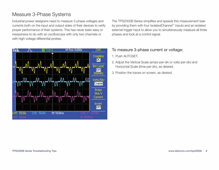
Industrial power designers need to measure 3-phase voltages and currents both on the input and output sides of their devices to verify proper performance of their systems. This has never been easy or inexpensive to do with an oscilloscope with only two channels or with high-voltage differential probes.
The TPS2000B Series simplifies and speeds this measurement task by providing them with four IsolatedChannel™ inputs and an isolated external trigger input to allow you to simultaneously measure all three phases and look at a control signal.
To measure 3-phase current or voltage:
1. Push AUTOSET.
2. Adjust the Vertical Scale (amps-per-div or volts-per-div) and Horizontal Scale (time-per-div), as desired.
3. Position the traces on screen, as desired.
Measure 3-Phase Systems
TPS2000B Series Troubleshooting Tips www.tektronix.com/tps2000b 5
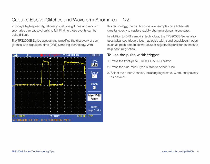
In today’s high-speed digital designs, elusive glitches and random anomalies can cause circuits to fail. Finding these events can be quite difficult.
The TPS2000B Series speeds and simplifies the discovery of such glitches with digital real-time (DRT) sampling technology. With
this technology, the oscilloscope over-samples on all channels simultaneously to capture rapidly changing signals in one pass.
In addition to DRT sampling technology, the TPS2000B Series also uses advanced triggers (such as pulse width) and acquisition modes (such as peak detect) as well as user-adjustable persistence times to help capture glitches.
To use the pulse width trigger:
1. Press the front-panel TRIGGER MENU button.
2. Press the side-menu Type button to select Pulse.
3. Select the other variables, including logic state, width, and polarity, as desired.
Capture Elusive Glitches and Waveform Anomalies – 1/2
TPS2000B Series Troubleshooting Tips www.tektronix.com/tps2000b 6
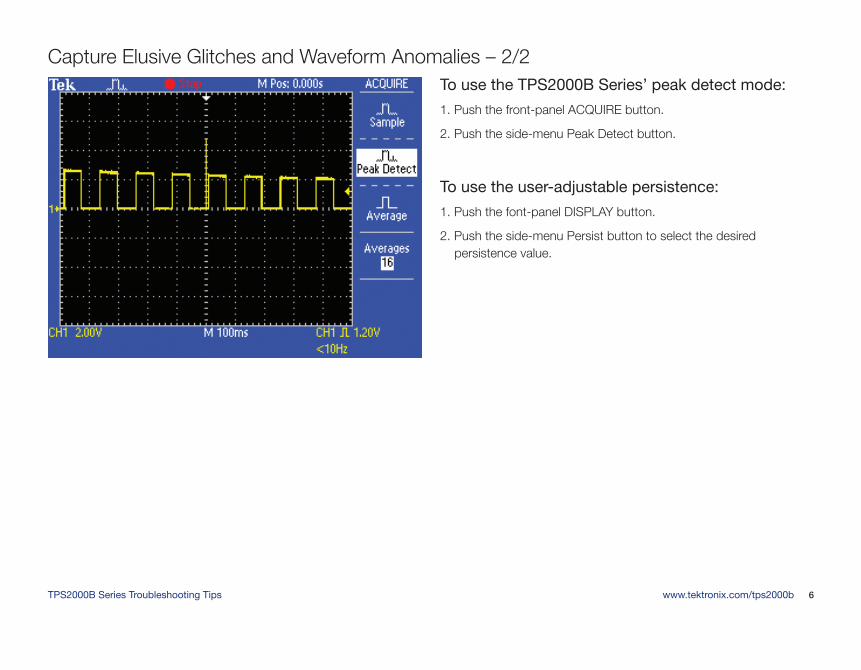
To use the TPS2000B Series’ peak detect mode:
1. Push the front-panel ACQUIRE button.
2. Push the side-menu Peak Detect button.
To use the user-adjustable persistence:
1. Push the font-panel DISPLAY button.
2. Push the side-menu Persist button to select the desired persistence value.
Capture Elusive Glitches and Waveform Anomalies – 2/2
TPS2000B Series Troubleshooting Tips www.tektronix.com/tps2000b 7
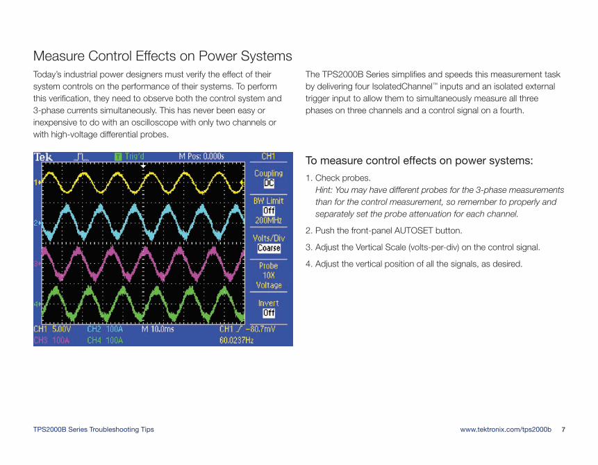
Today’s industrial power designers must verify the effect of their system controls on the performance of their systems. To perform this verification, they need to observe both the control system and 3-phase currents simultaneously. This has never been easy or inexpensive to do with an oscilloscope with only two channels or with high-voltage differential probes.
The TPS2000B Series simplifies and speeds this measurement task by delivering four IsolatedChannel™ inputs and an isolated external trigger input to allow them to simultaneously measure all three phases on three channels and a control signal on a fourth.
To measure control effects on power systems:
1. Check probes. Hint: You may have different probes for the 3-phase measurements than for the control measurement, so remember to properly and separately set the probe attenuation for each channel.
2. Push the front-panel AUTOSET button.
3. Adjust the Vertical Scale (volts-per-div) on the control signal.
4. Adjust the vertical position of all the signals, as desired.
Measure Control Effects on Power Systems
TPS2000B Series Troubleshooting Tips www.tektronix.com/tps2000b 8
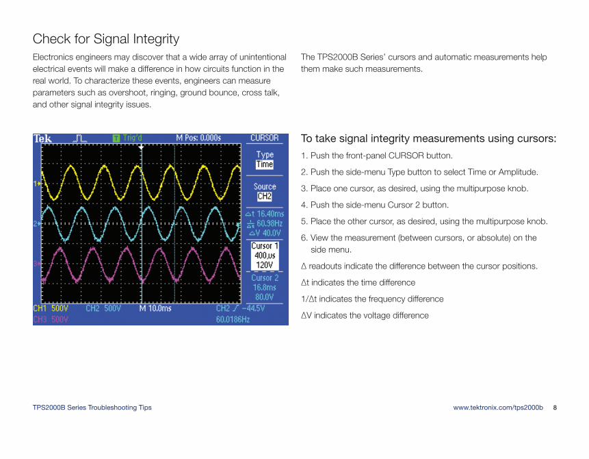
Electronics engineers may discover that a wide array of unintentional electrical events will make a difference in how circuits function in the real world. To characterize these events, engineers can measure parameters such as overshoot, ringing, ground bounce, cross talk, and other signal integrity issues.
The TPS2000B Series’ cursors and automatic measurements help them make such measurements.
To take signal integrity measurements using cursors:
1. Push the front-panel CURSOR button.
2. Push the side-menu Type button to select Time or Amplitude.
3. Place one cursor, as desired, using the multipurpose knob.
4. Push the side-menu Cursor 2 button.
5. Place the other cursor, as desired, using the multipurpose knob.
6. View the measurement (between cursors, or absolute) on the side menu.
Δ readouts indicate the difference between the cursor positions.
Δt indicates the time difference
1/Δt indicates the frequency difference
ΔV indicates the voltage difference
Check for Signal Integrity
TPS2000B Series Troubleshooting Tips www.tektronix.com/tps2000b 9
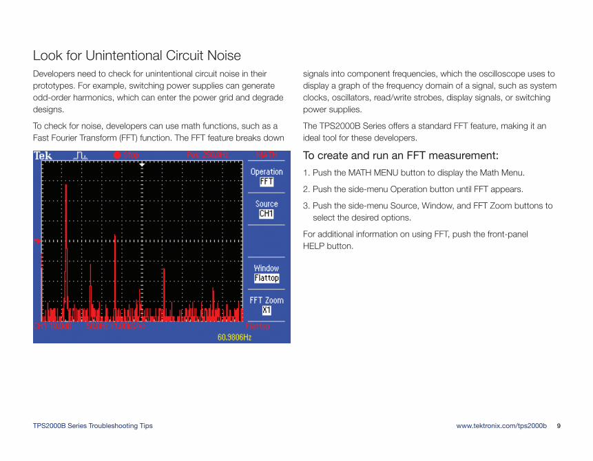
Developers need to check for unintentional circuit noise in their prototypes. For example, switching power supplies can generate odd-order harmonics, which can enter the power grid and degrade designs.
To check for noise, developers can use math functions, such as a Fast Fourier Transform (FFT) function. The FFT feature breaks down
signals into component frequencies, which the oscilloscope uses to display a graph of the frequency domain of a signal, such as system clocks, oscillators, read/write strobes, display signals, or switching power supplies.
The TPS2000B Series offers a standard FFT feature, making it an ideal tool for these developers.
To create and run an FFT measurement:
1. Push the MATH MENU button to display the Math Menu.
2. Push the side-menu Operation button until FFT appears.
3. Push the side-menu Source, Window, and FFT Zoom buttons to select the desired options.
For additional information on using FFT, push the front-panel HELP button.
Look for Unintentional Circuit Noise
TPS2000B Series Troubleshooting Tips www.tektronix.com/tps2000b 10
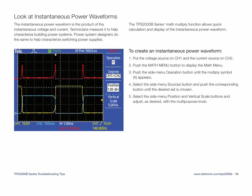
The instantaneous power waveform is the product of the instantaneous voltage and current. Technicians measure it to help characterize building power systems. Power system designers do the same to help characterize switching power supplies.
The TPS2000B Series’ math multiply function allows quick calculation and display of the instantaneous power waveform.
To create an instantaneous power waveform:
1. Put the voltage source on CH1 and the current source on CH2.
2. Push the MATH MENU button to display the Math Menu.
3. Push the side-menu Operation button until the multiply symbol (X) appears.
4. Select the side-menu Sources button and push the corresponding button until the desired set is chosen.
5. Select the side-menu Position and Vertical Scale buttons and adjust, as desired, with the multipurpose knob.
Look at Instantaneous Power Waveforms
TPS2000B Series Troubleshooting Tips www.tektronix.com/tps2000b 11
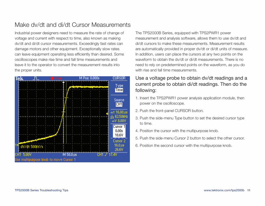
Industrial power designers need to measure the rate of change of voltage and current with respect to time, also known as making dv/dt and di/dt cursor measurements. Exceedingly fast rates can damage motors and other equipment. Exceptionally slow rates can leave equipment operating less efficiently than desired. Some oscilloscopes make rise time and fall time measurements and leave it to the operator to convert the measurement results into the proper units.
The TPS2000B Series, equipped with TPS2PWR1 power measurement and analysis software, allows them to use dv/dt and di/dt cursors to make these measurements. Measurement results are automatically provided in proper dv/dt or di/dt units of measure. In addition, users can place the cursors at any two points on the waveform to obtain the dv/dt or di/dt measurements. There is no need to rely on predetermined points on the waveform, as you do with rise and fall time measurements.
Use a voltage probe to obtain dv/dt readings and a current probe to obtain di/dt readings. Then do the following:
1. Insert the TPS2PWR1 power analysis application module, then power on the oscilloscope.
2. Push the front-panel CURSOR button.
3. Push the side-menu Type button to set the desired cursor type to time.
4. Position the cursor with the multipurpose knob.
5. Push the side-menu Cursor 2 button to select the other cursor.
6. Position the second cursor with the multipurpose knob.
Make dv/dt and di/dt Cursor Measurements
TPS2000B Series Troubleshooting Tips www.tektronix.com/tps2000b 12
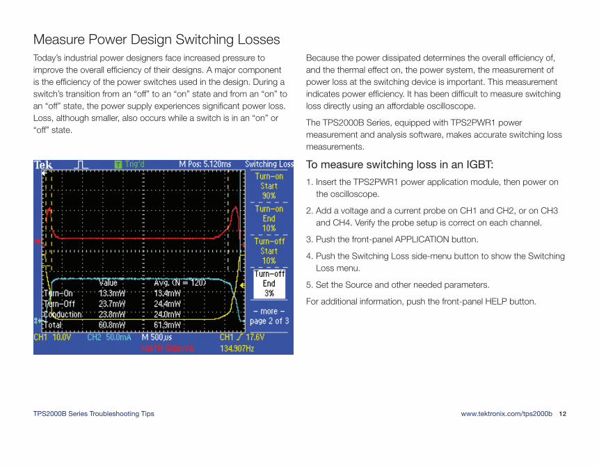
Today’s industrial power designers face increased pressure to improve the overall efficiency of their designs. A major component is the efficiency of the power switches used in the design. During a switch’s transition from an “off” to an “on” state and from an “on” to an “off” state, the power supply experiences significant power loss. Loss, although smaller, also occurs while a switch is in an “on” or “off” state.
Because the power dissipated determines the overall efficiency of, and the thermal effect on, the power system, the measurement of power loss at the switching device is important. This measurement indicates power efficiency. It has been difficult to measure switching loss directly using an affordable oscilloscope.
The TPS2000B Series, equipped with TPS2PWR1 power measurement and analysis software, makes accurate switching loss measurements.
To measure switching loss in an IGBT:
1. Insert the TPS2PWR1 power application module, then power on the oscilloscope.
2. Add a voltage and a current probe on CH1 and CH2, or on CH3 and CH4. Verify the probe setup is correct on each channel.
3. Push the front-panel APPLICATION button.
4. Push the Switching Loss side-menu button to show the Switching Loss menu.
5. Set the Source and other needed parameters.
For additional information, push the front-panel HELP button.
Measure Power Design Switching Losses
TPS2000B Series Troubleshooting Tips www.tektronix.com/tps2000b 13
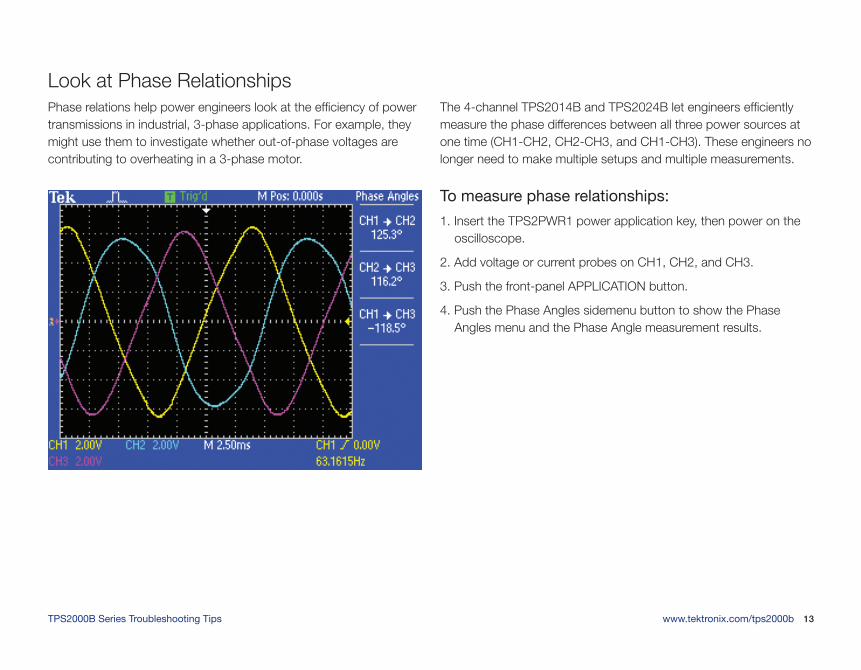
Phase relations help power engineers look at the efficiency of power transmissions in industrial, 3-phase applications. For example, they might use them to investigate whether out-of-phase voltages are contributing to overheating in a 3-phase motor.
The 4-channel TPS2014B and TPS2024B let engineers efficiently measure the phase differences between all three power sources at one time (CH1-CH2, CH2-CH3, and CH1-CH3). These engineers no longer need to make multiple setups and multiple measurements.
To measure phase relationships:
1. Insert the TPS2PWR1 power application key, then power on the oscilloscope.
2. Add voltage or current probes on CH1, CH2, and CH3.
3. Push the front-panel APPLICATION button.
4. Push the Phase Angles sidemenu button to show the Phase Angles menu and the Phase Angle measurement results.
Look at Phase Relationships
TPS2000B Series Troubleshooting Tips www.tektronix.com/tps2000b 14
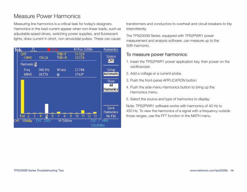
Measuring line harmonics is a critical task for today’s designers. Harmonics in the load current appear when non-linear loads, such as adjustable speed drives, switching power supplies, and fluorescent lights, draw current in short, non-sinusoidal pulses. These can cause
transformers and conductors to overheat and circuit breakers to trip intermittently.
The TPS2000B Series, equipped with TPS2PWR1 power measurement and analysis software, can measure up to the 50th harmonic.
To measure power harmonics:
1. Insert the TPS2PWR1 power application key, then power on the oscilloscope.
2. Add a voltage or a current probe.
3. Push the front-panel APPLICATION button.
4. Push the side-menu Harmonics button to bring up the Harmonics menu.
5. Select the source and type of harmonics to display.
Note: TPS2PWR1 software works with harmonics of 40 Hz to 450 Hz. To view the harmonics of a signal with a frequency outside those ranges, use the FFT function in the MATH menu.
Measure Power Harmonics
TPS2000B Series Troubleshooting Tips www.tektronix.com/tps2000b 15
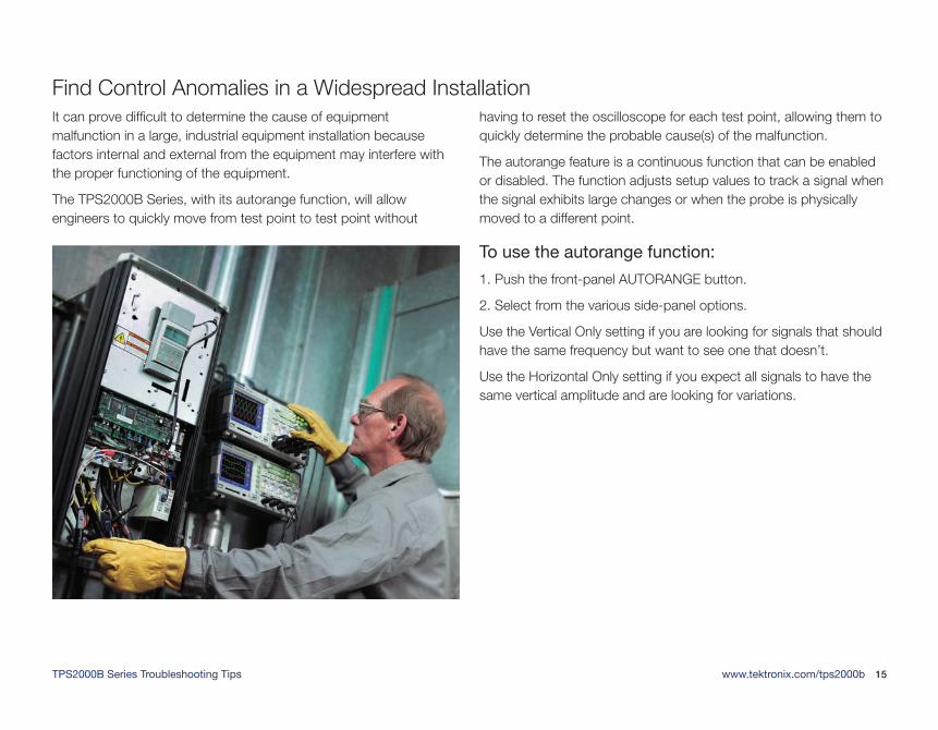
It can prove difficult to determine the cause of equipment malfunction in a large, industrial equipment installation because factors internal and external from the equipment may interfere with the proper functioning of the equipment.
The TPS2000B Series, with its autorange function, will allow engineers to quickly move from test point to test point without
having to reset the oscilloscope for each test point, allowing them to quickly determine the probable cause(s) of the malfunction.
The autorange feature is a continuous function that can be enabled or disabled. The function adjusts setup values to track a signal when the signal exhibits large changes or when the probe is physically moved to a different point.
To use the autorange function:
1. Push the front-panel AUTORANGE button.
2. Select from the various side-panel options.
Use the Vertical Only setting if you are looking for signals that should have the same frequency but want to see one that doesn’t.
Use the Horizontal Only setting if you expect all signals to have the same vertical amplitude and are looking for variations.
Find Control Anomalies in a Widespread Installation
TPS2000B Series Troubleshooting Tips www.tektronix.com/tps2000b 16
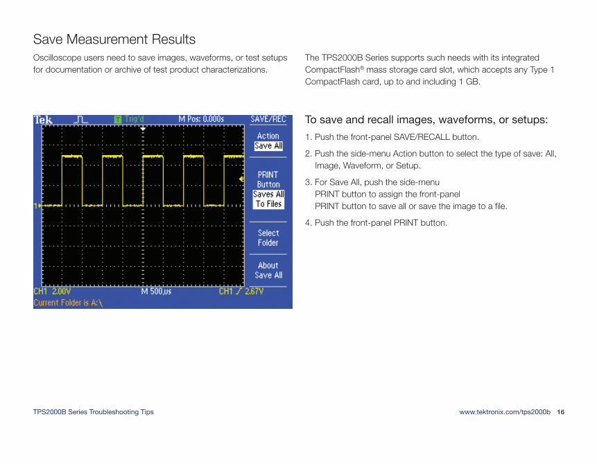
Oscilloscope users need to save images, waveforms, or test setups for documentation or archive of test product characterizations.
The TPS2000B Series supports such needs with its integrated CompactFlash® mass storage card slot, which accepts any Type 1 CompactFlash card, up to and including 1 GB.
To save and recall images, waveforms, or setups:
1. Push the front-panel SAVE/RECALL button.
2. Push the side-menu Action button to select the type of save: All, Image, Waveform, or Setup.
3. For Save All, push the side-menu PRINT button to assign the front-panel PRINT button to save all or save the image to a file.
4. Push the front-panel PRINT button.
Save Measurement Results
TPS2000B Series Troubleshooting Tips www.tektronix.com/tps2000b 17
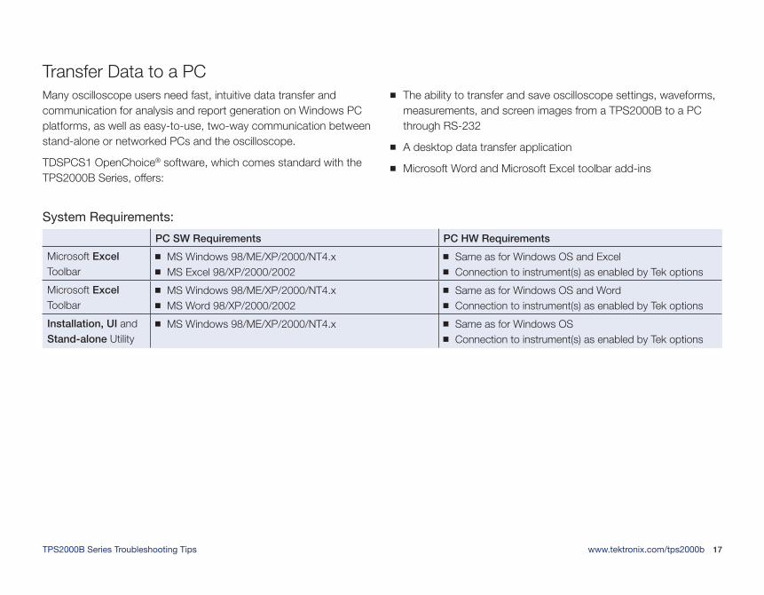
Many oscilloscope users need fast, intuitive data transfer and communication for analysis and report generation on Windows PC platforms, as well as easy-to-use, two-way communication between stand-alone or networked PCs and the oscilloscope.
TDSPCS1 OpenChoice® software, which comes standard with the TPS2000B Series, offers:
The ability to transfer and save oscilloscope settings, waveforms, measurements, and screen images from a TPS2000B to a PC through RS-232
A desktop data transfer application
Microsoft Word and Microsoft Excel toolbar add-ins
Transfer Data to a PC
System Requirements:
PC SW Requirements PC HW Requirements
Microsoft Excel Toolbar
MS Windows 98/ME/XP/2000/NT4.x MS Excel 98/XP/2000/2002
Same as for Windows OS and Excel Connection to instrument(s) as enabled by Tek options
Microsoft Excel Toolbar
MS Windows 98/ME/XP/2000/NT4.x MS Word 98/XP/2000/2002
Same as for Windows OS and Word Connection to instrument(s) as enabled by Tek options
Installation, UI and Stand-alone Utility
MS Windows 98/ME/XP/2000/NT4.x Same as for Windows OS Connection to instrument(s) as enabled by Tek options
TPS2000B Series Troubleshooting Tips www.tektronix.com/tps2000b 18
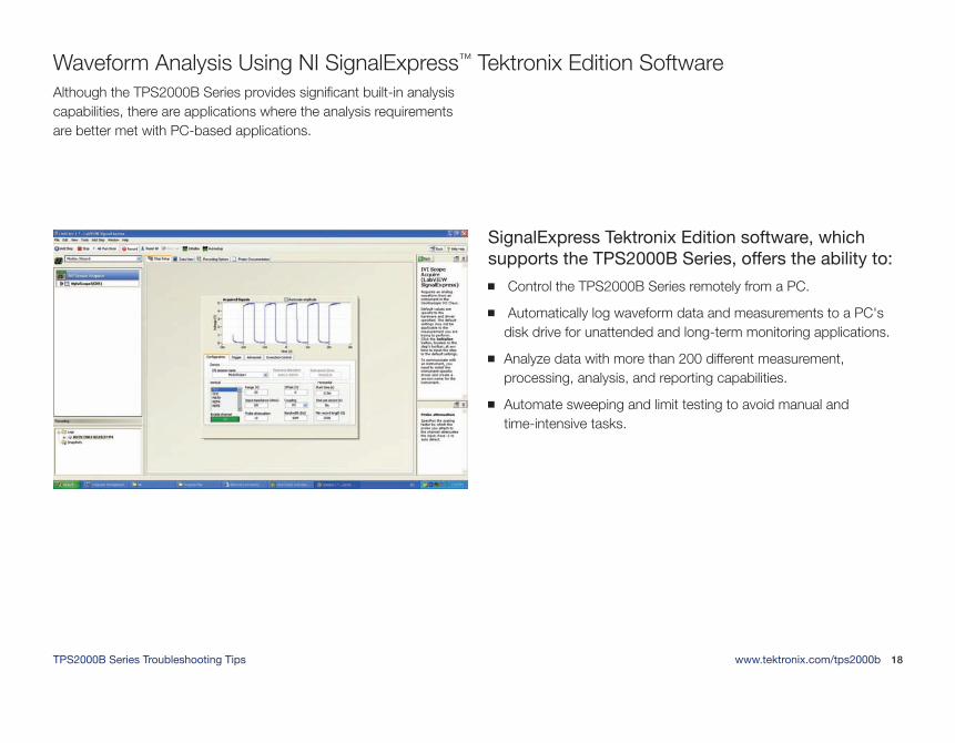
Although the TPS2000B Series provides significant built-in analysis capabilities, there are applications where the analysis requirements are better met with PC-based applications.
SignalExpress Tektronix Edition software, which supports the TPS2000B Series, offers the ability to:
Control the TPS2000B Series remotely from a PC.
Automatically log waveform data and measurements to a PC's disk drive for unattended and long-term monitoring applications.
Analyze data with more than 200 different measurement, processing, analysis, and reporting capabilities.
Automate sweeping and limit testing to avoid manual and time-intensive tasks.
Waveform Analysis Using NI SignalExpress™ Tektronix Edition Software

Copyright © 2011, Tektronix. All rights reserved. Tektronix products are covered by U.S. and foreign patents, issued and pending. Information in this publication supersedes that in all previously published material. Specification and price change privileges reserved. TEKTRONIX and TEK are registered trademarks of Tektronix, Inc. All other trade names referenced are the service marks, trademarks or registered trademarks of their respective companies.
03/11 EA/POD 3MW-17783-1
Contact Tektronix:ASEAN / Australasia (65) 6356 3900Austria* 00800 2255 4835Balkans, Israel, South Africa and other ISE Countries +41 52 675 3777Belgium* 00800 2255 4835Brazil +55 (11) 3759 7627Canada 1 (800) 833-9200Central East Europe and the Baltics +41 52 675 3777Central Europe & Greece +41 52 675 3777Denmark +45 80 88 1401Finland +41 52 675 3777France* 00800 2255 4835Germany* 00800 2255 4835Hong Kong 400-820-5835India 000-800-650-1835Italy* 00800 2255 4835Japan 81 (3) 6714-3010Luxembourg +41 52 675 3777Mexico, Central/South America & Caribbean 52 (55) 56 04 50 90Middle East, Asia and North Africa +41 52 675 3777The Netherlands* 00800 2255 4835Norway 800 16098People’s Republic of China 400-820-5835Poland +41 52 675 3777Portugal 80 08 12370Republic of Korea 001-800-8255-2835Russia & CIS +7 (495) 7484900South Africa +27 11 206 8360Spain* 00800 2255 4835Sweden* 00800 2255 4835Switzerland* 00800 2255 4835Taiwan 886 (2) 2722-9622 United Kingdom & Ireland* 00800 2255 4835USA 1 (800) 833-9200* If the European phone number above is not accessible, please call: +41 52 675 3777
Contact List Updated 10 February 2011