Embed Size (px)
Citation preview

SAFETY.CAT.COM
345B SERIES II and 345BL SERIES II EXCAVATORS Maintenance Intervals
Excerpted from Operation & Maintenance Manual (SEBU7367-02-01)
© 2007 CaterpillarAll Rights Reserved
119Maintenance Section
Maintenance Interval Schedule
i01999931
Maintenance Interval ScheduleSMCS Code: 7000
All safety information, warnings, and instructionsmust be read and understood before you performany operation or any maintenance procedure.
Before each consecutive interval is performed, allof the maintenance requirements from the previousinterval must also be performed.
Refer to Operation and Maintenance Manual,“Hydraulic System Oil - Change” for information ona 4000 hour maintenance interval for the hydraulicsystem.
When Required
Air Conditioner/Cab Heater Filter (Recirculation) -Inspect/Replace ................................................ 121
Battery - Recycle ................................................ 121Battery or Battery Cable - Inspect/Replace ........ 122Boom Base Pins - Lubricate ............................... 123Bucket Linkage - Inspect/Adjust .......................... 125Bucket Tips - Inspect/Replace ............................ 126Circuit Breakers - Reset ...................................... 127Counterweight Removal Chain - Inspect/Clean/Lubricate ........................................................... 133
Engine Air Filter Primary Element -Clean/Replace .................................................. 134
Engine Air Filter Secondary Element - Replace .. 135Engine Air Precleaner - Clean ............................ 136Ether Starting Aid Cylinder - Replace ................. 141Fuses - Replace .................................................. 147Oil Filter - Inspect ................................................ 162Radiator Core - Clean ......................................... 162Screen (Fuel Transfer Pump) - Clean ................. 163Track Adjustment - Adjust ................................... 169Window Washer Reservoir - Fill .......................... 171Window Wiper - Inspect/Replace ........................ 171Windows - Clean ................................................. 172
Every 10 Service Hours or Daily for First 100Hours
Boom, Stick and Bucket Linkage - Lubricate ...... 123
Every 10 Service Hours or Daily
Cooling System Coolant Level - Check .............. 130Engine Oil Level - Check .................................... 137Fuel System Water Separator - Drain ................. 145Fuel Tank Water and Sediment - Drain ............... 146Fuel Tank Water and Sediment - Drain ............... 146Hydraulic System Oil Level - Check .................... 160Indicators and Gauges - Test .............................. 161Seat Belt - Inspect .............................................. 164Track Adjustment - Inspect .................................. 170Travel Alarm - Test .............................................. 170
Undercarriage - Check ........................................ 171
Every 10 Service Hours or Daily for MachinesUsed in Severe Applications
Boom, Stick and Bucket Linkage - Lubricate ...... 123
Every 50 Service Hours or Weekly
Boom, Stick and Bucket Linkage - Lubricate ...... 123
Every 100 Service Hours or 2 Weeks forMachines Used in Severe Applications
Engine Oil and Filter - Change ........................... 138Hydraulic System Oil Filter - Replace ................. 157
Initial 250 Service Hours
Engine Valve Lash and Fuel Injector Timing -Check ................................................................ 140
Final Drive Oil - Change ..................................... 141Hydraulic System Oil Filter (Return) - Replace ... 153Hydraulic System Oil Filter - Replace ................. 157Swing Drive Oil - Change ................................... 165
Every 250 Service Hours
Engine Oil Sample - Obtain ................................ 138Final Drive Oil Sample - Obtain .......................... 142
Every 250 Service Hours or Monthly
Belt - Inspect/Adjust/Replace .............................. 122Condenser (Refrigerant) - Clean ........................ 128Cooling System Hoses - Inspect ......................... 133Engine Oil and Filter - Change ........................... 138Final Drive Oil Level - Check ............................... 142Fuel System Primary Filter - Replace ................. 143Fuel System Secondary Filter - Replace ............ 144Swing Bearing - Lubricate .................................. 164Swing Drive Oil Level - Check ............................. 166
Every 250 Service Hours of Partial HammerUse (50% of Service Hours)
Hydraulic System Oil Filter - Replace ................. 157
Every 250 Service Hours of ContinuousHammer Use
Hydraulic System Oil Filter (Return) - Replace ... 153
Initial 500 Hours (for New Systems, RefilledSystems, and Converted Systems)
Cooling System Coolant Sample (Level 2) -Obtain ............................................................... 132
Every 500 Service Hours
Cooling System Coolant Sample (Level 1) -Obtain ............................................................... 131
120Maintenance SectionMaintenance Interval Schedule
Hydraulic System Oil Sample - Obtain ............... 161Swing Drive Oil Sample - Obtain ........................ 167
Every 500 Service Hours or 3 Months
Engine Crankcase Breather - Clean ................... 136Fuel System - Prime ........................................... 143Fuel Tank Cap and Strainer - Clean ................... 145
Every 500 Service Hours of Partial HammerUse (50% of Service Hours)
Hydraulic System Oil Filter (Return) - Replace ... 153
Every 600 Service Hours of ContinuousHammer Use
Hydraulic System Oil - Change ........................... 148
Every 1000 Service Hours or 6 Months
Battery - Clean .................................................... 121Battery Hold-Down - Tighten .............................. 121Hydraulic System Oil Filter (Return) - Replace ... 153Hydraulic System Oil Filter - Replace ................. 157Swing Drive Oil - Change ................................... 165
Every 1000 Service Hours of Partial HammerUse (50% of Service Hours)
Hydraulic System Oil - Change ........................... 148
Every 2000 Service Hours or 1 Year
Engine Valve Lash and Fuel Injector Timing -Check ................................................................ 140
Engine Valve Rotators - Inspect .......................... 140Final Drive Oil - Change ..................................... 141Hydraulic System Oil - Change ........................... 148Refrigerant Dryer - Replace ................................ 163Swing Gear - Lubricate ....................................... 167
Every Year
Cooling System Coolant Sample (Level 2) -Obtain ............................................................... 132
Every 3 Years After Date of Installation orEvery 5 Years After Date of Manufacture
Seat Belt - Replace ............................................. 164
Every 4000 Service Hours or 2 Years
Hydraulic System Oil - Change ........................... 148
Every 6000 Service Hours or 3 Years
Cooling System Coolant Extender (ELC) - Add .. 129
Every 12 000 Service Hours or 6 Years
Cooling System Coolant (ELC) - Change ........... 128
121Maintenance Section
Air Conditioner/Cab Heater Filter (Recirculation) - Inspect/Replace
i01970040
Air Conditioner/Cab HeaterFilter (Recirculation) -Inspect/ReplaceSMCS Code: 1054-040-A/C; 1054-510-A/C
NOTICEAn air recirculation filter element plugged with dust willresult in decreased performance and service life to theair conditioner or cab heater.
To prevent decreased performance, clean the filter el-ement, as required.
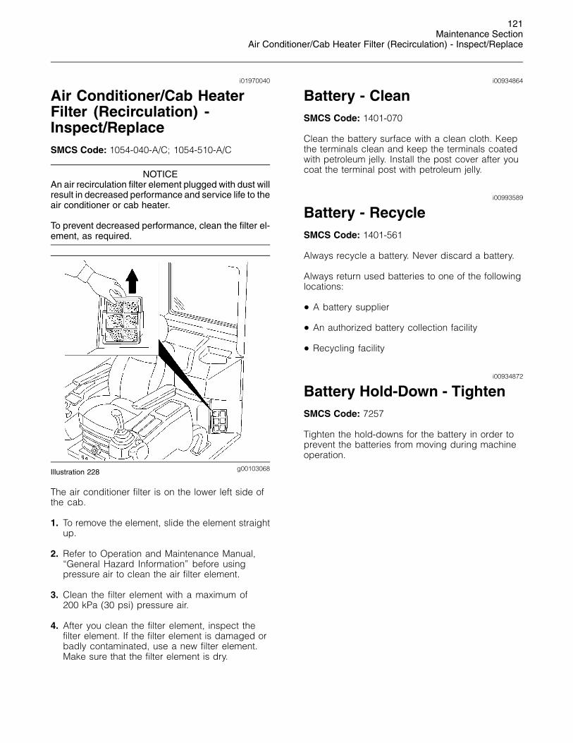
g00103068Illustration 228
The air conditioner filter is on the lower left side ofthe cab.
1. To remove the element, slide the element straightup.
2. Refer to Operation and Maintenance Manual,“General Hazard Information” before usingpressure air to clean the air filter element.
3. Clean the filter element with a maximum of200 kPa (30 psi) pressure air.
4. After you clean the filter element, inspect thefilter element. If the filter element is damaged orbadly contaminated, use a new filter element.Make sure that the filter element is dry.
i00934864
Battery - CleanSMCS Code: 1401-070
Clean the battery surface with a clean cloth. Keepthe terminals clean and keep the terminals coatedwith petroleum jelly. Install the post cover after youcoat the terminal post with petroleum jelly.
i00993589
Battery - RecycleSMCS Code: 1401-561
Always recycle a battery. Never discard a battery.
Always return used batteries to one of the followinglocations:
• A battery supplier
• An authorized battery collection facility
• Recycling facility
i00934872
Battery Hold-Down - TightenSMCS Code: 7257
Tighten the hold-downs for the battery in order toprevent the batteries from moving during machineoperation.
122Maintenance SectionBattery or Battery Cable - Inspect/Replace
i01913589
Battery or Battery Cable -Inspect/ReplaceSMCS Code: 1401-040; 1401-510; 1401-561; 1401;
1402-040; 1402-510
Personal injury can result from battery fumes orexplosion.
Batteries give off flammable fumes that can ex-plode. Electrolyte is an acid and can cause per-sonal injury if it contacts the skin or eyes.
Prevent sparks near the batteries. Sparks couldcause vapors to explode. Do not allow jumper ca-ble ends to contact each other or the engine. Im-proper jumper cable connections can cause an ex-plosion.
Always wear protective glasses when workingwith batteries.
1. Turn the engine start switch key to the OFFposition. Turn all of the switches to the OFFposition.
2. Turn the battery disconnect switch to the OFFposition. Remove the key.
3. Disconnect the negative battery cable at thebattery.
4. Disconnect the positive battery cable at thebattery.
5. Disconnect the battery cables at the batterydisconnect switch. The battery disconnect switchis connected to the machine frame.
6. Make necessary repairs or replace the battery.
7. Connect the battery cable at the batterydisconnect switch.
8. Connect the positive battery cable of the battery.
9. Connect the negative battery cable of the battery.
10. Install the key and turn the battery disconnectswitch to the ON position.
i01961862
Belt - Inspect/Adjust/ReplaceSMCS Code: 1357-025; 1357-040; 1357-510;
1397-025; 1397-040; 1397-510
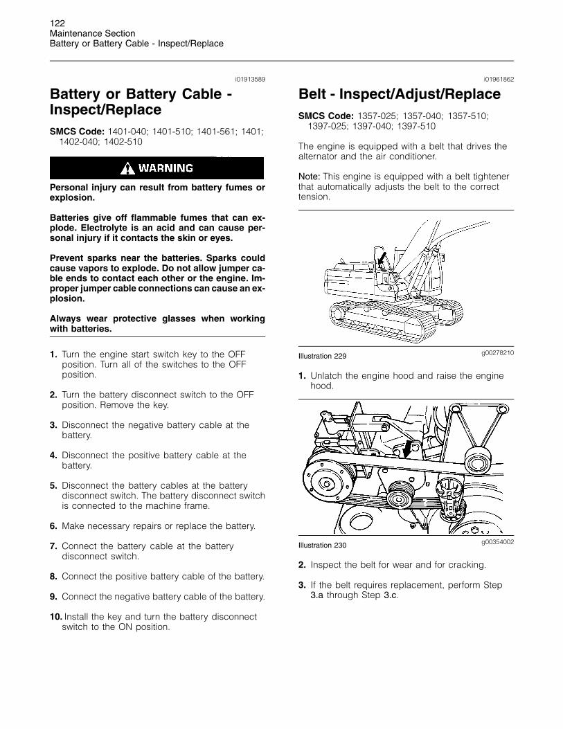
The engine is equipped with a belt that drives thealternator and the air conditioner.
Note: This engine is equipped with a belt tightenerthat automatically adjusts the belt to the correcttension.
g00278210Illustration 229
1. Unlatch the engine hood and raise the enginehood.
g00354002Illustration 230
2. Inspect the belt for wear and for cracking.
3. If the belt requires replacement, perform Step3.a through Step 3.c.
123Maintenance Section
Boom Base Pins - Lubricate
g00354004Illustration 231
a. Turn the belt tensioner in order to release thetension from the belt.
b. Remove the belt.
c. Install a new belt.
Close the engine hood and latch the engine hood.
i01953656
Boom Base Pins - LubricateSMCS Code: 6501-086
Note: Caterpillar recommends the use of 5%molybdenum grease for lubricating the boomlinkage. Refer to Special Publication, SEBU6250,“Caterpillar Machine Fluids Recommendations” formore information on molybdenum grease.
When the boom pin is replaced, lubricate the newboom pin.
g00102767Illustration 232
1. Park the machine on a level surface and lowerthe bucket to the ground.
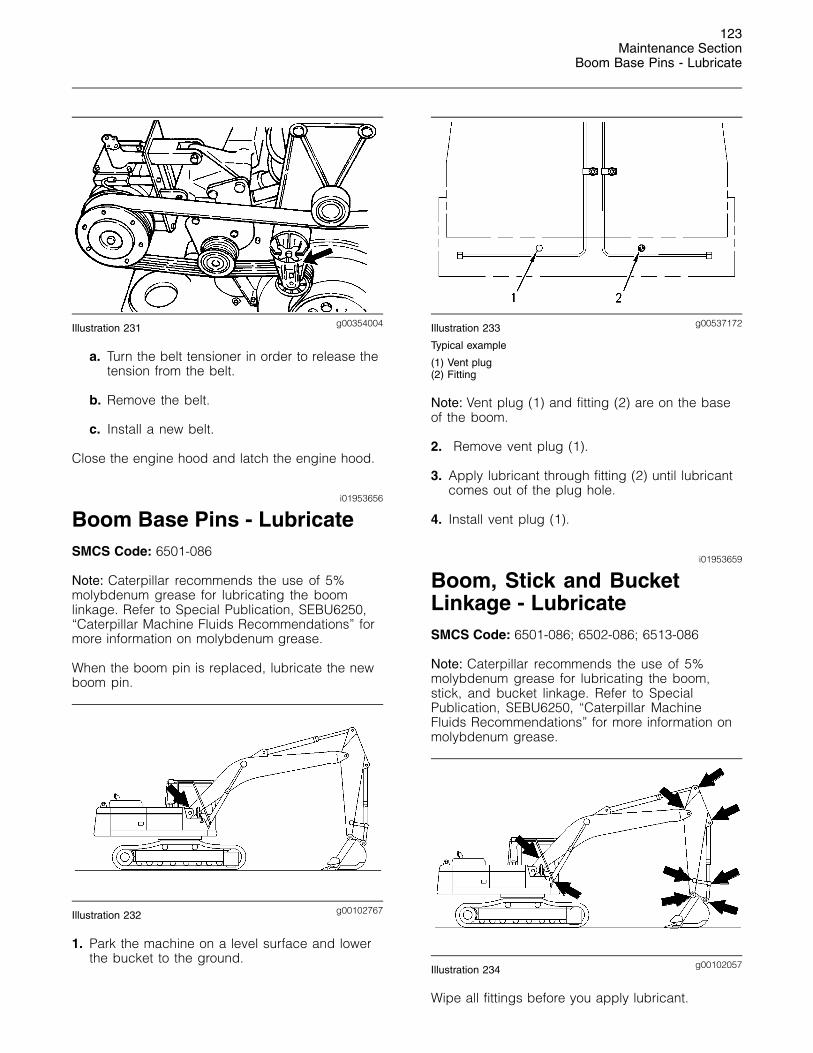
g00537172Illustration 233
Typical example
(1) Vent plug(2) Fitting
Note: Vent plug (1) and fitting (2) are on the baseof the boom.
2. Remove vent plug (1).
3. Apply lubricant through fitting (2) until lubricantcomes out of the plug hole.
4. Install vent plug (1).
i01953659
Boom, Stick and BucketLinkage - LubricateSMCS Code: 6501-086; 6502-086; 6513-086
Note: Caterpillar recommends the use of 5%molybdenum grease for lubricating the boom,stick, and bucket linkage. Refer to SpecialPublication, SEBU6250, “Caterpillar MachineFluids Recommendations” for more information onmolybdenum grease.
g00102057Illustration 234
Wipe all fittings before you apply lubricant.
124Maintenance SectionBoom, Stick and Bucket Linkage - Lubricate
g00359772Illustration 235
1. Apply lubricant through the fitting at the baseof each boom cylinder.
g00359814Illustration 236
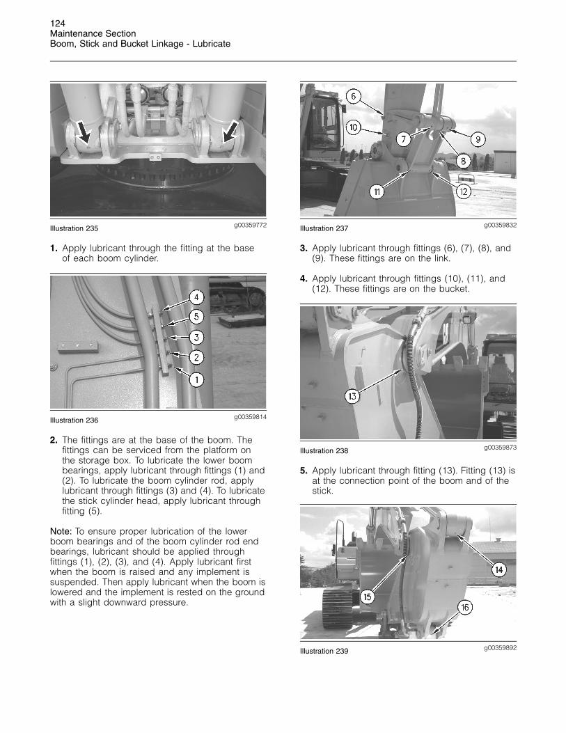
2. The fittings are at the base of the boom. Thefittings can be serviced from the platform onthe storage box. To lubricate the lower boombearings, apply lubricant through fittings (1) and(2). To lubricate the boom cylinder rod, applylubricant through fittings (3) and (4). To lubricatethe stick cylinder head, apply lubricant throughfitting (5).
Note: To ensure proper lubrication of the lowerboom bearings and of the boom cylinder rod endbearings, lubricant should be applied throughfittings (1), (2), (3), and (4). Apply lubricant firstwhen the boom is raised and any implement issuspended. Then apply lubricant when the boom islowered and the implement is rested on the groundwith a slight downward pressure.
g00359832Illustration 237
3. Apply lubricant through fittings (6), (7), (8), and(9). These fittings are on the link.
4. Apply lubricant through fittings (10), (11), and(12). These fittings are on the bucket.
g00359873Illustration 238
5. Apply lubricant through fitting (13). Fitting (13) isat the connection point of the boom and of thestick.
g00359892Illustration 239
125Maintenance Section
Bucket Linkage - Inspect/Adjust
6. Apply lubricant through fitting (14) on the stickcylinder rod. Apply lubricant through fitting (15).Fitting (15) is at the connection point of the boomand of the stick. Apply lubricant through fitting(16) on the bucket cylinder head end.
i01987670
Bucket Linkage -Inspect/AdjustSMCS Code: 6513-025; 6513-040
Unexpected machine movement can cause injuryor death.
To avoid possible machine movement, move thehydraulic lockout control to the locked positionand attach a Special Instruction, SEHS7332, “DoNot Operate” or similar warning tag to the hy-draulic lockout control.
NOTICEImproperly adjusted bucket clearance could causegalling on the contact surfaces of the bucket and stick,resulting in excessive noise and/or damaged O-ringseals.
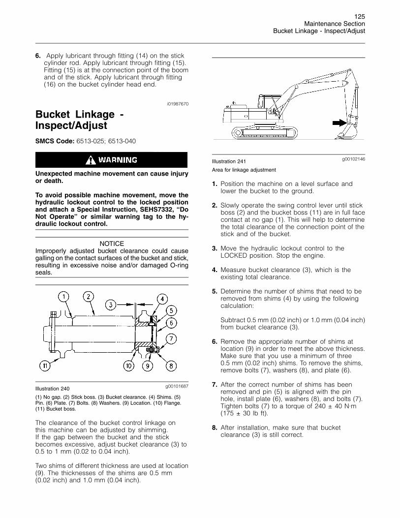
g00101687Illustration 240
(1) No gap. (2) Stick boss. (3) Bucket clearance. (4) Shims. (5)Pin. (6) Plate. (7) Bolts. (8) Washers. (9) Location. (10) Flange.(11) Bucket boss.
The clearance of the bucket control linkage onthis machine can be adjusted by shimming.If the gap between the bucket and the stickbecomes excessive, adjust bucket clearance (3) to0.5 to 1 mm (0.02 to 0.04 inch).
Two shims of different thickness are used at location(9). The thicknesses of the shims are 0.5 mm(0.02 inch) and 1.0 mm (0.04 inch).
g00102146Illustration 241
Area for linkage adjustment
1. Position the machine on a level surface andlower the bucket to the ground.
2. Slowly operate the swing control lever until stickboss (2) and the bucket boss (11) are in full facecontact at no gap (1). This will help to determinethe total clearance of the connection point of thestick and of the bucket.
3. Move the hydraulic lockout control to theLOCKED position. Stop the engine.
4. Measure bucket clearance (3), which is theexisting total clearance.
5. Determine the number of shims that need to beremoved from shims (4) by using the followingcalculation:
Subtract 0.5 mm (0.02 inch) or 1.0 mm (0.04 inch)from bucket clearance (3).
6. Remove the appropriate number of shims atlocation (9) in order to meet the above thickness.Make sure that you use a minimum of three0.5 mm (0.02 inch) shims. To remove the shims,remove bolts (7), washers (8), and plate (6).
7. After the correct number of shims has beenremoved and pin (5) is aligned with the pinhole, install plate (6), washers (8), and bolts (7).Tighten bolts (7) to a torque of 240 ± 40 N·m(175 ± 30 lb ft).
8. After installation, make sure that bucketclearance (3) is still correct.
126Maintenance SectionBucket Tips - Inspect/Replace
i01309815
Bucket Tips - Inspect/ReplaceSMCS Code: 6805-040; 6805-510
Block the bucket before changing the bucketteeth.
To prevent possible injury to the eyes, wear a pro-tective face shield when striking the pin.
The pin, when struck, can fly out and cause injuryto nearby personnel.
Bucket Tips
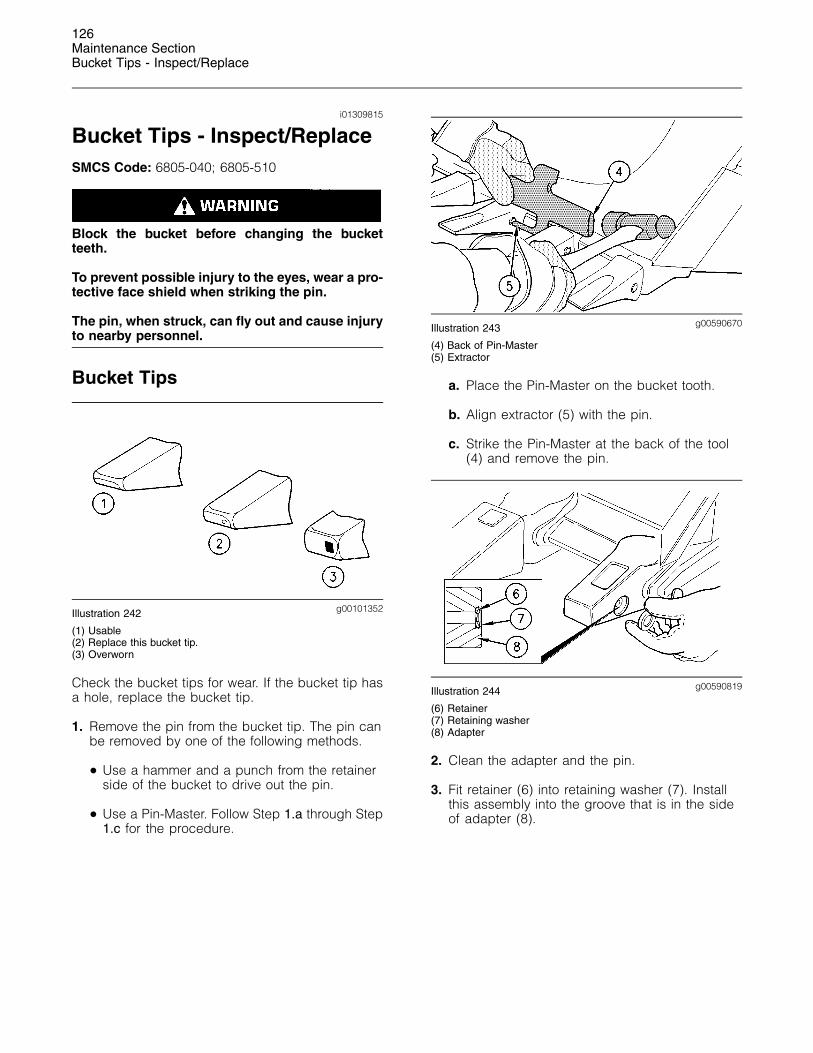
g00101352Illustration 242
(1) Usable(2) Replace this bucket tip.(3) Overworn
Check the bucket tips for wear. If the bucket tip hasa hole, replace the bucket tip.
1. Remove the pin from the bucket tip. The pin canbe removed by one of the following methods.
• Use a hammer and a punch from the retainerside of the bucket to drive out the pin.
• Use a Pin-Master. Follow Step 1.a through Step1.c for the procedure.
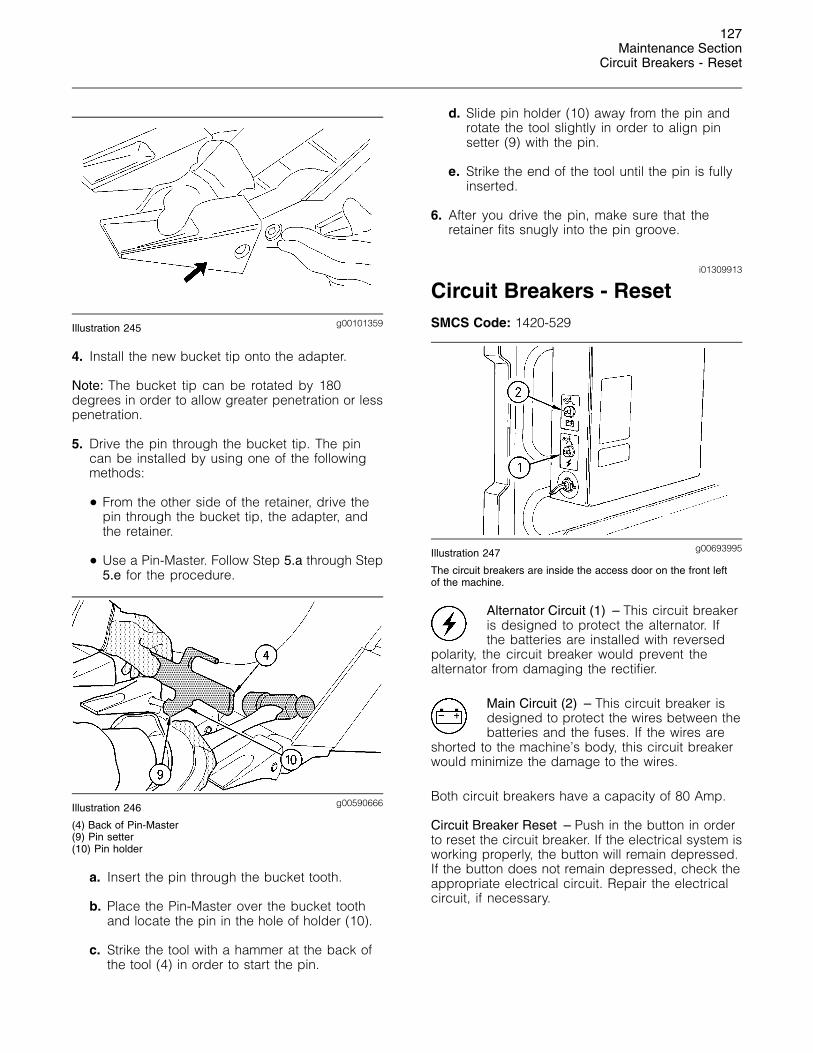
g00590670Illustration 243
(4) Back of Pin-Master(5) Extractor
a. Place the Pin-Master on the bucket tooth.
b. Align extractor (5) with the pin.
c. Strike the Pin-Master at the back of the tool(4) and remove the pin.
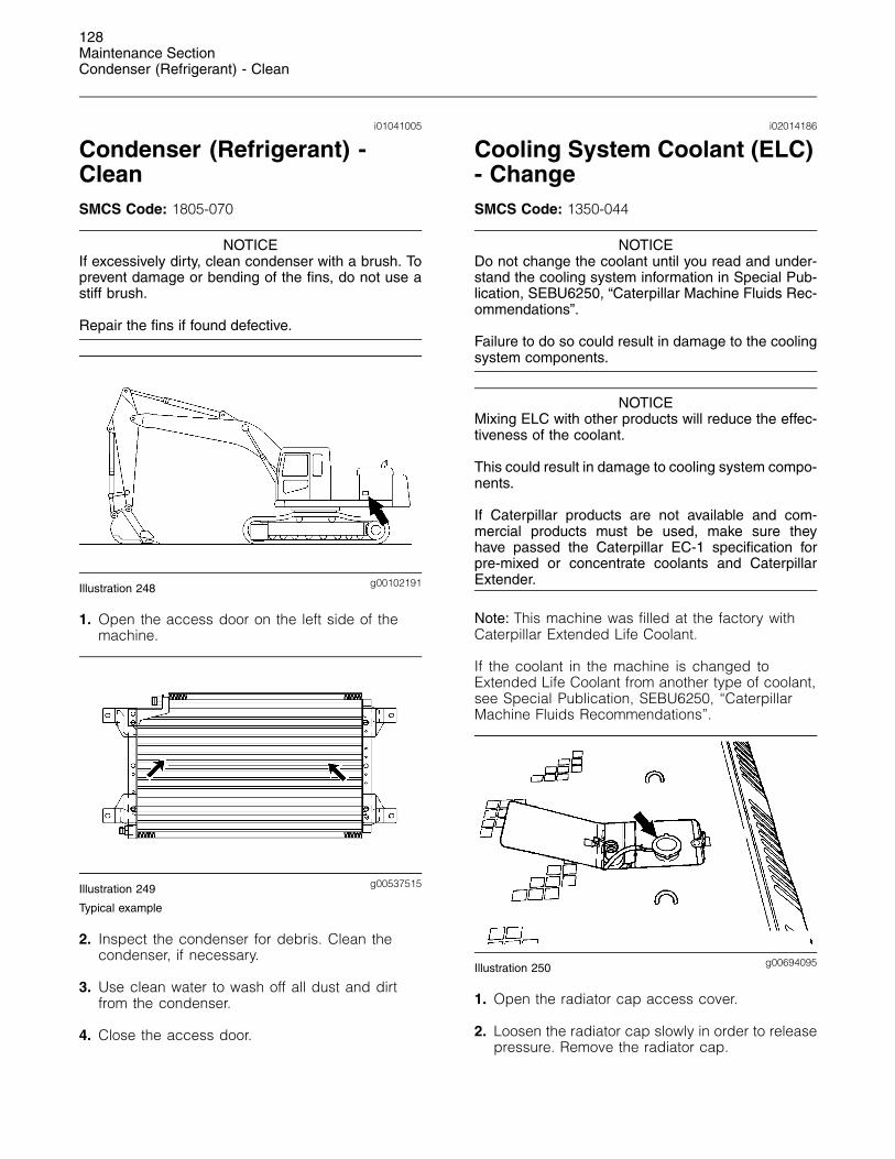
g00590819Illustration 244
(6) Retainer(7) Retaining washer(8) Adapter
2. Clean the adapter and the pin.
3. Fit retainer (6) into retaining washer (7). Installthis assembly into the groove that is in the sideof adapter (8).
127Maintenance Section
Circuit Breakers - Reset
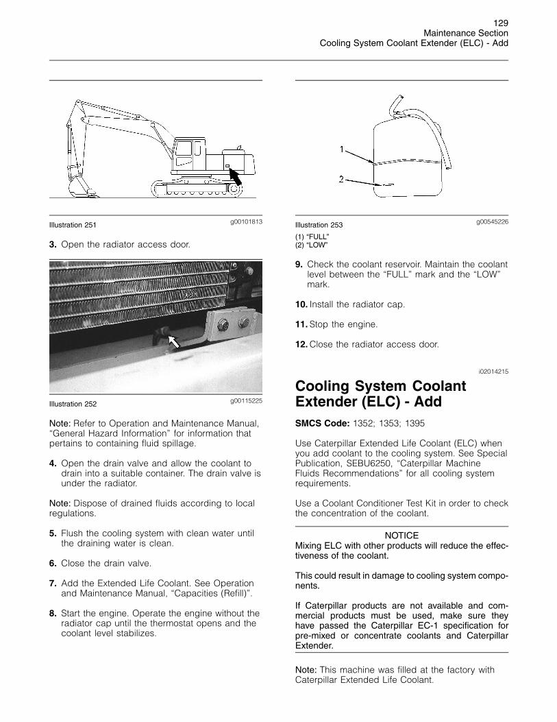
g00101359Illustration 245
4. Install the new bucket tip onto the adapter.
Note: The bucket tip can be rotated by 180degrees in order to allow greater penetration or lesspenetration.
5. Drive the pin through the bucket tip. The pincan be installed by using one of the followingmethods:
• From the other side of the retainer, drive thepin through the bucket tip, the adapter, andthe retainer.
• Use a Pin-Master. Follow Step 5.a through Step5.e for the procedure.
g00590666Illustration 246
(4) Back of Pin-Master(9) Pin setter(10) Pin holder
a. Insert the pin through the bucket tooth.
b. Place the Pin-Master over the bucket toothand locate the pin in the hole of holder (10).
c. Strike the tool with a hammer at the back ofthe tool (4) in order to start the pin.
d. Slide pin holder (10) away from the pin androtate the tool slightly in order to align pinsetter (9) with the pin.
e. Strike the end of the tool until the pin is fullyinserted.
6. After you drive the pin, make sure that theretainer fits snugly into the pin groove.
i01309913
Circuit Breakers - ResetSMCS Code: 1420-529
g00693995Illustration 247
The circuit breakers are inside the access door on the front leftof the machine.
Alternator Circuit (1) – This circuit breakeris designed to protect the alternator. Ifthe batteries are installed with reversed
polarity, the circuit breaker would prevent thealternator from damaging the rectifier.
Main Circuit (2) – This circuit breaker isdesigned to protect the wires between thebatteries and the fuses. If the wires are
shorted to the machine’s body, this circuit breakerwould minimize the damage to the wires.
Both circuit breakers have a capacity of 80 Amp.
Circuit Breaker Reset – Push in the button in orderto reset the circuit breaker. If the electrical system isworking properly, the button will remain depressed.If the button does not remain depressed, check theappropriate electrical circuit. Repair the electricalcircuit, if necessary.
128Maintenance SectionCondenser (Refrigerant) - Clean
i01041005
Condenser (Refrigerant) -CleanSMCS Code: 1805-070
NOTICEIf excessively dirty, clean condenser with a brush. Toprevent damage or bending of the fins, do not use astiff brush.
Repair the fins if found defective.
g00102191Illustration 248
1. Open the access door on the left side of themachine.
g00537515Illustration 249
Typical example
2. Inspect the condenser for debris. Clean thecondenser, if necessary.
3. Use clean water to wash off all dust and dirtfrom the condenser.
4. Close the access door.
i02014186
Cooling System Coolant (ELC)- ChangeSMCS Code: 1350-044
NOTICEDo not change the coolant until you read and under-stand the cooling system information in Special Pub-lication, SEBU6250, “Caterpillar Machine Fluids Rec-ommendations”.
Failure to do so could result in damage to the coolingsystem components.
NOTICEMixing ELC with other products will reduce the effec-tiveness of the coolant.
This could result in damage to cooling system compo-nents.
If Caterpillar products are not available and com-mercial products must be used, make sure theyhave passed the Caterpillar EC-1 specification forpre-mixed or concentrate coolants and CaterpillarExtender.
Note: This machine was filled at the factory withCaterpillar Extended Life Coolant.
If the coolant in the machine is changed toExtended Life Coolant from another type of coolant,see Special Publication, SEBU6250, “CaterpillarMachine Fluids Recommendations”.
g00694095Illustration 250
1. Open the radiator cap access cover.
2. Loosen the radiator cap slowly in order to releasepressure. Remove the radiator cap.
129Maintenance Section
Cooling System Coolant Extender (ELC) - Add
g00101813Illustration 251
3. Open the radiator access door.
g00115225Illustration 252
Note: Refer to Operation and Maintenance Manual,“General Hazard Information” for information thatpertains to containing fluid spillage.
4. Open the drain valve and allow the coolant todrain into a suitable container. The drain valve isunder the radiator.
Note: Dispose of drained fluids according to localregulations.
5. Flush the cooling system with clean water untilthe draining water is clean.
6. Close the drain valve.
7. Add the Extended Life Coolant. See Operationand Maintenance Manual, “Capacities (Refill)”.
8. Start the engine. Operate the engine without theradiator cap until the thermostat opens and thecoolant level stabilizes.
g00545226Illustration 253
(1) “FULL”(2) “LOW”
9. Check the coolant reservoir. Maintain the coolantlevel between the “FULL” mark and the “LOW”mark.
10. Install the radiator cap.
11. Stop the engine.
12. Close the radiator access door.
i02014215
Cooling System CoolantExtender (ELC) - AddSMCS Code: 1352; 1353; 1395
Use Caterpillar Extended Life Coolant (ELC) whenyou add coolant to the cooling system. See SpecialPublication, SEBU6250, “Caterpillar MachineFluids Recommendations” for all cooling systemrequirements.
Use a Coolant Conditioner Test Kit in order to checkthe concentration of the coolant.
NOTICEMixing ELC with other products will reduce the effec-tiveness of the coolant.
This could result in damage to cooling system compo-nents.
If Caterpillar products are not available and com-mercial products must be used, make sure theyhave passed the Caterpillar EC-1 specification forpre-mixed or concentrate coolants and CaterpillarExtender.
Note: This machine was filled at the factory withCaterpillar Extended Life Coolant.
130Maintenance SectionCooling System Coolant Level - Check
g00101813Illustration 254
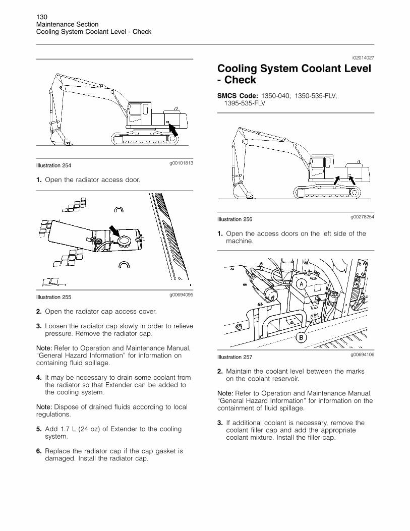
1. Open the radiator access door.
g00694095Illustration 255
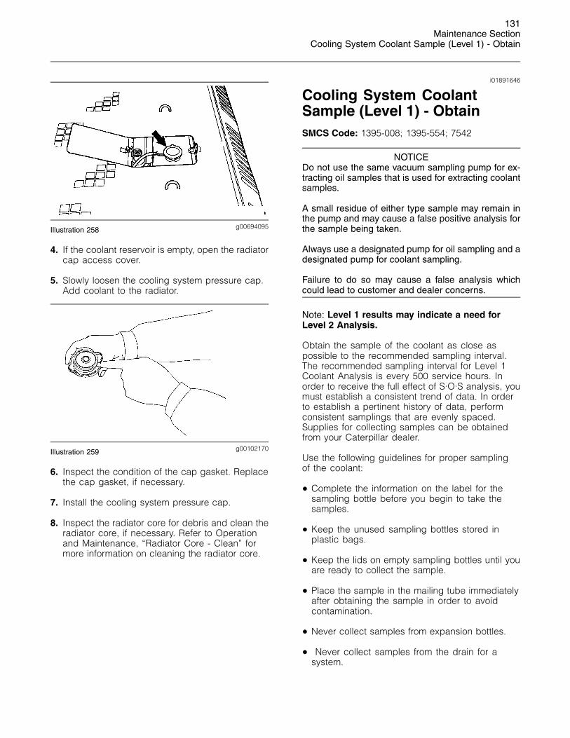
2. Open the radiator cap access cover.
3. Loosen the radiator cap slowly in order to relievepressure. Remove the radiator cap.
Note: Refer to Operation and Maintenance Manual,“General Hazard Information” for information oncontaining fluid spillage.
4. It may be necessary to drain some coolant fromthe radiator so that Extender can be added tothe cooling system.
Note: Dispose of drained fluids according to localregulations.
5. Add 1.7 L (24 oz) of Extender to the coolingsystem.
6. Replace the radiator cap if the cap gasket isdamaged. Install the radiator cap.
i02014027
Cooling System Coolant Level- CheckSMCS Code: 1350-040; 1350-535-FLV;
1395-535-FLV
g00278254Illustration 256
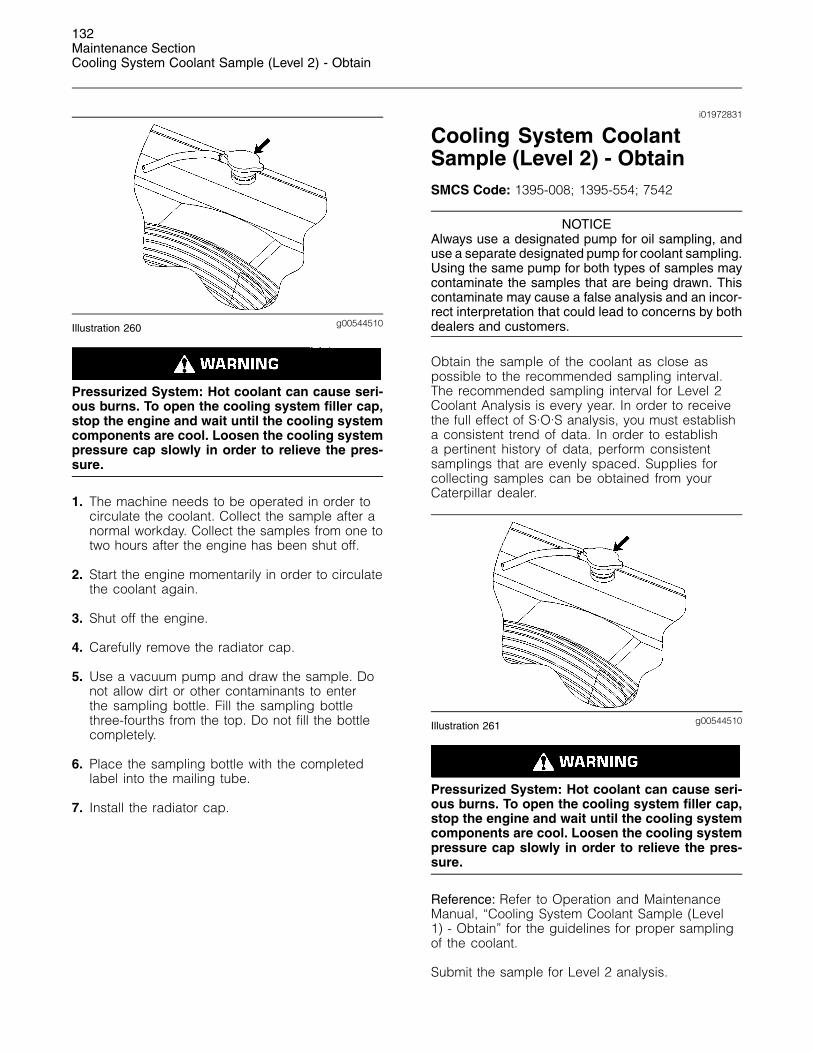
1. Open the access doors on the left side of themachine.
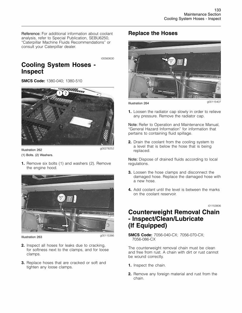
g00694106Illustration 257
2. Maintain the coolant level between the markson the coolant reservoir.
Note: Refer to Operation and Maintenance Manual,“General Hazard Information” for information on thecontainment of fluid spillage.
3. If additional coolant is necessary, remove thecoolant filler cap and add the appropriatecoolant mixture. Install the filler cap.
131Maintenance Section
Cooling System Coolant Sample (Level 1) - Obtain
g00694095Illustration 258
4. If the coolant reservoir is empty, open the radiatorcap access cover.
5. Slowly loosen the cooling system pressure cap.Add coolant to the radiator.
g00102170Illustration 259
6. Inspect the condition of the cap gasket. Replacethe cap gasket, if necessary.
7. Install the cooling system pressure cap.
8. Inspect the radiator core for debris and clean theradiator core, if necessary. Refer to Operationand Maintenance, “Radiator Core - Clean” formore information on cleaning the radiator core.
i01891646
Cooling System CoolantSample (Level 1) - ObtainSMCS Code: 1395-008; 1395-554; 7542
NOTICEDo not use the same vacuum sampling pump for ex-tracting oil samples that is used for extracting coolantsamples.
A small residue of either type sample may remain inthe pump and may cause a false positive analysis forthe sample being taken.
Always use a designated pump for oil sampling and adesignated pump for coolant sampling.
Failure to do so may cause a false analysis whichcould lead to customer and dealer concerns.
Note: Level 1 results may indicate a need forLevel 2 Analysis.
Obtain the sample of the coolant as close aspossible to the recommended sampling interval.The recommended sampling interval for Level 1Coolant Analysis is every 500 service hours. Inorder to receive the full effect of S·O·S analysis, youmust establish a consistent trend of data. In orderto establish a pertinent history of data, performconsistent samplings that are evenly spaced.Supplies for collecting samples can be obtainedfrom your Caterpillar dealer.
Use the following guidelines for proper samplingof the coolant:
• Complete the information on the label for thesampling bottle before you begin to take thesamples.
• Keep the unused sampling bottles stored inplastic bags.
• Keep the lids on empty sampling bottles until youare ready to collect the sample.
• Place the sample in the mailing tube immediatelyafter obtaining the sample in order to avoidcontamination.
• Never collect samples from expansion bottles.
• Never collect samples from the drain for asystem.
132Maintenance SectionCooling System Coolant Sample (Level 2) - Obtain
g00544510Illustration 260
Pressurized System: Hot coolant can cause seri-ous burns. To open the cooling system filler cap,stop the engine and wait until the cooling systemcomponents are cool. Loosen the cooling systempressure cap slowly in order to relieve the pres-sure.
1. The machine needs to be operated in order tocirculate the coolant. Collect the sample after anormal workday. Collect the samples from one totwo hours after the engine has been shut off.
2. Start the engine momentarily in order to circulatethe coolant again.
3. Shut off the engine.
4. Carefully remove the radiator cap.
5. Use a vacuum pump and draw the sample. Donot allow dirt or other contaminants to enterthe sampling bottle. Fill the sampling bottlethree-fourths from the top. Do not fill the bottlecompletely.
6. Place the sampling bottle with the completedlabel into the mailing tube.
7. Install the radiator cap.
i01972831
Cooling System CoolantSample (Level 2) - ObtainSMCS Code: 1395-008; 1395-554; 7542
NOTICEAlways use a designated pump for oil sampling, anduse a separate designated pump for coolant sampling.Using the same pump for both types of samples maycontaminate the samples that are being drawn. Thiscontaminate may cause a false analysis and an incor-rect interpretation that could lead to concerns by bothdealers and customers.
Obtain the sample of the coolant as close aspossible to the recommended sampling interval.The recommended sampling interval for Level 2Coolant Analysis is every year. In order to receivethe full effect of S·O·S analysis, you must establisha consistent trend of data. In order to establisha pertinent history of data, perform consistentsamplings that are evenly spaced. Supplies forcollecting samples can be obtained from yourCaterpillar dealer.
g00544510Illustration 261
Pressurized System: Hot coolant can cause seri-ous burns. To open the cooling system filler cap,stop the engine and wait until the cooling systemcomponents are cool. Loosen the cooling systempressure cap slowly in order to relieve the pres-sure.
Reference: Refer to Operation and MaintenanceManual, “Cooling System Coolant Sample (Level1) - Obtain” for the guidelines for proper samplingof the coolant.
Submit the sample for Level 2 analysis.
133Maintenance Section
Cooling System Hoses - Inspect
Reference: For additional information about coolantanalysis, refer to Special Publication, SEBU6250,“Caterpillar Machine Fluids Recommendations” orconsult your Caterpillar dealer.
i00560630
Cooling System Hoses -InspectSMCS Code: 1380-040; 1380-510
g00278252Illustration 262
(1) Bolts. (2) Washers.
1. Remove six bolts (1) and washers (2). Removethe engine hood.
g00115386Illustration 263
2. Inspect all hoses for leaks due to cracking,for softness next to the clamps, and for looseclamps.
3. Replace hoses that are cracked or soft andtighten any loose clamps.
Replace the Hoses
g00115407Illustration 264
1. Loosen the radiator cap slowly in order to relieveany pressure. Remove the radiator cap.
Note: Refer to Operation and Maintenance Manual,“General Hazard Information” for information thatpertains to containing fluid spillage.
2. Drain the coolant from the cooling system toa level that is below the hose that is beingreplaced.
Note: Dispose of drained fluids according to localregulations.
3. Loosen the hose clamps and disconnect thedamaged hose. Replace the damaged hose witha new hose.
4. Add coolant until the level is between the markson the coolant reservoir.
i01153806
Counterweight Removal Chain- Inspect/Clean/Lubricate(If Equipped)SMCS Code: 7056-040-CX; 7056-070-CX;
7056-086-CX
The counterweight removal chain must be cleanand free from rust. A chain with dirt or rust cannotbe wound correctly.
1. Inspect the chain.
2. Remove any foreign material and rust from thechain.
134Maintenance SectionEngine Air Filter Primary Element - Clean/Replace
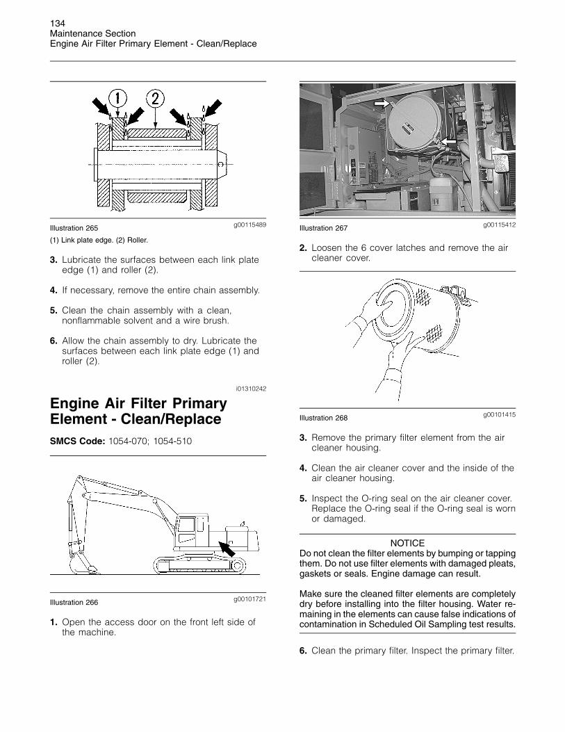
g00115489Illustration 265
(1) Link plate edge. (2) Roller.
3. Lubricate the surfaces between each link plateedge (1) and roller (2).
4. If necessary, remove the entire chain assembly.
5. Clean the chain assembly with a clean,nonflammable solvent and a wire brush.
6. Allow the chain assembly to dry. Lubricate thesurfaces between each link plate edge (1) androller (2).
i01310242
Engine Air Filter PrimaryElement - Clean/ReplaceSMCS Code: 1054-070; 1054-510
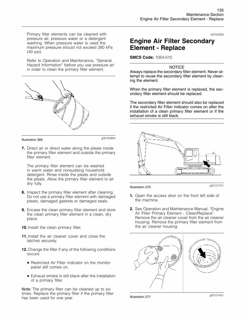
g00101721Illustration 266
1. Open the access door on the front left side ofthe machine.
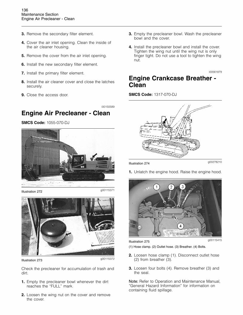
g00115412Illustration 267
2. Loosen the 6 cover latches and remove the aircleaner cover.
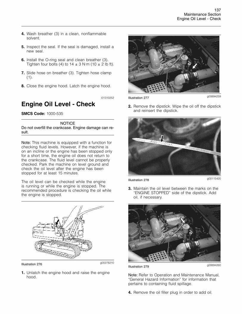
g00101415Illustration 268
3. Remove the primary filter element from the aircleaner housing.
4. Clean the air cleaner cover and the inside of theair cleaner housing.
5. Inspect the O-ring seal on the air cleaner cover.Replace the O-ring seal if the O-ring seal is wornor damaged.
NOTICEDo not clean the filter elements by bumping or tappingthem. Do not use filter elements with damaged pleats,gaskets or seals. Engine damage can result.
Make sure the cleaned filter elements are completelydry before installing into the filter housing. Water re-maining in the elements can cause false indications ofcontamination in Scheduled Oil Sampling test results.
6. Clean the primary filter. Inspect the primary filter.
135Maintenance Section
Engine Air Filter Secondary Element - Replace
Primary filter elements can be cleaned withpressure air, pressure water or a detergentwashing. When pressure water is used themaximum pressure should not exceed 280 kPa(40 psi).
Refer to Operation and Maintenance, “GeneralHazard Information” before you use pressure airin order to clean the primary filter element.
g00102884Illustration 269
7. Direct air or direct water along the pleats insidethe primary filter element and outside the primaryfilter element.
The primary filter element can be washedin warm water and nonsudsing householddetergent. Rinse inside the pleats and outsidethe pleats. Allow the primary filter element to airdry fully.
8. Inspect the primary filter element after cleaning.Do not use a primary filter element with damagedpleats, damaged gaskets or damaged seals.
9. Encase the clean primary filter element and storethe clean primary filter element in a clean, dryplace.
10. Install the clean primary filter.
11. Install the air cleaner cover and close thelatches securely.
12. Change the filter if any of the following conditionsoccurs:
• Restricted Air Filter indicator on the monitorpanel still comes on.
• Exhaust smoke is still black after the installationof a primary filter.
Note: The primary filter can be cleaned up to sixtimes. Replace the primary filter if the primary filterhas been used for one year.
i00702568
Engine Air Filter SecondaryElement - ReplaceSMCS Code: 1054-510
NOTICEAlways replace the secondary filter element. Never at-tempt to reuse the secondary filter element by clean-ing the element.
When the primary filter element is replaced, the sec-ondary filter element should be replaced.
The secondary filter element should also be replacedif the restricted Air Filter indicator comes on after theinstallation of a clean primary filter element or if theexhaust smoke is still black.
g00101721Illustration 270
1. Open the access door on the front left side ofthe machine.
2. See Operation and Maintenance Manual, “EngineAir Filter Primary Element - Clean/Replace”.Remove the air cleaner cover from the air cleanerhousing. Remove the primary filter element fromthe air cleaner housing.
g00101451Illustration 271
136Maintenance SectionEngine Air Precleaner - Clean
3. Remove the secondary filter element.
4. Cover the air inlet opening. Clean the inside ofthe air cleaner housing.
5. Remove the cover from the air inlet opening.
6. Install the new secondary filter element.
7. Install the primary filter element.
8. Install the air cleaner cover and close the latchessecurely.
9. Close the access door.
i00150589
Engine Air Precleaner - CleanSMCS Code: 1055-070-DJ
g00115371Illustration 272
g00115372Illustration 273
Check the precleaner for accumulation of trash anddirt.
1. Empty the precleaner bowl whenever the dirtreaches the “FULL” mark.
2. Loosen the wing nut on the cover and removethe cover.
3. Empty the precleaner bowl. Wash the precleanerbowl and the cover.
4. Install the precleaner bowl and install the cover.Tighten the wing nut until the wing nut is onlyfinger tight. Do not use a tool to tighten the wingnut.
i00561879
Engine Crankcase Breather -CleanSMCS Code: 1317-070-DJ
g00278210Illustration 274
1. Unlatch the engine hood. Raise the engine hood.
g00115415Illustration 275
(1) Hose clamp. (2) Outlet hose. (3) Breather. (4) Bolts.
2. Loosen hose clamp (1). Disconnect outlet hose(2) from breather (3).
3. Loosen four bolts (4). Remove breather (3) andthe seal.
Note: Refer to Operation and Maintenance Manual,“General Hazard Information” for information oncontaining fluid spillage.
137Maintenance Section
Engine Oil Level - Check
4. Wash breather (3) in a clean, nonflammablesolvent.
5. Inspect the seal. If the seal is damaged, install anew seal.
6. Install the O-ring seal and clean breather (3).Tighten four bolts (4) to 14 ± 3 N·m (10 ± 2 lb ft).
7. Slide hose on breather (3). Tighten hose clamp(1).
8. Close the engine hood. Latch the engine hood.
i01310252
Engine Oil Level - CheckSMCS Code: 1000-535
NOTICEDo not overfill the crankcase. Engine damage can re-sult.
Note: This machine is equipped with a function forchecking fluid levels. However, if the machine ison an incline or the engine has been stopped onlyfor a short time, the engine oil does not return tothe crankcase. The fluid level cannot be properlychecked. Park the machine on level ground andcheck the oil level after the engine has beenstopped for at least 15 minutes.
The oil level can be checked while the engineis running or while the engine is stopped. Therecommended procedure is checking the oil whilethe engine is stopped.
g00278210Illustration 276
1. Unlatch the engine hood and raise the enginehood.
g00694259Illustration 277
2. Remove the dipstick. Wipe the oil off the dipstickand reinsert the dipstick.
g00115420Illustration 278
3. Maintain the oil level between the marks on the“ENGINE STOPPED” side of the dipstick. Addoil, if necessary.
g00694260Illustration 279
Note: Refer to Operation and Maintenance Manual,“General Hazard Information” for information thatpertains to containing fluid spillage.
4. Remove the oil filler plug in order to add oil.
138Maintenance SectionEngine Oil Sample - Obtain
Note: Oil that is badly contaminated or deterioratedshould be replaced early regardless of the changeinterval.
5. Clean the filler plug and install the filler plug.
6. Close the engine hood and latch the enginehood.
i01958488
Engine Oil Sample - ObtainSMCS Code: 1000-008; 1000; 1348-008;
1348-554-SM; 7542-008; 7542-554-OC, SM
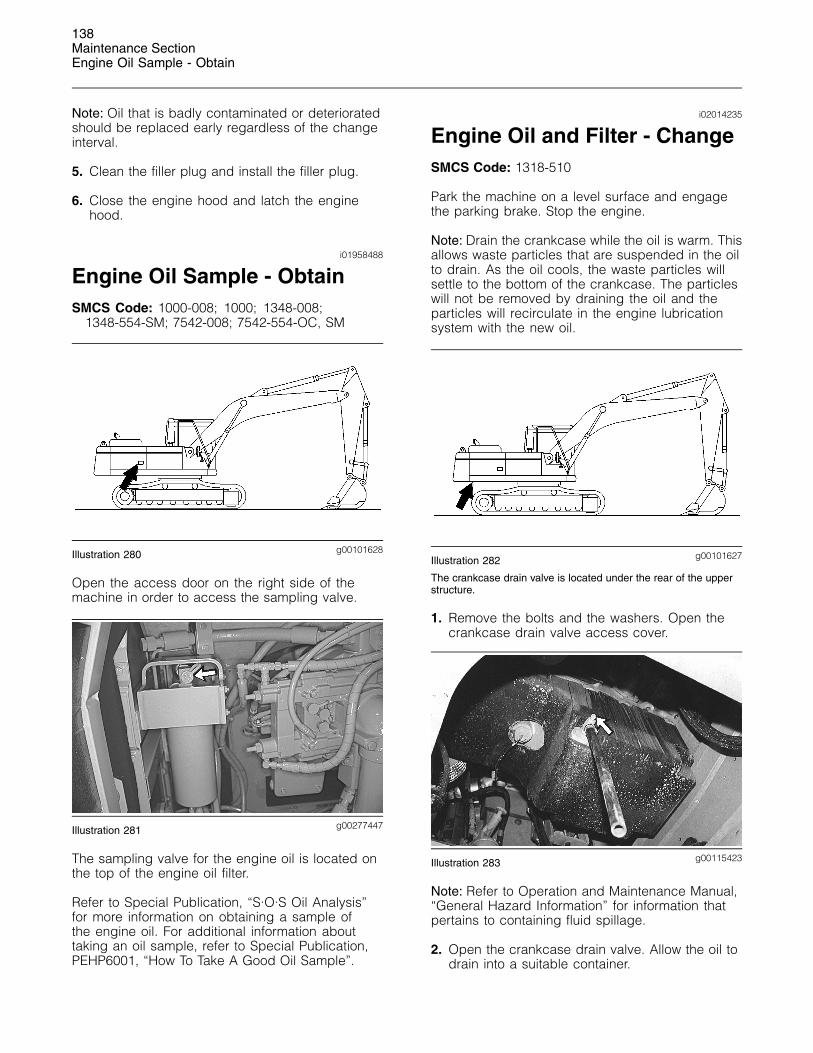
g00101628Illustration 280
Open the access door on the right side of themachine in order to access the sampling valve.
g00277447Illustration 281
The sampling valve for the engine oil is located onthe top of the engine oil filter.
Refer to Special Publication, “S·O·S Oil Analysis”for more information on obtaining a sample ofthe engine oil. For additional information abouttaking an oil sample, refer to Special Publication,PEHP6001, “How To Take A Good Oil Sample”.
i02014235
Engine Oil and Filter - ChangeSMCS Code: 1318-510
Park the machine on a level surface and engagethe parking brake. Stop the engine.
Note: Drain the crankcase while the oil is warm. Thisallows waste particles that are suspended in the oilto drain. As the oil cools, the waste particles willsettle to the bottom of the crankcase. The particleswill not be removed by draining the oil and theparticles will recirculate in the engine lubricationsystem with the new oil.
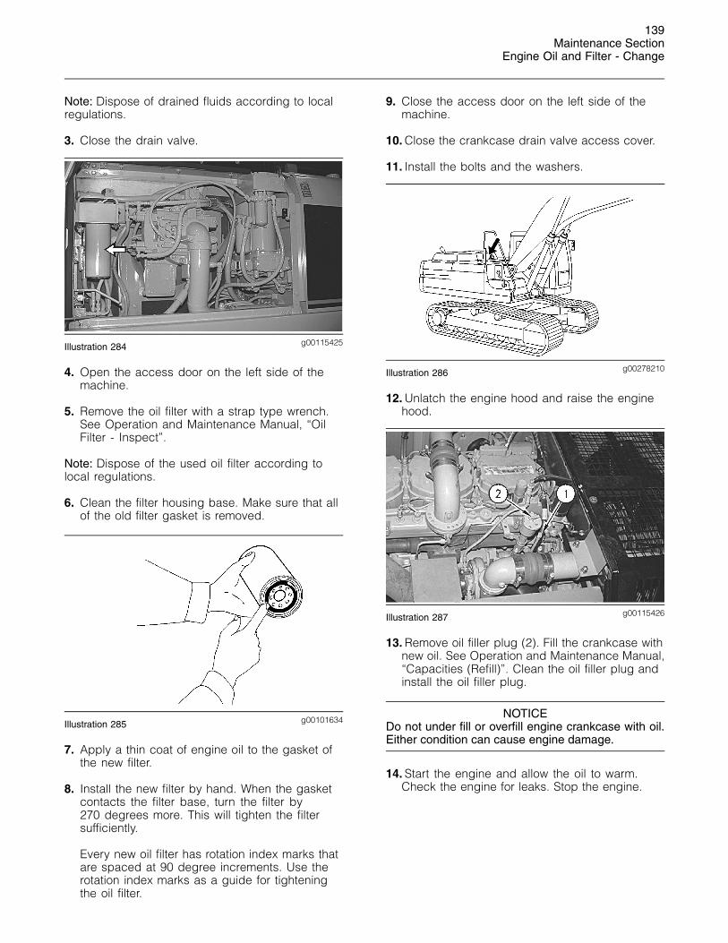
g00101627Illustration 282
The crankcase drain valve is located under the rear of the upperstructure.
1. Remove the bolts and the washers. Open thecrankcase drain valve access cover.
g00115423Illustration 283
Note: Refer to Operation and Maintenance Manual,“General Hazard Information” for information thatpertains to containing fluid spillage.
2. Open the crankcase drain valve. Allow the oil todrain into a suitable container.
139Maintenance Section
Engine Oil and Filter - Change
Note: Dispose of drained fluids according to localregulations.
3. Close the drain valve.
g00115425Illustration 284
4. Open the access door on the left side of themachine.
5. Remove the oil filter with a strap type wrench.See Operation and Maintenance Manual, “OilFilter - Inspect”.
Note: Dispose of the used oil filter according tolocal regulations.
6. Clean the filter housing base. Make sure that allof the old filter gasket is removed.
g00101634Illustration 285
7. Apply a thin coat of engine oil to the gasket ofthe new filter.
8. Install the new filter by hand. When the gasketcontacts the filter base, turn the filter by270 degrees more. This will tighten the filtersufficiently.
Every new oil filter has rotation index marks thatare spaced at 90 degree increments. Use therotation index marks as a guide for tighteningthe oil filter.
9. Close the access door on the left side of themachine.
10. Close the crankcase drain valve access cover.
11. Install the bolts and the washers.
g00278210Illustration 286
12. Unlatch the engine hood and raise the enginehood.
g00115426Illustration 287
13. Remove oil filler plug (2). Fill the crankcase withnew oil. See Operation and Maintenance Manual,“Capacities (Refill)”. Clean the oil filler plug andinstall the oil filler plug.
NOTICEDo not under fill or overfill engine crankcase with oil.Either condition can cause engine damage.
14. Start the engine and allow the oil to warm.Check the engine for leaks. Stop the engine.
140Maintenance SectionEngine Valve Lash and Fuel Injector Timing - Check
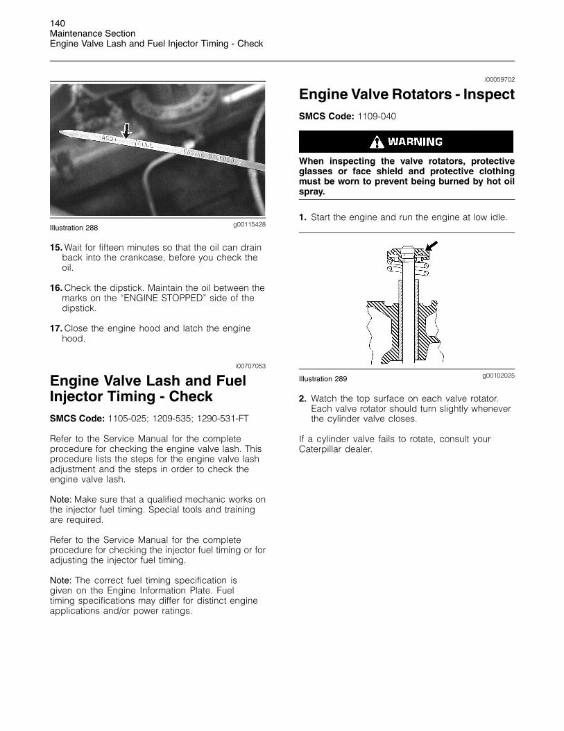
g00115428Illustration 288
15. Wait for fifteen minutes so that the oil can drainback into the crankcase, before you check theoil.
16. Check the dipstick. Maintain the oil between themarks on the “ENGINE STOPPED” side of thedipstick.
17. Close the engine hood and latch the enginehood.
i00707053
Engine Valve Lash and FuelInjector Timing - CheckSMCS Code: 1105-025; 1209-535; 1290-531-FT
Refer to the Service Manual for the completeprocedure for checking the engine valve lash. Thisprocedure lists the steps for the engine valve lashadjustment and the steps in order to check theengine valve lash.
Note: Make sure that a qualified mechanic works onthe injector fuel timing. Special tools and trainingare required.
Refer to the Service Manual for the completeprocedure for checking the injector fuel timing or foradjusting the injector fuel timing.
Note: The correct fuel timing specification isgiven on the Engine Information Plate. Fueltiming specifications may differ for distinct engineapplications and/or power ratings.
i00059702
Engine Valve Rotators - InspectSMCS Code: 1109-040
When inspecting the valve rotators, protectiveglasses or face shield and protective clothingmust be worn to prevent being burned by hot oilspray.
1. Start the engine and run the engine at low idle.
g00102025Illustration 289
2. Watch the top surface on each valve rotator.Each valve rotator should turn slightly wheneverthe cylinder valve closes.
If a cylinder valve fails to rotate, consult yourCaterpillar dealer.
141Maintenance Section
Ether Starting Aid Cylinder - Replace
i01313174
Ether Starting Aid Cylinder -ReplaceSMCS Code: 1456-510-CD
g00101721Illustration 290
The ether cylinder is located inside the front access door on thefront left side of the machine.
Refer to Operation and Maintenance, “FirePrevention and Explosion Prevention” before youreplace the ether cylinders.
1. Open the front access door on the left side ofthe machine.
g00695152Illustration 291
2. Loosen the cylinder retaining clamp. Unscrewthe empty ether cylinder and remove the emptyether cylinder.
g00695155Illustration 292
3. Remove the used gasket. Install the new gasket.A new gasket is provided with each new etherstarting aid cylinder.
4. Install the new ether starting aid cylinder. Tightenthe ether starting aid cylinder hand tight. Tightenthe cylinder retaining clamp securely.
5. Close the access door.
i01584908
Final Drive Oil - ChangeSMCS Code: 4050-044-FLV
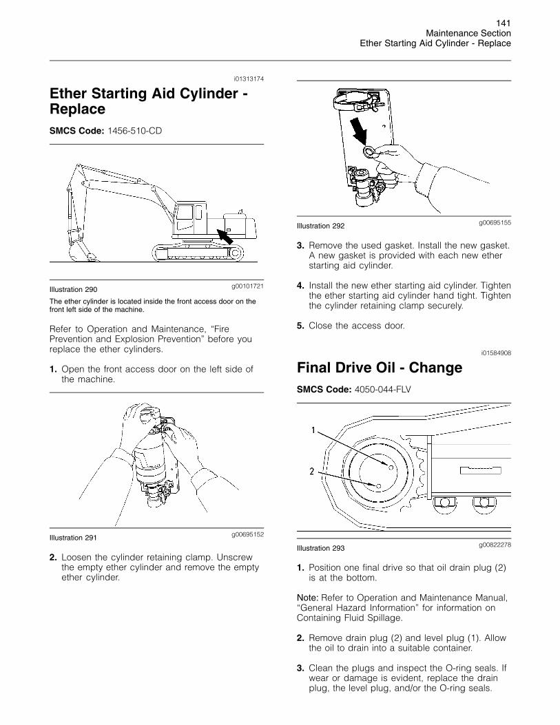
g00822278Illustration 293
1. Position one final drive so that oil drain plug (2)is at the bottom.
Note: Refer to Operation and Maintenance Manual,“General Hazard Information” for information onContaining Fluid Spillage.
2. Remove drain plug (2) and level plug (1). Allowthe oil to drain into a suitable container.
3. Clean the plugs and inspect the O-ring seals. Ifwear or damage is evident, replace the drainplug, the level plug, and/or the O-ring seals.
142Maintenance SectionFinal Drive Oil Level - Check
4. Install drain plug (2).
5. Fill the final drive to the bottom of the opening onlevel plug (1). See Operation and MaintenanceManual, “Lubricant Viscosities” and Operationand Maintenance Manual, “Capacities (Refill) ”.
6. Install level plug (1).
7. Perform Step 1 to Step 6 on the other final drive.Use a different container for the oil so that the oilsamples from the final drives will be separate.
8. Completely remove the oil that has spilled ontosurfaces.
9. Start the engine and allow the final drives to runthrough several cycles.
10. Stop the engine. Check the oil level.
11. Check the drained oil for metal chips or forparticles. If there are any chips or particles,consult your Caterpillar dealer.
12. Properly dispose of the drained material. Obeylocal regulations for the disposal of the material.
i01589592
Final Drive Oil Level - CheckSMCS Code: 4050-535-FLV
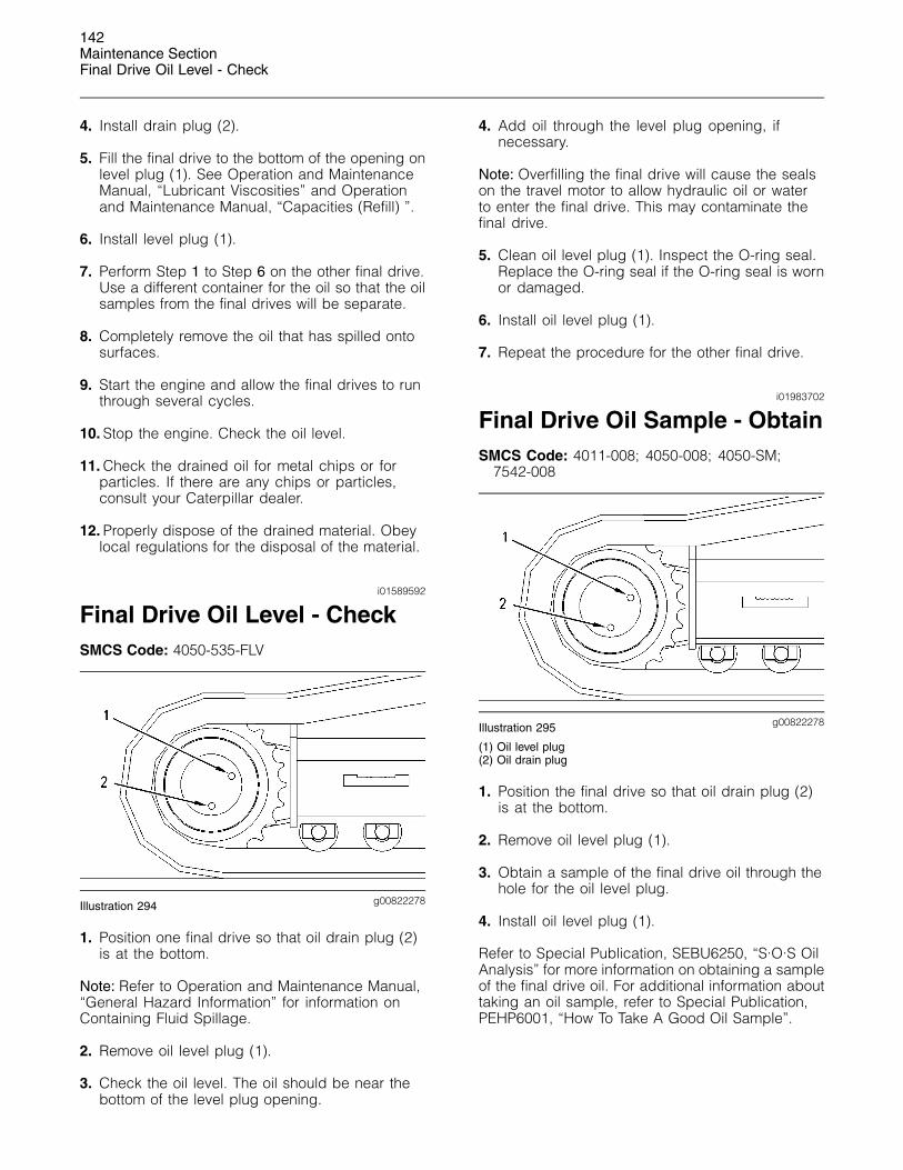
g00822278Illustration 294
1. Position one final drive so that oil drain plug (2)is at the bottom.
Note: Refer to Operation and Maintenance Manual,“General Hazard Information” for information onContaining Fluid Spillage.
2. Remove oil level plug (1).
3. Check the oil level. The oil should be near thebottom of the level plug opening.
4. Add oil through the level plug opening, ifnecessary.
Note: Overfilling the final drive will cause the sealson the travel motor to allow hydraulic oil or waterto enter the final drive. This may contaminate thefinal drive.
5. Clean oil level plug (1). Inspect the O-ring seal.Replace the O-ring seal if the O-ring seal is wornor damaged.
6. Install oil level plug (1).
7. Repeat the procedure for the other final drive.
i01983702
Final Drive Oil Sample - ObtainSMCS Code: 4011-008; 4050-008; 4050-SM;
7542-008
g00822278Illustration 295
(1) Oil level plug(2) Oil drain plug
1. Position the final drive so that oil drain plug (2)is at the bottom.
2. Remove oil level plug (1).
3. Obtain a sample of the final drive oil through thehole for the oil level plug.
4. Install oil level plug (1).
Refer to Special Publication, SEBU6250, “S·O·S OilAnalysis” for more information on obtaining a sampleof the final drive oil. For additional information abouttaking an oil sample, refer to Special Publication,PEHP6001, “How To Take A Good Oil Sample”.
143Maintenance SectionFuel System - Prime
i02024665
Fuel System - PrimeSMCS Code: 1250-548
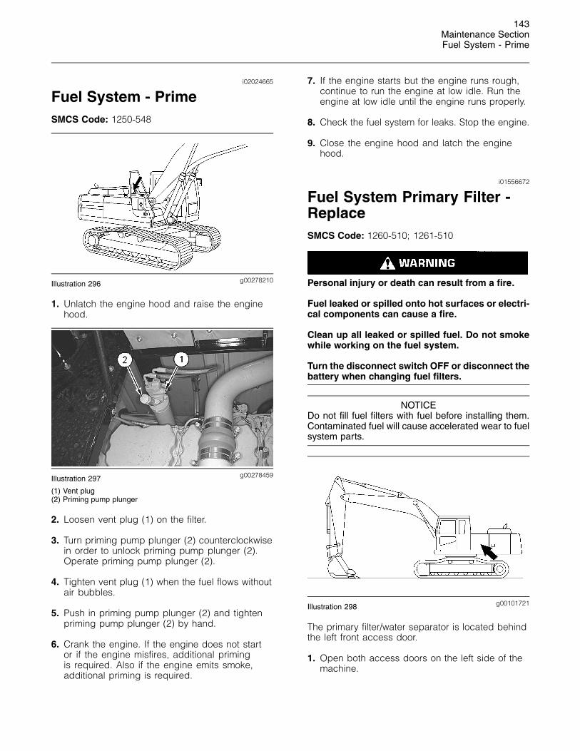
g00278210Illustration 296
1. Unlatch the engine hood and raise the enginehood.
g00278459Illustration 297
(1) Vent plug(2) Priming pump plunger
2. Loosen vent plug (1) on the filter.
3. Turn priming pump plunger (2) counterclockwisein order to unlock priming pump plunger (2).Operate priming pump plunger (2).
4. Tighten vent plug (1) when the fuel flows withoutair bubbles.
5. Push in priming pump plunger (2) and tightenpriming pump plunger (2) by hand.
6. Crank the engine. If the engine does not startor if the engine misfires, additional primingis required. Also if the engine emits smoke,additional priming is required.
7. If the engine starts but the engine runs rough,continue to run the engine at low idle. Run theengine at low idle until the engine runs properly.
8. Check the fuel system for leaks. Stop the engine.
9. Close the engine hood and latch the enginehood.
i01556672
Fuel System Primary Filter -ReplaceSMCS Code: 1260-510; 1261-510
Personal injury or death can result from a fire.
Fuel leaked or spilled onto hot surfaces or electri-cal components can cause a fire.
Clean up all leaked or spilled fuel. Do not smokewhile working on the fuel system.
Turn the disconnect switch OFF or disconnect thebattery when changing fuel filters.
NOTICEDo not fill fuel filters with fuel before installing them.Contaminated fuel will cause accelerated wear to fuelsystem parts.
g00101721Illustration 298
The primary filter/water separator is located behindthe left front access door.
1. Open both access doors on the left side of themachine.
144Maintenance SectionFuel System Secondary Filter - Replace
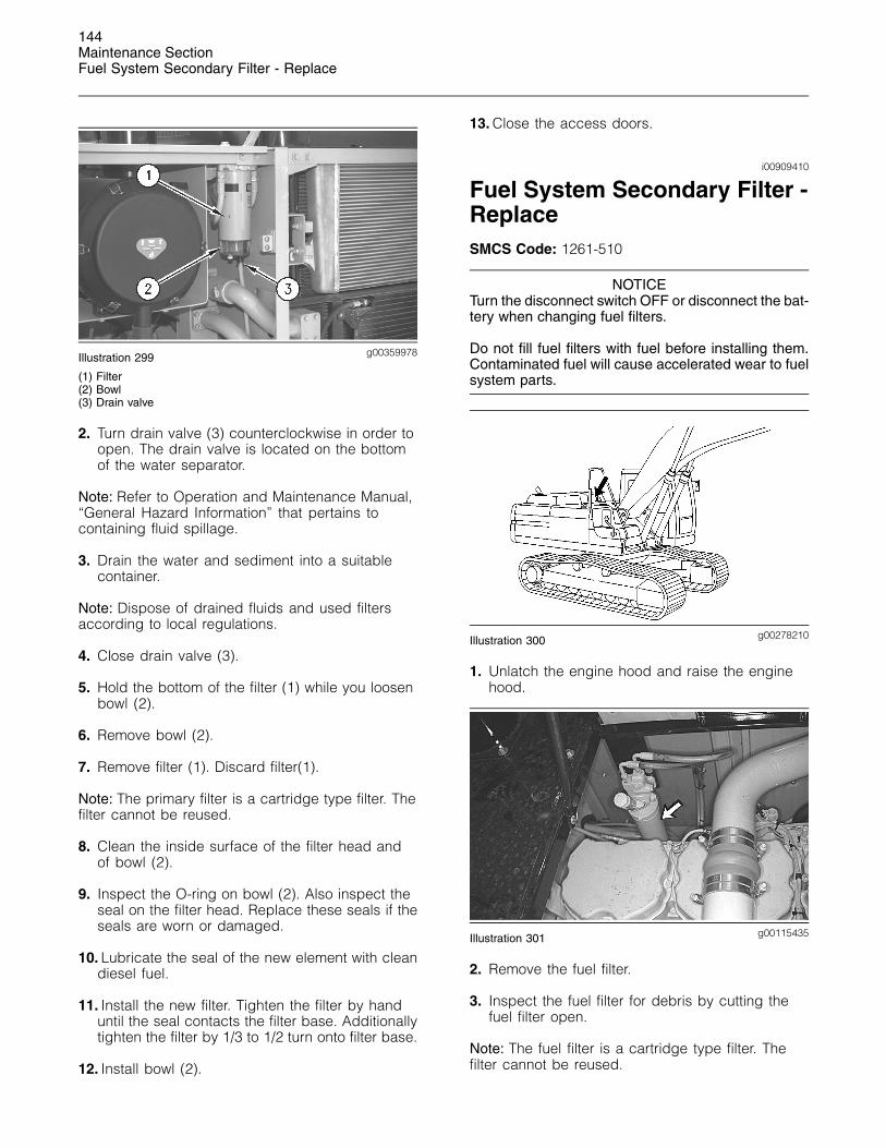
g00359978Illustration 299
(1) Filter(2) Bowl(3) Drain valve
2. Turn drain valve (3) counterclockwise in order toopen. The drain valve is located on the bottomof the water separator.
Note: Refer to Operation and Maintenance Manual,“General Hazard Information” that pertains tocontaining fluid spillage.
3. Drain the water and sediment into a suitablecontainer.
Note: Dispose of drained fluids and used filtersaccording to local regulations.
4. Close drain valve (3).
5. Hold the bottom of the filter (1) while you loosenbowl (2).
6. Remove bowl (2).
7. Remove filter (1). Discard filter(1).
Note: The primary filter is a cartridge type filter. Thefilter cannot be reused.
8. Clean the inside surface of the filter head andof bowl (2).
9. Inspect the O-ring on bowl (2). Also inspect theseal on the filter head. Replace these seals if theseals are worn or damaged.
10. Lubricate the seal of the new element with cleandiesel fuel.
11. Install the new filter. Tighten the filter by handuntil the seal contacts the filter base. Additionallytighten the filter by 1/3 to 1/2 turn onto filter base.
12. Install bowl (2).
13. Close the access doors.
i00909410
Fuel System Secondary Filter -ReplaceSMCS Code: 1261-510
NOTICETurn the disconnect switch OFF or disconnect the bat-tery when changing fuel filters.
Do not fill fuel filters with fuel before installing them.Contaminated fuel will cause accelerated wear to fuelsystem parts.
g00278210Illustration 300
1. Unlatch the engine hood and raise the enginehood.
g00115435Illustration 301
2. Remove the fuel filter.
3. Inspect the fuel filter for debris by cutting thefuel filter open.
Note: The fuel filter is a cartridge type filter. Thefilter cannot be reused.
145Maintenance Section
Fuel System Water Separator - Drain
Note: Dispose of used filters and used fluidsaccording to local regulations.
4. Clean the filter mounting base. Make sure that allof the old seal is removed.
g00101634Illustration 302
5. Lubricate the seal of the new filter with cleandiesel fuel.
6. Install the new filter by hand. Additionally tightenthe filter by 3/4 of a turn, after the gasketcontacts the filter base.
The filter has rotation index marks that arespaced at 90 degree intervals. Use these rotationindex marks as a guide for proper tightening.
7. Prime the fuel system. Refer to Operation andMaintenance, “Fuel System Priming Pump -Operate”.
i00779879
Fuel System Water Separator- DrainSMCS Code: 1263
g00101721Illustration 303
The water separator is located inside the front access door on thefront left side of the machine.
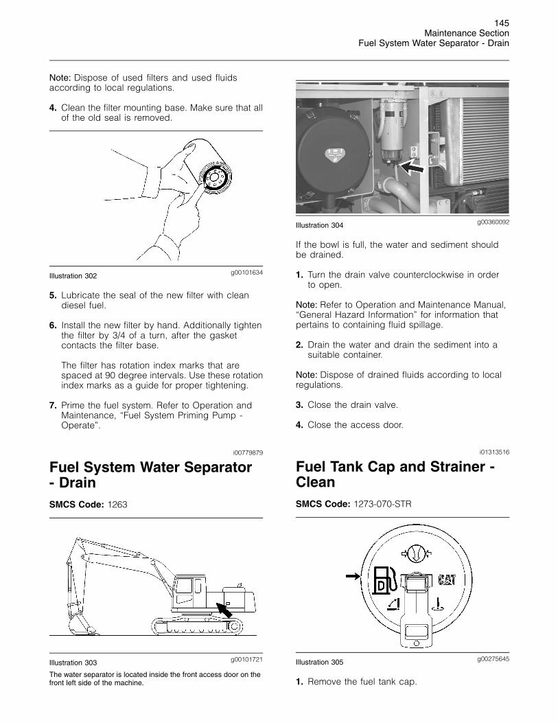
g00360092Illustration 304
If the bowl is full, the water and sediment shouldbe drained.
1. Turn the drain valve counterclockwise in orderto open.
Note: Refer to Operation and Maintenance Manual,“General Hazard Information” for information thatpertains to containing fluid spillage.
2. Drain the water and drain the sediment into asuitable container.
Note: Dispose of drained fluids according to localregulations.
3. Close the drain valve.
4. Close the access door.
i01313516
Fuel Tank Cap and Strainer -CleanSMCS Code: 1273-070-STR
g00275645Illustration 305
1. Remove the fuel tank cap.
146Maintenance SectionFuel Tank Water and Sediment - Drain
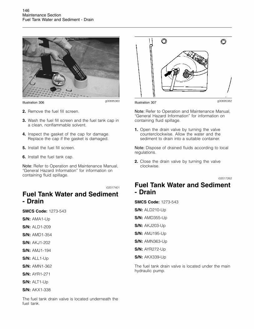
g00695360Illustration 306
2. Remove the fuel fill screen.
3. Wash the fuel fill screen and the fuel tank cap ina clean, nonflammable solvent.
4. Inspect the gasket of the cap for damage.Replace the cap if the gasket is damaged.
5. Install the fuel fill screen.
6. Install the fuel tank cap.
Note: Refer to Operation and Maintenance Manual,“General Hazard Information” for information oncontaining fluid spillage.
i02017401
Fuel Tank Water and Sediment- DrainSMCS Code: 1273-543
S/N: AMA1-Up
S/N: ALD1-209
S/N: AMD1-354
S/N: AKJ1-202
S/N: AMJ1-194
S/N: ALL1-Up
S/N: AMN1-362
S/N: AYR1-271
S/N: ALT1-Up
S/N: AKX1-338
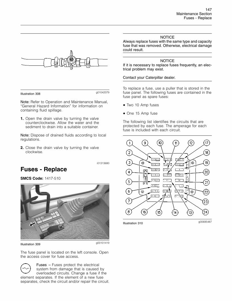
The fuel tank drain valve is located underneath thefuel tank.
g00695382Illustration 307
Note: Refer to Operation and Maintenance Manual,“General Hazard Information” for information oncontaining fluid spillage.
1. Open the drain valve by turning the valvecounterclockwise. Allow the water and thesediment to drain into a suitable container.
Note: Dispose of drained fluids according to localregulations.
2. Close the drain valve by turning the valveclockwise.
i02017262
Fuel Tank Water and Sediment- DrainSMCS Code: 1273-543
S/N: ALD210-Up
S/N: AMD355-Up
S/N: AKJ203-Up
S/N: AMJ195-Up
S/N: AMN363-Up
S/N: AYR272-Up
S/N: AKX339-Up
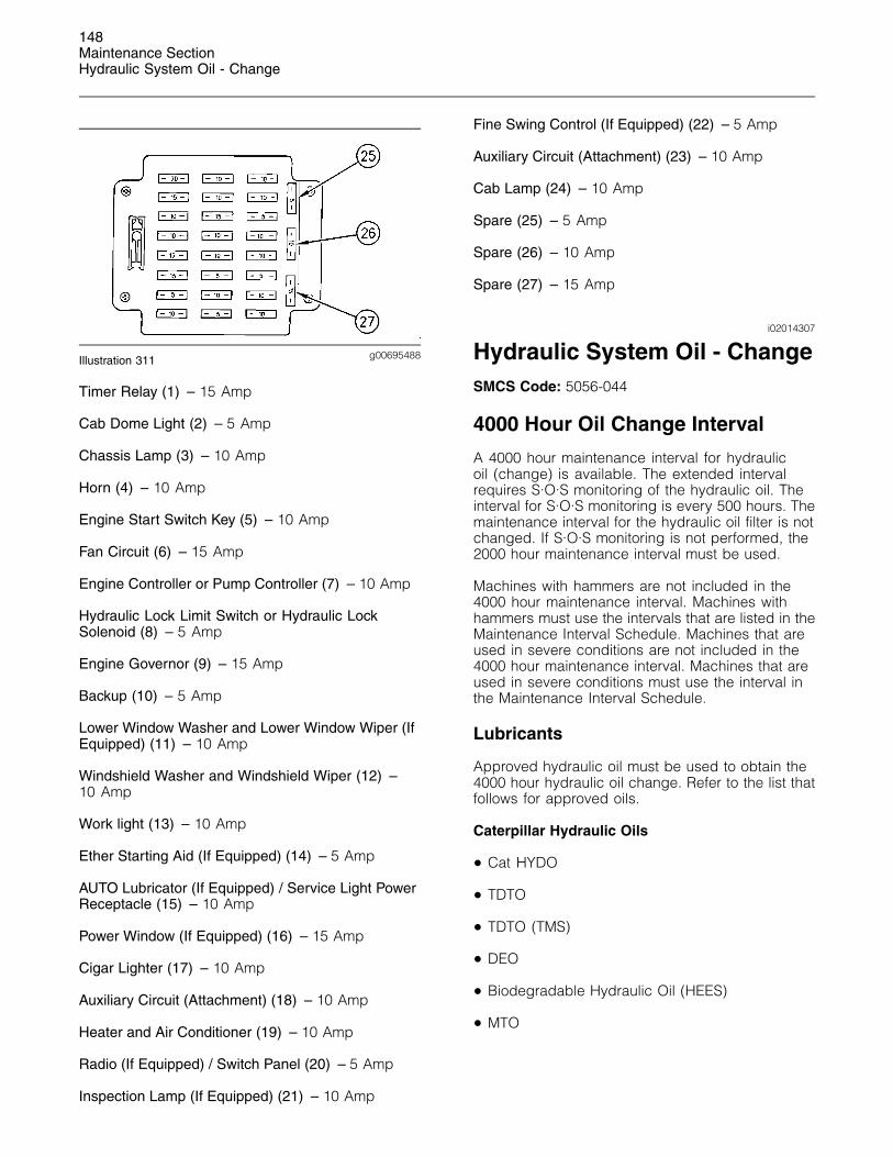
The fuel tank drain valve is located under the mainhydraulic pump.
147Maintenance Section
Fuses - Replace
g01042079Illustration 308
Note: Refer to Operation and Maintenance Manual,“General Hazard Information” for information oncontaining fluid spillage.
1. Open the drain valve by turning the valvecounterclockwise. Allow the water and thesediment to drain into a suitable container.
Note: Dispose of drained fluids according to localregulations.
2. Close the drain valve by turning the valveclockwise.
i01313680
Fuses - ReplaceSMCS Code: 1417-510
g00101419Illustration 309
The fuse panel is located on the left console. Openthe access cover for fuse access.
Fuses – Fuses protect the electricalsystem from damage that is caused byoverloaded circuits. Change a fuse if the
element separates. If the element of a new fuseseparates, check the circuit and/or repair the circuit.
NOTICEAlways replace fuses with the same type and capacityfuse that was removed. Otherwise, electrical damagecould result.
NOTICEIf it is necessary to replace fuses frequently, an elec-trical problem may exist.
Contact your Caterpillar dealer.
To replace a fuse, use a puller that is stored in thefuse panel. The following fuses are contained in thefuse panel as spare fuses:
• Two 10 Amp fuses
• One 15 Amp fuse
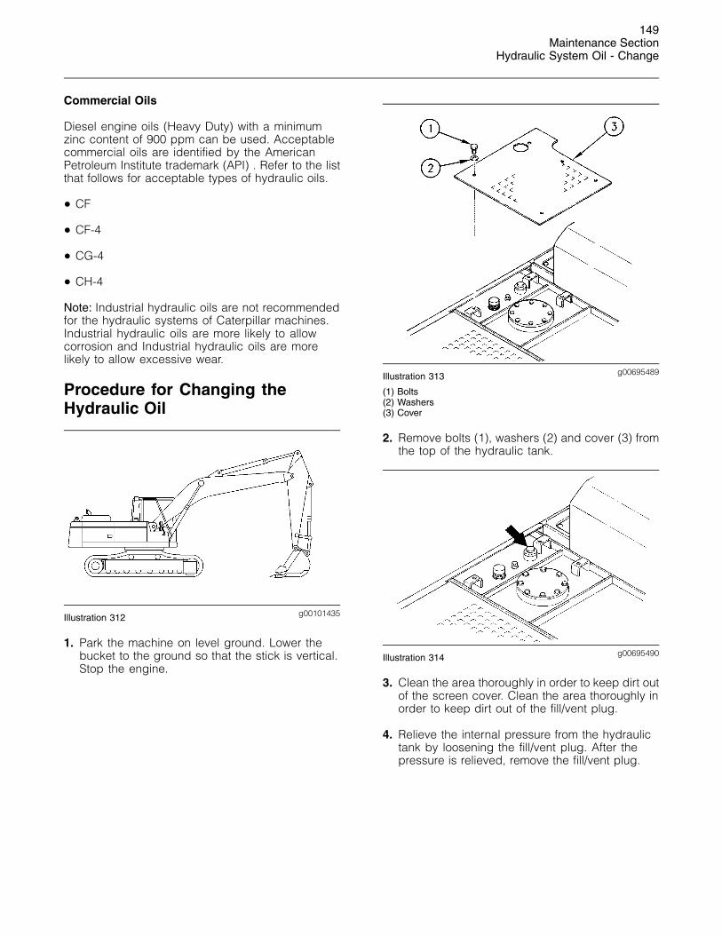
The following list identifies the circuits that areprotected by each fuse. The amperage for eachfuse is included with each circuit.
g00695487Illustration 310
148Maintenance SectionHydraulic System Oil - Change
g00695488Illustration 311
Timer Relay (1) – 15 Amp
Cab Dome Light (2) – 5 Amp
Chassis Lamp (3) – 10 Amp
Horn (4) – 10 Amp
Engine Start Switch Key (5) – 10 Amp
Fan Circuit (6) – 15 Amp
Engine Controller or Pump Controller (7) – 10 Amp
Hydraulic Lock Limit Switch or Hydraulic LockSolenoid (8) – 5 Amp
Engine Governor (9) – 15 Amp
Backup (10) – 5 Amp
Lower Window Washer and Lower Window Wiper (IfEquipped) (11) – 10 Amp
Windshield Washer and Windshield Wiper (12) –10 Amp
Work light (13) – 10 Amp
Ether Starting Aid (If Equipped) (14) – 5 Amp
AUTO Lubricator (If Equipped) / Service Light PowerReceptacle (15) – 10 Amp
Power Window (If Equipped) (16) – 15 Amp
Cigar Lighter (17) – 10 Amp
Auxiliary Circuit (Attachment) (18) – 10 Amp
Heater and Air Conditioner (19) – 10 Amp
Radio (If Equipped) / Switch Panel (20) – 5 Amp
Inspection Lamp (If Equipped) (21) – 10 Amp
Fine Swing Control (If Equipped) (22) – 5 Amp
Auxiliary Circuit (Attachment) (23) – 10 Amp
Cab Lamp (24) – 10 Amp
Spare (25) – 5 Amp
Spare (26) – 10 Amp
Spare (27) – 15 Amp
i02014307
Hydraulic System Oil - ChangeSMCS Code: 5056-044
4000 Hour Oil Change Interval
A 4000 hour maintenance interval for hydraulicoil (change) is available. The extended intervalrequires S·O·S monitoring of the hydraulic oil. Theinterval for S·O·S monitoring is every 500 hours. Themaintenance interval for the hydraulic oil filter is notchanged. If S·O·S monitoring is not performed, the2000 hour maintenance interval must be used.
Machines with hammers are not included in the4000 hour maintenance interval. Machines withhammers must use the intervals that are listed in theMaintenance Interval Schedule. Machines that areused in severe conditions are not included in the4000 hour maintenance interval. Machines that areused in severe conditions must use the interval inthe Maintenance Interval Schedule.
Lubricants
Approved hydraulic oil must be used to obtain the4000 hour hydraulic oil change. Refer to the list thatfollows for approved oils.
Caterpillar Hydraulic Oils
• Cat HYDO
• TDTO
• TDTO (TMS)
• DEO
• Biodegradable Hydraulic Oil (HEES)
• MTO
149Maintenance Section
Hydraulic System Oil - Change
Commercial Oils
Diesel engine oils (Heavy Duty) with a minimumzinc content of 900 ppm can be used. Acceptablecommercial oils are identified by the AmericanPetroleum Institute trademark (API) . Refer to the listthat follows for acceptable types of hydraulic oils.
• CF
• CF-4
• CG-4
• CH-4
Note: Industrial hydraulic oils are not recommendedfor the hydraulic systems of Caterpillar machines.Industrial hydraulic oils are more likely to allowcorrosion and Industrial hydraulic oils are morelikely to allow excessive wear.
Procedure for Changing theHydraulic Oil
g00101435Illustration 312
1. Park the machine on level ground. Lower thebucket to the ground so that the stick is vertical.Stop the engine.
g00695489Illustration 313
(1) Bolts(2) Washers(3) Cover
2. Remove bolts (1), washers (2) and cover (3) fromthe top of the hydraulic tank.
g00695490Illustration 314
3. Clean the area thoroughly in order to keep dirt outof the screen cover. Clean the area thoroughly inorder to keep dirt out of the fill/vent plug.
4. Relieve the internal pressure from the hydraulictank by loosening the fill/vent plug. After thepressure is relieved, remove the fill/vent plug.
150Maintenance SectionHydraulic System Oil - Change
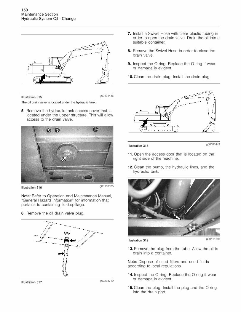
g00101446Illustration 315
The oil drain valve is located under the hydraulic tank.
5. Remove the hydraulic tank access cover that islocated under the upper structure. This will allowaccess to the drain valve.
g00118185Illustration 316
Note: Refer to Operation and Maintenance Manual,“General Hazard Information” for information thatpertains to containing fluid spillage.
6. Remove the oil drain valve plug.
g00293719Illustration 317
7. Install a Swivel Hose with clear plastic tubing inorder to open the drain valve. Drain the oil into asuitable container.
8. Remove the Swivel Hose in order to close thedrain valve.
9. Inspect the O-ring. Replace the O-ring if wearor damage is evident.
10. Clean the drain plug. Install the drain plug.
g00101449Illustration 318
11. Open the access door that is located on theright side of the machine.
12. Clean the pump, the hydraulic lines, and thehydraulic tank.
g00118186Illustration 319
13. Remove the plug from the tube. Allow the oil todrain into a container.
Note: Dispose of used filters and used fluidsaccording to local regulations.
14. Inspect the O-ring. Replace the O-ring if wearor damage is evident.
15. Clean the plug. Install the plug and the O-ringinto the drain port.
151Maintenance Section
Hydraulic System Oil - Change
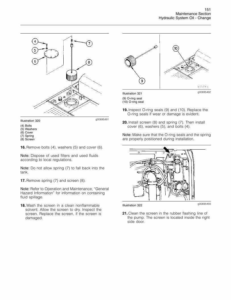
g00695491Illustration 320
(4) Bolts(5) Washers(6) Cover(7) Spring(8) Screen
16. Remove bolts (4), washers (5) and cover (6).
Note: Dispose of used filters and used fluidsaccording to local regulations.
Note: Do not allow spring (7) to fall back into thetank.
17. Remove spring (7) and screen (8).
Note: Refer to Operation and Maintenance, “GeneralHazard Information” for information on containingfluid spillage.
18. Wash the screen in a clean nonflammablesolvent. Allow the screen to dry. Inspect thescreen. Replace the screen, if the screen isdamaged.
g00695492Illustration 321
(9) O-ring seal(10) O-ring seal
19. Inspect O-ring seals (9) and (10). Replace theO-ring seals if wear or damage is evident.
20. Install screen (8) and spring (7). Then installcover (6), washers (5), and bolts (4).
Note: Make sure that the O-ring seals and the springare properly positioned during installation.
g00695493Illustration 322
21. Clean the screen in the rubber flashing line ofthe pump. The screen is located inside the rightside door.
152Maintenance SectionHydraulic System Oil - Change
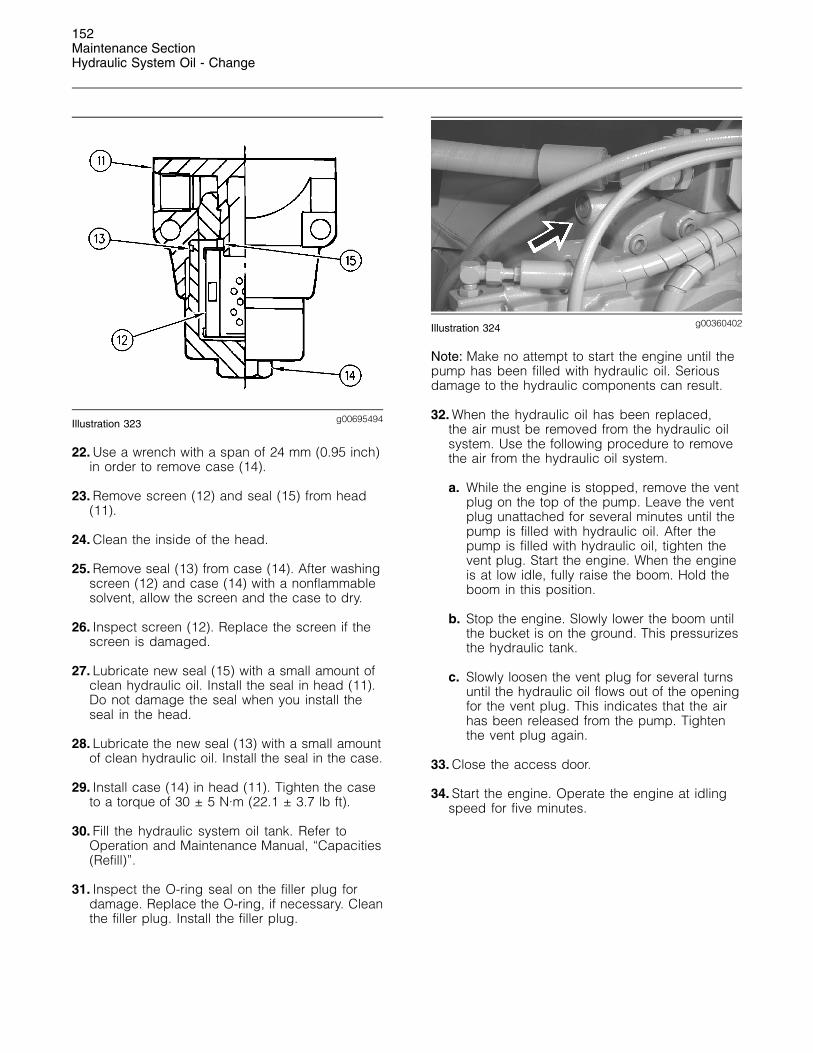
g00695494Illustration 323
22. Use a wrench with a span of 24 mm (0.95 inch)in order to remove case (14).
23. Remove screen (12) and seal (15) from head(11).
24. Clean the inside of the head.
25. Remove seal (13) from case (14). After washingscreen (12) and case (14) with a nonflammablesolvent, allow the screen and the case to dry.
26. Inspect screen (12). Replace the screen if thescreen is damaged.
27. Lubricate new seal (15) with a small amount ofclean hydraulic oil. Install the seal in head (11).Do not damage the seal when you install theseal in the head.
28. Lubricate the new seal (13) with a small amountof clean hydraulic oil. Install the seal in the case.
29. Install case (14) in head (11). Tighten the caseto a torque of 30 ± 5 N·m (22.1 ± 3.7 lb ft).
30. Fill the hydraulic system oil tank. Refer toOperation and Maintenance Manual, “Capacities(Refill)”.
31. Inspect the O-ring seal on the filler plug fordamage. Replace the O-ring, if necessary. Cleanthe filler plug. Install the filler plug.
g00360402Illustration 324
Note: Make no attempt to start the engine until thepump has been filled with hydraulic oil. Seriousdamage to the hydraulic components can result.
32. When the hydraulic oil has been replaced,the air must be removed from the hydraulic oilsystem. Use the following procedure to removethe air from the hydraulic oil system.
a. While the engine is stopped, remove the ventplug on the top of the pump. Leave the ventplug unattached for several minutes until thepump is filled with hydraulic oil. After thepump is filled with hydraulic oil, tighten thevent plug. Start the engine. When the engineis at low idle, fully raise the boom. Hold theboom in this position.
b. Stop the engine. Slowly lower the boom untilthe bucket is on the ground. This pressurizesthe hydraulic tank.
c. Slowly loosen the vent plug for several turnsuntil the hydraulic oil flows out of the openingfor the vent plug. This indicates that the airhas been released from the pump. Tightenthe vent plug again.
33. Close the access door.
34. Start the engine. Operate the engine at idlingspeed for five minutes.
153Maintenance Section
Hydraulic System Oil Filter (Return) - Replace
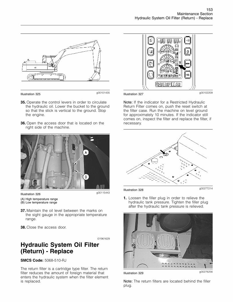
g00101435Illustration 325
35. Operate the control levers in order to circulatethe hydraulic oil. Lower the bucket to the groundso that the stick is vertical to the ground. Stopthe engine.
36. Open the access door that is located on theright side of the machine.
g00115443Illustration 326
(A) High temperature range(B) Low temperature range
37. Maintain the oil level between the marks onthe sight gauge in the appropriate temperaturerange.
38. Close the access door.
i01961629
Hydraulic System Oil Filter(Return) - ReplaceSMCS Code: 5068-510-RJ
The return filter is a cartridge type filter. The returnfilter reduces the amount of foreign material thatenters the hydraulic system when the filter elementis replaced.
g00102209Illustration 327
Note: If the indicator for a Restricted HydraulicReturn Filter comes on, push the reset switch atthe filter case. Run the machine on level groundfor approximately 10 minutes. If the indicator stillcomes on, inspect the filter and replace the filter, ifnecessary.
g00277214Illustration 328
1. Loosen the filler plug in order to relieve thehydraulic tank pressure. Tighten the filler plugafter the hydraulic tank pressure is relieved.
g00276256Illustration 329
Note: The return filters are located behind the fillerplug.
154Maintenance SectionHydraulic System Oil Filter (Return) - Replace
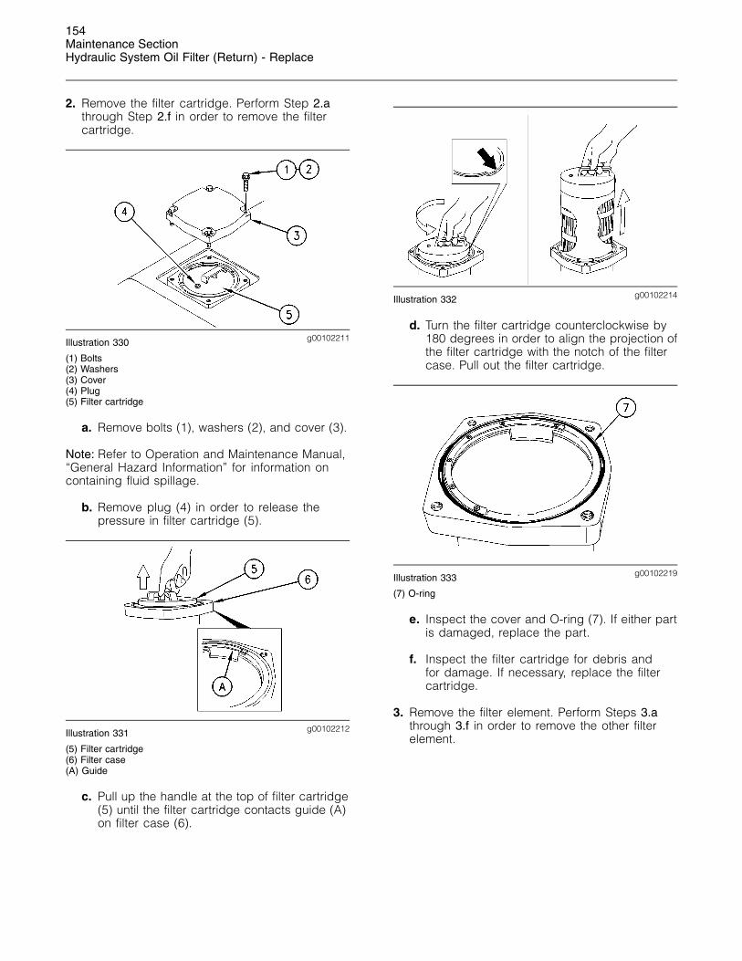
2. Remove the filter cartridge. Perform Step 2.athrough Step 2.f in order to remove the filtercartridge.
g00102211Illustration 330
(1) Bolts(2) Washers(3) Cover(4) Plug(5) Filter cartridge
a. Remove bolts (1), washers (2), and cover (3).
Note: Refer to Operation and Maintenance Manual,“General Hazard Information” for information oncontaining fluid spillage.
b. Remove plug (4) in order to release thepressure in filter cartridge (5).
g00102212Illustration 331
(5) Filter cartridge(6) Filter case(A) Guide
c. Pull up the handle at the top of filter cartridge(5) until the filter cartridge contacts guide (A)on filter case (6).
g00102214Illustration 332
d. Turn the filter cartridge counterclockwise by180 degrees in order to align the projection ofthe filter cartridge with the notch of the filtercase. Pull out the filter cartridge.
g00102219Illustration 333
(7) O-ring
e. Inspect the cover and O-ring (7). If either partis damaged, replace the part.
f. Inspect the filter cartridge for debris andfor damage. If necessary, replace the filtercartridge.
3. Remove the filter element. Perform Steps 3.athrough 3.f in order to remove the other filterelement.
155Maintenance Section
Hydraulic System Oil Filter (Return) - Replace
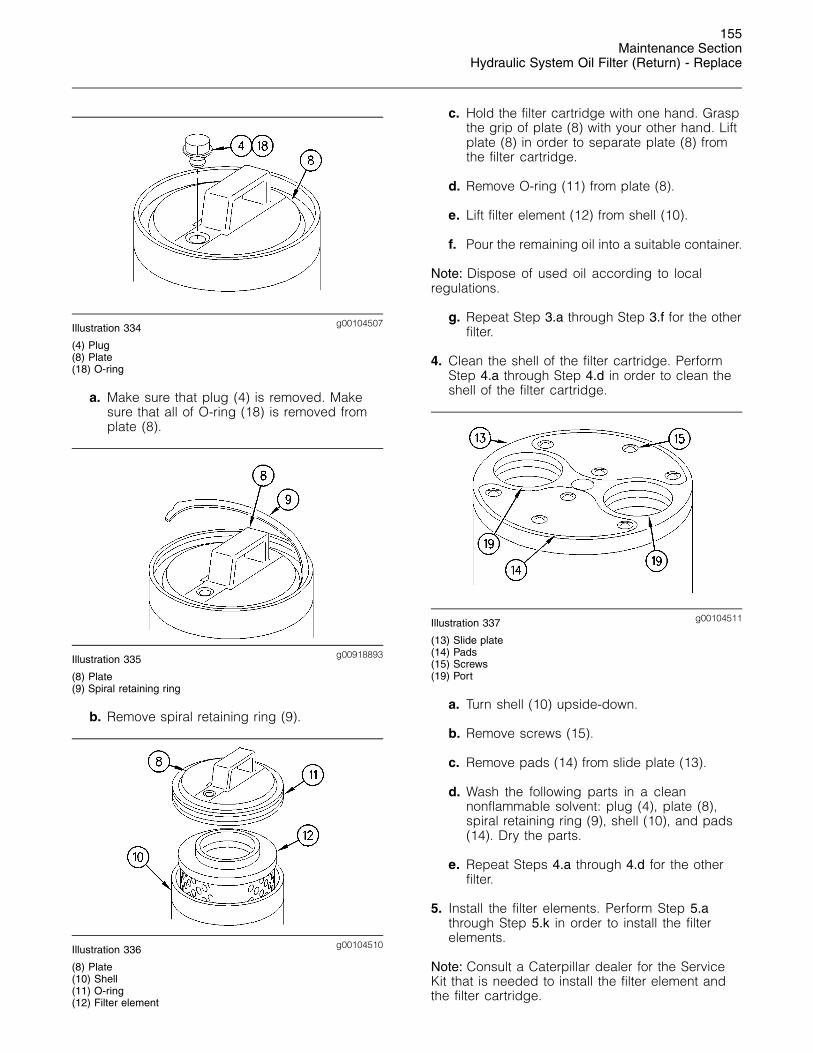
g00104507Illustration 334
(4) Plug(8) Plate(18) O-ring
a. Make sure that plug (4) is removed. Makesure that all of O-ring (18) is removed fromplate (8).
g00918893Illustration 335
(8) Plate(9) Spiral retaining ring
b. Remove spiral retaining ring (9).
g00104510Illustration 336
(8) Plate(10) Shell(11) O-ring(12) Filter element
c. Hold the filter cartridge with one hand. Graspthe grip of plate (8) with your other hand. Liftplate (8) in order to separate plate (8) fromthe filter cartridge.
d. Remove O-ring (11) from plate (8).
e. Lift filter element (12) from shell (10).
f. Pour the remaining oil into a suitable container.
Note: Dispose of used oil according to localregulations.
g. Repeat Step 3.a through Step 3.f for the otherfilter.
4. Clean the shell of the filter cartridge. PerformStep 4.a through Step 4.d in order to clean theshell of the filter cartridge.
g00104511Illustration 337
(13) Slide plate(14) Pads(15) Screws(19) Port
a. Turn shell (10) upside-down.
b. Remove screws (15).
c. Remove pads (14) from slide plate (13).
d. Wash the following parts in a cleannonflammable solvent: plug (4), plate (8),spiral retaining ring (9), shell (10), and pads(14). Dry the parts.
e. Repeat Steps 4.a through 4.d for the otherfilter.
5. Install the filter elements. Perform Step 5.athrough Step 5.k in order to install the filterelements.
Note: Consult a Caterpillar dealer for the ServiceKit that is needed to install the filter element andthe filter cartridge.
156Maintenance SectionHydraulic System Oil Filter (Return) - Replace
a. Apply spray type oil to the inside of shell (10)in order to prevent rust.
b. Apply grease to a new O-ring (11).
c. Plate (8) will contact the inside of shell (10).Apply grease to this point.
d. Apply grease to O-rings inside ports (19) atthe bottom of shell (10).
e. Install new pads (14). Tighten screws to atorque of 4 N·m (35 lb in).
f. Apply spray type oil into the clearancebetween shell (10) and slide plate (13).
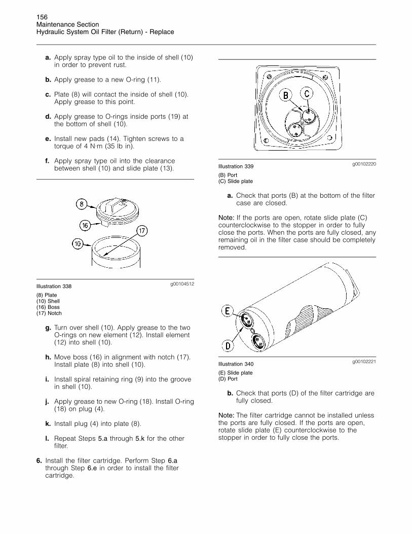
g00104512Illustration 338
(8) Plate(10) Shell(16) Boss(17) Notch
g. Turn over shell (10). Apply grease to the twoO-rings on new element (12). Install element(12) into shell (10).
h. Move boss (16) in alignment with notch (17).Install plate (8) into shell (10).
i. Install spiral retaining ring (9) into the groovein shell (10).
j. Apply grease to new O-ring (18). Install O-ring(18) on plug (4).
k. Install plug (4) into plate (8).
l. Repeat Steps 5.a through 5.k for the otherfilter.
6. Install the filter cartridge. Perform Step 6.athrough Step 6.e in order to install the filtercartridge.
g00102220Illustration 339
(B) Port(C) Slide plate
a. Check that ports (B) at the bottom of the filtercase are closed.
Note: If the ports are open, rotate slide plate (C)counterclockwise to the stopper in order to fullyclose the ports. When the ports are fully closed, anyremaining oil in the filter case should be completelyremoved.
g00102221Illustration 340
(E) Slide plate(D) Port
b. Check that ports (D) of the filter cartridge arefully closed.
Note: The filter cartridge cannot be installed unlessthe ports are fully closed. If the ports are open,rotate slide plate (E) counterclockwise to thestopper in order to fully close the ports.
157Maintenance Section
Hydraulic System Oil Filter - Replace
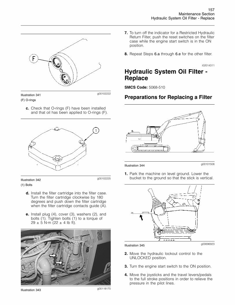
g00102222Illustration 341
(F) O-rings
c. Check that O-rings (F) have been installedand that oil has been applied to O-rings (F).
g00102225Illustration 342
(1) Bolts
d. Install the filter cartridge into the filter case.Turn the filter cartridge clockwise by 180degrees and push down the filter cartridgewhen the filter cartridge contacts guide (A).
e. Install plug (4), cover (3), washers (2), andbolts (1). Tighten bolts (1) to a torque of29 ± 5 N·m (22 ± 4 lb ft).
g00118170Illustration 343
7. To turn off the indicator for a Restricted HydraulicReturn Filter, push the reset switches on the filtercase while the engine start switch is in the ONposition.
8. Repeat Steps 6.a through 6.e for the other filter.
i02014311
Hydraulic System Oil Filter -ReplaceSMCS Code: 5068-510
Preparations for Replacing a Filter
g00101508Illustration 344
1. Park the machine on level ground. Lower thebucket to the ground so that the stick is vertical.
g00696923Illustration 345
2. Move the hydraulic lockout control to theUNLOCKED position.
3. Turn the engine start switch to the ON position.
4. Move the joysticks and the travel levers/pedalsto the full stroke positions in order to relieve thepressure in the pilot lines.
158Maintenance SectionHydraulic System Oil Filter - Replace
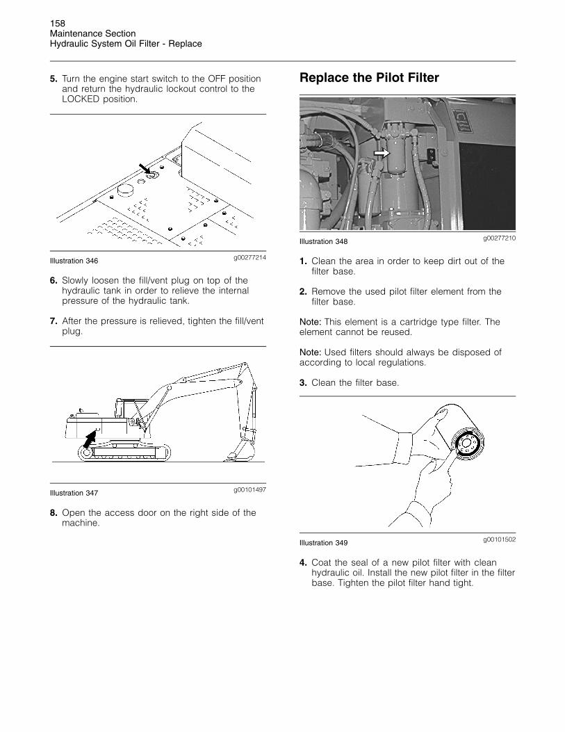
5. Turn the engine start switch to the OFF positionand return the hydraulic lockout control to theLOCKED position.
g00277214Illustration 346
6. Slowly loosen the fill/vent plug on top of thehydraulic tank in order to relieve the internalpressure of the hydraulic tank.
7. After the pressure is relieved, tighten the fill/ventplug.
g00101497Illustration 347
8. Open the access door on the right side of themachine.
Replace the Pilot Filter
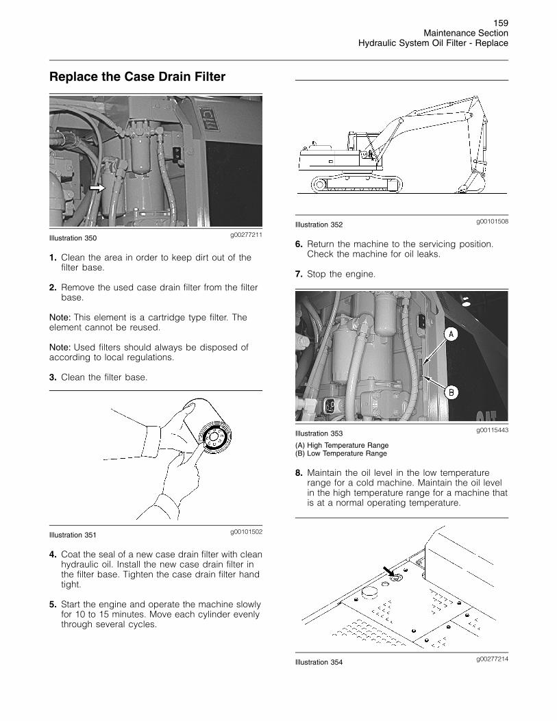
g00277210Illustration 348
1. Clean the area in order to keep dirt out of thefilter base.
2. Remove the used pilot filter element from thefilter base.
Note: This element is a cartridge type filter. Theelement cannot be reused.
Note: Used filters should always be disposed ofaccording to local regulations.
3. Clean the filter base.
g00101502Illustration 349
4. Coat the seal of a new pilot filter with cleanhydraulic oil. Install the new pilot filter in the filterbase. Tighten the pilot filter hand tight.
159Maintenance Section
Hydraulic System Oil Filter - Replace
Replace the Case Drain Filter
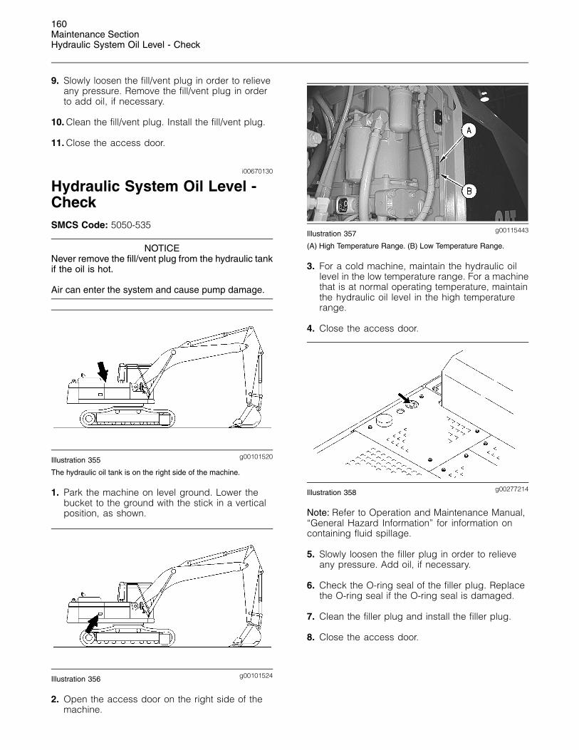
g00277211Illustration 350
1. Clean the area in order to keep dirt out of thefilter base.
2. Remove the used case drain filter from the filterbase.
Note: This element is a cartridge type filter. Theelement cannot be reused.
Note: Used filters should always be disposed ofaccording to local regulations.
3. Clean the filter base.
g00101502Illustration 351
4. Coat the seal of a new case drain filter with cleanhydraulic oil. Install the new case drain filter inthe filter base. Tighten the case drain filter handtight.
5. Start the engine and operate the machine slowlyfor 10 to 15 minutes. Move each cylinder evenlythrough several cycles.
g00101508Illustration 352
6. Return the machine to the servicing position.Check the machine for oil leaks.
7. Stop the engine.
g00115443Illustration 353
(A) High Temperature Range(B) Low Temperature Range
8. Maintain the oil level in the low temperaturerange for a cold machine. Maintain the oil levelin the high temperature range for a machine thatis at a normal operating temperature.
g00277214Illustration 354
160Maintenance SectionHydraulic System Oil Level - Check
9. Slowly loosen the fill/vent plug in order to relieveany pressure. Remove the fill/vent plug in orderto add oil, if necessary.
10. Clean the fill/vent plug. Install the fill/vent plug.
11. Close the access door.
i00670130
Hydraulic System Oil Level -CheckSMCS Code: 5050-535
NOTICENever remove the fill/vent plug from the hydraulic tankif the oil is hot.
Air can enter the system and cause pump damage.
g00101520Illustration 355
The hydraulic oil tank is on the right side of the machine.
1. Park the machine on level ground. Lower thebucket to the ground with the stick in a verticalposition, as shown.
g00101524Illustration 356
2. Open the access door on the right side of themachine.
g00115443Illustration 357
(A) High Temperature Range. (B) Low Temperature Range.
3. For a cold machine, maintain the hydraulic oillevel in the low temperature range. For a machinethat is at normal operating temperature, maintainthe hydraulic oil level in the high temperaturerange.
4. Close the access door.
g00277214Illustration 358
Note: Refer to Operation and Maintenance Manual,“General Hazard Information” for information oncontaining fluid spillage.
5. Slowly loosen the filler plug in order to relieveany pressure. Add oil, if necessary.
6. Check the O-ring seal of the filler plug. Replacethe O-ring seal if the O-ring seal is damaged.
7. Clean the filler plug and install the filler plug.
8. Close the access door.
161Maintenance Section
Hydraulic System Oil Sample - Obtain
i02013736
Hydraulic System Oil Sample- ObtainSMCS Code: 5050-008-OC; 5095-008; 5095-SM;
7542-008; 7542
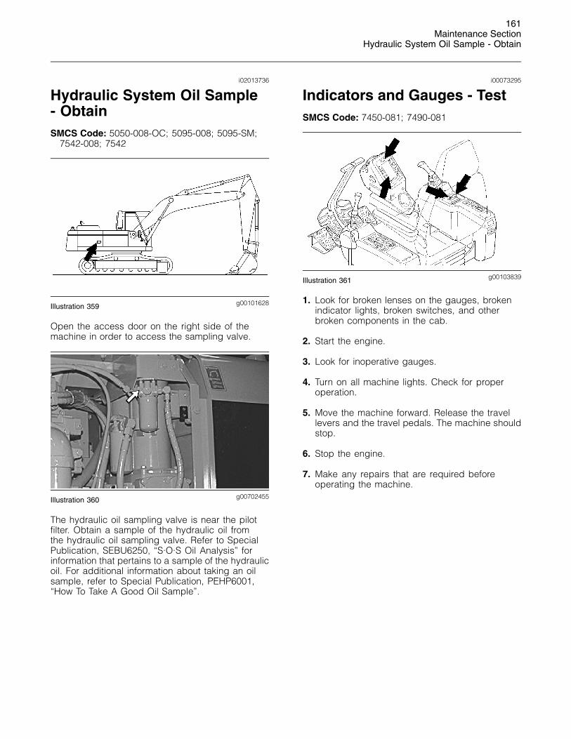
g00101628Illustration 359
Open the access door on the right side of themachine in order to access the sampling valve.
g00702455Illustration 360
The hydraulic oil sampling valve is near the pilotfilter. Obtain a sample of the hydraulic oil fromthe hydraulic oil sampling valve. Refer to SpecialPublication, SEBU6250, “S·O·S Oil Analysis” forinformation that pertains to a sample of the hydraulicoil. For additional information about taking an oilsample, refer to Special Publication, PEHP6001,“How To Take A Good Oil Sample”.
i00073295
Indicators and Gauges - TestSMCS Code: 7450-081; 7490-081
g00103839Illustration 361
1. Look for broken lenses on the gauges, brokenindicator lights, broken switches, and otherbroken components in the cab.
2. Start the engine.
3. Look for inoperative gauges.
4. Turn on all machine lights. Check for properoperation.
5. Move the machine forward. Release the travellevers and the travel pedals. The machine shouldstop.
6. Stop the engine.
7. Make any repairs that are required beforeoperating the machine.
162Maintenance SectionOil Filter - Inspect
i01719384
Oil Filter - InspectSMCS Code: 1308-507; 5068-507
Inspect a Used Filter for Debris
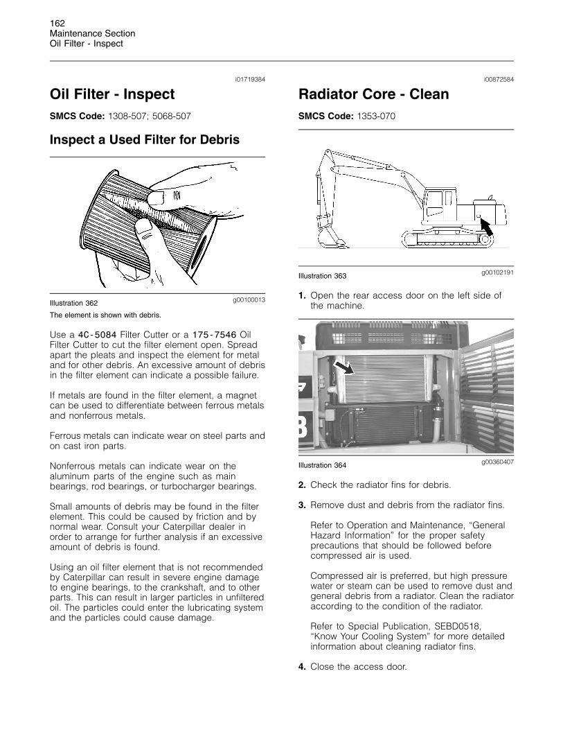
g00100013Illustration 362
The element is shown with debris.
Use a 4C-5084 Filter Cutter or a 175-7546 OilFilter Cutter to cut the filter element open. Spreadapart the pleats and inspect the element for metaland for other debris. An excessive amount of debrisin the filter element can indicate a possible failure.
If metals are found in the filter element, a magnetcan be used to differentiate between ferrous metalsand nonferrous metals.
Ferrous metals can indicate wear on steel parts andon cast iron parts.
Nonferrous metals can indicate wear on thealuminum parts of the engine such as mainbearings, rod bearings, or turbocharger bearings.
Small amounts of debris may be found in the filterelement. This could be caused by friction and bynormal wear. Consult your Caterpillar dealer inorder to arrange for further analysis if an excessiveamount of debris is found.
Using an oil filter element that is not recommendedby Caterpillar can result in severe engine damageto engine bearings, to the crankshaft, and to otherparts. This can result in larger particles in unfilteredoil. The particles could enter the lubricating systemand the particles could cause damage.
i00872584
Radiator Core - CleanSMCS Code: 1353-070
g00102191Illustration 363
1. Open the rear access door on the left side ofthe machine.
g00360407Illustration 364
2. Check the radiator fins for debris.
3. Remove dust and debris from the radiator fins.
Refer to Operation and Maintenance, “GeneralHazard Information” for the proper safetyprecautions that should be followed beforecompressed air is used.
Compressed air is preferred, but high pressurewater or steam can be used to remove dust andgeneral debris from a radiator. Clean the radiatoraccording to the condition of the radiator.
Refer to Special Publication, SEBD0518,“Know Your Cooling System” for more detailedinformation about cleaning radiator fins.
4. Close the access door.
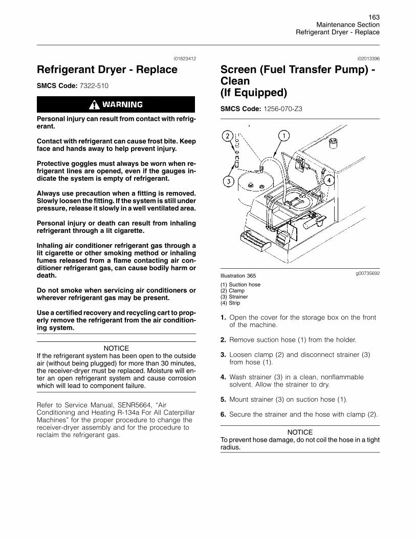
163Maintenance Section
Refrigerant Dryer - Replace
i01823412
Refrigerant Dryer - ReplaceSMCS Code: 7322-510
Personal injury can result from contact with refrig-erant.
Contact with refrigerant can cause frost bite. Keepface and hands away to help prevent injury.
Protective goggles must always be worn when re-frigerant lines are opened, even if the gauges in-dicate the system is empty of refrigerant.
Always use precaution when a fitting is removed.Slowly loosen the fitting. If the system is still underpressure, release it slowly in a well ventilated area.
Personal injury or death can result from inhalingrefrigerant through a lit cigarette.
Inhaling air conditioner refrigerant gas through alit cigarette or other smoking method or inhalingfumes released from a flame contacting air con-ditioner refrigerant gas, can cause bodily harm ordeath.
Do not smoke when servicing air conditioners orwherever refrigerant gas may be present.
Use a certified recovery and recycling cart to prop-erly remove the refrigerant from the air condition-ing system.
NOTICEIf the refrigerant system has been open to the outsideair (without being plugged) for more than 30 minutes,the receiver-dryer must be replaced. Moisture will en-ter an open refrigerant system and cause corrosionwhich will lead to component failure.
Refer to Service Manual, SENR5664, “AirConditioning and Heating R-134a For All CaterpillarMachines” for the proper procedure to change thereceiver-dryer assembly and for the procedure toreclaim the refrigerant gas.
i02013396
Screen (Fuel Transfer Pump) -Clean(If Equipped)SMCS Code: 1256-070-Z3
g00735692Illustration 365
(1) Suction hose(2) Clamp(3) Strainer(4) Strip
1. Open the cover for the storage box on the frontof the machine.
2. Remove suction hose (1) from the holder.
3. Loosen clamp (2) and disconnect strainer (3)from hose (1).
4. Wash strainer (3) in a clean, nonflammablesolvent. Allow the strainer to dry.
5. Mount strainer (3) on suction hose (1).
6. Secure the strainer and the hose with clamp (2).
NOTICETo prevent hose damage, do not coil the hose in a tightradius.
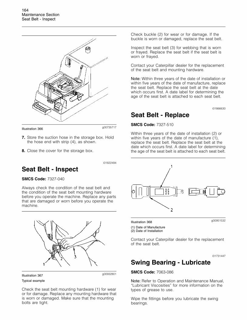
164Maintenance SectionSeat Belt - Inspect
g00735717Illustration 366
7. Store the suction hose in the storage box. Holdthe hose end with strip (4), as shown.
8. Close the cover for the storage box.
i01822494
Seat Belt - InspectSMCS Code: 7327-040
Always check the condition of the seat belt andthe condition of the seat belt mounting hardwarebefore you operate the machine. Replace any partsthat are damaged or worn before you operate themachine.
g00932801Illustration 367
Typical example
Check the seat belt mounting hardware (1) for wearor for damage. Replace any mounting hardware thatis worn or damaged. Make sure that the mountingbolts are tight.
Check buckle (2) for wear or for damage. If thebuckle is worn or damaged, replace the seat belt.
Inspect the seat belt (3) for webbing that is wornor frayed. Replace the seat belt if the seat belt isworn or frayed.
Contact your Caterpillar dealer for the replacementof the seat belt and mounting hardware.
Note: Within three years of the date of installation orwithin five years of the date of manufacture, replacethe seat belt. Replace the seat belt at the datewhich occurs first. A date label for determining theage of the seat belt is attached to each seat belt.
i01866630
Seat Belt - ReplaceSMCS Code: 7327-510
Within three years of the date of installation (2) orwithin five years of the date of manufacture (1),replace the seat belt. Replace the seat belt at thedate which occurs first. A date label for determiningthe age of the seat belt is attached to each seat belt.
g00951532Illustration 368
(1) Date of Manufacture(2) Date of Installation
Contact your Caterpillar dealer for the replacementof the seat belt.
i01731447
Swing Bearing - LubricateSMCS Code: 7063-086
Note: Refer to Operation and Maintenance Manual,“Lubricant Viscosities” for more information on thetypes of grease to use.
Wipe the fittings before you lubricate the swingbearings.
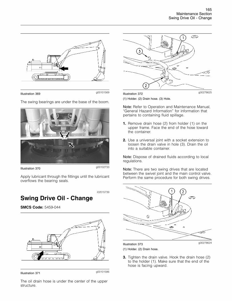
165Maintenance Section
Swing Drive Oil - Change
g00101569Illustration 369
The swing bearings are under the base of the boom.
g00102733Illustration 370
Apply lubricant through the fittings until the lubricantoverflows the bearing seals.
i02015739
Swing Drive Oil - ChangeSMCS Code: 5459-044
g00101586Illustration 371
The oil drain hose is under the center of the upperstructure.
g00278625Illustration 372
(1) Holder. (2) Drain hose. (3) Hole.
Note: Refer to Operation and Maintenance Manual,“General Hazard Information” for information thatpertains to containing fluid spillage.
1. Remove drain hose (2) from holder (1) on theupper frame. Face the end of the hose towardthe container.
2. Use a universal joint with a socket extension toloosen the drain valve in hole (3). Drain the oilinto a suitable container.
Note: Dispose of drained fluids according to localregulations.
Note: There are two swing drives that are locatedbetween the swivel joint and the main control valve.Perform the same procedure for both swing drives.
g00278624Illustration 373
(1) Holder. (2) Drain hose.
3. Tighten the drain valve. Hook the drain hose (2)to the holder (1). Make sure that the end of thehose is facing upward.
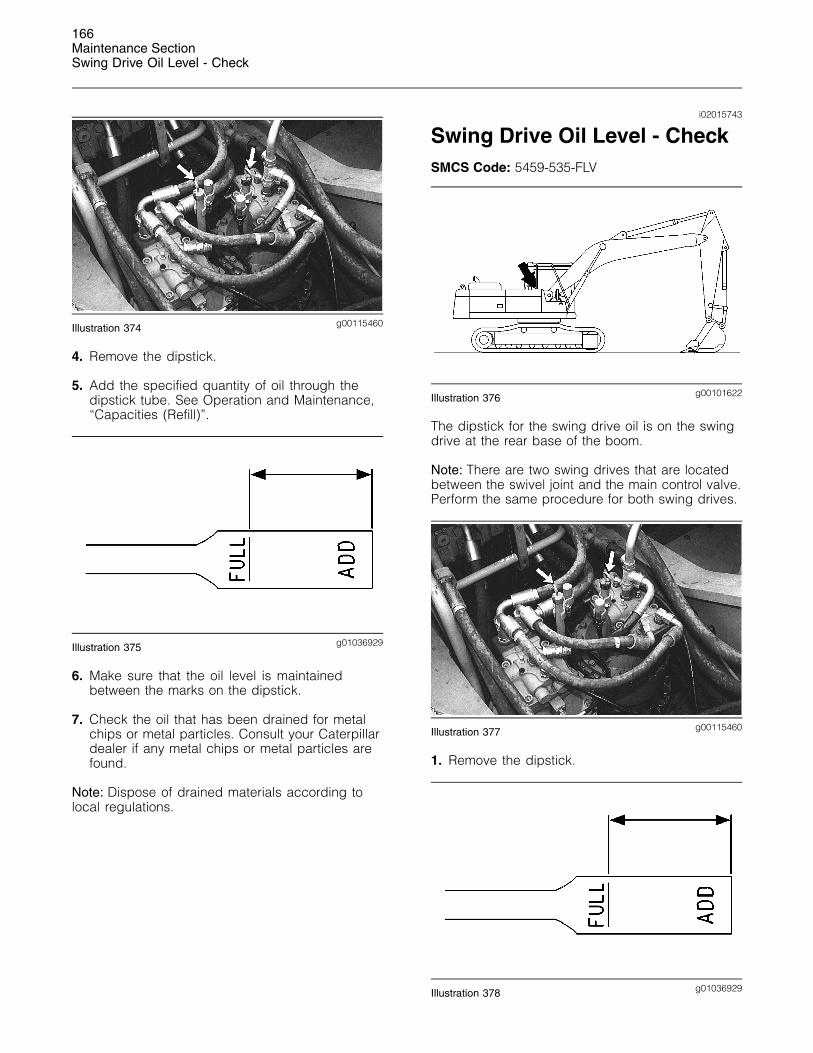
166Maintenance SectionSwing Drive Oil Level - Check
g00115460Illustration 374
4. Remove the dipstick.
5. Add the specified quantity of oil through thedipstick tube. See Operation and Maintenance,“Capacities (Refill)”.
g01036929Illustration 375
6. Make sure that the oil level is maintainedbetween the marks on the dipstick.
7. Check the oil that has been drained for metalchips or metal particles. Consult your Caterpillardealer if any metal chips or metal particles arefound.
Note: Dispose of drained materials according tolocal regulations.
i02015743
Swing Drive Oil Level - CheckSMCS Code: 5459-535-FLV
g00101622Illustration 376
The dipstick for the swing drive oil is on the swingdrive at the rear base of the boom.
Note: There are two swing drives that are locatedbetween the swivel joint and the main control valve.Perform the same procedure for both swing drives.
g00115460Illustration 377
1. Remove the dipstick.
g01036929Illustration 378
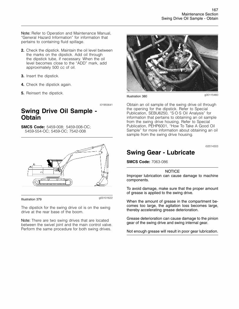
167Maintenance Section
Swing Drive Oil Sample - Obtain
Note: Refer to Operation and Maintenance Manual,“General Hazard Information” for information thatpertains to containing fluid spillage.
2. Check the dipstick. Maintain the oil level betweenthe marks on the dipstick. Add oil throughthe dipstick tube, if necessary. When the oillevel becomes close to the “ADD” mark, addapproximately 500 cc of oil.
3. Insert the dipstick.
4. Check the dipstick again.
5. Reinsert the dipstick.
i01955641
Swing Drive Oil Sample -ObtainSMCS Code: 5459-008; 5459-008-OC;
5459-554-OC; 5459-OC; 7542-008
g00101622Illustration 379
The dipstick for the swing drive oil is on the swingdrive at the rear base of the boom.
Note: There are two swing drives that are locatedbetween the swivel joint and the main control valve.Perform the same procedure for both swing drives.
g00115460Illustration 380
Obtain an oil sample of the swing drive oil throughthe opening for the dipstick. Refer to SpecialPublication, SEBU6250, “S·O·S Oil Analysis” forinformation that pertains to obtaining an oil samplefrom the swing drive housing. Refer to SpecialPublication, PEHP6001, “How To Take A Good OilSample” for more information about obtaining an oilsample from the swing drive housing.
i02014303
Swing Gear - LubricateSMCS Code: 7063-086
NOTICEImproper lubrication can cause damage to machinecomponents.
To avoid damage, make sure that the proper amountof grease is applied to the swing drive.
When the amount of grease in the compartment be-comes too large, the agitation loss becomes large,thereby accelerating grease deterioration.
Grease deterioration can cause damage to the piniongear of the swing drive and swing internal gear.
Not enough grease will result in poor gear lubrication.
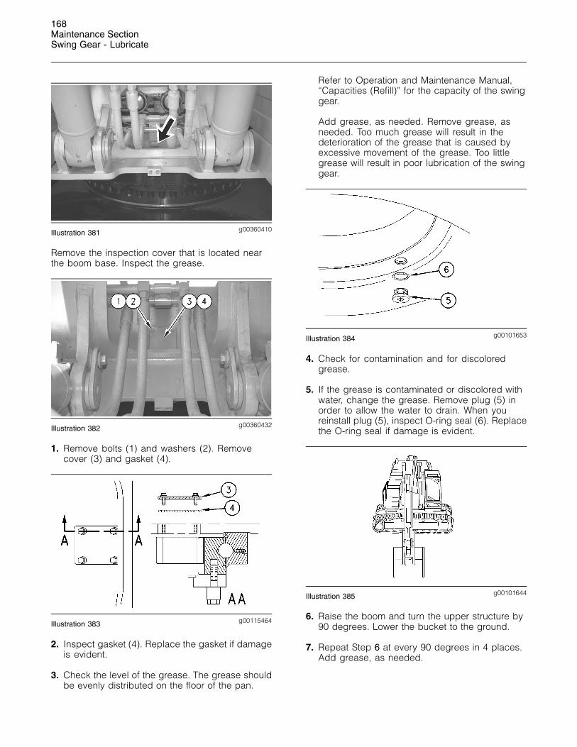
168Maintenance SectionSwing Gear - Lubricate
g00360410Illustration 381
Remove the inspection cover that is located nearthe boom base. Inspect the grease.
g00360432Illustration 382
1. Remove bolts (1) and washers (2). Removecover (3) and gasket (4).
g00115464Illustration 383
2. Inspect gasket (4). Replace the gasket if damageis evident.
3. Check the level of the grease. The grease shouldbe evenly distributed on the floor of the pan.
Refer to Operation and Maintenance Manual,“Capacities (Refill)” for the capacity of the swinggear.
Add grease, as needed. Remove grease, asneeded. Too much grease will result in thedeterioration of the grease that is caused byexcessive movement of the grease. Too littlegrease will result in poor lubrication of the swinggear.
g00101653Illustration 384
4. Check for contamination and for discoloredgrease.
5. If the grease is contaminated or discolored withwater, change the grease. Remove plug (5) inorder to allow the water to drain. When youreinstall plug (5), inspect O-ring seal (6). Replacethe O-ring seal if damage is evident.
g00101644Illustration 385
6. Raise the boom and turn the upper structure by90 degrees. Lower the bucket to the ground.
7. Repeat Step 6 at every 90 degrees in 4 places.Add grease, as needed.
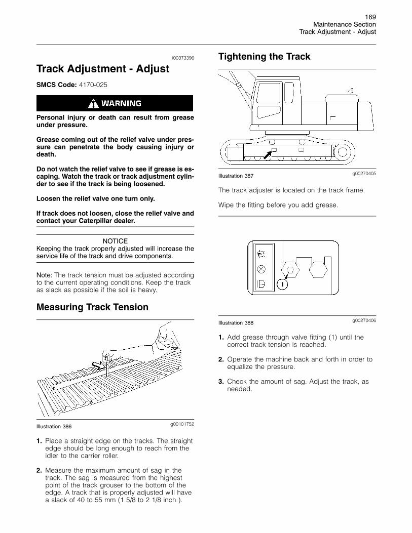
169Maintenance Section
Track Adjustment - Adjust
i00373396
Track Adjustment - AdjustSMCS Code: 4170-025
Personal injury or death can result from greaseunder pressure.
Grease coming out of the relief valve under pres-sure can penetrate the body causing injury ordeath.
Do not watch the relief valve to see if grease is es-caping. Watch the track or track adjustment cylin-der to see if the track is being loosened.
Loosen the relief valve one turn only.
If track does not loosen, close the relief valve andcontact your Caterpillar dealer.
NOTICEKeeping the track properly adjusted will increase theservice life of the track and drive components.
Note: The track tension must be adjusted accordingto the current operating conditions. Keep the trackas slack as possible if the soil is heavy.
Measuring Track Tension
g00101752Illustration 386
1. Place a straight edge on the tracks. The straightedge should be long enough to reach from theidler to the carrier roller.
2. Measure the maximum amount of sag in thetrack. The sag is measured from the highestpoint of the track grouser to the bottom of theedge. A track that is properly adjusted will havea slack of 40 to 55 mm (1 5/8 to 2 1/8 inch ).
Tightening the Track
g00270405Illustration 387
The track adjuster is located on the track frame.
Wipe the fitting before you add grease.
g00270406Illustration 388
1. Add grease through valve fitting (1) until thecorrect track tension is reached.
2. Operate the machine back and forth in order toequalize the pressure.
3. Check the amount of sag. Adjust the track, asneeded.
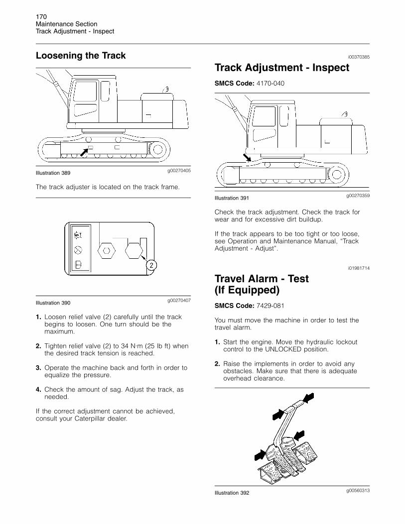
170Maintenance SectionTrack Adjustment - Inspect
Loosening the Track
g00270405Illustration 389
The track adjuster is located on the track frame.
g00270407Illustration 390
1. Loosen relief valve (2) carefully until the trackbegins to loosen. One turn should be themaximum.
2. Tighten relief valve (2) to 34 N·m (25 lb ft) whenthe desired track tension is reached.
3. Operate the machine back and forth in order toequalize the pressure.
4. Check the amount of sag. Adjust the track, asneeded.
If the correct adjustment cannot be achieved,consult your Caterpillar dealer.
i00370385
Track Adjustment - InspectSMCS Code: 4170-040
g00270359Illustration 391
Check the track adjustment. Check the track forwear and for excessive dirt buildup.
If the track appears to be too tight or too loose,see Operation and Maintenance Manual, “TrackAdjustment - Adjust”.
i01981714
Travel Alarm - Test(If Equipped)SMCS Code: 7429-081
You must move the machine in order to test thetravel alarm.
1. Start the engine. Move the hydraulic lockoutcontrol to the UNLOCKED position.
2. Raise the implements in order to avoid anyobstacles. Make sure that there is adequateoverhead clearance.
g00560313Illustration 392
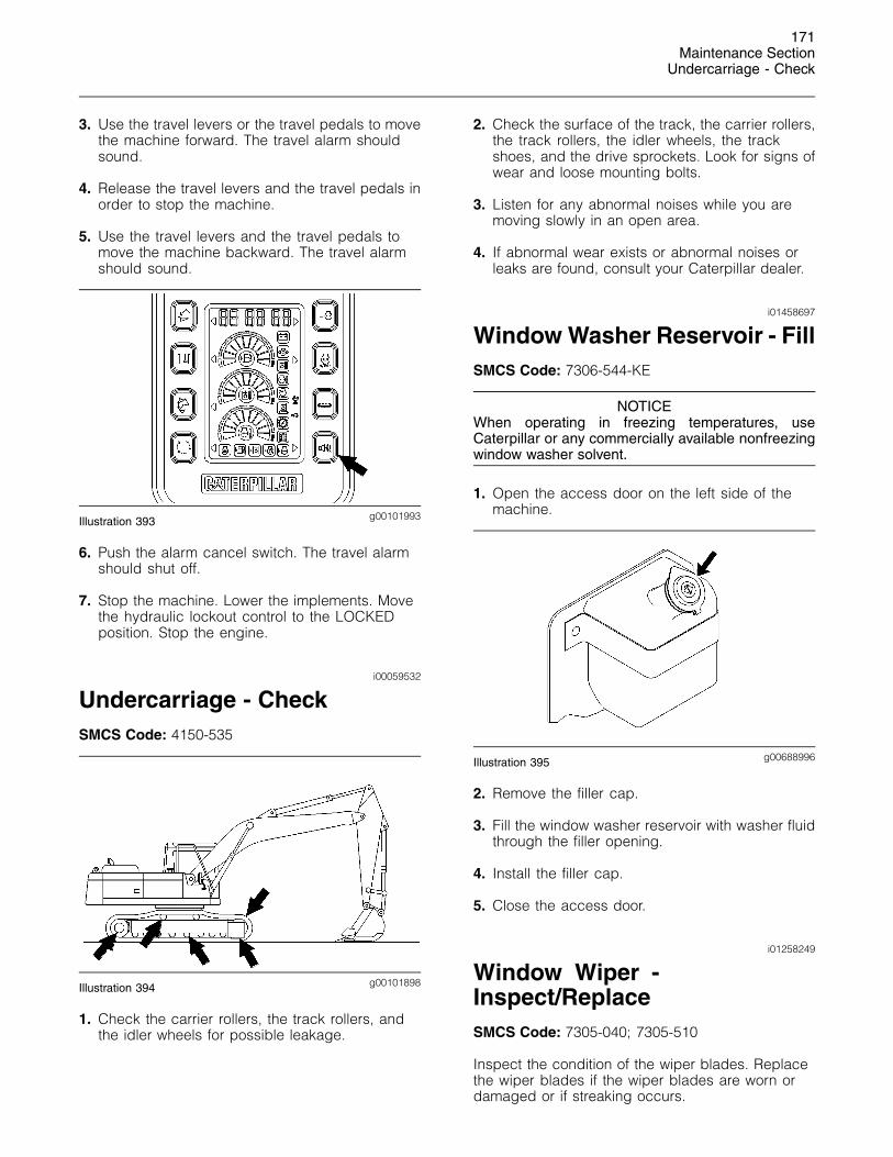
171Maintenance Section
Undercarriage - Check
3. Use the travel levers or the travel pedals to movethe machine forward. The travel alarm shouldsound.
4. Release the travel levers and the travel pedals inorder to stop the machine.
5. Use the travel levers and the travel pedals tomove the machine backward. The travel alarmshould sound.
g00101993Illustration 393
6. Push the alarm cancel switch. The travel alarmshould shut off.
7. Stop the machine. Lower the implements. Movethe hydraulic lockout control to the LOCKEDposition. Stop the engine.
i00059532
Undercarriage - CheckSMCS Code: 4150-535
g00101898Illustration 394
1. Check the carrier rollers, the track rollers, andthe idler wheels for possible leakage.
2. Check the surface of the track, the carrier rollers,the track rollers, the idler wheels, the trackshoes, and the drive sprockets. Look for signs ofwear and loose mounting bolts.
3. Listen for any abnormal noises while you aremoving slowly in an open area.
4. If abnormal wear exists or abnormal noises orleaks are found, consult your Caterpillar dealer.
i01458697
Window Washer Reservoir - FillSMCS Code: 7306-544-KE
NOTICEWhen operating in freezing temperatures, useCaterpillar or any commercially available nonfreezingwindow washer solvent.
1. Open the access door on the left side of themachine.
g00688996Illustration 395
2. Remove the filler cap.
3. Fill the window washer reservoir with washer fluidthrough the filler opening.
4. Install the filler cap.
5. Close the access door.
i01258249
Window Wiper -Inspect/ReplaceSMCS Code: 7305-040; 7305-510
Inspect the condition of the wiper blades. Replacethe wiper blades if the wiper blades are worn ordamaged or if streaking occurs.
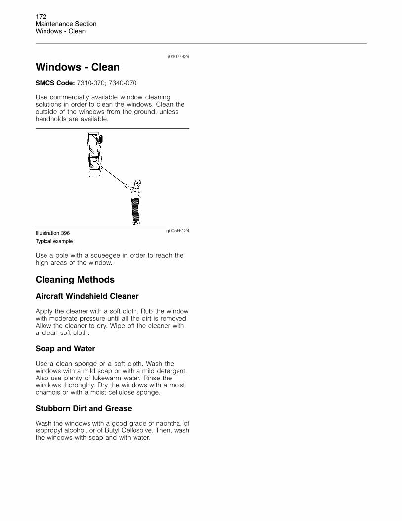
172Maintenance SectionWindows - Clean
i01077829
Windows - CleanSMCS Code: 7310-070; 7340-070
Use commercially available window cleaningsolutions in order to clean the windows. Clean theoutside of the windows from the ground, unlesshandholds are available.
g00566124Illustration 396
Typical example
Use a pole with a squeegee in order to reach thehigh areas of the window.
Cleaning Methods
Aircraft Windshield Cleaner
Apply the cleaner with a soft cloth. Rub the windowwith moderate pressure until all the dirt is removed.Allow the cleaner to dry. Wipe off the cleaner witha clean soft cloth.
Soap and Water
Use a clean sponge or a soft cloth. Wash thewindows with a mild soap or with a mild detergent.Also use plenty of lukewarm water. Rinse thewindows thoroughly. Dry the windows with a moistchamois or with a moist cellulose sponge.
Stubborn Dirt and Grease
Wash the windows with a good grade of naphtha, ofisopropyl alcohol, or of Butyl Cellosolve. Then, washthe windows with soap and with water.