Embed Size (px)
Citation preview
©2003 CaterpillarAll Rights Reserved
Printed in U.S.A.
RENR5437-02June 2003
330C ExcavatorHydraulic SystemCYA1-UPHAA1-UPMCA1-UPJAB1-UPKDD1-UPGAG1-UP
GKX1-UPDKY1-UP
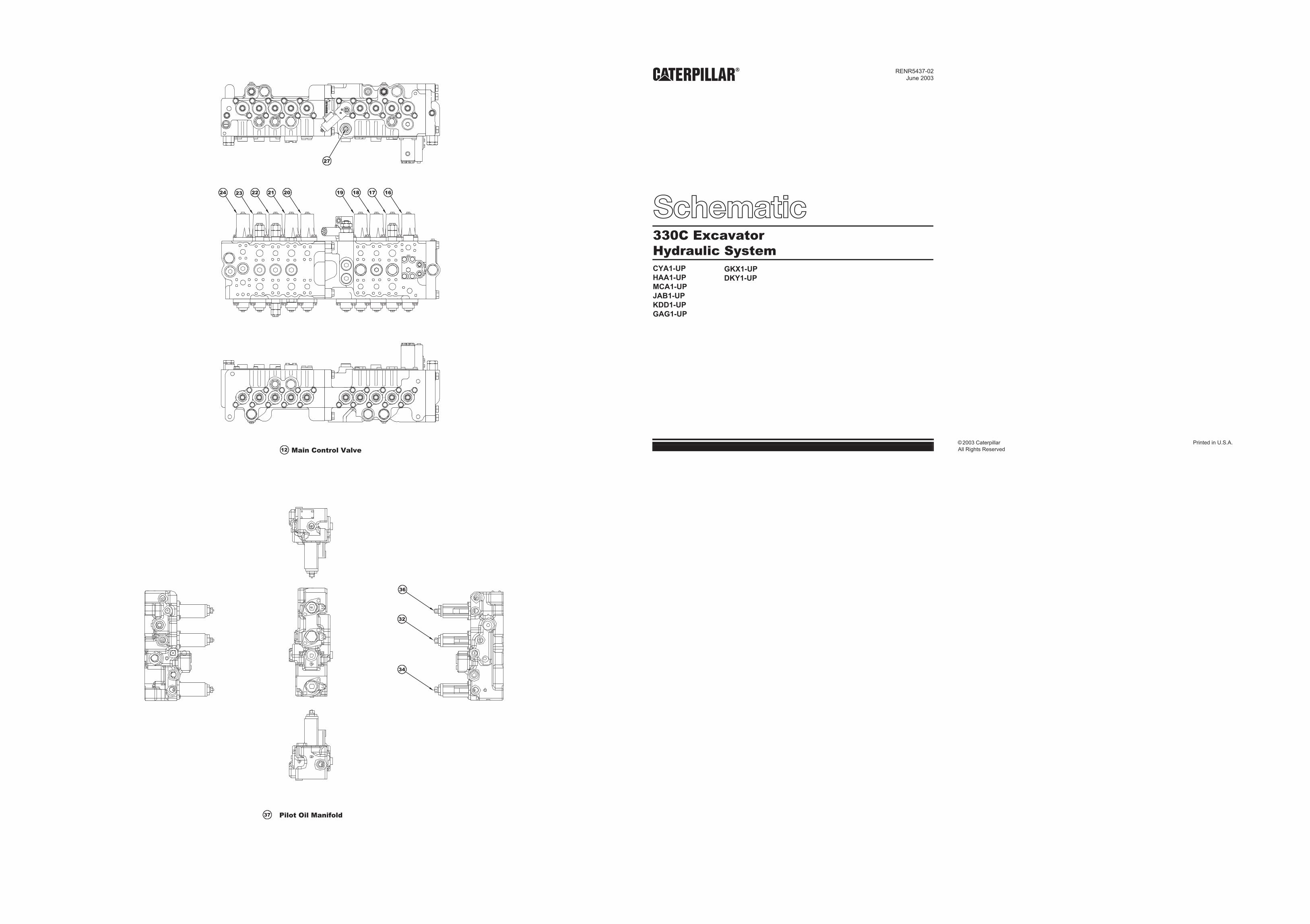
12 Main Control Valve
24 23 22 21 20 19 18 17 16
27
36
32
34
37 Pilot Oil Manifold
IN
T
OUT
BDr
Pi2A3
M1
M2
J2
J1
R3
A2
A1
M3
X2
X1
R2
S
S4A4
T2
B A
T1
T2
T1
A B
X X
TOUTPIN
PACPi1P2P1 PSA2
DR6DR5
PSA1
DR4DR3DR2DR1
PR
C
D
D
C
BA
G
F E
BP1 BT
(LOWER)
(OUT)
(IN)
T
(RAISE)
(REV)
(FWD)(R) (OPEN)
(CLOSE)
(L)
(FWD)
(REV)
P1P2
B2
A2 B1
B8B7B6C B5B4B3B2B1
A8A7A6A5A4A3A2A1
SDr
STSP1
SP2
Pi3 Di3 DST
(IN)
PRPL(OUT)
AR4R1BR4
AR3BR3AR2BR2
SPi
SP3
(RAISE)
AR1BR1
BR5Di4
Pi4
AL1
bL3
AR5AL4
BL1
CLO
SE
AL2
OP
EN
A1
R3BL2
BPi
AL3
DO
WN
R2
BP3
LR
R4
BP2
X3
bR4
aR5Pi1aR4
bR5HR
Di1
aR3
bR3
aR2
bR2
aR1
bR1
aL1
bL1HL
aL2
bL2bL4 Pi2
aL4
Di2
IN UP
R1
OU
T
M4
BL3aL3
AB
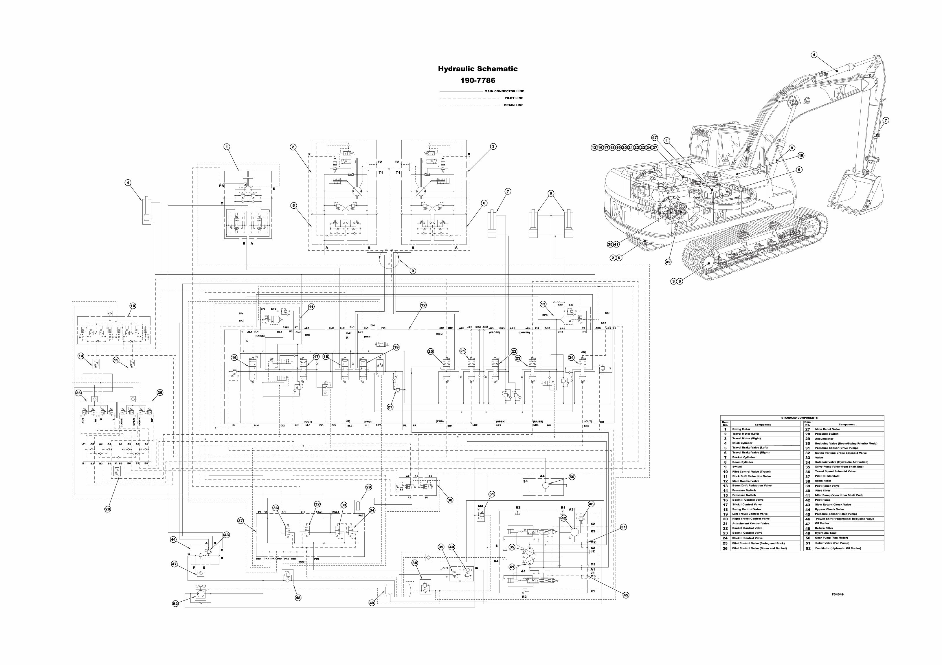
ItemComponent
STANDARD COMPONENTS
ComponentNo.ItemNo.
123456789
1011121314151617181920212223242526
Swing Motor
Travel Motor (Left)
Travel Motor (Right)
Stick Cylinder
2728293031323334353637383940414243444546474849505152
Hydraulic Tank
Gear Pump (Fan Motor)
Relief Valve (Fan Pump)
Fan Motor (Hydraulic Oil Cooler)
Return Filter
Oil Cooler
Pressure Sensor (Idler Pump)
Bypass Check Valve
Slow Return Check Valve
Pilot Pump
Idler Pump (View from Shaft End)
Pilot Filter
Pilot Relief Valve
Drain Filter
Pilot Oil Manifold
Travel Speed Solenoid Valve
Drive Pump (View from Shaft End)
Solenoid Valve (Hydraulic Activation) Valve
Swing Parking Brake Solenoid Valve
Pressure Sensor (Drive Pump) Reducing Valve (Boom/Swing Priority Mode)
Accumulator
Pressure Switch
Main Relief Valve
Pilot Control Valve (Boom and Bucket)
Pilot Control Valve (Swing and Stick)
Stick II Control Valve
Boom I Control Valve
Bucket Control Valve
Attachment Control Valve
Right Travel Control Valve
Left Travel Control Valve
Swing Control Valve
Stick I Control Valve
Boom II Control Valve
Pressure Switch
Pressure Switch
Boom Drift Reduction Valve Main Control Valve
Stick Drift Reduction Valve
Pilot Control Valve (Travel)
Swivel
Boom Cylinder
Bucket Cylinder
Travel Brake Valve (Right)
Travel Brake Valve (Left)
Power Shift Proportional Reducing Valve
MAIN CONNECTOR LINE
PILOT LINE
DRAIN LINE
Hydraulic Schematic190-7786
1 2
5
3
7 8
9
10 11 12 13
1415
16 17 18
1920 21 22
23 24
25 26
27
28
47
4443
52
3632 33
34
29
4849
38
39 40
3051
50
42
41
35
41
31
45
4
7
8
9
1
12 16 17 1918 20 21 22 23 24 27
42
49
52
63
4135
4
F04649
47
46
37
6