Embed Size (px)
Citation preview

PROJECT REPORT
2nd Project on Damage Stability for
RoRo Passenger ships
Final Report Authors: Tryggve Ahlman, Swedish Shipowners’ Association Jan Bergholtz, Kattegatt Design AB Ana Sanz, Kattegatt Design AB Martin Schreuder, Chalmers University of Technology Ronnie Hanzén, Swedish Transport Agency Project No: TRV 2017/61982 Swedish Transport Administration SjöV 150620 Swedish Maritime Administration
____________________________________________________ 31 JANUARY 2018
Doc. No.: TRV 2017/61982-RP-001 Project: 2:nd RoPax DamStab Project Subject: Final Project Report Resp.: Tryggve Ahlman
Rev.: 00 Date: 2018-01-31 Page: - 1 (38) - Author: Various
SUMMARY
Ro-ro passenger ship services constitute an important part of the European maritime infrastructure, and indeed play a crucial role for Sweden in connecting seaborne transport routes to and from our neighbouring countries. Moreover, northern European countries have been leading the development of, not only the ro-ro passenger ship concept as such, but also the development of relevant safety standards for this fleet. Understandably, it is therefore crucial for the Swedish maritime sector to take part of the legislative process that covers a significant share of the Swedish maritime infrastructure.
Thus, in light of the IMO deliberations on the revisions of Chapter II-1 of the SOLAS Convention in general and proposals for an increased safety standard for passenger ships in particular, a first Triple-Helix project, partly funded by the Swedish Maritime Administration, was mobilized by the Swedish Shipowners’ Association, focusing on ro-ro passenger ship safety from a holistic perspective. The conclusions and findings of this Project can be found in the Report “Damage Stability Project for RoRo Passenger Ships – Final Report” [1.].
As the draft proposals for enhanced safety standards for passenger ships materialised into firm amendments to SOLAS Chapter II-1, which have now been adopted by the Marine Safety Committee of the International Maritime Organization during its 98th session, an extension of the Damage Stability Project was granted additional funding in the beginning of 2017 and consequently the 2nd Project on Damage Stability for Ro-Ro Passenger Ships (2nd RoPax DamStab Project) was mobilised.
The aim of the 2nd RoPax DamStab Project has been to review and evaluate existing as well as future ro-ro passenger ship safety regulations from a theoretical perspective, with the objectives to:
1. provide in-depth knowledge about and facilitate the understanding of existing as well as future damage stability standards,
2. facilitate understanding of ship type specific characteristics from a safety standard aspect, and
3. assess the consequences for the ro-ro passenger ship fleet.
This report outlines the work and findings of the 2nd RoPax DamStab Project as performed during the year of 2017.
00 2018-01-31 For Information Tryggve Ahlman
Rev Date Revision Issued by Checked by Approved by
DOCUMENT REVISION RECORD
Doc. No.: TRV 2017/61982-RP-001 Project: 2:nd RoPax DamStab Project Subject: Final Project Report Resp.: Tryggve Ahlman
Rev.: 00 Date: 2018-01-31 Page: 0 (35) Author: Various
Doc. No: TRV 2017/61982-RP-001
ACKNOWLEDGEMENTS
The authors would like to express their gratitude to the Swedish Maritime Administration for granting financial support to the project as outlined herein.

Doc. No.: TRV 2017/61982-RP-001 Project: 2:nd RoPax DamStab Project Subject: Final Project Report Resp.: Tryggve Ahlman
Rev.: 00 Date: 2018-01-31 Page: 1 (35) Author: Various
Doc. No: TRV 2017/61982-RP-001
0 OVERALL CONCLUSIONS AND FINDINGS
0.1 Establishment of State of Play
Ro-ro passenger ships are conceptually different from other types of passenger ships. In addition to passenger accommodation and recreational areas this ship type is characterised by large vehicle decks designed for the carriage of rolling cargo which impose an increased risk, should water ingress occur resulting in large free surfaces on these decks. The additional risk stemming from the conceptual nature of these ships is to large extent mitigated by some 20 ship type specific requirements, including design and operational aspects. In addition, for ships serving European trades compliance must be demonstrated also with the requirements of Directive 2003/25/EC, [6.], hereinafter referred to the Stockholm Agreement, which are aiming at mitigation of the risk for and consequences of water ingress onto the vehicle deck, see chapter 2.2.
When now SOLAS Convention is again subject to revision, hereinafter referred to as SOLAS 2020, amendments to the calculation procedures of the survivability factor si for ro-ro passenger ships have been agreed and adopted, aiming at providing an equivalent safety standard from “Water on Deck”, WOD, perspective when compared to the requirements as stipulated in Directive 2003/25/EC. Hence, in addition to a significant raise in index R, as per the entry into force of SOLAS 2020, ro-ro passenger ships are subjected also to the need for further investments in “survivability factor” enhancement measures in order to attain an acceptable attained subdivision index A.
While the WOD-mechanism of the Stockholm Agreement is directly related to the residual freeboard, the WOD-mechanism as introduced in the amended Regulation 7.2 of SOLAS 2020 is based on the characteristics of the GZ-curve up to 20 degrees. Hence, it can be presumed that the outcome of the new WOD-mechanism will be related to the metacentric height, GM, rather than to the residual freeboard.
Moreover, the operational aspects of the Stockholm Agreement, in terms of the maximum significant wave height representing the geographical area in which the ship is allowed to operate, are not given any consideration in the adopted amendments of the SOLAS Convention.
Despite the IMO efforts to include a WOD-mechanism in the methodology for calculating the survivability factor si, it has been indicated by EC that for ships trading between EU ports, compliance must still be demonstrated also with regard to the Stockholm Agreement as it is prescribed in Directive 2003/25/EC. Hence, since the damage assumptions and associated stability requirements of the directive are in fact based upon the deterministic approach as stipulated in SOLAS 1990, it seems likely to envisage that also future European ro-ro passenger ship designs must in principle be subdivided in accordance with the deterministic principles preceding the probabilistic approach.

Doc. No.: TRV 2017/61982-RP-001 Project: 2:nd RoPax DamStab Project Subject: Final Project Report Resp.: Tryggve Ahlman
Rev.: 00 Date: 2018-01-31 Page: 2 (35) Author: Various
Doc. No: TRV 2017/61982-RP-001
0.2 Damage Stability Assessments
The hydrostatic damage stability assessments as performed within the 2nd DamStab Project and outlined in this report are based upon a hydrostatic model representing an existing ro-ro passenger ship, the Project Ship, designed for compliance with the relevant stability regulations of SOLAS 2009 and the Directive 2003/25/EC (the so-called Stockholm Agreement). For the purpose of the evaluation of different regulations, and moreover the effect of different Risk Control Options, RCO:s, aiming at the mitigation of the risk for and consequences of water ingress on the vehicle deck, the parameter minimum metacentric height, GMmin, as required for fulfilment of the respective requirements, has been used as the basis for comparisons.
Following quite an extensive debate on an adequate safety standard for passenger ships, a substantial increase in terms of the required subdivision index R was adopted by the IMO Maritime Safety Committee at its 98th session. For the Project Ship, the new definition of index R, as stipulated in Regulation 6 of the adopted amendments to SOLAS II-1, results in a 3% relative increase when compared to the existing Regulation. In addition, the adopted WOD-mechanism as introduced in Regulation 7.2 of the adopted amendments to the Convention reduces the attained subdivision index A by another 2.4%.
A comparison between the GMmin-values for compliance with Regulation 7 as stipulated in SOLAS 2009 and the forthcoming SOLAS 2020 respectively reveals that, for the Project Ship, a significant increase in GMmin (0.150m) is required. Nevertheless, even though Regulation 7 of SOLAS 2020 could possibly be considered as equivalent, from GMmin point of view, to the requirements of Stockholm Agreement at light load line and at partial load line, equivalence seems to be far from achievable at the summer load line when the freeboard is minimum.
However, for the Project Ship, the deterministic stability requirements of Regulation 9, pertinent to prescriptive bottom damages, governs by far, the overall minimum allowable metacentric height, GMmin, in particular for the light and partial load lines, see Figure below.
dL
dP
dS
0.00
0.20
0.40
0.60
0.80
1.00
1.20
1.40
1.60
1.80
2.00
2.20
2.40
5.00 5.10 5.20 5.30 5.40 5.50 5.60 5.70 5.80 5.90 6.00 6.10 6.20 6.30 6.40
Min
imu
m A
llow
able
GM
[m]
Draught [m]
SOLAS 2020 + SAGMmin
Reg. 9 SA SOLAS 2020 Reg. 7 Reg. 8.2 SOLAS 2009 Reg. 7 Reg. 8.1

Doc. No.: TRV 2017/61982-RP-001 Project: 2:nd RoPax DamStab Project Subject: Final Project Report Resp.: Tryggve Ahlman
Rev.: 00 Date: 2018-01-31 Page: 3 (35) Author: Various
Doc. No: TRV 2017/61982-RP-001
0.3 Assessments of Risk Control Options
Following the entry into force of the Stockholm Agreement, the arrangement of transverse barriers on the vehicle deck has proven to be an effective means to mitigate the consequences of water ingress onto the ro-ro deck. Another risk control option, that would mitigate the risk for capsize when water ingress on the vehicle deck has occurred following a collision damage, is the arrangement of wide watertight side casings. Hence, the respective effect of these RCO:s on the outcome of damage stability calculations has been assessed in terms of influence on the minimum allowable metacentric height, GMmin, for compliance both with Stockholm Agreement and with SOLAS 2020.
Even though both investigated risk control options render a significant reduction in required GMmin for the summer load line draught, when evaluated against the requirements of Stockholm Agreement, the effect of seems not to be recognised by the WOD-mechanism as introduced in the adopted Regulation 7.2 of SOLAS 2020.
0.4 In-depth Assessments of RCO2 – Wide Side Casings
A study has been done where the side casing width of an example ship have been systematically varied in order to assess the impact of water tight side casings as a risk control option for damaged RoPax ships. A two- and a three-compartment damage have been investigated through damage stability calculations in accordance with SOLAS 2009 and SOLAS 2020 as well as time domain numerical simulations.
The time domain simulations reveal that the arrangement of wide side casings will effectively mitigate the risk for capsize when the investigated ship is exposed to the “worst” two- and three-compartment damage cases. The configuration of 2.0 m wide side casings showed no capsizes for the respective two- and three-compartment damage case within the stipulated 180 minutes (3 hours) simulation time in any of the simulated significant wave heights, amounting up to 4.0m.
Moreover, when compared to the outcome of hydrostatic damage stability calculations the findings of this study indicate that the regulations underestimate the strength of the trend of increasing survivability with increased side casing width.

Doc. No.: TRV 2017/61982-RP-001 Project: 2:nd RoPax DamStab Project Subject: Final Project Report Resp.: Tryggve Ahlman
Rev.: 00 Date: 2018-01-31 Page: 4 (35) Author: Various
Doc. No: TRV 2017/61982-RP-001
0.5 Dissemination
The Project has been represented during and has actively participated in the following activities:
2015-Jun-03-12 IMO, 95th session of the Maritime Safety Committee, MSC 95, IMO Headquarters, London
2016-Jan-18-22 IMO, 3rd session of the Sub-committee on Ship Design and Construction, SDC 3, IMO Headquarters, London
2016-Feb-01-05 IMO, 3rd session of the Sub-committee on Human Element, Training and Watchkeeping, HTW 3, IMO Headquarters, London
2016-May-11-20 IMO, 96th session of the Maritime Safety Committee, MSC 96, IMO Headquarters, London
2016-Nov-21-25 IMO, 97th session of the Maritime Safety Committee, MSC 97, IMO Headquarters, London
2017-Jan-30-03 IMO, 4th session of the Sub-committee on Human Element, Training and Watchkeeping, HTW 4, IMO Headquarters, London
2017-Feb-13-17 IMO, 4rd session of the Sub-committee on Ship Design and Construction, SDC 4, IMO Headquarters, London
2017-Jun-07-16 IMO, 98th session of the Maritime Safety Committee, MSC 98, IMO Headquarters, London
2016-Feb-Dec IMO, SDS (Subdivision and Damage Stability) Correspondence Group, tasked to review and propose draft Explanatory Notes for SOLAS Chapter II-1
2017-Feb-Dec IMO, SDS (Subdivision and Damage Stability) Correspondence Group, tasked to develop draft amendments to SOLAS regulation II-1/8-1 including functional and performance requirements in order to improve the availability of passenger ships' electrical power supply in cases of flooding from side raking damage.
2017-Feb-Dec IMO, SDS (Subdivision and Damage Stability) Correspondence Group, tasked to finalize the draft guidelines on stability computers and shore-based support for passenger ships constructed before 1 January 2014.
2016-2017 As adviser to the Swedish Transport Agency, contributing to the deliberations on the Required Subdivision Index R

Doc. No.: TRV 2017/61982-RP-001 Project: 2:nd RoPax DamStab Project Subject: Final Project Report Resp.: Tryggve Ahlman
Rev.: 00 Date: 2018-01-31 Page: 5 (35) Author: Various
Doc. No: TRV 2017/61982-RP-001
CONTENTS SUMMARY ACKNOWLEDGEMENTS
0 OVERALL CONCLUSIONS AND FINDINGS.......................................................................... 1 0.1 Establishment of State of Play ................................................................................................. 1 0.2 Damage Stability Assessments................................................................................................. 2 0.3 Assessments of Risk Control Options....................................................................................... 3 0.4 In-depth Assessments of RCO2 – Wide Side Casings ............................................................... 3 0.5 Dissemination .......................................................................................................................... 4 1 PREAMBLE ..................................................................................................................... 7 1.1 Background .............................................................................................................................. 7 1.2 Objectives ................................................................................................................................ 7 1.3 Project Organization ................................................................................................................ 7 2 ESTABLISHMENT OF STATE OF PLAY ................................................................................ 8 2.1 The International Convention for the Safety of Life at Sea (SOLAS) ........................................ 8 2.1.1 Stability Standards for Passenger Ships in General ................................................................. 8 2.1.2 SOLAS 2009 Chapter II-1 Part B Regulation 6 – Required Subdivision Index R ........................ 9 2.1.3 SOLAS 2009 Chapter II-1 Part B Regulation 7 – Attained Subdivision Index A ...................... 11 2.1.4 SOLAS 2009 Chapter II-1 Part B Regulation 8 – Special Requirements concerning Passenger
Ship Stability........................................................................................................................... 12 2.1.5 SOLAS 2009 Chapter II-1 Part B Regulation 9 – Double Bottoms in Passenger Ships and
Cargo Ships other than Tankers ............................................................................................. 12 2.1.6 Specific Requirements for Ro-Ro Passenger Ships ................................................................ 13 2.2 Directive 2003/25/EC (the Stockholm Agreement) ............................................................... 14 3 DAMAGE STABILITY ASSESSMENTS ................................................................................ 16 3.1 Purpose of Assessments ........................................................................................................ 16 3.2 Selected Project Ship ............................................................................................................. 17 3.3 Validation of Hydrostatic Model and Stability Calculations .................................................. 18 3.3.1 Validation of General Hydrostatic Data ................................................................................. 18 3.3.2 Calculation of Required Subdivision Index, R ........................................................................ 19 3.3.3 Recalculation of Attained Subdivision Index A at GMmin for compliance with Reg. 6 ........... 19 3.3.4 Validation of Stockholm Agreement Calculations ................................................................. 19 3.3.5 Basis for Assessment - GMmin ................................................................................................. 20 3.4 General Assessment of SOLAS Chapter II-1 Regulation 7 - Attained Subdivision Index A ..... 21 3.4.1 Influence of Trim in the calculation of Attained Subdivision Index A .................................... 21 3.4.2 Influence of Hydrostatic Model and Software tolerances on the calculation of the
Survivability Factor si ............................................................................................................. 21 3.5 Assessment of SOLAS 2020 Chapter II-1 Regulation 6 ........................................................... 22 3.6 Assessment of SOLAS 2020 Chapter II-1 Regulation 7 ........................................................... 22 3.6.1 Influence of the SOLAS 2020 Chapter II-1 Regulation 7.2 WOD-mechanism ........................ 22 3.6.2 Assessment of the full Scope of SOLAS 2020 Chapter II-1 Regulation 7................................ 22

Doc. No.: TRV 2017/61982-RP-001 Project: 2:nd RoPax DamStab Project Subject: Final Project Report Resp.: Tryggve Ahlman
Rev.: 00 Date: 2018-01-31 Page: 6 (35) Author: Various
Doc. No: TRV 2017/61982-RP-001
4 ASSESSMENT OF RISK CONTROL OPTIONS, RCO:S, INTENDED TO MITIGATE THE CONSEQUENCES OF WATER ON DECK ............................................................................ 24
4.1 RCO1 – Transverse Barriers on Vehicle Deck ......................................................................... 24 4.1.1 Influence on the fulfilment of the requirements of Stockholm Agreement.......................... 24 4.1.2 Influence on the fulfilment of the requirements of SOLAS 2020 .......................................... 25 4.2 RCO2 - Wide Side Casings ...................................................................................................... 25 4.2.1 Influence on the fulfilment of the requirements of Stockholm Agreement.......................... 26 4.2.2 Influence on the fulfilment of the requirements of SOLAS 2020 .......................................... 26 4.3 Conclusions on the arrangement of RCO:s from hydrostatic perspective ............................ 27 5 IN-DEPTH ASSESSMENT OF RCO2 – WIDE SIDE CASINGS ................................................. 28 5.1 Introduction ........................................................................................................................... 28 5.1 Background ............................................................................................................................ 28 5.2 Set-up of the study................................................................................................................. 29 5.3 Results .................................................................................................................................... 30 5.4 Discussion/conclusions .......................................................................................................... 34 6 REFERENCES .................................................................................................................. 35

Doc. No.: TRV 2017/61982-RP-001 Project: 2:nd RoPax DamStab Project Subject: Final Project Report Resp.: Tryggve Ahlman
Rev.: 00 Date: 2018-01-31 Page: 7 (35) Author: Various
Doc. No: TRV 2017/61982-RP-001
1 PREAMBLE
1.1 Background
Ro-ro passenger ship services constitute an important part of the European maritime infrastructure, and indeed play a crucial role for Sweden in connecting seaborne transport routes to and from our neighbouring countries. Moreover, northern European countries have been leading the development of, not only the ro-ro passenger ship concept as such, but also the development of relevant safety standards for this fleet. Understandably, it is therefore crucial for the Swedish maritime sector to take part of the legislative process that covers a significant share of the Swedish maritime infrastructure.
Thus, in light of the IMO deliberations on the revisions of Chapter II-1 of the SOLAS Convention in general and proposals for an increased safety standard for passenger ships in particular, a first Triple-Helix project, partly funded by the Swedish Maritime Administration, was mobilised by the Swedish Shipowners’ Association, focusing on ro-ro passenger ship safety from a holistic perspective. The conclusions and findings of this Project can be found in the Report “Damage Stability Project for RoRo Passenger Ships – Final Report” [1.].
As the draft proposals for enhanced safety standards for passenger ships materialised into firm amendments to SOLAS Chapter II-1, which have now been adopted by the Marine Safety Committee of the International Maritime Organization during its 98th session, an extension of the Damage Stability Project was granted additional funding in the beginning of 2017 and consequently the 2nd Project on Damage Stability for Ro-Ro Passenger Ships (2nd RoPax DamStab Project) was mobilised.
1.2 Objectives
The aim of the 2nd RoPax DamStab Project has been to review and evaluate existing as well as future ro-ro passenger ship safety regulations from a theoretical perspective, with the objectives to:
1. provide in-depth knowledge about and facilitate the understanding of existing as well as future damage stability standards,
2. facilitate understanding of ship type specific characteristics from a safety standard aspect, and
3. assess the consequences for the ro-ro passenger ship fleet.
1.3 Project Organization
The Project has been performed as a Triple-Helix project, involving Authority, Academia and Industry representatives. The following partners have actively participated in the execution of the scope:
Authority: Swedish Transport Agency (Ronnie Hanzén)
Academia: Chalmers University of Technology (Martin Schreuder)
Industry Partners: Swedish Shipowners’ Association (Tryggve Ahlman)
Kattegatt Design AB (Jan Bergholtz)
(Ana Sanz)
Reference Partner: Rederi AB Eckerö (Sten Rosenqvist)
Reference Partner: Stena Teknik (Per Wimby)

Doc. No.: TRV 2017/61982-RP-001 Project: 2:nd RoPax DamStab Project Subject: Final Project Report Resp.: Tryggve Ahlman
Rev.: 00 Date: 2018-01-31 Page: 8 (35) Author: Various
Doc. No: TRV 2017/61982-RP-001
2 ESTABLISHMENT OF STATE OF PLAY
2.1 The International Convention for the Safety of Life at Sea (SOLAS)
2.1.1 Stability Standards for Passenger Ships in General
The SOLAS Convention, as developed and enforced by the International Maritime Organization (IMO) - the UN body for the safety and environmental performance of international shipping, is considered to constitute the most important regulatory framework with regard to safety standards of merchant ships. The first edition of SOLAS was adopted in 1914, in response to the Titanic disaster two years earlier. The current version, normally referred to as SOLAS 2009, [2.], is in principle composed of a number of consecutive amendments to the 1974 version.
As per the entry into force of SOLAS 2009 comprehensive amendments to Chapter II-1 of the Convention related to subdivision and damage stability requirements were introduced. Previous prescriptive concepts such as margin line, floodable length and B/5-subdivision were omitted and replaced by a probability distribution function, pi, for a certain damage extension along the ship’s subdivision length. Moreover, the deterministic assessment of single compartment and group of compartments flooding was replaced by an expression of the probability of “survival”, si, after damage. Hence, the overall safety of a ship in terms of subdivision and hence damage stability denoted as the attained subdivision index A is in principle derived as the aggregated product sum of the probability for any conceivable damage scenario and the respective survivability factor for those damage cases.
The intention of damage stability requirements as set forth in SOLAS 2009 was not to result in an enhanced safety level when compared to the previous deterministic damage stability standards, but rather to harmonize the subdivision and damage stability standards for passenger and cargo ships, and moreover to develop a modern regulatory framework that would provide an enhanced freedom for the designer to arrange the subdivision of a ship.
The rationale behind the probabilistic damage stability doctrine as applied within present SOLAS regulations is in principle based upon the assumption that the survivability of a passenger ship, defined as 50% probability to withstand capsize for more than 30 minutes following a collision damage in a seaway signified by a critical wave height of HScrit, can be expressed as a function of the maximum value of the righting lever, GZMax, and the range of positive stability, GZRange. A limiting wave height of 4.0m has been derived by means of statistics of prevailing conditions at reported collision damages. Thus, a survivability factor si = 1.0 means, in principle, a 50% probability to survive (withstand capsize) the collision damage under consideration for a time period exceeding 30 minutes in a sea state represented by HS = 4.0m. A detailed description of and rationale behind the formulae defining the survivability factor s can be found in the document Damage Stability Project for RoRo Passenger Ships – Final Report, [1.].

Doc. No.: TRV 2017/61982-RP-001 Project: 2:nd RoPax DamStab Project Subject: Final Project Report Resp.: Tryggve Ahlman
Rev.: 00 Date: 2018-01-31 Page: 9 (35) Author: Various
Doc. No: TRV 2017/61982-RP-001
2.1.2 SOLAS 2009 Chapter II-1 Part B Regulation 6 – Required Subdivision Index R
Compliance with the requirements of SOLAS 2009 as stipulated in Regulation 6 is demonstrated when the attained subdivision index A is not less than the required subdivision index R, defined as follows:
R=1-5 000
𝐿𝑠+2.5𝑁+15 225 eq. 2-1
Where:
LS = the subdivision length of the ship, i.e. the greatest projected moulded length of that part of the ship at or below deck or decks limiting the vertical extent of flooding with the ship at the deepest subdivision draught
N = N1 + 2N2
N1 = number of persons for whom lifeboats are provided
N2 = number of persons (including officers and crew) the ship is permitted to carry in excess of N1.
In addition, the ratio A/R as derived for any of the three load lines shall in no case be less than 0.9.
During the deliberations preceding the latest amendments to the Convention, in particular with regard to Chapter II-1 as adopted in June 2017 by the Maritime Safety Committee, MSC, of the IMO during its ninety-eight session, the Costa Concordia disaster obviously catalysed the debate. Thus, a substantial increase in terms of the required subdivision index R was agreed. The adopted amendments to SOLAS are expected to enter into force 01 January 2020.
The rise in index R is in large based upon the results of a third research study initiated and funded by European Maritime Safety Agency, EMSA, the so called EMSA 3 study, [3.], and is expected to provide an adequate and cost effective “safety level” for passenger ships. This study involves two generic cruise ship designs and four generic ro-ro passenger ship designs of different sizes, for which so called Risk Control Options, RCO:s, which are said to be cost-effective and would render an enhanced safety against collision damages, have been implemented. In addition hereto, also RCO:s as to mitigate the consequences of grounding / raking damages have been evaluated to some degree.
A new equation for the calculation of the required subdivision index R has been derived by means of a curve fit, where the attained subdivision index A values from the EMSA 3 study are plotted as a function of the total number of persons, N, allowed to be carried onboard the respective ship. The relation to the subdivision length LS has rightfully been cancelled as this parameter has virtually no significance on the resulting index R. In addition, also the relation to the lifesaving appliances as appropriately covered in Chapter III of SOLAS and moreover in the LSA Code [4.], has been omitted.
Nonetheless, following an extensive debate it was concluded that smaller ships were not very well represented in the EMSA 3 study, and moreover that the substantial rise in index R, in particular for smaller ship, would impose too high a challenge. Consequently, a constant index R value of 0.722 has been introduced up to N = 400 persons on-board followed by a linearly increasing part between N = 400 and 1 350. From N = 1 350 to 6 000 persons on-board, the adopted index R curve has been adjusted so as to fit between the EMSA 3.1 line that represents what is said to be cost-effective designs in respect of collision damages and the EMSA 3.2 line that represents assumed cost-effective designs in respect of both collision and grounding / raking damages, see Figure 2-1.

Doc. No.: TRV 2017/61982-RP-001 Project: 2:nd RoPax DamStab Project Subject: Final Project Report Resp.: Tryggve Ahlman
Rev.: 00 Date: 2018-01-31 Page: 10 (35) Author: Various
Doc. No: TRV 2017/61982-RP-001
Figure 2-1 Graphical representation of the new formulation of Index R as adopted by MCS 98
It could be noted that Special Purpose Ships, the required safety standards of which are covered by the so called 2008 SPS Code, [5.], are still subjected the SOLAS 2009 definition of index R. Nonetheless, the SPS Code was developed;
“to provide an international standard of safety for special purpose ships of new construction, the application of which will facilitate operation of such ships and result in a level of safety for the ships and their personnel equivalent to that required by the International Convention for the Safety at Life of Sea, 1974.” However, since “special personnel are expected to be able bodied with a fair knowledge of the layout of the ship and have received some training in safety procedures and the handling of the ship’s safety equipment, the special purpose ships on which they are carried need not be considered or treated as passenger ships”;
and may hence apply a reduction factor on to the required subdivision Index R up to 240 persons.
0.500
0.550
0.600
0.650
0.700
0.750
0.800
0.850
0.900
0.950
1.000
0 250 500 750 1 000 1 250 1 500 1 750 2 000 2 250 2 500
Re
qu
ire
d S
ub
div
isio
n In
de
x R
Total Number of Persons On-board, N
EMSA3.2
EMSA3.1
Existing SOLAS '09 RoPax Ships
Existing SOLAS '09 Passenger Ships
as adopted at MSC 98
SOLAS'09_L200/30%
SOLAS'09_L200/75%
Index R - as adopted at MSC 98N < 400 R = 0.722400 ≤ N < 1 350 R = N / 7 580 + 0.669231 350 ≤ N < 6 000 R = 0.0369*ln(N+89.048)+0.579N ≥ 6 000 R = 1 - (852.5 + 0.03875*N) / (N + 5 000)

Doc. No.: TRV 2017/61982-RP-001 Project: 2:nd RoPax DamStab Project Subject: Final Project Report Resp.: Tryggve Ahlman
Rev.: 00 Date: 2018-01-31 Page: 11 (35) Author: Various
Doc. No: TRV 2017/61982-RP-001
2.1.3 SOLAS 2009 Chapter II-1 Part B Regulation 7 – Attained Subdivision Index A
In accordance with SOLAS 2009 Chapter II-1 Part B Regulation 7, the overall safety of a ship in terms of subdivision and hence damage stability denoted as the attained subdivision index A is, as mentioned in the above, in principle derived as the aggregated product sum of the probability for any conceivable damage scenario and the respective survivability factor for those damage cases.
𝐴 = ∑𝑝𝑖 × 𝑠𝑖 eq. 2-2
Where the survivability factor si at final stage of flooding is calculated for each respective damage case as follows:
𝑠𝑓𝑖𝑛𝑎𝑙,𝑖 = 𝐾 × [𝐺𝑍𝑚𝑎𝑥
0.12×
𝑅𝑎𝑛𝑔𝑒
16]14⁄ eq. 2-3
TGZmax = 0.12m
TRange = 16 deg.
K = 1 if Θe ≤ Θmin Θmin = 7 deg. for Passenger Ships and 25° for Cargo Ships
K = 0 if Θe ≥ Θmax Θmax = 15 deg. for Passenger Ships and 30° for Cargo Ships
𝐾 = √𝜃𝑚𝑎𝑥−𝜃𝑒
𝜃𝑚𝑎𝑥−𝜃𝑚𝑖𝑛 otherwise
The attained subdivision index is calculated for three load lines; summer load draught, ds, partial load draught, dp, and light service draught, dl, where after the overall attained subdivision index is derived as the weighted average of the partial indices as follows:
𝐴 = 0.4 × 𝐴𝑠 + 0.4 × 𝐴𝑝 + 0.2 × 𝐴𝑙 eq. 2-4
For the purpose of the calculation of A, a level trim (even keel) shall be used for the summer load draught and the partial load draught, whereas the actual service trim shall be used for the light service draught. If in any service condition, the trim variation in comparison with the calculated trim is greater than 0.5% of LS, one or more additional calculations of A are to be performed for the same draughts but on different trims so that, for all service conditions, the difference in trim in comparison with the reference trim used for one calculation will be less than 0.5% of LS.

Doc. No.: TRV 2017/61982-RP-001 Project: 2:nd RoPax DamStab Project Subject: Final Project Report Resp.: Tryggve Ahlman
Rev.: 00 Date: 2018-01-31 Page: 12 (35) Author: Various
Doc. No: TRV 2017/61982-RP-001
2.1.4 SOLAS 2009 Chapter II-1 Part B Regulation 8 – Special Requirements concerning Passenger Ship Stability
The first two paragraphs of Regulation 8 stipulate as follows:
1. “A passenger ship intended to carry 400 or more persons shall have watertight subdivision abaft the collision bulkhead so that si = 1 for the three loading conditions on which is based the calculation of the subdivision index and for a damage involving all the compartments within 0.08L measured from the forward perpendicular.”
and,
2. “A passenger ship intended to carry 36 or more persons is to be capable of withstanding damage along the side shell to an extent specified in paragraph 3. Compliance with this regulation is to be achieved by demonstrating that si, as defined in regulation 7-2, is not less than 0.9 for the three loading conditions on which is based the calculation of the subdivision index.”
It could be noted that, whenever applying any requirement that the survivability factor si, when calculated in accordance with regulation 7-2 shall not be less than 1.0, actually purely deterministic stability requirements are stipulated as follows:
- Θe ≤ 7.0 deg
- GZmax ≥ 0.12 m
- Range ≥ 16 deg
- MHeel ≤ 0.08 x Displacement
Accordingly, also the requirement that the survivability factor si shall not be less than 0.9 renders in principle deterministic stability requirements but allows for some “combinatory dependence” with regard to the involved stability parameters.
2.1.5 SOLAS 2009 Chapter II-1 Part B Regulation 9 – Double Bottoms in Passenger Ships and Cargo Ships other than Tankers
In analogy with chapter 2.1.4 in the above, also paragraph 8 of Regulation 9 renders deterministic stability requirements since the survivability factor si, for all prescriptive bottom damages the assumed extents of which are given Table 2-1 in the below, shall not be less than 1.0.
For 0.3 L from the forward perpendicular of the ship
Any other part of the ship
Longitudinal extent 1/3 L2/3 or 14.5 m, whichever is less 1/3 L2/3 or 14.5 m, whichever is less
Transverse extent B/6 or 10 m, whichever is less B/6 or 5 m, whichever is less
Vertical extent, measured from the keel line
B/20 or 2 m, whichever is less B/20 or 2 m, whichever is less
Table 2-1 Assumed extent of bottom damages (paragraph 8.2 of Regulation 8)

Doc. No.: TRV 2017/61982-RP-001 Project: 2:nd RoPax DamStab Project Subject: Final Project Report Resp.: Tryggve Ahlman
Rev.: 00 Date: 2018-01-31 Page: 13 (35) Author: Various
Doc. No: TRV 2017/61982-RP-001
2.1.6 Specific Requirements for Ro-Ro Passenger Ships
Ro-ro passenger ship services constitute an important part of the European maritime infrastructure and indeed plays a crucial role for Sweden, in connecting to our neighbouring countries. Ro-ro passenger ships are conceptually different from other types of passenger ships. In addition to passenger accommodation and recreational areas this ship type is characterised by large vehicle decks designed for the carriage of rolling cargo which impose an increased risk, should water ingress occur resulting in large free surfaces on these decks. The additional risk stemming from the conceptual nature of these ships is to large extent mitigated by some 20 ship type specific requirements, including design and operational aspects. In addition, for ships serving European trades compliance must be demonstrated also with the requirements of Directive 2003/25/EC, [6.], hereinafter referred to the Stockholm Agreement, which are aiming at mitigation of the risk for and consequences of water ingress onto the vehicle deck, see chapter 2.2.
When now SOLAS Convention is again subject to revision, hereinafter referred to as SOLAS 2020, amendments to the calculation procedures of the survivability factor si for ro-ro passenger ships have been agreed and adopted, aiming at providing an equivalent safety standard from “Water on Deck”, WOD, perspective when compared to the requirements as stipulated in Directive 2003/25/EC. Hence, in addition to a significant raise in index R, as per the entry into force of SOLAS 2020, ro-ro passenger ships are subjected also to the need for further investments in “survivability factor” enhancement measures, see equation 2-5 in the below, in order to attain an acceptable index A.
𝑠𝑓𝑖𝑛𝑎𝑙,𝑖 = 𝐾 × [𝐺𝑍𝑚𝑎𝑥
𝑇𝐺𝑍𝑚𝑎𝑥×
𝑅𝑎𝑛𝑔𝑒
𝑇𝑅𝑎𝑛𝑔𝑒]14⁄ eq. 2-5
TGZmax = 0.20m for Ro-Ro Passenger Ships when damage case involves Ro-Ro Space
TGZmax = 0.12m otherwise
TRange = 20 deg. for Ro-Ro Passenger Ships when damage case involves Ro-Ro Space
TRange = 16 deg. otherwise
Despite the IMO efforts to include a WOD-mechanism in the methodology for calculating the survivability factor si, it has been indicated by EC that for ships trading between EU ports, compliance must still be demonstrated also with regard to the Stockholm Agreement as it is prescribed in Directive 2003/25/EC.
Doc. No.: TRV 2017/61982-RP-001 Project: 2:nd RoPax DamStab Project Subject: Final Project Report Resp.: Tryggve Ahlman
Rev.: 00 Date: 2018-01-31 Page: 14 (35) Author: Various
Doc. No: TRV 2017/61982-RP-001
2.2 Directive 2003/25/EC (the Stockholm Agreement)
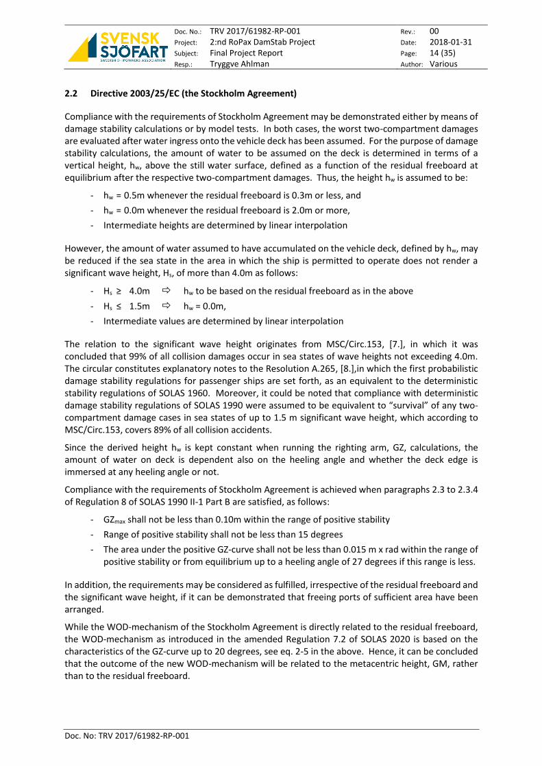
Compliance with the requirements of Stockholm Agreement may be demonstrated either by means of damage stability calculations or by model tests. In both cases, the worst two-compartment damages are evaluated after water ingress onto the vehicle deck has been assumed. For the purpose of damage stability calculations, the amount of water to be assumed on the deck is determined in terms of a vertical height, hw, above the still water surface, defined as a function of the residual freeboard at equilibrium after the respective two-compartment damages. Thus, the height hw is assumed to be:
- hw = 0.5m whenever the residual freeboard is 0.3m or less, and
- hw = 0.0m whenever the residual freeboard is 2.0m or more,
- Intermediate heights are determined by linear interpolation
However, the amount of water assumed to have accumulated on the vehicle deck, defined by hw, may be reduced if the sea state in the area in which the ship is permitted to operate does not render a significant wave height, Hs, of more than 4.0m as follows:
- Hs ≥ 4.0m hw to be based on the residual freeboard as in the above
- Hs ≤ 1.5m hw = 0.0m,
- Intermediate values are determined by linear interpolation
The relation to the significant wave height originates from MSC/Circ.153, [7.], in which it was concluded that 99% of all collision damages occur in sea states of wave heights not exceeding 4.0m. The circular constitutes explanatory notes to the Resolution A.265, [8.],in which the first probabilistic damage stability regulations for passenger ships are set forth, as an equivalent to the deterministic stability regulations of SOLAS 1960. Moreover, it could be noted that compliance with deterministic damage stability regulations of SOLAS 1990 were assumed to be equivalent to “survival” of any two-compartment damage cases in sea states of up to 1.5 m significant wave height, which according to MSC/Circ.153, covers 89% of all collision accidents.
Since the derived height hw is kept constant when running the righting arm, GZ, calculations, the amount of water on deck is dependent also on the heeling angle and whether the deck edge is immersed at any heeling angle or not.
Compliance with the requirements of Stockholm Agreement is achieved when paragraphs 2.3 to 2.3.4 of Regulation 8 of SOLAS 1990 II-1 Part B are satisfied, as follows:
- GZmax shall not be less than 0.10m within the range of positive stability
- Range of positive stability shall not be less than 15 degrees
- The area under the positive GZ-curve shall not be less than 0.015 m x rad within the range of positive stability or from equilibrium up to a heeling angle of 27 degrees if this range is less.
In addition, the requirements may be considered as fulfilled, irrespective of the residual freeboard and the significant wave height, if it can be demonstrated that freeing ports of sufficient area have been arranged.
While the WOD-mechanism of the Stockholm Agreement is directly related to the residual freeboard, the WOD-mechanism as introduced in the amended Regulation 7.2 of SOLAS 2020 is based on the characteristics of the GZ-curve up to 20 degrees, see eq. 2-5 in the above. Hence, it can be concluded that the outcome of the new WOD-mechanism will be related to the metacentric height, GM, rather than to the residual freeboard.

Doc. No.: TRV 2017/61982-RP-001 Project: 2:nd RoPax DamStab Project Subject: Final Project Report Resp.: Tryggve Ahlman
Rev.: 00 Date: 2018-01-31 Page: 15 (35) Author: Various
Doc. No: TRV 2017/61982-RP-001
Moreover, the operational aspects of the Stockholm Agreement in terms of the maximum significant wave height representing the geographical area in which the ship is allowed to operate, are not given any consideration in the adopted amendments of the SOLAS Convention.
Only a few ro-ro passenger ships currently in operation are designed and built to the SOLAS 2009 standards. Hence, the absolute majority of the ro-ro passenger ship fleet presently serving the European waters are built to SOLAS 1990 standards, and nowadays in compliance also with the requirements of the Stockholm Agreement. The experience from the application of SOLAS 2009 on to ro-ro passenger ships must hence be considered as limited. Nonetheless, since the damage assumptions and associated stability requirements of the directive are in fact based upon the deterministic approach as stipulated in SOLAS 1990, it seems likely to envisage that also future European ro-ro passenger ship designs must in principle be subdivided in accordance with the deterministic principles preceding the probabilistic approach.

Doc. No.: TRV 2017/61982-RP-001 Project: 2:nd RoPax DamStab Project Subject: Final Project Report Resp.: Tryggve Ahlman
Rev.: 00 Date: 2018-01-31 Page: 16 (35) Author: Various
Doc. No: TRV 2017/61982-RP-001
3 DAMAGE STABILITY ASSESSMENTS
3.1 Purpose of Assessments
The purpose of the subdivision and damage stability assessments as presented in this report is to evaluate the components of existing (SOLAS 2009 and Stockholm Agreement) and future (SOLAS 2020) stability standards in terms of:
1. Consequences of an increased required subdivision index R. It has been generally acknowledged that in most examined cases the requirements of the Stockholm Agreement, when applicable, governs the design, hence rendering some margin that would allow for an increase in Index R.
2. Influence of the introduction of SOLAS 2020 WOD-mechanism, as applicable for ro-ro passenger, in comparison with the existing Stockholm Agreement.
3. Influence of Risk Control Options, RCO:s, aiming at the mitigation of the effect of water ingress on to the vehicle deck, such as:
1) Arrangement of wide side casings on the vehicle deck
2) Arrangement of transverse barriers on vehicle deck.
For the purpose of the evaluation of different regulations, and moreover the effect of different Risk Control Options, RCO:s, aiming at the mitigation of the risk for and consequences of water ingress on the vehicle deck, the parameter minimum metacentric height, GMmin, as required for fulfilment of the respective requirements, has been used as the basis for comparisons.

Doc. No.: TRV 2017/61982-RP-001 Project: 2:nd RoPax DamStab Project Subject: Final Project Report Resp.: Tryggve Ahlman
Rev.: 00 Date: 2018-01-31 Page: 17 (35) Author: Various
Doc. No: TRV 2017/61982-RP-001
3.2 Selected Project Ship
For the purpose of the damage stability assessments of this project an existing ro-ro passenger ship, built in compliance with SOLAS 2009 + Stockholm Agreement, has been selected. It should be noted that, initially also a second existing ship, built in compliance with SOLAS 1990 + Stockholm Agreement, was selected for assessments. However, due to lack of detailed information, for example with regard to internal up-/down-flooding points which play a significant role in the outcome of the SOLAS 2009 and future SOLAS 2020 requirements, it was deemed that overall results in terms of an aggregated attained subdivision A, and consequently in terms of a minimum allowable GM would probably not be representative.
The Project Ship, the Main Particulars of which are presented in the below Figure 3-1, is considered to be a versatile pure ro-ro passenger ship for engagement in relatively short trades but with some overnight capacity in 130 passenger cabins.
Length Over All, LOA 212.00 m
Length btw. Perpendiculars, LPP: 194.80 m
Subdivision Length, LS 211.989 m
Breadth Moulded, BM: 26.70 m
Depth to Upper Deck, DU: 15.40 m
Depth to Main Deck, DM: 9.30 m
Draught, T: 6.30 m
Speed, V: 22.2 knots
Metacentric height, G’Mt 2.60 – 4.75 m
Deadweight @ 6.30 m 9 354 Tonnes
Lane Meters abt 4 050 m
Total Number of PoB 600 Crw+Pass
Lifeboat Capacity 2x 140p
Figure 3-1 Project Ship - SOLAS 2009 + SA Ro-Ro Passenger Ship – Profile and Main Particulars
The Project Ship is certified for unrestricted service, and hence a significant wave height of HS = 4.0m has been applied in the Stockholm Agreement calculations. In addition, according to the approved Stability Booklets, efficient cross-flooding arrangement are installed resulting in equalisation times well below 600 sec. Hence, cross-flooding has only been considered when Regulation 9 of SOLAS Chapter II-1 has been assessed.

Doc. No.: TRV 2017/61982-RP-001 Project: 2:nd RoPax DamStab Project Subject: Final Project Report Resp.: Tryggve Ahlman
Rev.: 00 Date: 2018-01-31 Page: 18 (35) Author: Various
Doc. No: TRV 2017/61982-RP-001
3.3 Validation of Hydrostatic Model and Stability Calculations
3.3.1 Validation of General Hydrostatic Data
The hydrostatic model constituting the basis for the damage stability calculations as outlined in this report has been validated against the hydrostatic data as presented in the approved intact and damage stability booklets. The results of the hydrostatic data validation, as presented in Table 3-1 and Table 3-2, fall well inside the tolerances as stipulated in the IMO Guidelines for the approval of Stability Instruments, MSC.1/Circ.1229, [9.].
HS1 from Approved Stability Booklet HS2 from Project Hydrostatic Model
Draught, TBL Δ LCB VCB KMT Δ LCB VCB KMT
[m] [tonnes] [m] [m] [m] [tonnes] [m] [m] [m]
4.485 13778.70 90.461 2.485 16.454 13772.13 90.489 2.485 16.441
4.985 15778.50 90.167 2.771 15.704 15770.51 90.197 2.771 15.686
5.485 17854.00 89.778 3.057 15.171 17845.15 89.807 3.058 15.155
5.788 19153.00 89.480 3.232 14.945 19143.47 89.508 3.233 14.942
5.985 20018.10 89.249 3.347 14.842 20008.16 89.276 3.347 14.844
6.285 21381.00 88.777 3.525 14.941 21371.15 88.800 3.525 14.941
6.300 21451.30 88.746 3.534 14.938 21441.46 88.770 3.534 14.942
Absolute difference = HS1 - HS2 Relative difference = (HS1 - HS2) / HS1
Draught, TBL δΔ δLCB δVCB δKMT δΔ δLCB δVCB δKMT
[m] [tonnes] [m] [m] [m] [%] [%] [%] [%]
4.485 6.57 -0.03 0.000 0.013 0.05% -0.03% 0.00% 0.08%
4.985 7.99 -0.03 0.000 0.018 0.05% -0.03% 0.00% 0.11%
5.485 8.85 -0.03 -0.001 0.016 0.05% -0.03% -0.03% 0.11%
5.788 9.53 -0.03 -0.001 0.003 0.05% -0.03% -0.03% 0.02%
5.985 9.94 -0.03 0.000 -0.002 0.05% -0.03% 0.00% -0.01%
6.285 9.85 -0.02 0.000 0.000 0.05% -0.03% 0.00% 0.00%
6.300 9.84 -0.02 0.000 -0.004 0.05% -0.03% 0.00% -0.03%
Table 3-1 Validation of Project Hull Model Hydrostatic Data
Approved Stability Booklet
Project Hydrostatic Model
Absolute Difference Relative Difference
Heeling Angle, Θ
GZ Area GZ Area δGZ δArea δGZ δArea
[deg.] [m] [m x rad] [m] [m x rad] [m] [m x rad] [%] [%]
0 0.000 0.000 0.000 0.000 0.000 0.0000 0.00% 0.00%
5 0.240 0.011 0.240 0.010 0.000 0.0010 0.00% 9.09%
10 0.456 0.041 0.456 0.041 0.000 0.0000 0.00% 0.00%
15 0.660 0.090 0.658 0.090 0.002 0.0000 0.30% 0.00%
20 0.844 0.156 0.837 0.155 0.007 0.0010 0.83% 0.64%
30 1.150 0.331 1.139 0.329 0.011 0.0020 0.96% 0.60%
40 1.234 0.545 1.217 0.539 0.017 0.0060 1.38% 1.10%
Table 3-2 Validation of Project Hull GZ-curve for one representative Loading Condition

Doc. No.: TRV 2017/61982-RP-001 Project: 2:nd RoPax DamStab Project Subject: Final Project Report Resp.: Tryggve Ahlman
Rev.: 00 Date: 2018-01-31 Page: 19 (35) Author: Various
Doc. No: TRV 2017/61982-RP-001
3.3.2 Calculation of Required Subdivision Index, R
In accordance with SOLAS Chapter II-1 Regulation 6, as stipulated in SOLAS 2009, the required subdivision index R for the Project Ship is calculated as follows:
𝑅𝑆𝑂𝐿𝐴𝑆2009 = 1 −5000
𝐿𝑆 + 2.5𝑁 + 15225= 0.7236
3.3.3 Recalculation of Attained Subdivision Index A at GMmin for compliance with Reg. 6
The attained subdivision index A, calculated in accordance with SOLAS 2009 Chapter II-1 Regulation 7, as reported in the approved Damage Stability Booklet for the selected ship is given for the aggregated minimum allowable metacentric height, GMmin, with some small additional margin. Hence, for the purpose of facilitating comparisons between SOLAS 2009, SOLAS 2020 and the requirements of Stockholm Agreement, the attained index A for the Project Ship has been recalculated for the GMmin as required for compliance with SOLAS 2009 Regulation 6, see Table 3-3. The recalculated attained index A(GMmin) hereby constitutes the basis for further comparisons.
As reported in Approved Stability Booklet Recalculated A for GMmin(Reg.6)
Load Line w-coeff
Draught TBL Trim GM A A/R GMmin AGMmin A/RGMmin
[-] [m] [m] [-] [-] [-] [-] [-] [-]
dL 0.20 5.019 -0.056 2.200 0.8892 1.23 1.604 0.8195 1.13
dP 0.40 5.788 0.000 2.050 0.8302 1.15 1.454 0.7509 1.04
dS 0.40 6.300 0.000 2.300 0.7464 1.03 1.704 0.6590 0.91
Overall Attained Subdivision Index A 0.8085 0.7279
Table 3-3 Recalculation of Attained Subdivision Index A for GMmin(Reg.6)
3.3.4 Validation of Stockholm Agreement Calculations
The Stockholm Agreement calculations show a slight deviation, between the information as reported in the approved Damage Stability Booklet and the results as derived for the Project Ship Hydrostatic Model, in terms of minimum allowable GM in particular for the summer load line draught ds, see Table 3-4 in the below.
Load Line
Draught TBL
Trim Governing
Damage Case Approved
GMmin Project GMmin
Diff. δGMmin
Diff. δGMmin
[m] [m] [-] [m] [m] [m] [%]
dL 5.019 -0.056 WODS4-5.1.0-1 1.664 1.710 0.046 2.76
dP 5.788 0.000 WODS4-5.1.0-2 1.510 1.550 0.040 2.65
dS 6.300 0.000 WODS13-14.1.0 2.014 2.150 0.136 6.75
Table 3-4 Validation of the Stockholm Agreement Calculations

Doc. No.: TRV 2017/61982-RP-001 Project: 2:nd RoPax DamStab Project Subject: Final Project Report Resp.: Tryggve Ahlman
Rev.: 00 Date: 2018-01-31 Page: 20 (35) Author: Various
Doc. No: TRV 2017/61982-RP-001
Since the approved Damage Stability Booklet does neither convey any information with regard to minimum freeboard following the respective damage cases nor the height of water, hw, to be considered on the vehicle deck, it has been somewhat difficult to identify the cause of the noted deviation. Nonetheless, in order to establish a consistent assessment, the GMmin-values as derived for the Project Ship Hydrostatic Model have been used as a basis for further comparisons.
3.3.5 Basis for Assessment - GMmin
For the purpose of establishing a basis for comparison of the assessment results, the following GMmin-values, see Table 3-5 and Figure 3-2, has been derived.
Load Line
Draught TBL
Trim over LS
Reg 7 GMmin
Reg 8.1 GMmin
Reg 8.2 GMmin
Reg 9 GMmin
SA GMmin
[m] [m] [m] [m] [m] [m] [m]
dL 5.019 -0.056 1.604 0.450 1.602 2.192 1.710
dP 5.788 0.000 1.454 0.437 1.441 1.995 1.550
dS 6.300 0.000 1.704 0.835 1.874 2.120 2.150
Table 3-5 Minimum Allowable GM-values – SOLAS 2009 + SA
Figure 3-2 Graphical representation of GMmin – SOLAS 2009 + SA
dL
dP
dS
0.00
0.20
0.40
0.60
0.80
1.00
1.20
1.40
1.60
1.80
2.00
2.20
2.40
5.00 5.10 5.20 5.30 5.40 5.50 5.60 5.70 5.80 5.90 6.00 6.10 6.20 6.30 6.40
Min
imu
m A
llow
able
GM
[m]
Draught [m]
SOLAS 2009 + SAGMmin
Reg. 9 SA Reg. 8.2 SOLAS 2009 Reg. 7 Reg. 8.1
Doc. No.: TRV 2017/61982-RP-001 Project: 2:nd RoPax DamStab Project Subject: Final Project Report Resp.: Tryggve Ahlman
Rev.: 00 Date: 2018-01-31 Page: 21 (35) Author: Various
Doc. No: TRV 2017/61982-RP-001
3.4 General Assessment of SOLAS Chapter II-1 Regulation 7 - Attained Subdivision Index A
3.4.1 Influence of Trim in the calculation of Attained Subdivision Index A
As stipulated in SOLAS II-1 Regulation 6, the ratio A/R as derived for any of the three load lines shall in no case be less than 0.9, see chapter 2.1.2 in the above. Moreover, in Regulation 7 it is implied that the calculation of index A for the summer load draught and the partial load draught at even keel, may be considered as valid whenever the operational trim does not exceed ±0.5% of LS, see chapter 2.1.3 in the above.
However, for the Project Ship, it could be noted that the A/R-ratio falls significantly below the required A/R ≥ 0.9 both for the summer load draught as well as for the partial load draught whenever an aft trim of 0.5% x LS = 0.005 x 211.989m = 1.060m is applied, see Table 3-6.
Load Line w-coeff
Draught TBL
Trim over LPP
SOLAS 2009 Reg 7 GMmin A A/R
[-] [m] [m] [-] [-] [-]
dL 0.20 5.019 -1.116 1.604 0.7686 1.0623
dP 0.40 5.788 -1.060 1.454 0.5481 0.757
dS 0.40 6.300 -1.060 1.704 0.6204 0.857
Overall Attained Subdivision Index A 0.6211
Table 3-6 Influence of Trim on the Attained Subdivision Index A
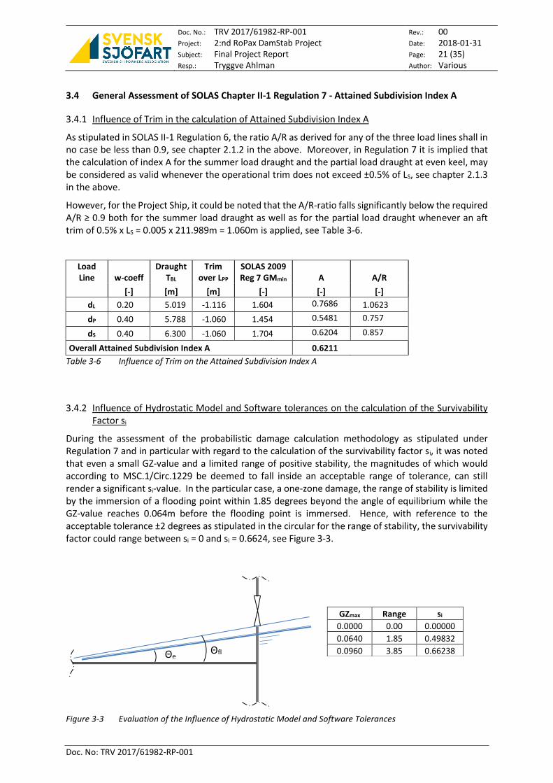
3.4.2 Influence of Hydrostatic Model and Software tolerances on the calculation of the Survivability Factor si
During the assessment of the probabilistic damage calculation methodology as stipulated under Regulation 7 and in particular with regard to the calculation of the survivability factor si, it was noted that even a small GZ-value and a limited range of positive stability, the magnitudes of which would according to MSC.1/Circ.1229 be deemed to fall inside an acceptable range of tolerance, can still render a significant si-value. In the particular case, a one-zone damage, the range of stability is limited by the immersion of a flooding point within 1.85 degrees beyond the angle of equilibrium while the GZ-value reaches 0.064m before the flooding point is immersed. Hence, with reference to the acceptable tolerance ±2 degrees as stipulated in the circular for the range of stability, the survivability factor could range between si = 0 and si = 0.6624, see Figure 3-3.
Figure 3-3 Evaluation of the Influence of Hydrostatic Model and Software Tolerances
GZmax Range si
0.0000 0.00 0.00000
0.0640 1.85 0.49832
0.0960 3.85 0.66238 Θe Θfl
d

Doc. No.: TRV 2017/61982-RP-001 Project: 2:nd RoPax DamStab Project Subject: Final Project Report Resp.: Tryggve Ahlman
Rev.: 00 Date: 2018-01-31 Page: 22 (35) Author: Various
Doc. No: TRV 2017/61982-RP-001
3.5 Assessment of SOLAS 2020 Chapter II-1 Regulation 6
In accordance with SOLAS Chapter II-1 Regulation 6, as stipulated in SOLAS 2020, the required subdivision index R for the Project Ship is calculated as follows:
𝑅𝑆𝑂𝐿𝐴𝑆2020 = 𝑁 7580 + 0.66923⁄ = 0.7484 for 400 ≤ N ≤ 1350
In comparison with the calculation of index R in accordance with SOLAS 2009 the absolute increase for the Project Ship amounts up to 0.7484 - 0.7263 = 0.0221 which corresponds to about 3% relative increase.
3.6 Assessment of SOLAS 2020 Chapter II-1 Regulation 7
3.6.1 Influence of the SOLAS 2020 Chapter II-1 Regulation 7.2 WOD-mechanism
In order to allow for a quantification of the influence of the WOD-mechanism, applicable to ro-ro passenger ships, as introduced in the adopted amendments to Regulation 7.2 in SOLAS 2020, the attained subdivision index A has been derived for the three respective load lines using the GMmin-values as derived for Regulation 7.2 in SOLAS 2009 as a basis. The results of this investigation are summarised in Table 3-7.
Load Line w-coeff
Draught TBL
Trim over LPP
SOLAS 2009 Reg 7 GMmin
SOLAS 2009 A
SOLAS 2020 A
Diff. ’09-‘20 δA
[-] [m] [m] [m] [-] [-] [-]
dL 0.20 5.019 -0.056 1.604 0.8195 0.8067 0.0128
dP 0.40 5.788 0.000 1.454 0.7509 0.7344 0.0165
dS 0.40 6.300 0.000 1.704 0.6590 0.6376 0.0214
Overall Attained Subdivision Index A 0.7279 0.7101 0.0178
Table 3-7 Influence of SOLAS 2020 WOD-mechanism
Based upon the above it is concluded that, for the Project Ship, the WOD-mechanism in SOLAS 2020 reduces the overall attained subdivision index A by 0.7279 – 0.7101 = 0.0178 which corresponds to a relative reduction of about 2.4%.
3.6.2 Assessment of the full Scope of SOLAS 2020 Chapter II-1 Regulation 7
When now applying the adopted amendments to Regulation 6 with regard to the raise in index R together with the WOD-mechanism to be applied for ro-ro passenger ships as introduced in the amendments to Regulation 7.2, the GMmin-values as presented in Table 3-8 can be derived.
Load Line w-coeff
Draught TBL
Trim over LPP
SOLAS 2020 Reg 7 GMmin A A/R
[-] [m] [m] [m] [-] [-]
dL 0.20 5.019 -0.056 1.754 0.8430 1.1264
dP 0.40 5.788 0.000 1.604 0.7654 1.0227
dS 0.40 6.300 0.000 1.854 0.6853 0.9157
Overall Attained Subdivision Index A 0.7489
Table 3-8 SOLAS 2020 - Attained Subdivision Index A Calculation for GMmin(Reg. 7)

Doc. No.: TRV 2017/61982-RP-001 Project: 2:nd RoPax DamStab Project Subject: Final Project Report Resp.: Tryggve Ahlman
Rev.: 00 Date: 2018-01-31 Page: 23 (35) Author: Various
Doc. No: TRV 2017/61982-RP-001
A comparison between the GMmin-values for compliance with Regulation 7 as stipulated in SOLAS 2009 and SOLAS 2020 respectively reveals that, for the Project Ship, the required increase in GM corresponds to about 0.150m. However, it should be noted that, for reasons of consistency, a constant shift in metacentric height has been applied for all three respective load lines. It could probably be possible to better optimise the GMmin-values for respective load lines, but the influence of such an optimisation is deemed to be less significant since the A/R-ration for the summer load line, ds, the draught at which the freeboard is minimum and hence a change in GM would render the highest “leverage” on index A, is already close to the minimum 0.9. Nonetheless, even though Regulation 7 of SOLAS 2020 could possibly be considered as equivalent to Stockholm Agreement at light load line, dL, and at partial load line, dP, equivalence seems to be far from achievable at the summer load line ds.
Load Line
Draught TBL
Trim over LPP
SOLAS 2009 Reg 7 GMmin
SOLAS 2020 Reg 7 GMmin
Diff. ’20-‘09 GMmin
SA GMmin
Diff. ‘20-SA GMmin
[m] [m] [m] [m] [m] [m] [m]
dL 5.019 -0.056 1.604 1.754 0.150 1.710 0.044
dP 5.788 0.000 1.454 1.604 0.150 1.550 0.054
dS 6.300 0.000 1.704 1.854 0.150 2.150 -0.296
Table 3-9 Comparison of Min. Allowable GM – SOLAS 2009 Reg. 7, SOLAS 2020 Reg. 7 and SA
Figure 3-4 Graphical representation of GMmin - SOLAS 2009 Reg. 7, SOLAS 2020 Reg. 7 and SA
However, for the Project Ship, the deterministic stability requirements of Regulation 9, pertinent to prescriptive bottom damages, governs by far, the overall minimum allowable metacentric height, GMmin, in particular for the light and partial load lines, see Figure 3-4.
dL
dP
dS
0.00
0.20
0.40
0.60
0.80
1.00
1.20
1.40
1.60
1.80
2.00
2.20
2.40
5.00 5.10 5.20 5.30 5.40 5.50 5.60 5.70 5.80 5.90 6.00 6.10 6.20 6.30 6.40
Min
imu
m A
llow
able
GM
[m]
Draught [m]
SOLAS 2020 + SAGMmin
Reg. 9 SA SOLAS 2020 Reg. 7 Reg. 8.2 SOLAS 2009 Reg. 7 Reg. 8.1

Doc. No.: TRV 2017/61982-RP-001 Project: 2:nd RoPax DamStab Project Subject: Final Project Report Resp.: Tryggve Ahlman
Rev.: 00 Date: 2018-01-31 Page: 24 (35) Author: Various
Doc. No: TRV 2017/61982-RP-001
4 ASSESSMENT OF RISK CONTROL OPTIONS, RCO:S, INTENDED TO MITIGATE THE CONSEQUENCES OF WATER ON DECK
4.1 RCO1 – Transverse Barriers on Vehicle Deck
Following the entry into force of the Stockholm Agreement, the arrangement of transverse barriers on the vehicle deck has proven to be an effective means to mitigate the consequences of water ingress onto the ro-ro deck. Hence, the effect of such barriers on the outcome of damage stability calculations has been assessed in terms of influence on the minimum allowable metacentric height, GMmin, for compliance both with Stockholm Agreement and with SOLAS 2020.
For the Project Ship, one transverse barrier has been arranged just abaft of the aft boundaries of the worst Stockholm Agreement two-compartment damage case.
Figure 4-1 RCO1 - Arrangement of one Transverse Barrier on Vehicle Deck
4.1.1 Influence on the fulfilment of the requirements of Stockholm Agreement
As could be expected, for the Project Ship, the arrangement of one barrier on vehicle deck will significantly reduce the GMmin, as required for compliance with the requirements of the Stockholm Agreement, for the summer load line draught when the initial intact freeboard and consequently also the residual freeboard after damage are limited. Accordingly, the effect of barriers is more or less negligible whenever an adequate freeboard is provided, see Table 4-1.
Load Line
Draught TBL
Trim Governing
Damage Case Project GMmin
Barrier GMmin
Diff. δGMmin
[m] [m] [-] [m] [m] [m]
dL 5.019 -0.056 WODS4-5.1.0-1 1.710 1.706 -0.004
dP 5.788 0.000 WODS4-5.1.0-2 1.550 1.550 0.000
dS 6.300 0.000 WODS13-14.1.0 2.150 1.960 -0.190
Table 4-1 Influence of one Barrier on the fulfilment of Stockholm Agreement Requirements

Doc. No.: TRV 2017/61982-RP-001 Project: 2:nd RoPax DamStab Project Subject: Final Project Report Resp.: Tryggve Ahlman
Rev.: 00 Date: 2018-01-31 Page: 25 (35) Author: Various
Doc. No: TRV 2017/61982-RP-001
4.1.2 Influence on the fulfilment of the requirements of SOLAS 2020
For reasons of consistency the metacentric height has been reduced by a constant value for all three load line draughts until the required subdivision index R is met. The effect of the barrier at summer load line, expressed in terms of a reduction of the minimum GM as required for compliance with the requirements of Regulation 6 of SOLAS 2020, is not equally recognised compared to the Stockholm Agreement calculation methodology, see Table 4-2.
Load Line w-coeff
Draught TBL
Trim over LPP
Project GMmin
Barrier GMmin
SOLAS 2020 A A/R
Diff. δGMmin
[-] [m] [m] [m] [m] [-] [-] [m]
dL 0.20 5.019 -0.056 1.754 1.640 0.8304 1.1095 -0.114
dP 0.40 5.788 0.000 1.604 1.490 0.7714 1.0307 -0.114
dS 0.40 6.300 0.000 1.854 1.740 0.6877 0.9189 -0.114
Overall Attained Subdivision Index A 0.7497
Table 4-2 Influence of one Barrier on the fulfilment of SOLAS 2020 Reg. 7 Requirements
Even though some optimization of the minimum allowable GM-values for the respective load lines could possibly be applied, the A/R-ratio for the summer load line, ds, does not give room for any significant reduction of GMmin. In addition, the WOD-mechanism as introduced in the adopted Regulation 7.2 of SOLAS 2020 allows for a significantly lesser GMmin at the summer load line draught than the GMmin as required for compliance with Stockholm Agreement.
4.2 RCO2 - Wide Side Casings
Another RCO, that would effectively mitigate the risk for capsize when water ingress on the vehicle deck has occurred following a collision damage, is the arrangement of wide watertight side casings. Based upon time domain simulations, as reported in the below chapter 5, it is indicated that a side casing width of 8% of the investigated ship’s beam would extend the time to capsize, for the worst two-compartment and three-compartment damage cases, beyond 180 minutes in a sea state signified by a significant wave height of HS = 4.0m. Hence, the effect of wide side casings on the outcome of damage stability calculations has been assessed in terms of influence on the GMmin-values for compliance both with Stockholm Agreement and with SOLAS 2020.
The selected width of each side casing is 2.95m, which for the Project Ship corresponds 10.9% of the ships beam. The loss in payload is 208 lane meters (one lane per side) and corresponds to about 5% of the total ro-ro capacity.
Figure 4-2 RCO2 - Arrangement of Wide Side Casings

Doc. No.: TRV 2017/61982-RP-001 Project: 2:nd RoPax DamStab Project Subject: Final Project Report Resp.: Tryggve Ahlman
Rev.: 00 Date: 2018-01-31 Page: 26 (35) Author: Various
Doc. No: TRV 2017/61982-RP-001
4.2.1 Influence on the fulfilment of the requirements of Stockholm Agreement
In accordance with the above chapter 4.1 related to the RCO – Barriers on Vehicle Deck, for the Project Ship, the arrangement of wide side casings on vehicle deck will significantly reduce the GMmin, as required for compliance with the requirements of the Stockholm Agreement, for the summer load line draught when the initial intact freeboard and consequently also the residual freeboard after damage are limited. Accordingly, the effect of the wide side casings is more or less negligible whenever an adequate freeboard is provided, see Table 4-3.
Load Line
Draught TBL
Trim Governing
Damage Case Project GMmin
W. Side Casings GMmin
Diff. δGMmin
[m] [m] [-] [m] [m] [m]
dL 5.019 -0.056 WODS4-5.1.0-1 1.710 1.706 -0.004
dP 5.788 0.000 WODS4-5.1.0-2 1.550 1.470 -0.080
dS 6.300 0.000 WODS13-14.1.0 2.150 1.865 -0.285
Table 4-3 Influence of Wide Side Casings on the fulfilment of Stockholm Agreement Requirements
4.2.2 Influence on the fulfilment of the requirements of SOLAS 2020
In analogy with the above chapters, for reasons of consistency the metacentric height has been reduced by a constant value for all three load line draughts until the required subdivision index R is met. Yet again it is concluded that the effect of the wide side casings at summer load line, expressed in terms of a reduction of the minimum GM as required for compliance with the requirements of Regulation 6 of SOLAS 2020, is not equally recognised when compared to the Stockholm Agreement calculation methodology, see Table 4-4.
Load Line w-coeff
Draught TBL
Trim over LPP
Project GMmin
W. Side Casings GMmin
SOLAS 2020 A A/R
Diff. δGMmin
[-] [m] [m] [m] [m] [-] [-] [m]
dL 0.20 5.019 -0.056 1.754 1.650 0.8320 1.1117 -0.104
dP 0.40 5.788 0.000 1.604 1.500 0.7697 1.0284 -0.104
dS 0.40 6.300 0.000 1.854 1.750 0.6878 0.9190 -0.104
Overall Attained Subdivision Index A 0.7494
Table 4-4 Influence of one Barrier on the fulfilment of SOLAS 2020 Reg. 7 Requirements
Even though some optimization of the minimum allowable GM-values for the respective load lines could possibly be applied, the A/R-ratio for the summer load line, ds, does not give room for any significant reduction of GMmin. In addition, it is again concluded that the WOD-mechanism as introduced in the adopted Regulation 7.2 of SOLAS 2020 allows for a significantly lesser GMmin at the summer load line draught than the corresponding GMmin as required for compliance with Stockholm Agreement.
Doc. No.: TRV 2017/61982-RP-001 Project: 2:nd RoPax DamStab Project Subject: Final Project Report Resp.: Tryggve Ahlman
Rev.: 00 Date: 2018-01-31 Page: 27 (35) Author: Various
Doc. No: TRV 2017/61982-RP-001
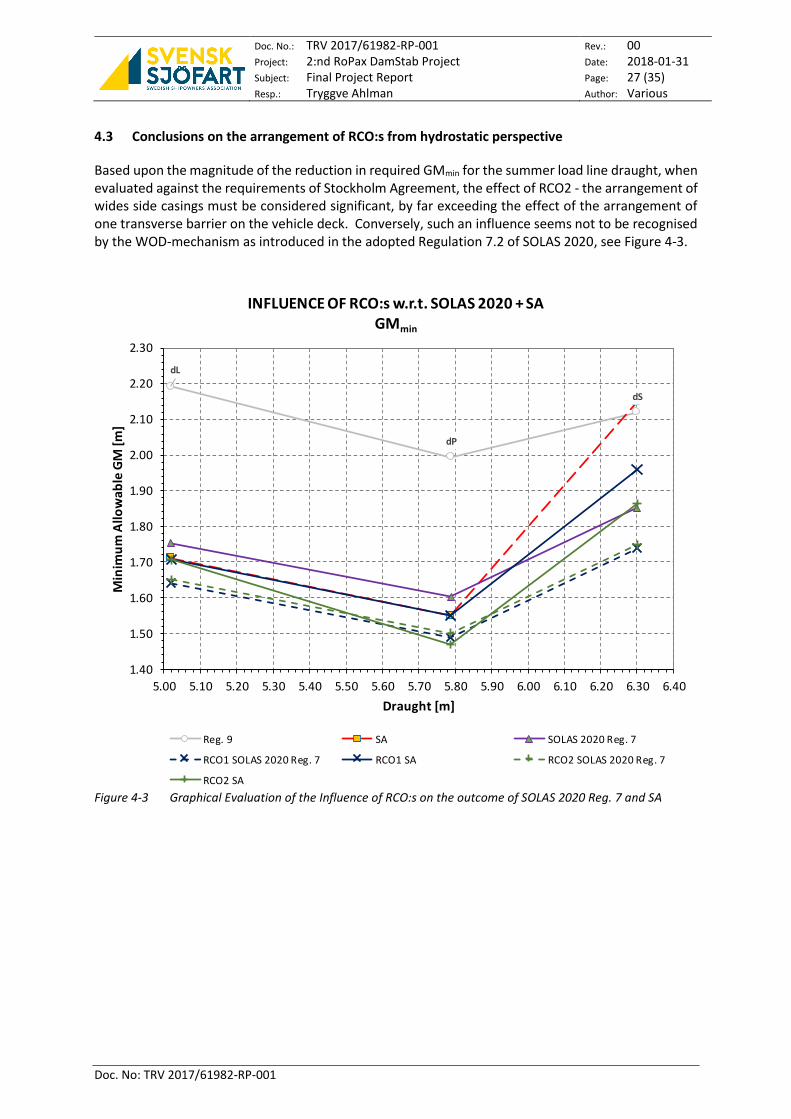
4.3 Conclusions on the arrangement of RCO:s from hydrostatic perspective
Based upon the magnitude of the reduction in required GMmin for the summer load line draught, when evaluated against the requirements of Stockholm Agreement, the effect of RCO2 - the arrangement of wides side casings must be considered significant, by far exceeding the effect of the arrangement of one transverse barrier on the vehicle deck. Conversely, such an influence seems not to be recognised by the WOD-mechanism as introduced in the adopted Regulation 7.2 of SOLAS 2020, see Figure 4-3.
Figure 4-3 Graphical Evaluation of the Influence of RCO:s on the outcome of SOLAS 2020 Reg. 7 and SA
dL
dP
dS
1.40
1.50
1.60
1.70
1.80
1.90
2.00
2.10
2.20
2.30
5.00 5.10 5.20 5.30 5.40 5.50 5.60 5.70 5.80 5.90 6.00 6.10 6.20 6.30 6.40
Min
imu
m A
llow
able
GM
[m]
Draught [m]
INFLUENCE OF RCO:s w.r.t. SOLAS 2020 + SAGMmin
Reg. 9 SA SOLAS 2020 Reg. 7
RCO1 SOLAS 2020 Reg. 7 RCO1 SA RCO2 SOLAS 2020 Reg. 7
RCO2 SA

Doc. No.: TRV 2017/61982-RP-001 Project: 2:nd RoPax DamStab Project Subject: Final Project Report Resp.: Tryggve Ahlman
Rev.: 00 Date: 2018-01-31 Page: 28 (35) Author: Various
Doc. No: TRV 2017/61982-RP-001
5 IN-DEPTH ASSESSMENT OF RCO2 – WIDE SIDE CASINGS
5.1 Introduction
A study has been made to assess the impact of watertight side casings as a risk control option for damaged RoPax ships. The assessment is made through damage stability calculations in accordance with SOLAS 2009 and SOLAS 2020 as well as numerical time domain simulations with the SIMCAP tool, described in e.g. Schreuder et al. (2012) [10.] or Schreuder (2014) [11.]. The example ship and the set of design variations and damage scenarios used in the study are described below together with the results and discussion.
The study shows that WT side casings can be an effective RCO and that the actual safety can be substantially increased beyond what is assessed through regulations.
5.1 Background
SOLAS 2020 highlights the vulnerability of damage scenarios where the WT integrity of any Roro spaces are breached through a more conservative definition of the s factor for these damage cases. This strengthens the incentive to find effective RCOs for damaged Ropax ships.
From a damage stability perspective, side casings with transverse WT subdivision outside of a large un-divided roro space will enhance the stability characteristics in a scenario where the WT integrity of the roro space is breached and where a large part of the side casing is still intact. This is expected to influence the hydrostatic calculations required in SOLAS 2009 and 2020 as well as for the physically more realistic simulations where the presence of waves and the mechanisms of the flooding process are modelled. The present study aims to investigate this influence through a parameter study with different side casing configurations of an example ship.
The example ship was presented in Ahlman et al. (2015), [1.], and Figure 5-1 shows the two-compartment damage case of the ship.
Figure 5-1 Two compartment damage case of the example ship with the damage opening in red.
In Ahlman et al. (2015) [1.] the ship had its original configuration with one center casing close to the CL of the ship; this casing has virtually no effect of the transverse stability of the ship in a damage scenario. This configuration has been tested through model experiments (Rask 2010) and was simulated for a range of significant wave heights with 20 wave realisations for each wave height to account for the random nature of the seas and with beam seas onto the damaged side. The ship was flooded to the static damage equilibrium at the start of the simulation.

Doc. No.: TRV 2017/61982-RP-001 Project: 2:nd RoPax DamStab Project Subject: Final Project Report Resp.: Tryggve Ahlman
Rev.: 00 Date: 2018-01-31 Page: 29 (35) Author: Various
Doc. No: TRV 2017/61982-RP-001
Note that the margin line will not be submerged in this two-compartment damage case. If the waves are high enough water will however reach the vehicle deck on which it could be accumulated until the stability is lost and the ship capsizes. The results are shown in Figure 5-2 in which the time to capsize of all experiments and simulations of the example ship are collected. The appearance of the plot in the figure is typical for ships with large vehicle decks with a transition zone, or capsize band, through which the capsize rate changes from no capsize to 100% capsize (or strictly, from low to high probability, depending on the number of wave realizations) as indicated in the plot. Note that the tests and simulations were stopped after 30 minutes and that the markers at 1800 seconds in Figure 5-2 represent survival (no capsize) cases.
Figure 5-2 Experimental and numerical data of the time to capsize. No side casing. Two compartment damage.
In the following section the scenarios of the present study are described. The simulations are similar to the Ahlman et al. (2015) study [1.] outlined above.
5.2 Set-up of the study
The design changes applied to the ship consist of the fitting of side casings of different widths instead of the original center casing. The casings have the same transverse subdivision as the ship and are placed on the intersections of the vehicle deck and two vertical planes with a fixed transverse distance to the maximum beam of the ship on the SB and PS respectively, see Figure 5-3. Three different casing configurations are used with a width of 0, 1, 1.5 and 2 m corresponding to casing width to beam percentages of about 0, 4, 6 and 8 % respectively.
The fitting of side casings is assumed to contribute significantly to both the survival factor s and the survival time or time to capsize, Tcap. Hence a more severe three-compartment damage, see Figure 5-4, is tested in addition to the two-compartment damage in Figure 5-1 and the maximum simulation time is set to three hours instead of the 30 minutes used in the previous study. In the simulations the three-compartment damage was obtained by allowing for progressive flooding through two WT-doors whilst the damage opening through the hull was the same for the two damage cases. This opening corresponds to a SOLAS standard damage opening with a transverse penetration of B/5, thus allowing for flooding of the vehicle deck for all casing configurations such that the more strict SOLAS 2020 s factor formulation will be triggered.
0 200 400 600 800 1000 1200 1400 1600 18000
0.5
1
1.5
2
2.5
3
3.5
4
Tcap
[s]
Hs [
m]
20 simulations/model tests for each wave height
(no model tests above Hs=3m)
SIMCAP simulation
SSPA experiment
No capsize
Capsize

Doc. No.: TRV 2017/61982-RP-001 Project: 2:nd RoPax DamStab Project Subject: Final Project Report Resp.: Tryggve Ahlman
Rev.: 00 Date: 2018-01-31 Page: 30 (35) Author: Various
Doc. No: TRV 2017/61982-RP-001
Figure 5-3 Side casings of 2 m width. 1.5 and 1.0 m casings are outlined in grey. The widths correspond to about 8%, 6% and 4% of the beam respectively.
At the start of each simulation the ship is floating at the damage equilibrium of the two-compartment damage and for the three-compartment cases the WT-doors are assumed to be opened at this instant.
All sea states in the simulations are represented by a Jonswap spectra with γ=3.3 and 𝑇𝑝 = 4 ∙ √𝐻𝑠.
Significant wave heights in the simulations are 3, 3.5 and 4 meters. 10 realizations are simulated for each wave height.
Figure 5-4 Three-compartment damage case of the example ship with the damage openings in red. In this
case two WT doors (red dots) are assumed to be open in addition to the damage opening in the two-compartment damage of Figure 5-1, effectively resulting in a three compartment damage.
5.3 Results
Figure 5-5 shows the s factor versus width of side casings for the two- and three-compartment damages, as calculated with SOLAS 2009 and SOLAS 2020 respectively. s=1 is reached for the two wider side casings with the two-compartment damage assessed through SOLAS 2009.
Figure 5-6 show the critical wave heights, Hscrit, corresponding to the s values. Hscrit=4s4 and can be interpreted as the significant wave height where there is a 50% probability that the ship will capsize within 30 minutes, see further Ahlman et al. (2015) [1.].
In Table 5-1 all results of the hydrostatic calculations are presented.
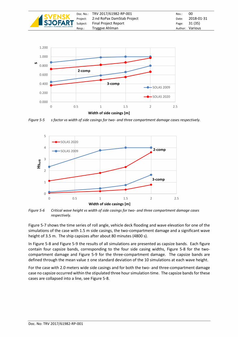
Doc. No.: TRV 2017/61982-RP-001 Project: 2:nd RoPax DamStab Project Subject: Final Project Report Resp.: Tryggve Ahlman
Rev.: 00 Date: 2018-01-31 Page: 31 (35) Author: Various
Doc. No: TRV 2017/61982-RP-001
Figure 5-5 s factor vs width of side casings for two- and three compartment damage cases respectively.
Figure 5-6 Critical wave height vs width of side casings for two- and three compartment damage cases
respectively.
Figure 5-7 shows the time series of roll angle, vehicle deck flooding and wave elevation for one of the simulations of the case with 1.5 m side casings, the two-compartment damage and a significant wave height of 3.5 m. The ship capsizes after about 80 minutes (4800 s).
In Figure 5-8 and Figure 5-9 the results of all simulations are presented as capsize bands. Each figure contain four capsize bands, corresponding to the four side casing widths, Figure 5-8 for the two-compartment damage and Figure 5-9 for the three-compartment damage. The capsize bands are defined through the mean value ± one standard deviation of the 10 simulations at each wave height.
For the case with 2.0 meters wide side casings and for both the two- and three-compartment damage case no capsize occurred within the stipulated three hour simulation time. The capsize bands for these cases are collapsed into a line, see Figure 5-8.
0.000
0.200
0.400
0.600
0.800
1.000
1.200
0 0.5 1 1.5 2 2.5
SOLAS 2009
SOLAS 2020
0
1
2
3
4
5
0 0.5 1 1.5 2 2.5
SOLAS 2020
SOLAS 2009
Width of side casings [m]
2-comp
3-comp
s
Width of side casings [m]
Hs c
rit
2-comp
3-comp

Doc. No.: TRV 2017/61982-RP-001 Project: 2:nd RoPax DamStab Project Subject: Final Project Report Resp.: Tryggve Ahlman
Rev.: 00 Date: 2018-01-31 Page: 32 (35) Author: Various
Doc. No: TRV 2017/61982-RP-001
Figure 5-7 Time series of one of the 10 simulations with a side casing of 1.5 m, two compartment damage case and a significant wave height of 3.5 m. The result of this simulation, Tcap close to 80 minutes, is shown as a black dot in Figure 5-8
Figure 5-8 Capsize bands of the two-compartment damage cases. The black dot corresponds to the simulation in Figure 5-7. No capsizes occurred within 180 minutes for the 1.5m side casing configuration at the wave height of 3m. The configuration with 2m wide side casings showed no capsizes for any of the simulated wave heights, shown as a vertical line at Tcap=180 minutes.
In Figure 5-10 the simulation results are presented in a plot with the mean value of time to capsize versus the width of the side casings.
0 500 1000 1500 2000 2500 3000 3500 4000 4500 5000-40
-20
0
20
40Time simulation (4,8,-1.8,8,0)
time [s]
response [
m],
[degre
es],
[m3/1
00]
roll
car deck
wave
0
0.5
1
1.5
2
2.5
3
3.5
4
4.5
0 20 40 60 80 100 120 140 160 180 200
.
Tcap [minutes]
Hs
[m]
No sidecasing 1m sidecasing 1.5m sidecasing 2m sidecasing (no capsizes)
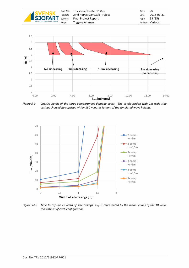
Doc. No.: TRV 2017/61982-RP-001 Project: 2:nd RoPax DamStab Project Subject: Final Project Report Resp.: Tryggve Ahlman
Rev.: 00 Date: 2018-01-31 Page: 33 (35) Author: Various
Doc. No: TRV 2017/61982-RP-001
Figure 5-9 Capsize bands of the three-compartment damage cases. The configuration with 2m wide side casings showed no capsizes within 180 minutes for any of the simulated wave heights.
Figure 5-10 Time to capsize vs width of side casings. Tcap is represented by the mean values of the 10 wave realizations of each configuration.
0
0.5
1
1.5
2
2.5
3
3.5
4
4.5
0.00 2.00 4.00 6.00 8.00 10.00 12.00 14.00
0
10
20
30
40
50
60
70
0 0.5 1 1.5 2
2-compHs=3m
2-compHs=3,5m
2-compHs=4m
3-compHs=3m
3-compHs=3,5m
3-compHs=4m
Tcap [minutes]
Hs
[m]
No sidecasing 1m sidecasing 1.5m sidecasing 2m sidecasing (no capsizes)
T cap
[m
inu
tes]
Width of side casings [m]

Doc. No.: TRV 2017/61982-RP-001 Project: 2:nd RoPax DamStab Project Subject: Final Project Report Resp.: Tryggve Ahlman
Rev.: 00 Date: 2018-01-31 Page: 34 (35) Author: Various
Doc. No: TRV 2017/61982-RP-001
dam/casing
heel@
eq
heel@
GZ0 range
heel@
max GZ
max
GZ
s SOLAS
2009
Hcrit SOLAS
2009
s SOLAS
2020
Hcrit SOLAS
2020
2comp 0m 1.90 12.21 10.31 7.50 0.109 0.875 2.34 0.728 1.12379
2comp 1m 1.90 15.50 13.60 9.30 0.133 0.985 3.77 0.820 1.8088
2comp 1,5m 1.90 17.80 15.90 10.30 0.146 1.000 4.00 0.873 2.3214
2comp 2m 1.90 22.85 20.95 11.80 0.172 1.000 4.00 0.974 3.6034
3comp 0m 2.03 5.70 3.67 3.52 0.020 0.442 0.15 0.368 0.0734
3comp 1m 2.03 8.44 6.41 5.03 0.035 0.585 0.47 0.487 0.22435
3comp 1,5m 2.03 10.15 8.12 6.25 0.045 0.660 0.76 0.550 0.3654
3comp 2m 2.03 13.51 11.48 7.83 0.069 0.801 1.65 0.667 0.79212
Table 5-1 Results of the hydrostatic calculations
5.4 Discussion/conclusions
A study has been done where the side casing width of an example ship have been systematically varied in order to assess the impact of water tight side casings as a risk control option for damaged RoPax ships. A two- and a three-compartment damage have been investigated through damage stability calculations in accordance with SOLAS 2009 and SOLAS 2020 as well as time domain numerical simulations.
In Figure 5-5 the impact of the difference between the SOLAS 2009 and SOLAS 2020 formulation of the survival factor s, can be seen. It also shows the trend of increasing s with increasing side casing width, also apparent in Figure 5-6, where the critical wave height versus side casing width is plotted. In the figures it can also be seen that the two compartment SOLAS 2009 case reaches the limits of s=1 and Hscrit=4m for the 1.5 and 2m side casings.
Figure 5-8 and Figure 5-9 also show a trend of increased survivability with increased side casing width. It is also clear that this trend continues well beyond what is assessed through the regulatory calculations i.e. survival times beyond three hours for all the 2m side casing cases.
Due to the limited number of simulated wave heights the critical wave heights are not established through the simulations. However, for all the 2m side casing cases, with the exception of the two-compartment case assessed through SOLAS 2009 which is indecisive due to maximum critical wave height, both SOLAS 2009 and SOLAS 2020 underestimates the critical wave height compared to the simulations. A similar comparison can be made between the calculated critical wave heights that are within the range of the simulations, namely the SOLAS 2009 cases of 1m and 1.5m side casings with Hscrit=3.77m and 4.0m respectively. The capsize bands of corresponding simulations are both below 30 minutes and thus the calculations overestimates the critical wave height compared to the simulations. These facts indicate that the regulations underestimate the strength of the trend of increasing survivability with increased side casing width.
The aim of the study has not been to investigate any commercial aspect of the side casing RCO. The side casings in the study is however not particularly wide and they would be utilised for e.g. staircases, elevators and technical equipment and the cargo space lost should be minor.
In conclusion the study shows that WT-side casings can be an effective RCO and that the actual safety can be substantially increased beyond what is assessed through regulations.

Doc. No.: TRV 2017/61982-RP-001 Project: 2:nd RoPax DamStab Project Subject: Final Project Report Resp.: Tryggve Ahlman
Rev.: 00 Date: 2018-01-31 Page: 35 (35) Author: Various
Doc. No: TRV 2017/61982-RP-001
6 REFERENCES
[1.] Ahlman T, et al., 2015, “Damage Stability Project for: RoRo Passenger Ships – Final Report”
[2.] IMO Resolution MSC.216(82), (8 December 2006), Amendments to the International Convention for the Safety of Life at Sea, 1974, as amended
[3.] European Maritime Safety Agency, 2015, “Combined assessment of cost-effectiveness of previous parts, FSA compilation and recommendations for decision making”, EMSA /OP/10/2013, Report No. 2015-0404, Rev.1 Doc. No. 18KJ9LI-60
[4.] IMO, The International Life-Saving Appliances (LSA) Code, 2017 Edition, ISBN 978-92-801-1654-0
[5.] IMO Resolution MSC.266(84), (2008), Code of Safety for Special Purpose Ships, 2008
[6.] Directive 2009/45/EC of the European Parliament and of the Council of 6 April 2009, On safety rules and standards for passenger ships
[7.] IMO Circular MSC.1/Circ.153, (28 Nov 1973), Regulations on Subdivision and Damage Stability of Passenger Ships as equivalent to Part B of Chapter II of the International Convention for the Safety of Life at Sea, 1960 (Resolution A.265) – Explanatory notes to the Regulations
[8.] IMO Resolution A.265, (20 November 1973), Regulations on subdivision and stability of passenger ships as an equivalent to part B of chapter II of the International Convention for the Safety of Life at Sea, 1960
[9.] IMO Circular MSC.1/Circ.1229, (11 Jan 2007), Guidelines for the Approval of Stability Intruments
[10.] Schreuder, M., Hogström, P., Ringsberg, J., Johnson, E., Janson, C-E. (2012), A Method for Assessment of the Survival Time of a Ship Damaged by Collision, Transactions - Society of Naval Architects and Marine Engineers, 119(1), 603-619.
[11.] Schreuder, M. (2014), Development, Implementation, Validation and Applications of a Method for Simulation of Damaged and Intact Ships in Waves. PhD Thesis, Chalmers University of Technology, ISBN: 978-91-7385-972-1, Göteborg, Sweden
~- ~- ~- ~- ~- ~- ~- ~- ~- ~- ~- ~- ~- ~-~ // ~- ~- ~- ~- ~- ~- ~- ~- ~- ~- ~- ~- ~- ~-~


![Deltamarin Roro References[1]](https://img.pdfslide.us/doc/110x75/577cda651a28ab9e78a58f5c/deltamarin-roro-references1.jpg)