Embed Size (px)
DESCRIPTION
Nanomaterials_FC_1
Citation preview
Nanomaterials for Fuel Cells
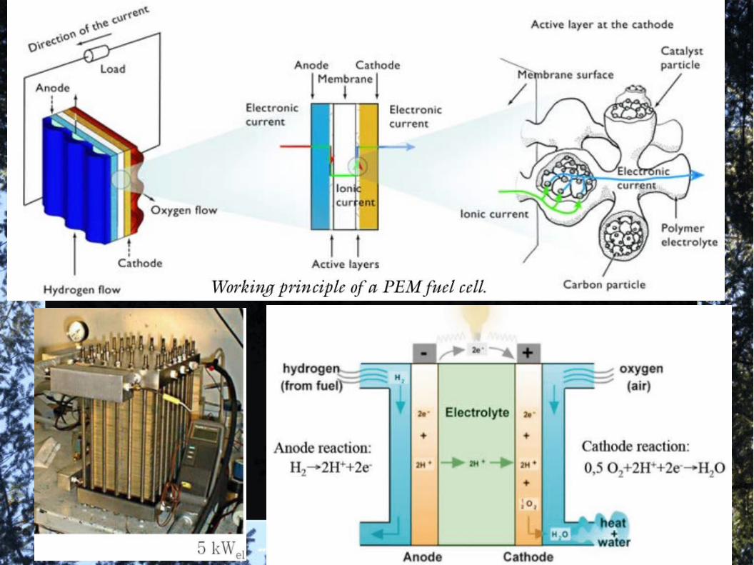
1)The importance of Fuel Cells and their Simulation.
2)The major Drawback for large-scale production. Carbon nanomaterials as metal-free catalysts (to replace Pt).
3)CNFs vs CNTs. Importance of large Active Area.
4)Other limitations.
1)The importance of Fuel Cells and their Simulation.
● The rapid increase in the global energy consumption and the environmental impact of traditional energy resources pose serious challenges to human health, energy security, and environmental protection.
● One promising solution, providing clean and sustainable power, is fuel cells.
● High energy conversion efficiency (typically, 40–60% or up to 85% efficiency if waste heat is captured for use) and high energy density, virtually no pollution, and potential large-scale applications.
● Fuel cells may have their greatest environmental impact in motor vehicles. In most automotive engines, gasoline is converted into mechanical energy through heat produced during combustion. The efficacy of this process is limited by the efficiency formula for the Carnot cycle, which describes the thermomechanical operation that takes place in a gasoline engine.

● Efficiency is fixed for a fixed T (~20% for an automobile).
● To bypass limitations of Carnot Cycle:
Fuel cell: U(chem.)---> U(elect.); Motor: U(elect.)--->U(mech)
● Efficiency increases to almost 90% (theo), 50% (exp).
● Consequently, carbondioxide emissions are lower, and the lower operating temperatures of fuel cells all but eliminate the production of nitrogen oxides (NOx) and sulfuric oxides (SOx).
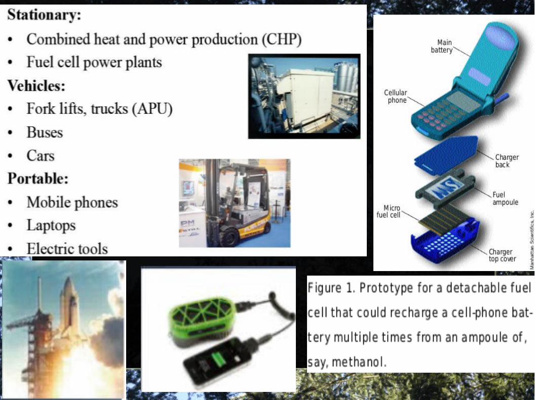
● The electronics industry is pursuing miniature fuel cells. Motorola has demonstrated a cellular telephone powered by a fuel cell whose operating time with one fuel cartridge is five times longer than that of a conventional battery with one recharge. Other likely applications include power supplies in laptop computers and portable video, audio, and entertainment equipment.
Fuel cells also provide an uninterrupted power supply because there is no self-dis charge, as occurs with batteries, an advantage that minimizes maintenance and maximizes the system’s reliability. In addition, fuel cells have a higher energy density and therefore a higher power capacity per unit of weight.
● Technology development is an important weapon at this stage, and small companies with technical skills in fuel-cell processes have become important partners to the large electronic and automotive companies.
● In this rapidly developing and highly competitive market, the time from idea to prototype has shrunk. Therefore, tools for developing virtual prototypes have become exceptionally important.
● Optimizing a fuel cell’s performance in combination with its auxiliary equipment and operation of the electric motor requires a lot of mathematical puzzling. A combination of modeling and experimentation has reduced the cost and accelerated the pace of building and understanding prototype systems.
● Modeling provides valuable insights into the electro-chemistry of the fuel cell and the processes that take place in the heart of the fuel-cell system (the electrodes and electrolyte in the fuel-cell stack).
● These processes are described at the microlevel: single catalyst agglomerates; a unit cell consisting of an anode, a cathode, and the electrolyte between them; and as reactor models of the fuel processor in fuel cells for cars.
●
●
●
●
●
●
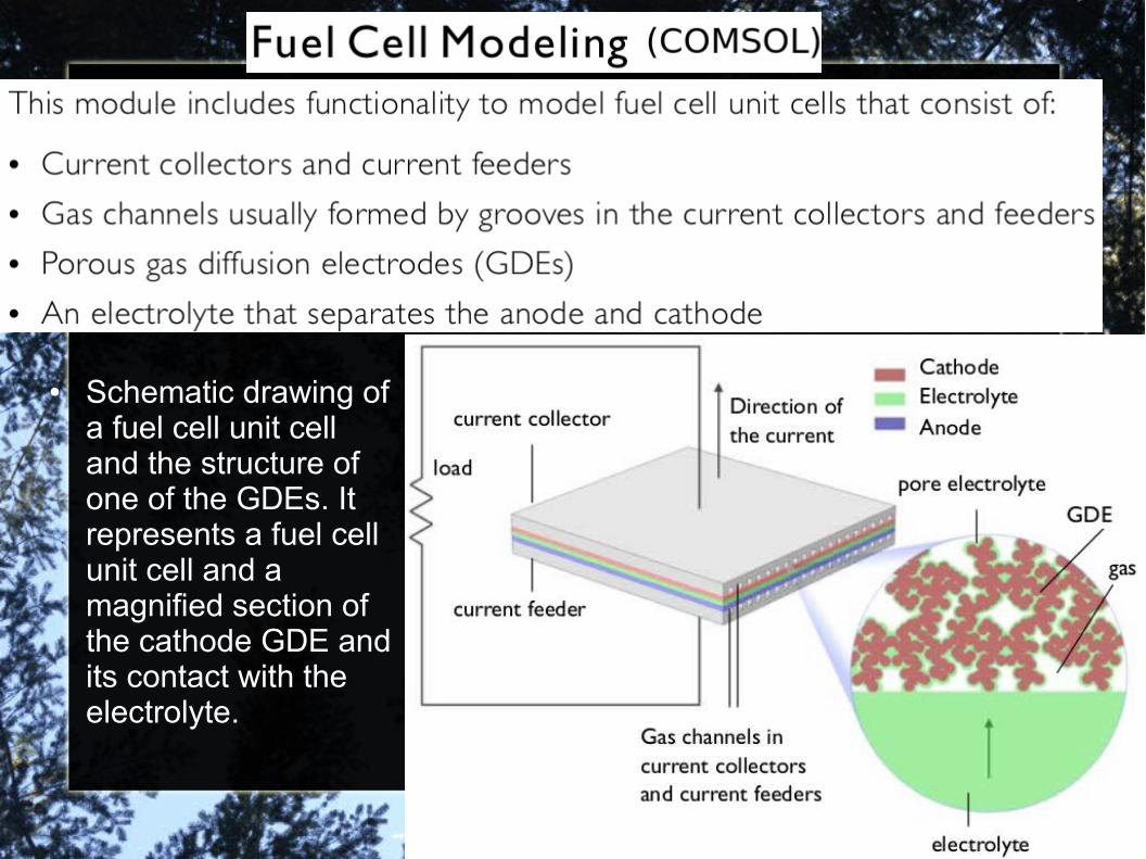
● Schematic drawing of a fuel cell unit cell and the structure of one of the GDEs. It represents a fuel cell unit cell and a magnified section of the cathode GDE and its contact with the electrolyte.
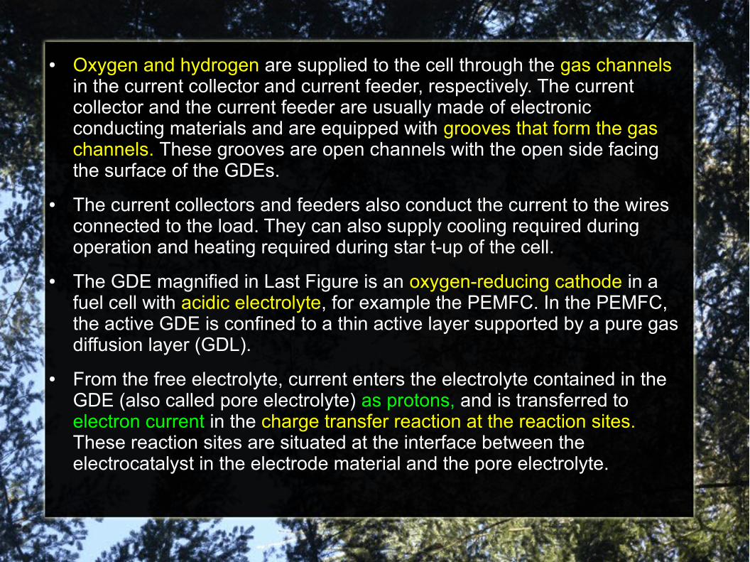
● Oxygen and hydrogen are supplied to the cell through the gas channels in the current collector and current feeder, respectively. The current collector and the current feeder are usually made of electronic conducting materials and are equipped with grooves that form the gas channels. These grooves are open channels with the open side facing the surface of the GDEs.
● The current collectors and feeders also conduct the current to the wires connected to the load. They can also supply cooling required during operation and heating required during star t-up of the cell.
● The GDE magnified in Last Figure is an oxygen-reducing cathode in a fuel cell with acidic electrolyte, for example the PEMFC. In the PEMFC, the active GDE is confined to a thin active layer supported by a pure gas diffusion layer (GDL).
● From the free electrolyte, current enters the electrolyte contained in the GDE (also called pore electrolyte) as protons, and is transferred to electron current in the charge transfer reaction at the reaction sites. These reaction sites are situated at the interface between the electrocatalyst in the electrode material and the pore electrolyte.
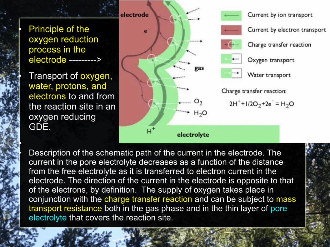
● Principle of the oxygen reduction process in the electrode --------->
● Transport of oxygen, water, protons, and electrons to and from the reaction site in an oxygen reducing GDE.
●
● Description of the schematic path of the current in the electrode. The current in the pore electrolyte decreases as a function of the distance from the free electrolyte as it is transferred to electron current in the electrode. The direction of the current in the electrode is opposite to that of the electrons, by definition. The supply of oxygen takes place in conjunction with the charge transfer reaction and can be subject to mass transport resistance both in the gas phase and in the thin layer of pore electrolyte that covers the reaction site.
●
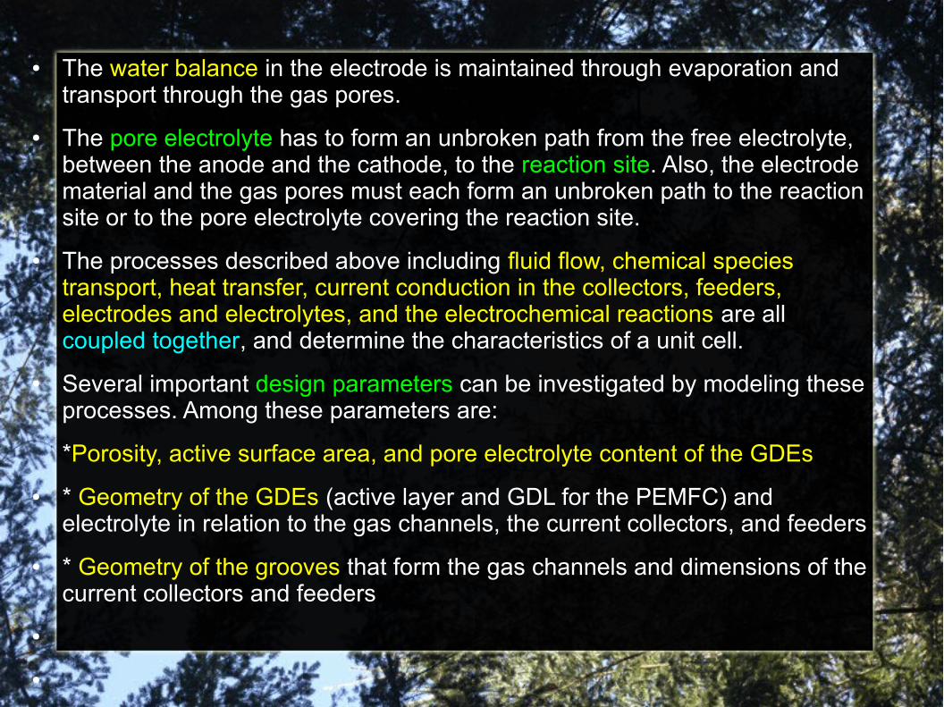
● The water balance in the electrode is maintained through evaporation and transport through the gas pores.
● The pore electrolyte has to form an unbroken path from the free electrolyte, between the anode and the cathode, to the reaction site. Also, the electrode material and the gas pores must each form an unbroken path to the reaction site or to the pore electrolyte covering the reaction site.
● The processes described above including fluid flow, chemical species transport, heat transfer, current conduction in the collectors, feeders, electrodes and electrolytes, and the electrochemical reactions are all coupled together, and determine the characteristics of a unit cell.
● Several important design parameters can be investigated by modeling these processes. Among these parameters are:
*Porosity, active surface area, and pore electrolyte content of the GDEs
● * Geometry of the GDEs (active layer and GDL for the PEMFC) and electrolyte in relation to the gas channels, the current collectors, and feeders
● * Geometry of the grooves that form the gas channels and dimensions of the current collectors and feeders
●
●
Different simulations can be performed
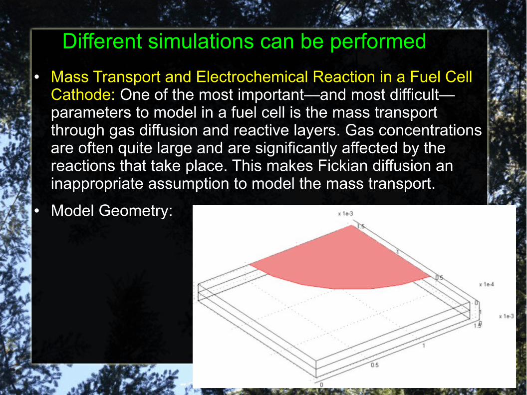
● Mass Transport and Electrochemical Reaction in a Fuel Cell Cathode: One of the most important—and most difficult—parameters to model in a fuel cell is the mass transport through gas diffusion and reactive layers. Gas concentrations are often quite large and are significantly affected by the reactions that take place. This makes Fickian diffusion an inappropriate assumption to model the mass transport.
● Model Geometry:

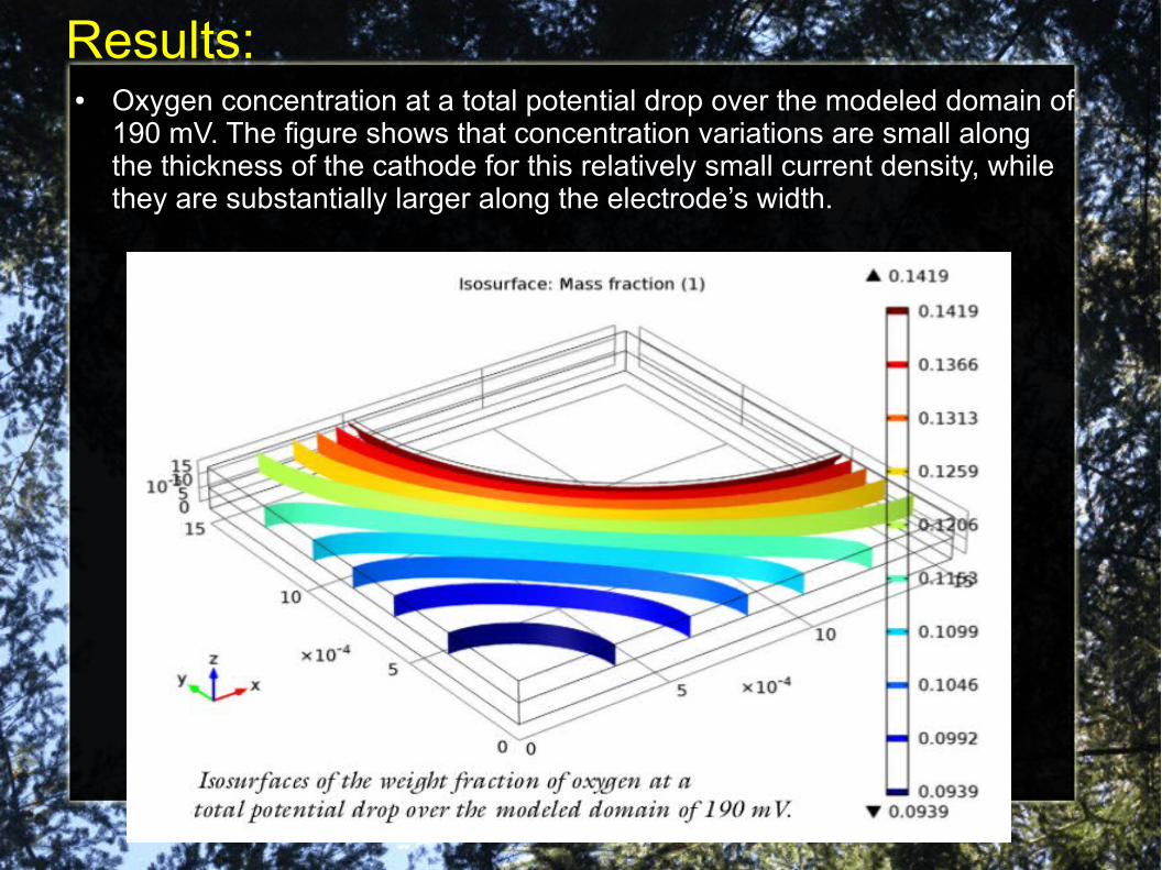
● Oxygen concentration at a total potential drop over the modeled domain of 190 mV. The figure shows that concentration variations are small along the thickness of the cathode for this relatively small current density, while they are substantially larger along the electrode’s width.
Results:
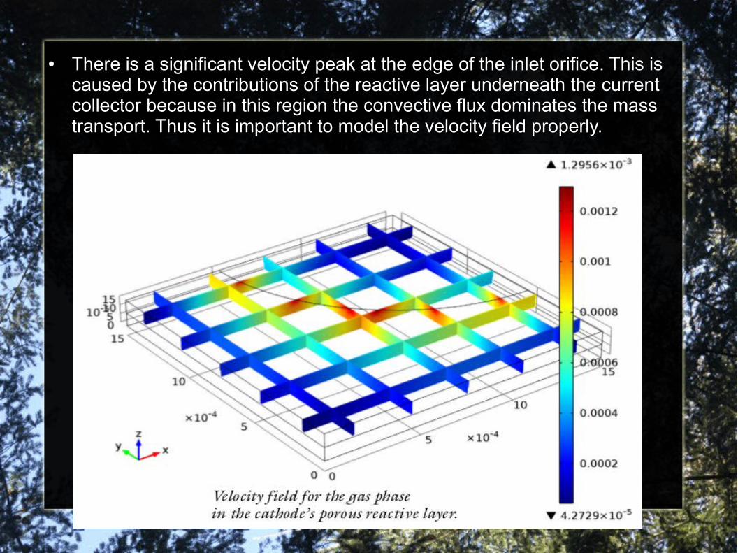
● There is a significant velocity peak at the edge of the inlet orifice. This is caused by the contributions of the reactive layer underneath the current collector because in this region the convective flux dominates the mass transport. Thus it is important to model the velocity field properly.
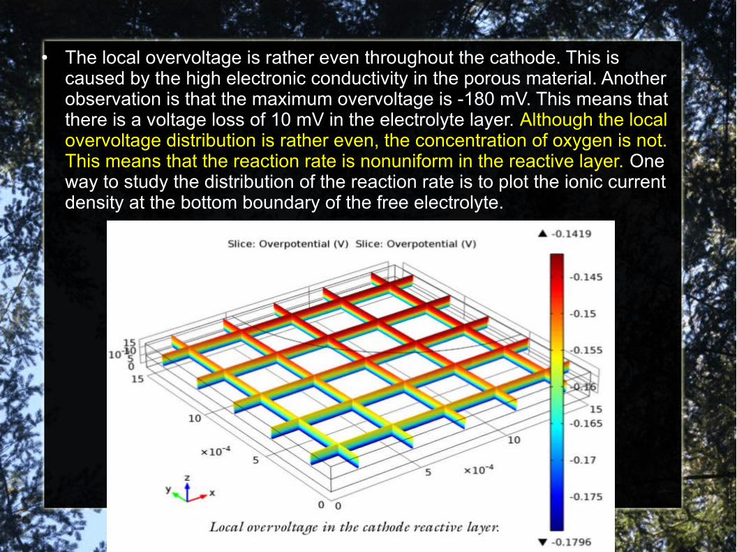
● The local overvoltage is rather even throughout the cathode. This is caused by the high electronic conductivity in the porous material. Another observation is that the maximum overvoltage is -180 mV. This means that there is a voltage loss of 10 mV in the electrolyte layer. Although the local overvoltage distribution is rather even, the concentration of oxygen is not. This means that the reaction rate is nonuniform in the reactive layer. One way to study the distribution of the reaction rate is to plot the ionic current density at the bottom boundary of the free electrolyte.
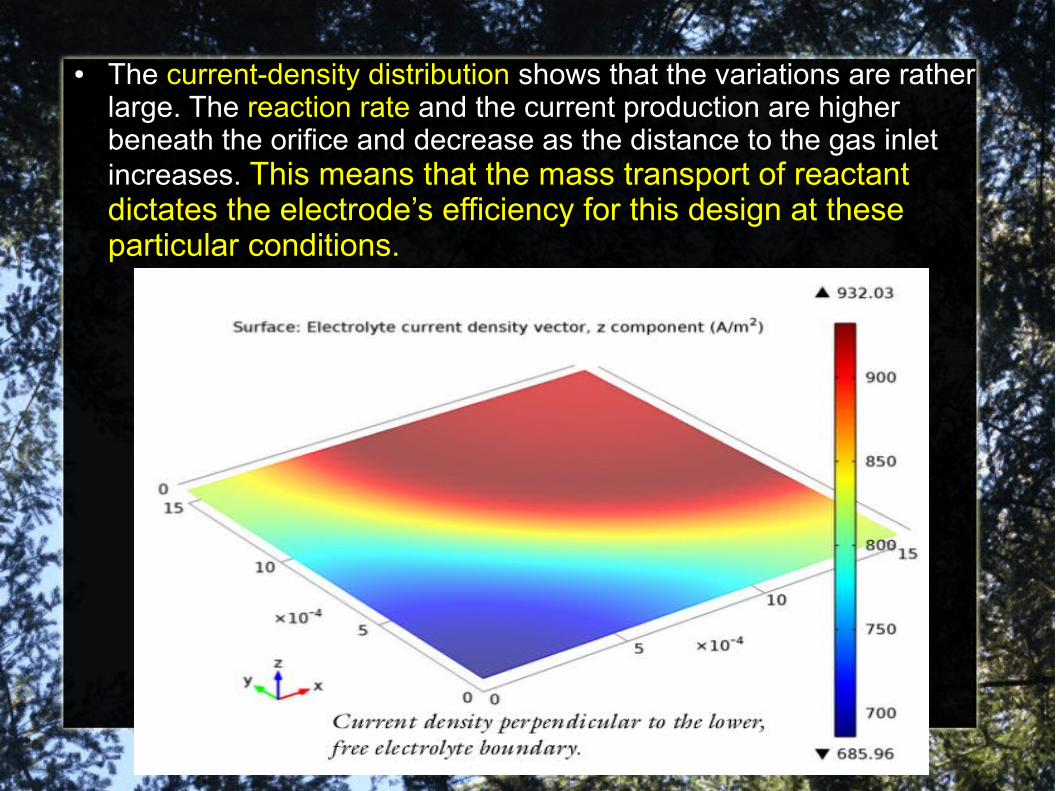
● The current-density distribution shows that the variations are rather large. The reaction rate and the current production are higher beneath the orifice and decrease as the distance to the gas inlet increases. This means that the mass transport of reactant dictates the electrode’s efficiency for this design at these particular conditions.
Another example....
Species Transport in the Gas Diffusion layers of a PEM
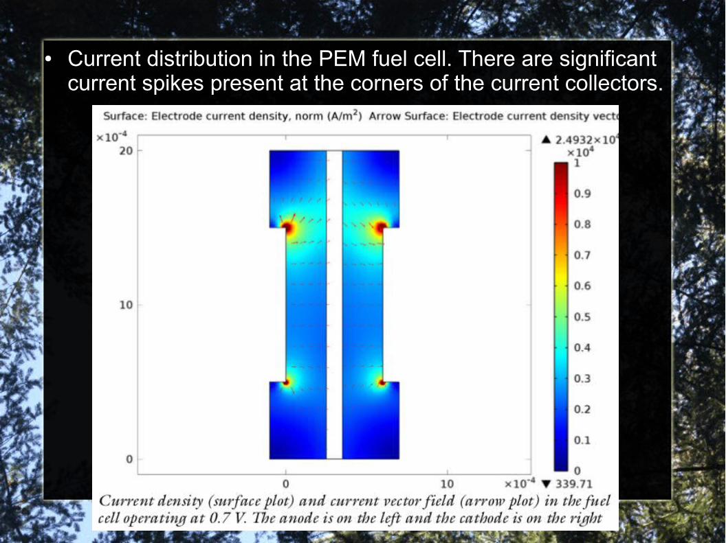
● Current distribution in the PEM fuel cell. There are significant current spikes present at the corners of the current collectors.

● To further analyze the cell’s behavior, plot the current density at the active layer as a function of cell height (y). The current density is uneven with the highest density in the cell’s upper region. This means that the oxygen-reduction reaction rate in the cathode determines the current-density distribution. The maximum current density arises close to the air inlet.
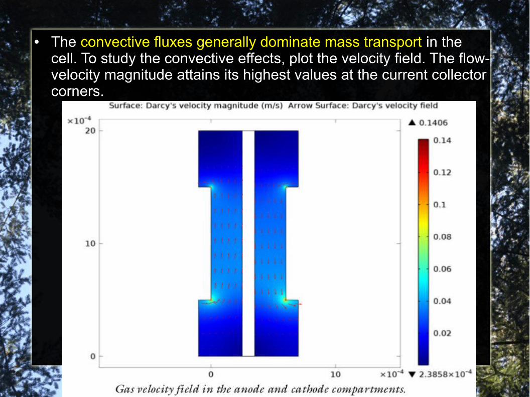
● The convective fluxes generally dominate mass transport in the cell. To study the convective effects, plot the velocity field. The flow-velocity magnitude attains its highest values at the current collector corners.
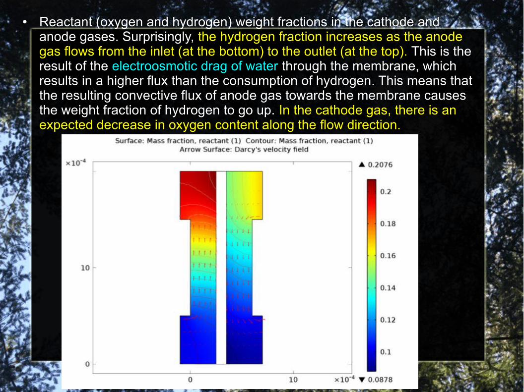
● Reactant (oxygen and hydrogen) weight fractions in the cathode and anode gases. Surprisingly, the hydrogen fraction increases as the anode gas flows from the inlet (at the bottom) to the outlet (at the top). This is the result of the electroosmotic drag of water through the membrane, which results in a higher flux than the consumption of hydrogen. This means that the resulting convective flux of anode gas towards the membrane causes the weight fraction of hydrogen to go up. In the cathode gas, there is an expected decrease in oxygen content along the flow direction.
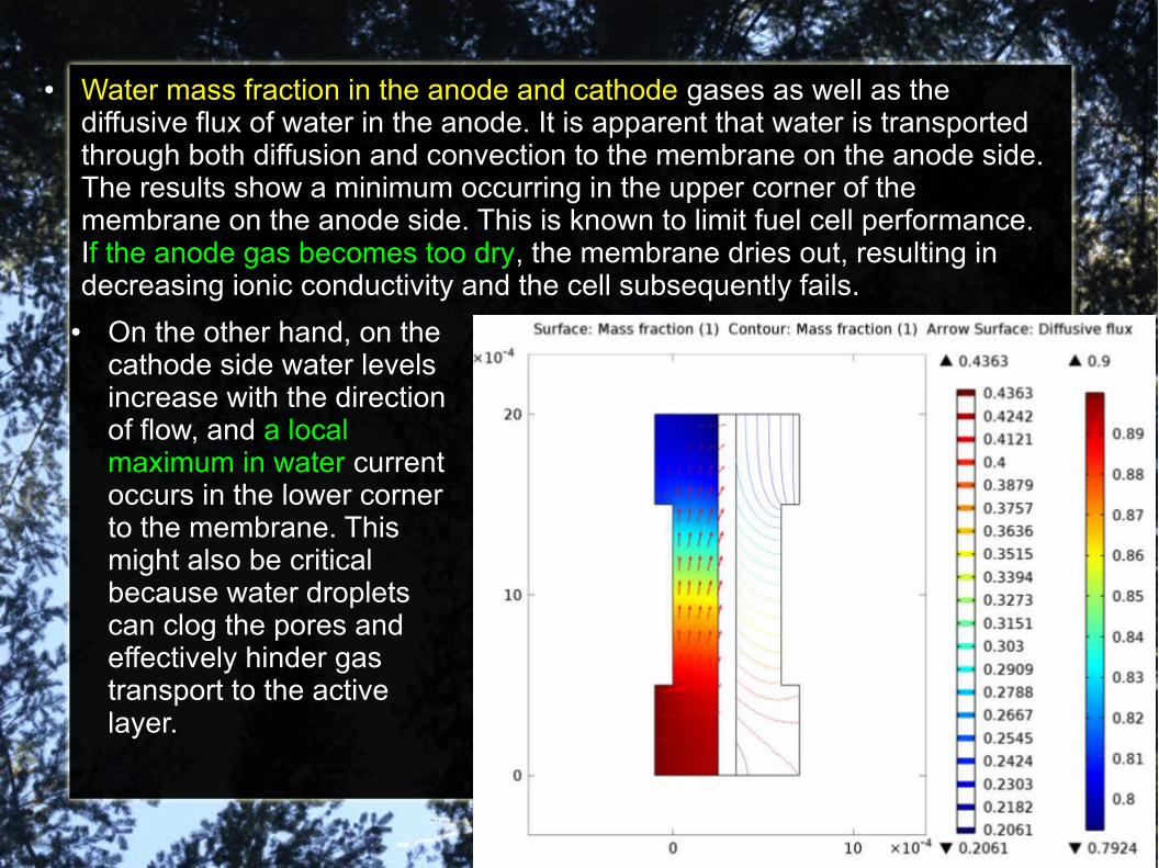
● Water mass fraction in the anode and cathode gases as well as the diffusive flux of water in the anode. It is apparent that water is transported through both diffusion and convection to the membrane on the anode side. The results show a minimum occurring in the upper corner of the membrane on the anode side. This is known to limit fuel cell performance. If the anode gas becomes too dry, the membrane dries out, resulting in decreasing ionic conductivity and the cell subsequently fails.
● On the other hand, on the cathode side water levels increase with the direction of flow, and a local maximum in water current occurs in the lower corner to the membrane. This might also be critical because water droplets can clog the pores and effectively hinder gas transport to the active layer.
Let's return to materials for Fuel-Cells
● In order to perform simulations we have to specify physical parameters that are going to enter the PDE that govern the physical processes described before.
● The PEM fuel cell electrodes are of the gas diffusion type. They consist of a supporting carbon structure with gas-filled pores (denoted gas backing) and a porous active layer that also contains the polymer electrolyte. The electrochemical reactions take place in the active layer, which contains a platinum catalyst. The gas diffusion electrodes are designed to maximize the specific area available for the reaction, maximize the distribution of reactant (that is, achieve a low gas-transport resistance), and minimize the resistance for the proton transport to and from the active sites at the electrodes.
● So I decided to find out more information about Nanomaterials for Fuel Cells........
2)The major Drawback for commercial applications. Carbon nanomaterials as metal-free catalysts (to replace Pt).
● While the very facile H2 oxidation kinetics greatly reduces the amount of catalyst (e.g., platinum) at the anode, the slow oxygen reduction reaction (ORR) on the cathode is a key step to limit the energy conversion efficiency of a fuel cell and requires a substantial amount of platinum catalyst (representing at least a quarter of the fuel cell cost).
● Although platinum nanoparticles have long been regarded as the best catalyst for the ORR, the Pt-based electrode suffers multiple drawbacks, including its time-dependent drift, methanol crossover, and CO deactivation.
● This, together with the high cost of platinum and its scarcity, has made these catalysts the primary barrier to mass market fuel cells for commercial applications. Thus, the large-scale practical application of fuel cells has not been realized, though alkaline fuel cells with platinum as an ORR electrocatalyst were developed for the Apollo lunar mission in the 1960s.
● Even though the amount of platinum needed for the desired catalytic effect could be reduced using Pt alloys, most non-noble metal catalysts still remain too low in efficiency when compared to Pt or too expensive as commercial mass production would still require large amounts of platinum. The large-scale practical application of fuel cells will be difficult to realize if the expensive platinum-based electrocatalysts for ORR cannot be replaced by other efficient, low cost, and stable electrodes.
● Along with the intensive research efforts in reducing or replacing Pt-based electrode in fuel cells, a new class of carbon nanomaterials has been discovered, which, as alternative ORR catalysts, could dramatically reduce the cost and increase the efficiency of fuel cells.
● Their research has found that vertically-aligned nitrogen-doped carbon nanotube (VA-NCNT) arrays can act as a metal-free electrode to catalyze an ORR process free from CO ‘‘poisoning’’ with a 3-times higher electrocatalytic activity, much smaller crossover effect, and better long-term operational stability than that of the commercial platinum-based electrode (C2-20, 20% platinum on Vulcan XC-72R; E-TEK) in alkaline fuel cells.
●
●
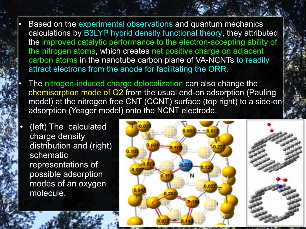
● Based on the experimental observations and quantum mechanics calculations by B3LYP hybrid density functional theory, they attributed the improved catalytic performance to the electron-accepting ability of the nitrogen atoms, which creates net positive charge on adjacent carbon atoms in the nanotube carbon plane of VA-NCNTs to readily attract electrons from the anode for facilitating the ORR.
● The nitrogen-induced charge delocalization can also change the chemisorption mode of O2 from the usual end-on adsorption (Pauling model) at the nitrogen free CNT (CCNT) surface (top right) to a side-on adsorption (Yeager model) onto the NCNT electrode.
● (left) The calculated charge density distribution and (right) schematic representations of possible adsorption modes of an oxygen molecule.
● The N-induced charge-transfer from adjacent carbon atoms could lower the ORR potential while the parallel diatomic adsorption could effectively weaken the O–O bonding, facilitating ORR at the VA-NCNT electrode. Uncovering this new ORR mechanism in the nitrogen-doped carbon nanotube electrode is significant as that the same principle could be applied to the development of various other metal-free efficient ORR catalysts for fuel cell applications.
● Although it is still a challenge to determine the exact locations of nitrogen atoms in the carbon nanotube structures and chemical nature of the catalytic sites, recent research activities carried out in many laboratories, including our own one, have not only confirmed the above findings but also further proved that the doping-induced charge transfer has large impact on the design/development of new metal-free catalytic materials for fuel cell and many other applications.
● For instance, Yang et al. have recently extended the doping atoms to include Boron with a lower electronegativity than that of carbon.
● These authors found that the doping-induced charge redistribution, regardless whether the dopants have a higher (as N) or lower (as B) electronegativity than that of carbon, could create charged sites (C + or B + ) favorable for O2 adsorption to facilitate the ORR process.
● This work suggests further exploration of the metal-free electrocatalysts based on carbon nanotubes doped by atoms (other than N and B) with electronegativities different from that of carbon atom.
● By extension, they have successfully prepared vertically-aligned BCN (VA-BCN) nanotubes containing both nitrogen and boron heteroatoms. Due to a synergetic effect arising from the co-doping of carbon nanotubes with boron and nitrogen, the resultant VA-BCN nanotubes were demonstrated to show a higher electrocatalytic activity for ORR in alkaline medium than VA-CNTs doped with either boron or nitrogen only.
●
● The observed superior ORR performance with a good methanol and CO tolerance and excellent durability for the VA-BCN nanotube electrode than the commercial Pt/C electrode opens up avenues for the development of novel efficient metal-free ORR catalysts by co-doping carbon nanotubes with more than one heteroatom of electro-negativities different from that of carbon atom.
● As a building block for carbon nanotubes, graphene is an alternative candidate for potential uses as the metal-free ORR catalyst. Indeed, N-doped graphene (N-graphene) films produced by chemical vapor deposition (CVD) in the presence of ammonia have recently been demonstrated to show a superb ORR performance similar to that of VA-NCNTs with the same nitrogen content in alkaline medium.
● The ease with which graphene materials and their N-doped derivatives can be produced by various low-cost, large-scale methods, ranging from the CVD to solution exfoliation of graphite, suggests considerable room for cost effective preparation of metal-free efficient graphene-based catalysts for oxygen reduction.
●
● In addition, Liu et al. have reported the ORR electrocatalytic performance better than platinum for nitrogen-doped ordered mesoporous graphitic arrays (NOMGAs) prepared by a metal-free nanocasting technology using a nitrogen-containing aromatic dyestuff, N,N0 -bis(2,6-diisopropyphenyl)-3,4,9,10-perylenetetracarboxylic diimide (PDI), as the carbon precursor. Owing to the metal-free preparation procedure, the reported electrocatalytic activity can be attributed exclusively to the incorporation of nitrogen in PDI-NOMGAs.
● In a somewhat related, but independent study, Liu et al. have demonstrated phosphorus-doped graphite layers with high electrocatalytic activity for ORR in an alkaline medium.
● Metal-freeN-doped MWCNTs or ordered mesoporous carbons (OMCS) have also been produced through carbonization of a MWCNT-supported polyaniline (PANI) coating or via NH3 activation.
● These metal-free N-doped nanocarbons have also been demonstrated to exhibit high ORR activities even in acidic electrolytes. Good ORR activities in the acidic media have also been observed for NCNTs produced by both metal catalyzed and metal-free nanotube growth processes.
● However, the catalytic performance of these reported N-doped carbon nanomaterials in acidic medium still needs to be further improved to meet the requirement for practical applications.
● In addition to the intramolecular charge-transfer that impart ORR electrocatalytic activities to heteroatom-doped carbon nanotubes, graphene and graphite described above, they have recently demonstrated that certain polyelectrolyte (e.g., poly(diallyldimethylammonium chloride)) adsorbed pure carbon CNTs or graphene, either in an aligned or nonaligned form, could also act as metal-free electrocatalysts for ORR through the intermolecular charge-transfer from the all-carbon CNTs or graphene to the adsorbed PDDA.
● It is notable that the PDDA adsorbed vertically aligned CNT electrode possesses remarkable electrocatalytic properties for ORR; similar to that of commercially available Pt/C electrode. These results clearly indicate that the important role of intermolecular charge-transfer to ORR can be applied to carbon nanomaterials in general for the development of various other metal-free efficient ORR catalysts for fuel cell applications, even new catalytic materials for applications beyond fuel cells (e.g., metal–air batteries, electrochemical biosensors).
● However, further study on the catalytic mechanism and kinetics is still needed in order to design and develop functionalized carbon-based catalysts with a desirable activity and durability. The long-term performance evaluation of these nanocarbon catalysts in actual fuel cells should also be performed.
● They firmly believe that heteroatom-doping of carbonnanomaterials (e.g., nanotube, graphene, mesoporous carbon)to induce the intramolecular charge transfer has been shown to be a promising approach to the development of metal-free, carbon-based catalysts with even a higher electrocatalytic activity and better long-term operation stability than that of commercially available platinum-based electrodes for oxygen reduction in fuel cells.
● Furthermore, intermolecular charge transfer has also been demonstrated to impart ORR activities to all-carbon carbon nanomaterials for fuel cell applications, even new catalytic materials for applications beyond fuel cells.
● Although the ORR catalytic performance of N-doped carbon nanomaterials in acidic media is still relatively poor with respect to that in alkaline electrolytes, judicious application of the intramolecular (intermolecular) charge transfer processes with various dopant atoms of different electronegativities (charged absorption moieties) to different carbon nanomaterials has opened up the rich field of metal-free ORR electrocatalysts with vast opportunities.
● Further development in this exciting field will surely revolutionize the way in which future energy systems are developed, and should result in a better fuel economy, a decrease in harmful emissions, and a reduced reliance on petroleum sources.
3)CNFs vs CNTs. Importance of large Active Area.
● Current PEFC still face significant technological critical points which must be overcome before becoming economically viable. The high cost of platinum, together with its limited reserves in nature, has been shown to be the major drawback to mass market fuel cell for commercial applications.
● Moreover, PEFC suffer from insufficient performance stability, due mainly to catalyst oxidation, migration and CO induced poisoning, loss of electrode active surface area and corrosion of the carbon support. An overview will be given on the applications of carbon nanomaterials as electrocatalyst support for PEFC and on the replacement of traditional chemical reduction method for catalyst dispersion with electrodeposition (ELD) and sputtering deposition (PVD). Both these techniques offer the advantage of easy catalyst preparation (absence of reducing and de-flocculating agents, no heat treatment in hydrogen) and easy transfer of the process to the industrial level.
●
● Nanomaterials can hold new prospects in the effort to increase the catalyst activity and utilization. Nanostructured materials are intrinsically materials with very high specific surface, which is a basic requirement for enhanced catalytic activity.
● Recently, the use of carbon nanotubes (CNT) has been proposed to this purpose but it has been reported that CNT has relative small specific surface areas and weak interactions with the supported metals.
● Carbon nanofibers (CNF) with larger specific surface area and more available edge atoms are thought to be more efficient from this point of view.
● CNF can have different morphology depending on the angle of graphene layers with respect to the fiber axis. Graphene layers are perpendicular to the filament axis in platelet CNF and parallel to the fiber axis in the tubular CNF.
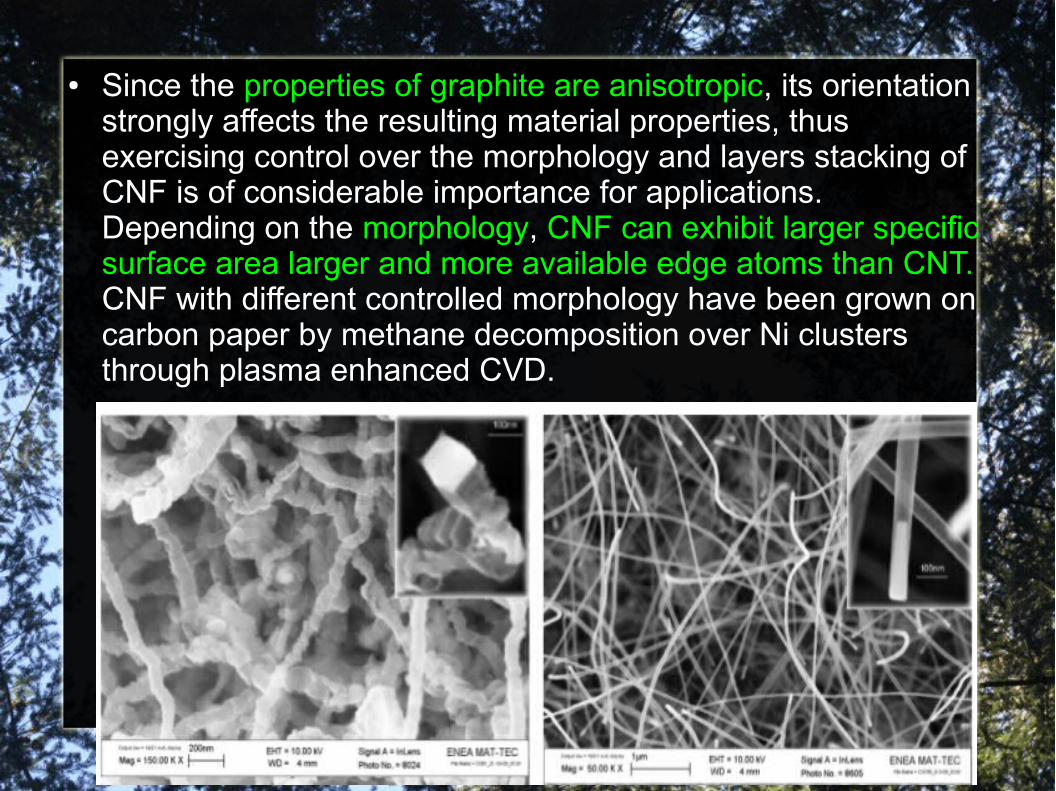
● Since the properties of graphite are anisotropic, its orientation strongly affects the resulting material properties, thus exercising control over the morphology and layers stacking of CNF is of considerable importance for applications. Depending on the morphology, CNF can exhibit larger specific surface area larger and more available edge atoms than CNT. CNF with different controlled morphology have been grown on carbon paper by methane decomposition over Ni clusters through plasma enhanced CVD.
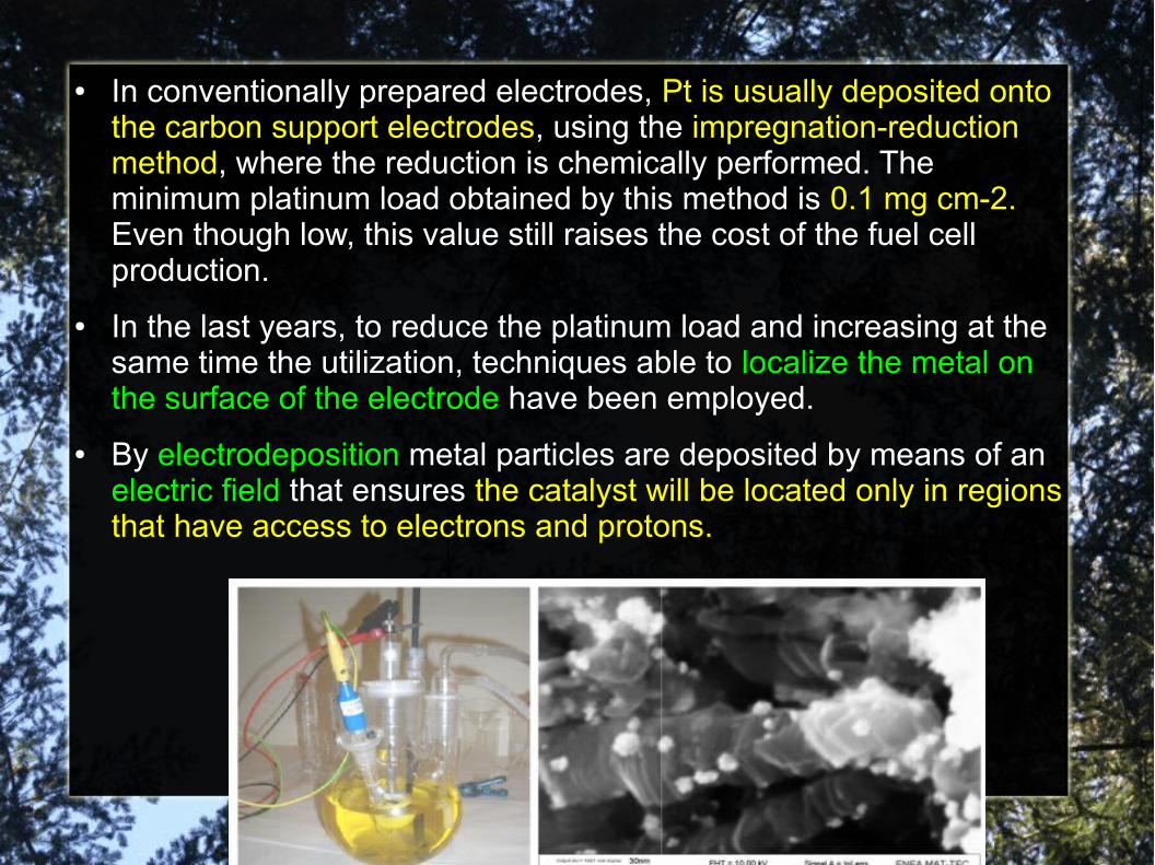
● In conventionally prepared electrodes, Pt is usually deposited onto the carbon support electrodes, using the impregnation-reduction method, where the reduction is chemically performed. The minimum platinum load obtained by this method is 0.1 mg cm-2. Even though low, this value still raises the cost of the fuel cell production.
● In the last years, to reduce the platinum load and increasing at the same time the utilization, techniques able to localize the metal on the surface of the electrode have been employed.
● By electrodeposition metal particles are deposited by means of an electric field that ensures the catalyst will be located only in regions that have access to electrons and protons.
● With this method the catalyst loading has been highly reduced. More recently sputter deposition technique has been examined as a means to obtain ultra low levels of catalyst loading. Electrodes ultra-low catalyzed with this technique have shown electrochemical performance comparable with that of the conventionally prepared catalyst, combined with an outstanding decrease of the Pt load down to 0.06 mg cm-2.
● A considerable reduction of the catalyst load has been also achieved by the electrodeposition of Pt clusters onto CNF. Moreover, it was found that electrochemical performance and stability of Pt/CNF electrodes was strongly related to the graphene related sheets arrangement.
● The platelet CNF showed the highest activity attributed to the higher ratio of edge to basal atoms and, as a consequence, larger number of active sites for electron transfer, a very large working surface area, a more uniform dispersion of Pt particles with more smaller size and a higher performance for the methanol oxidation reaction. Therefore, the platelet CNF are good candidate for catalyst support in PEFC with better performances with respect to commercial supports.
●
4)Other limitations.
● An additional problem hindering the real penetration of PEFC into the market is the CO induced poisoning of the platinum, which implies the need of high platinum load in order to obtain reasonable performances. The development of more tolerant catalysts is required and the research is focused on the development of binary alloys, where the second component is thought to inhibit the CO adsorption on the catalyst surface.
● To this aim, electrodes have been catalyzed with sputtered PtAu clusters. The catalyst resulted localized only on the uppermost surface, combining low loading levels with higher electrochemical performance and stability compared to PtAu deposited onto commercial carbon supports.
● Although hydrogen has a high energy density by weight, it has a low energy density by volume as compared to hydrocarbon-based fuel cells. Thus, hydrogen storage is one of the bottlenecks for hydrogen fuel cell development since high-pressure compressed gas tanks are large and heavy. In addition, compressing hydrogen to high pressures require energy as well, defeating some of the cost benefits with fuel cells. Liquid hydrogen storage, which does not have a great energy density by volume as compared to hydrocarbon, also requires cryogenic storage – a bulky and expensive option.
● Hydrogen fuel cell technologies will not be adopted unless the hydrogen gas storage tanks can be improved to decrease size and weight.
● Nanotechnologies have potential for use in advancing hydrogen storage technologies to create breakthroughs in weight and size. They are exploring nanomaterials and microscale designs that may help improve hydrogen storage.
● The nanomaterials provides large surfaces areas to which hydrogen adsorbs; consequently, the materials improve the energy density by volume. Other researchers have investigated activated carbon, carbon nanotubes, and metal organic frameworks. We are extending the range of materials to other carbon-based structures and sources. We will also investigate the effect of doping of the materials to improve adsorption.