Embed Size (px)
Citation preview

Wideband planar plate monopole antenna 487
Wideband planar plate monopole antenna
H. R. Hassani and S. M. Mazinani
x
Wideband planar plate monopole antenna
H. R. Hassani and S. M. Mazinani
Electrical & Electronic Eng. Dept., Shahed University Tehran-IRAN
1. Introduction
The use of a single wideband antenna which covers a wide range of frequencies is very desirable for many applications including wireless and high data rate communication, position and tracking, sensing and imaging, and radar. Planar plate monopole antenna is a candidate. They are interesting due to their broad impedance bandwidth, linearly polarized omnidirectional azumuthal radiation pattern and are very cost effective to construct. They are planar structure, where a thin planar metal element can be used instead of the traditional wire element of a monopole antenna. It was first described by (Dubost & Zisler, 1976), who observed the wide impedance characteristics of this antenna. The antenna is capable of covering the 2-18GHz band with good radiating properties. This antenna can be used in various wireless communication applications, ranging from GSM1800, PCS1900, DCS, WCDMA/UMTS, the 2.45/5.2/5.8 GHz ISM bands, UNII, DECT, WLANs, the European Hiper LAN I, II, Bluetooth technology, and wireless local loop (WLL) 3.4-3.6 GHz and 10 GHz and UWB (3.1–10.6GHz). In this chapter, important developments to the basic geometry of the planar plate monopole antenna are provided and discussed with respect to their impedance bandwidth, current distribution and their radiation patterns. Formulas that can be used to evaluate the frequency corresponding to the lower edge of the impedance bandwidth will also be provided. The basic antenna structures considered include the circular plate which yield very large impedance bandwidth and the rectangular (square) plate that provides a lower impedance bandwidth than the circular plate but its radiation pattern suffers less degradation over the bandwidth. Thus, most of the works reported in the literature on the subject of the planar plate monopole antennas are on ways of increasing the impedance bandwidth of the rectangular (square) monopole plate. This include: the bevelled square plate; the pin shorted square plate; dual fed and triple fed square elements and the rectangular monopole antenna loaded with small rectangular plates. Addition of slots to the planar monopole resulting in multiple frequency notch behaviour are also considered and discussed.
23
www.intechopen.com

Passive Microwave Components and Antennas488
2. Planar Circular Monopole Antenna
One of the earliest monopole shapes whose properties were studied in the literature is the circular disc monopole antenna (Agrawall et al., 1998). Fig. 1 shows a metallic circular disc monopole, CDM, and an elliptical disc monopole, EDM, placed above a flat ground plane and fed through a coaxial feed via a narrow strip. VSWR results for an optimized disk, CDM and EDM, of thickness 1 mm above a ground plane of size 30 × 30 cm2 are shown in Fig. 2. For the CDM antenna the height g = 1 mm gives the highest bandwidth ranging 1.17 to 12 GHz for a VSWR < 2. This range corresponds to bandwidth ratio of 1:10.2. The EDM antenna considered has an area equal to that of the CDM for comparison purposes. Fig. 2 also shows the VSWR of two EDM antennas with dimension a = 26 mm and b = 24 mm (with aspect ratio of 1.1) when fed either along the minor or the major axis. If the aspect ratio increases from 1.1 to 1.4, it can be shown that the bandwidth of the antenna decreases, Table 1.
Fig. 1. Geometry of a circular and an elliptical disc planar monopole antenna. (Source: Agrawall et al., 1998).
Fig. 2. VSWR of circular and elliptical disc planar monopole antenna. (Source: Agrawall et al., 1998).
Config. a (mm)
b (mm)
Measured Freq. range for VSWR < 2 (GHz)
Theoretical Lower freq. for VSWR < 2
(GHz)
Bandwidth ratio
CDM 26 25 1.17 – 12.00 1.28 1:10.2 EDM1 EDM2 26 24 1.21 – 13
1.20 – 12.50 1.31 1.24
1:10.7 1:10.4
EDM1 EDM2 27 23 1.38 – 11.49
1.13 – 12.00 1.37 1.20
1:8.3 1:10.6
EDM1 EDM2 28 22 1.37 – 11.30
1.08 – 11.43 1.41 1.17
1:8.2 1:10.6
EDM1 EDM2 29 21 1.58 – 10.45
1.09 – 10.45 1.46 1.13
1:6.6 1:9.6
Table 1. VSWR bandwidth of CDM and EDM. (Source: Agrawall et al., 1998).
The frequency corresponding to the lower edge of the bandwidth of these monopole antennas can be determined approximately by equating the area of the planar configuration to that of a cylindrical wire of height l (which is same as that of planar disc height) with equivalent radius r given by 2πrl = πab. The length of a standard cylindrical monopole for real input impedance is given by (Balanis, 1982)
l = 0.24 ×λ × F (1)
Where )1/()(rl
rlF . From the above equations, the resonant frequency is given by
f = c/λ = (30×0.24) / (l+r) GHz (2)
where l and r are in centimetres. The theoretical frequencies calculated using the above equations for the discs considered in Table 1 shows agreement within ± 8 %. From Table 1 it is seen that the simple circular disc can provide a very high impedance bandwidth. Fig. 3 shows the simulated E- and H-plane radiation patterns of the CDM antenna at three different frequencies over the bandwidth. From these results it can be seen that as the frequency increases from 2.5 to 9.0 GHz, the direction of maxima of the conical beam of the E-plane pattern varies from 30o to 60o from elevation, whereas the H-plane pattern remains nearly omnidirectional with maximum variation in azimuth increasing from 4 to 7 dB. The slight distortion in the patterns might be attributed to shape of the disc monopole, reflections from metallic surfaces and edge diffraction. These patterns are similar to that of a vertical linear monopole antenna of equivalent height on a finite ground plane, (Balanis, 1982).
Fig. 3. The normalized radiation pattern of the CDM antenna (a) E-plane and (b) H-plane Fig. 4 shows the distribution of current along the CDM antenna at two frequencies in the bandwidth. It can be seen that at the lower frequency, the current on the disc is uniform, but at the higher frequency, the current points in different directions. Thus, at higher frequency, we do not get a good omnidirectional pattern in the H-plane and the direction of the beam peak in the E-plane pattern varies from 30o to 60o from elevation.
www.intechopen.com

Wideband planar plate monopole antenna 489
2. Planar Circular Monopole Antenna
One of the earliest monopole shapes whose properties were studied in the literature is the circular disc monopole antenna (Agrawall et al., 1998). Fig. 1 shows a metallic circular disc monopole, CDM, and an elliptical disc monopole, EDM, placed above a flat ground plane and fed through a coaxial feed via a narrow strip. VSWR results for an optimized disk, CDM and EDM, of thickness 1 mm above a ground plane of size 30 × 30 cm2 are shown in Fig. 2. For the CDM antenna the height g = 1 mm gives the highest bandwidth ranging 1.17 to 12 GHz for a VSWR < 2. This range corresponds to bandwidth ratio of 1:10.2. The EDM antenna considered has an area equal to that of the CDM for comparison purposes. Fig. 2 also shows the VSWR of two EDM antennas with dimension a = 26 mm and b = 24 mm (with aspect ratio of 1.1) when fed either along the minor or the major axis. If the aspect ratio increases from 1.1 to 1.4, it can be shown that the bandwidth of the antenna decreases, Table 1.
Fig. 1. Geometry of a circular and an elliptical disc planar monopole antenna. (Source: Agrawall et al., 1998).
Fig. 2. VSWR of circular and elliptical disc planar monopole antenna. (Source: Agrawall et al., 1998).
Config. a (mm)
b (mm)
Measured Freq. range for VSWR < 2 (GHz)
Theoretical Lower freq. for VSWR < 2
(GHz)
Bandwidth ratio
CDM 26 25 1.17 – 12.00 1.28 1:10.2 EDM1 EDM2 26 24 1.21 – 13
1.20 – 12.50 1.31 1.24
1:10.7 1:10.4
EDM1 EDM2 27 23 1.38 – 11.49
1.13 – 12.00 1.37 1.20
1:8.3 1:10.6
EDM1 EDM2 28 22 1.37 – 11.30
1.08 – 11.43 1.41 1.17
1:8.2 1:10.6
EDM1 EDM2 29 21 1.58 – 10.45
1.09 – 10.45 1.46 1.13
1:6.6 1:9.6
Table 1. VSWR bandwidth of CDM and EDM. (Source: Agrawall et al., 1998).
The frequency corresponding to the lower edge of the bandwidth of these monopole antennas can be determined approximately by equating the area of the planar configuration to that of a cylindrical wire of height l (which is same as that of planar disc height) with equivalent radius r given by 2πrl = πab. The length of a standard cylindrical monopole for real input impedance is given by (Balanis, 1982)
l = 0.24 ×λ × F (1)
Where )1/()(rl
rlF . From the above equations, the resonant frequency is given by
f = c/λ = (30×0.24) / (l+r) GHz (2)
where l and r are in centimetres. The theoretical frequencies calculated using the above equations for the discs considered in Table 1 shows agreement within ± 8 %. From Table 1 it is seen that the simple circular disc can provide a very high impedance bandwidth. Fig. 3 shows the simulated E- and H-plane radiation patterns of the CDM antenna at three different frequencies over the bandwidth. From these results it can be seen that as the frequency increases from 2.5 to 9.0 GHz, the direction of maxima of the conical beam of the E-plane pattern varies from 30o to 60o from elevation, whereas the H-plane pattern remains nearly omnidirectional with maximum variation in azimuth increasing from 4 to 7 dB. The slight distortion in the patterns might be attributed to shape of the disc monopole, reflections from metallic surfaces and edge diffraction. These patterns are similar to that of a vertical linear monopole antenna of equivalent height on a finite ground plane, (Balanis, 1982).
Fig. 3. The normalized radiation pattern of the CDM antenna (a) E-plane and (b) H-plane Fig. 4 shows the distribution of current along the CDM antenna at two frequencies in the bandwidth. It can be seen that at the lower frequency, the current on the disc is uniform, but at the higher frequency, the current points in different directions. Thus, at higher frequency, we do not get a good omnidirectional pattern in the H-plane and the direction of the beam peak in the E-plane pattern varies from 30o to 60o from elevation.
www.intechopen.com

Passive Microwave Components and Antennas490
Fig. 4. The distribution of current along the circular planar monopole antenna at (a) 2.5 GHz and (b) 9 GHz
3. Square Planar Monopole Antenna
One of the simple planar monopole (PM) antenna shapes that have received a lot of attentions is the square (or rectangular) plate, Fig. 5. The square element is easier to deal with during the optimization process. The planar element is located a distance g above a ground plane, and is fed by a narrow strip through a SMA connector. The bandwidth of the PM antenna is set mainly by the radiating element dimensions, L and to obtain the maximum impedance bandwidth a suitable feed gap separation, g is required.
Fig. 5. The square planar monopole plate antenna above a square ground plane The effect that the square PM antenna dimension and its separation from ground have on the impedance bandwidth can be obtained through the study of the return loss results, (Ammann, 1999); (Ammann & Chen, 2003a). In all cases the thickness of the planar plate monopole is 0.5 mm copper sheet and the square ground plane considered is of side 100 mm and the SMA connector has a feed-probe diameter of 1.2 mm. Table 2 gives for a square plate planar monopole of various dimensions, L, the lower and upper frequency limits, and hence, the bandwidth based on 10 dB return loss. In each case the feed gap has been optimized for the highest bandwidth. As is typical for monopole antennas, the lower edge of the impedance bandwidth is inversely proportional to the overall length of the element. In the case of PM antenna, the overall length also includes the feed gap (i.e. L + g). Typically, the length of the square PM
corresponds to about 0.21 of a free space wavelength at the lower-edge frequency; this is shorter than a quarter-wave monopole due to a reduced length-to-radius factor.
Square Size L (mm)
Frequency Limits (GHz)
Bandwidth (MHz)
Optimum Feed Gap (mm)
60 1.16 – 2.08 920 3 55 1.23 – 2.19 960 3 50 1.34 – 2.35 1010 3 45 1.44 – 2.59 1150 2.5 40 1.59 – 2.96 1370 2.5 35 1.86 – 3.53 1670 2.5 30 1.98 – 4.05 2090 2.5 25 2.38 – 5.20 2820 2.5 20 2.68 – 6.50 3820 2.2
Table 2. The impedance bandwidth for the square element of various dimensions, L. (Source: Ammann & Chen, 2003a). The lower frequency limit of a rectangular radiating element, size L×W, can be determined from the following simple formula:
gWLf l
2.7
(3)
The above results shows that the impedance bandwidth is dependent on the feed gap, g and this gap must he optimized for maximum bandwidth. The frequency corresponding to the lower edge of the bandwidth is fairly independent of the feed gap, g, but the upper frequency is heavily dependent on it. This can be seen in Fig. 6, which shows the return loss for a 30 × 30 mm2 square monopole with feed gaps of 0.8, 1.6, and 2.5 mm.
Fig. 6. The return loss of a 30 mm square monopole with feed gaps of 0.8 (dashed), 1.6 (dot-dashed), and 2.5 mm (solid). (Source: Ammann & Chen, 2003a). Fig. 7 shows the E- and H-plane radiation patterns of the square PM antenna at various frequencies over the bandwidth.
www.intechopen.com

Wideband planar plate monopole antenna 491
Fig. 4. The distribution of current along the circular planar monopole antenna at (a) 2.5 GHz and (b) 9 GHz
3. Square Planar Monopole Antenna
One of the simple planar monopole (PM) antenna shapes that have received a lot of attentions is the square (or rectangular) plate, Fig. 5. The square element is easier to deal with during the optimization process. The planar element is located a distance g above a ground plane, and is fed by a narrow strip through a SMA connector. The bandwidth of the PM antenna is set mainly by the radiating element dimensions, L and to obtain the maximum impedance bandwidth a suitable feed gap separation, g is required.
Fig. 5. The square planar monopole plate antenna above a square ground plane The effect that the square PM antenna dimension and its separation from ground have on the impedance bandwidth can be obtained through the study of the return loss results, (Ammann, 1999); (Ammann & Chen, 2003a). In all cases the thickness of the planar plate monopole is 0.5 mm copper sheet and the square ground plane considered is of side 100 mm and the SMA connector has a feed-probe diameter of 1.2 mm. Table 2 gives for a square plate planar monopole of various dimensions, L, the lower and upper frequency limits, and hence, the bandwidth based on 10 dB return loss. In each case the feed gap has been optimized for the highest bandwidth. As is typical for monopole antennas, the lower edge of the impedance bandwidth is inversely proportional to the overall length of the element. In the case of PM antenna, the overall length also includes the feed gap (i.e. L + g). Typically, the length of the square PM
corresponds to about 0.21 of a free space wavelength at the lower-edge frequency; this is shorter than a quarter-wave monopole due to a reduced length-to-radius factor.
Square Size L (mm)
Frequency Limits (GHz)
Bandwidth (MHz)
Optimum Feed Gap (mm)
60 1.16 – 2.08 920 3 55 1.23 – 2.19 960 3 50 1.34 – 2.35 1010 3 45 1.44 – 2.59 1150 2.5 40 1.59 – 2.96 1370 2.5 35 1.86 – 3.53 1670 2.5 30 1.98 – 4.05 2090 2.5 25 2.38 – 5.20 2820 2.5 20 2.68 – 6.50 3820 2.2
Table 2. The impedance bandwidth for the square element of various dimensions, L. (Source: Ammann & Chen, 2003a). The lower frequency limit of a rectangular radiating element, size L×W, can be determined from the following simple formula:
gWLf l
2.7
(3)
The above results shows that the impedance bandwidth is dependent on the feed gap, g and this gap must he optimized for maximum bandwidth. The frequency corresponding to the lower edge of the bandwidth is fairly independent of the feed gap, g, but the upper frequency is heavily dependent on it. This can be seen in Fig. 6, which shows the return loss for a 30 × 30 mm2 square monopole with feed gaps of 0.8, 1.6, and 2.5 mm.
Fig. 6. The return loss of a 30 mm square monopole with feed gaps of 0.8 (dashed), 1.6 (dot-dashed), and 2.5 mm (solid). (Source: Ammann & Chen, 2003a). Fig. 7 shows the E- and H-plane radiation patterns of the square PM antenna at various frequencies over the bandwidth.
www.intechopen.com

Passive Microwave Components and Antennas492
Upon comparison of the square PM antenna with the circular PM antenna one can see that the circular plate provides higher impedance bandwidth but, unlike the circular PM antenna the patterns of the square (or rectangular) plate monopole are fairly stable with frequency. As such, majority of the works, reported in the literature, carried out on the PM antennas use the square (or rectangular) shaped plates.
Fig. 7. The radiation pattern of the square monopole antenna at different frequencies, (a) E- (b) H-plane To increase the impedance bandwidth of the square PM antenna, various techniques that change the basic shape of the monopole plate has been reported. These techniques include: cutting one or both edges of the monopole plate near the ground plane, so called bevelling; shorting the monopole plate to the ground; exciting the monopole plate antenna at two or three feeding points; and loading the monopole plate at its radiating edges with small rectangular plates. In the following these techniques are given.
4. Rectangular planar monopole antenna with bevel
A significant increase in impedance bandwidth can be achieved by cutting, or bevelling, the edge of the square monopole near the ground plane on one or both sides of the feed probe (Ammann, 2001), as shown in Fig. 8.
Fig. 8. Planar square monopole antenna with (a) asymmetrical and (b) symmetrical bevel
The basic antenna structure considered here is square shaped and is of side 25 mm, and thickness 0.2 mm, placed above a 150 mm square ground plane and fed via an SMA connector. The upper and lower edge frequencies of this simple square antenna are 2.35 and 4.95 GHz, representing an impedance bandwidth ratio of 2.1:1. One of the edges of the PM antenna can be cut, asymmetrically bevelled, and fine control of the impedance bandwidth can be achieved by varying the angle of the bevel. If the square element is bevelled by α = 10o on one side of the feed probe, the upper edge frequency increases to 5.3 GHz. If the bevel is increased to α = 40o, the upper edge frequency increases to 6.0 GHz, while the lower edge frequency drops to 2.175 GHz. This represents an impedance bandwidth ratio of 2.75:1. If the planar element is symmetrically bevelled on both sides of the feed probe, the upper edge frequency is increased further. For a symmetrical bevel of α = 40o a significant increase in the upper edge frequency, 12.5 GHz, can be achieved, representing an impedance bandwidth ratio of 5.75:1. Further increases in bevel do not increase the impedance bandwidth. The upper and lower edge frequencies for both asymmetrically and symmetrically bevelled PM antennas are given in Table 3.
Bevel α (degrees)
Bandwidth (GHz) Asymmetrically Bevelled
Bandwidth (GHz) Symmetrically Bevelled
0 2.35 – 4.95 2.35 – 4.95 10 2.20 – 5.30 2.12 – 5.95 20 2.19 – 5.75 2.11 – 6.75 30 2.17 – 5.97 2.10 – 7.25 40 2.17 – 6.00 2.10 – 12.50
Table 3. The impedance bandwidth of the bevelled square PM antenna. (Source: Ammann, 2001). The radiation patterns of the asymmetric and symmetric bevelled monopole antenna are nearly constant with frequency over the bandwidth. The radiation patterns are quasi omnidirectional over the impedance bandwidth, the bevel has no noticeable effect on radiation patterns (less than a decibel). Fig. 9(a) shows the E-plane patterns of the symmetric bevelled monopole antenna at two frequencies. Fig. 9(b) shows the H-plane pattern, where the pattern is omnidirectional to within ±1.6 and ±2.9 dB at 2.4 and 5.8 GHz, respectively.
Fig. 9. Radiation patterns of the symmetric bevelled square monopole with α = 40o (a) E-plane (b) H-plane (c) H-plane at higher frequencies. (Source: Ammann, 2001).
www.intechopen.com

Wideband planar plate monopole antenna 493
Upon comparison of the square PM antenna with the circular PM antenna one can see that the circular plate provides higher impedance bandwidth but, unlike the circular PM antenna the patterns of the square (or rectangular) plate monopole are fairly stable with frequency. As such, majority of the works, reported in the literature, carried out on the PM antennas use the square (or rectangular) shaped plates.
Fig. 7. The radiation pattern of the square monopole antenna at different frequencies, (a) E- (b) H-plane To increase the impedance bandwidth of the square PM antenna, various techniques that change the basic shape of the monopole plate has been reported. These techniques include: cutting one or both edges of the monopole plate near the ground plane, so called bevelling; shorting the monopole plate to the ground; exciting the monopole plate antenna at two or three feeding points; and loading the monopole plate at its radiating edges with small rectangular plates. In the following these techniques are given.
4. Rectangular planar monopole antenna with bevel
A significant increase in impedance bandwidth can be achieved by cutting, or bevelling, the edge of the square monopole near the ground plane on one or both sides of the feed probe (Ammann, 2001), as shown in Fig. 8.
Fig. 8. Planar square monopole antenna with (a) asymmetrical and (b) symmetrical bevel
The basic antenna structure considered here is square shaped and is of side 25 mm, and thickness 0.2 mm, placed above a 150 mm square ground plane and fed via an SMA connector. The upper and lower edge frequencies of this simple square antenna are 2.35 and 4.95 GHz, representing an impedance bandwidth ratio of 2.1:1. One of the edges of the PM antenna can be cut, asymmetrically bevelled, and fine control of the impedance bandwidth can be achieved by varying the angle of the bevel. If the square element is bevelled by α = 10o on one side of the feed probe, the upper edge frequency increases to 5.3 GHz. If the bevel is increased to α = 40o, the upper edge frequency increases to 6.0 GHz, while the lower edge frequency drops to 2.175 GHz. This represents an impedance bandwidth ratio of 2.75:1. If the planar element is symmetrically bevelled on both sides of the feed probe, the upper edge frequency is increased further. For a symmetrical bevel of α = 40o a significant increase in the upper edge frequency, 12.5 GHz, can be achieved, representing an impedance bandwidth ratio of 5.75:1. Further increases in bevel do not increase the impedance bandwidth. The upper and lower edge frequencies for both asymmetrically and symmetrically bevelled PM antennas are given in Table 3.
Bevel α (degrees)
Bandwidth (GHz) Asymmetrically Bevelled
Bandwidth (GHz) Symmetrically Bevelled
0 2.35 – 4.95 2.35 – 4.95 10 2.20 – 5.30 2.12 – 5.95 20 2.19 – 5.75 2.11 – 6.75 30 2.17 – 5.97 2.10 – 7.25 40 2.17 – 6.00 2.10 – 12.50
Table 3. The impedance bandwidth of the bevelled square PM antenna. (Source: Ammann, 2001). The radiation patterns of the asymmetric and symmetric bevelled monopole antenna are nearly constant with frequency over the bandwidth. The radiation patterns are quasi omnidirectional over the impedance bandwidth, the bevel has no noticeable effect on radiation patterns (less than a decibel). Fig. 9(a) shows the E-plane patterns of the symmetric bevelled monopole antenna at two frequencies. Fig. 9(b) shows the H-plane pattern, where the pattern is omnidirectional to within ±1.6 and ±2.9 dB at 2.4 and 5.8 GHz, respectively.
Fig. 9. Radiation patterns of the symmetric bevelled square monopole with α = 40o (a) E-plane (b) H-plane (c) H-plane at higher frequencies. (Source: Ammann, 2001).
www.intechopen.com

Passive Microwave Components and Antennas494
The maximum gain at 2.4 GHz is 2.7 dBi at θ = 52o but is 1.2 dBi at θ = 90o. At 5.8 GHz, the maximum gain is 4.6 dBi at θ = 65o, and is only 2.4 dBi at θ = 90o. The pattern of the 40o symmetrically bevelled element suffers some degradation at higher frequencies, Fig. 9(c). At these frequencies, the dimensions of this antenna are no longer small compared to a wavelength, and the radiation pattern exhibits some directivity. The increase in impedance bandwidth of the PM antenna through bevelling can be described through Transmission Line Modelling (TLM) (Valderas et al., 2006). The study of the current flow on a PM antenna reveals that it is mostly concentrated in the vertical and horizontal edges. Fig. 10 shows the current amplitude distribution for a simple square PM antenna. The horizontal current distribution is observed to be focused on the bottom edge of the PM antenna, near the ground, where it is greater in amplitude than the vertical component. Thus, this edge will hardly contribute to the radiation. As such, the structure could be modelled as a transmission line loaded with the radiation resistance of the antenna Fig. 11a. Transmission line broadband matching techniques could then be applied to the antenna. The relations between the geometrical parameters of the monopole and the transmission lines are shown in Table 4. From the TLM point of view, bevelling technique is equivalent to forcing the horizontal transmission line to exhibit characteristic impedance that is a function of the distance from the feed point. On the other hand, continuously tapered lines are suitable techniques to achieve broadband matching. Both of these aspects are joined in the TLM applied to the PM antenna. A bevel, indeed, would act as a tapered line since a continuously increasing height above the ground plane means that the characteristic impedance will also increase continuously in a tapered line fashion, Fig. 11b.
Fig. 10. The current amplitude distribution (a) absolute, (b) horizontal and vertical components. (Source: Valderas et al., 2006).
Fig. 11. Qualitative model of the (a) PM antenna (b) PM antenna with bevel based on TLM
PM antenna TLM g Zo
2L x
Radiating edge ZL Table. 4. Relation between the planar monopole and transmission line parameters. (Source: Valderas et al., 2006).
5. Shorted planar monopole antenna
The monopole antenna with shorting post is shown in Fig. 12. The shorting post is located at one comer of the planar element, and could be cylindrical with about 1 mm diameter, or a strip with width 2 mm.
Fig. 12. Square planar monopole plate antenna with shorting post at one corner Compared to the simple monopole antenna the feed-gap separation in the present structure needs to be reduced for optimum impedance bandwidth. Similar to other antennas, for a given planar monopole antenna, the use of shorting post has been shown to reduce the lower-edge frequency by introducing an extra mode, (Lee et al., 1999); (Ammann & Chen, 2003a). The presence of the post increases the antenna bandwidth and makes it smaller in height. Fig. 13 shows the return loss for a 25 × 25 mm2 PM antenna with and without the shorting strip, which shows an impedance bandwidth of 114% and 76%, respectively. The asymmetry in the structure produces some distortion in the radiation pattern, particularly at the higher frequencies, Fig. 14.
Fig. 13. Return loss of a 25mm square PM antenna, with (solid) and without (dash) the shorting post. (Source: Ammann & Chen, 2003a).
Fig. 14. Radiation patterns of the shorted square monopole antenna (a) E-plane (b) H-plane.
www.intechopen.com

Wideband planar plate monopole antenna 495
The maximum gain at 2.4 GHz is 2.7 dBi at θ = 52o but is 1.2 dBi at θ = 90o. At 5.8 GHz, the maximum gain is 4.6 dBi at θ = 65o, and is only 2.4 dBi at θ = 90o. The pattern of the 40o symmetrically bevelled element suffers some degradation at higher frequencies, Fig. 9(c). At these frequencies, the dimensions of this antenna are no longer small compared to a wavelength, and the radiation pattern exhibits some directivity. The increase in impedance bandwidth of the PM antenna through bevelling can be described through Transmission Line Modelling (TLM) (Valderas et al., 2006). The study of the current flow on a PM antenna reveals that it is mostly concentrated in the vertical and horizontal edges. Fig. 10 shows the current amplitude distribution for a simple square PM antenna. The horizontal current distribution is observed to be focused on the bottom edge of the PM antenna, near the ground, where it is greater in amplitude than the vertical component. Thus, this edge will hardly contribute to the radiation. As such, the structure could be modelled as a transmission line loaded with the radiation resistance of the antenna Fig. 11a. Transmission line broadband matching techniques could then be applied to the antenna. The relations between the geometrical parameters of the monopole and the transmission lines are shown in Table 4. From the TLM point of view, bevelling technique is equivalent to forcing the horizontal transmission line to exhibit characteristic impedance that is a function of the distance from the feed point. On the other hand, continuously tapered lines are suitable techniques to achieve broadband matching. Both of these aspects are joined in the TLM applied to the PM antenna. A bevel, indeed, would act as a tapered line since a continuously increasing height above the ground plane means that the characteristic impedance will also increase continuously in a tapered line fashion, Fig. 11b.
Fig. 10. The current amplitude distribution (a) absolute, (b) horizontal and vertical components. (Source: Valderas et al., 2006).
Fig. 11. Qualitative model of the (a) PM antenna (b) PM antenna with bevel based on TLM
PM antenna TLM g Zo
2L x
Radiating edge ZL Table. 4. Relation between the planar monopole and transmission line parameters. (Source: Valderas et al., 2006).
5. Shorted planar monopole antenna
The monopole antenna with shorting post is shown in Fig. 12. The shorting post is located at one comer of the planar element, and could be cylindrical with about 1 mm diameter, or a strip with width 2 mm.
Fig. 12. Square planar monopole plate antenna with shorting post at one corner Compared to the simple monopole antenna the feed-gap separation in the present structure needs to be reduced for optimum impedance bandwidth. Similar to other antennas, for a given planar monopole antenna, the use of shorting post has been shown to reduce the lower-edge frequency by introducing an extra mode, (Lee et al., 1999); (Ammann & Chen, 2003a). The presence of the post increases the antenna bandwidth and makes it smaller in height. Fig. 13 shows the return loss for a 25 × 25 mm2 PM antenna with and without the shorting strip, which shows an impedance bandwidth of 114% and 76%, respectively. The asymmetry in the structure produces some distortion in the radiation pattern, particularly at the higher frequencies, Fig. 14.
Fig. 13. Return loss of a 25mm square PM antenna, with (solid) and without (dash) the shorting post. (Source: Ammann & Chen, 2003a).
Fig. 14. Radiation patterns of the shorted square monopole antenna (a) E-plane (b) H-plane.
www.intechopen.com

Passive Microwave Components and Antennas496
Fig. 15 shows the current distribution on the monopole antenna with and without the shorting post at one corner. It can be seen that for the simple PM antenna currents distribute symmetrically around the feed point. When the shorting post is added to the bottom edge, current distribution on the antenna becomes asymmetric and current is strong near the shorted edge and ground plane. Thus, the radiation from this edge is lower than the opposite edge. Because of this asymmetric, the radiation pattern becomes asymmetric and degraded in the side of shorting.
Fig. 15. Current distribution on a square monopole plate (a) without and (b) with shorting post
6. Shorted planar monopole antenna with bevel
It was shown earlier that addition of a bevel to one side of a square planar monopole, SPM antenna increases the upper edge frequency significantly and increases the bandwidth of the antenna. Control of this upper frequency is possible by adjusting the bevel angle. The addition of a shorting post to one side of the planar monopole also increases the bandwidth. A combination of shorting post and bevel can yield an impedance bandwidth of 800 MHz to 11 GHz, which is suitable for combinations of cellular and UWB systems (Ammann & Chen, 2003b). Fig. 16 shows a shorted PM antenna with bevel. The antenna is constructed using 0.2 mm thick copper sheet on a 200 mm square ground plane and fed via an SMA connector. The square plate dimension, L, is 60 mm, the shorting strip is 2 mm wide and the feed gap g is 1.2 mm. The monopole plate is bevelled on the side opposite the shorting strip. The VSWR for the SPM antenna and SPM with shorting strip, SHPM, and SHPM with bevel, SHPMB, are shown in Fig. 17. As can be seen the shorting strip reduces the lower-edge frequency and the bevel raises the upper-edge frequency significantly. The plot shows the effect of introducing the bevel and shorting strip on the impedance bandwidth. The feed gaps are optimized for maximum bandwidth in each case. The 3 : 1 VSWR impedance bandwidths are 890–2250 MHz for the SPM antenna, 730–2500 MHz for the SHPM antenna and 850 MHz to >10.5 GHz for the SHPMB antenna.
Fig. 16. The geometry of the shorted PM antenna with bevel
Fig. 17. The VSWR for the SPM, SHPM and SHPMB antennas. (Source: Ammann & Chen, 2003b) VSWR plots over the range 0.5–10.5 GHz are shown in Fig. 18(a) for the SPM antenna with bevel angles of α = 0o to α = 40o. It can be seen that the VSWR variation with frequency is reduced by the addition of the bevel. Fig. 18(b) shows the VSWR for the SPM antenna with both bevel and shorting strip. It can be observed that the VSWR remains below 3: 1 over most of the frequency range when α = 10o and 20o. The bevel tends to increase the VSWR slightly at the lower frequencies but reduces the VSWR significantly at higher frequencies. For α = 10o, the lower and upper-edge frequencies (3: 1 VSWR) are 790 MHz and >10.5 GHz, respectively. The VSWR is slightly greater than 3: 1 only in the regions from 1.05–1.22 GHz and from 7.5–8.2 GHz. The radiation patterns are shown in Fig. 19. The plots indicate nearly omnidirectional patterns in the H plane and typical monopole patterns in the E plane cuts at the lower frequencies. The plots are given at 900 MHz, 2.4, and 5.8 GHz.
Fig. 18. VSWR for the simple planar monopole with bevel (a) without and (b) with shorting strip. (Source: Ammann & Chen, 2003b)
www.intechopen.com

Wideband planar plate monopole antenna 497
Fig. 15 shows the current distribution on the monopole antenna with and without the shorting post at one corner. It can be seen that for the simple PM antenna currents distribute symmetrically around the feed point. When the shorting post is added to the bottom edge, current distribution on the antenna becomes asymmetric and current is strong near the shorted edge and ground plane. Thus, the radiation from this edge is lower than the opposite edge. Because of this asymmetric, the radiation pattern becomes asymmetric and degraded in the side of shorting.
Fig. 15. Current distribution on a square monopole plate (a) without and (b) with shorting post
6. Shorted planar monopole antenna with bevel
It was shown earlier that addition of a bevel to one side of a square planar monopole, SPM antenna increases the upper edge frequency significantly and increases the bandwidth of the antenna. Control of this upper frequency is possible by adjusting the bevel angle. The addition of a shorting post to one side of the planar monopole also increases the bandwidth. A combination of shorting post and bevel can yield an impedance bandwidth of 800 MHz to 11 GHz, which is suitable for combinations of cellular and UWB systems (Ammann & Chen, 2003b). Fig. 16 shows a shorted PM antenna with bevel. The antenna is constructed using 0.2 mm thick copper sheet on a 200 mm square ground plane and fed via an SMA connector. The square plate dimension, L, is 60 mm, the shorting strip is 2 mm wide and the feed gap g is 1.2 mm. The monopole plate is bevelled on the side opposite the shorting strip. The VSWR for the SPM antenna and SPM with shorting strip, SHPM, and SHPM with bevel, SHPMB, are shown in Fig. 17. As can be seen the shorting strip reduces the lower-edge frequency and the bevel raises the upper-edge frequency significantly. The plot shows the effect of introducing the bevel and shorting strip on the impedance bandwidth. The feed gaps are optimized for maximum bandwidth in each case. The 3 : 1 VSWR impedance bandwidths are 890–2250 MHz for the SPM antenna, 730–2500 MHz for the SHPM antenna and 850 MHz to >10.5 GHz for the SHPMB antenna.
Fig. 16. The geometry of the shorted PM antenna with bevel
Fig. 17. The VSWR for the SPM, SHPM and SHPMB antennas. (Source: Ammann & Chen, 2003b) VSWR plots over the range 0.5–10.5 GHz are shown in Fig. 18(a) for the SPM antenna with bevel angles of α = 0o to α = 40o. It can be seen that the VSWR variation with frequency is reduced by the addition of the bevel. Fig. 18(b) shows the VSWR for the SPM antenna with both bevel and shorting strip. It can be observed that the VSWR remains below 3: 1 over most of the frequency range when α = 10o and 20o. The bevel tends to increase the VSWR slightly at the lower frequencies but reduces the VSWR significantly at higher frequencies. For α = 10o, the lower and upper-edge frequencies (3: 1 VSWR) are 790 MHz and >10.5 GHz, respectively. The VSWR is slightly greater than 3: 1 only in the regions from 1.05–1.22 GHz and from 7.5–8.2 GHz. The radiation patterns are shown in Fig. 19. The plots indicate nearly omnidirectional patterns in the H plane and typical monopole patterns in the E plane cuts at the lower frequencies. The plots are given at 900 MHz, 2.4, and 5.8 GHz.
Fig. 18. VSWR for the simple planar monopole with bevel (a) without and (b) with shorting strip. (Source: Ammann & Chen, 2003b)
www.intechopen.com
Passive Microwave Components and Antennas498
Fig. 19. The E and H-plane radiation patterns of the SHPMB antenna. (Source: Ammann & Chen, 2003b)
7. Monopole Antenna with a dual and triple Feeding Strip
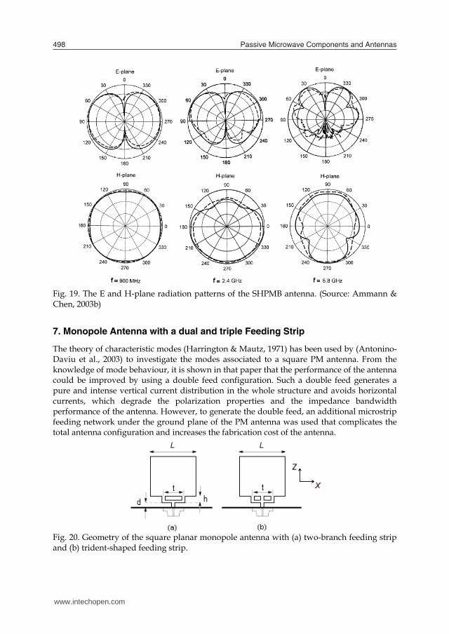
The theory of characteristic modes (Harrington & Mautz, 1971) has been used by (Antonino-Daviu et al., 2003) to investigate the modes associated to a square PM antenna. From the knowledge of mode behaviour, it is shown in that paper that the performance of the antenna could be improved by using a double feed configuration. Such a double feed generates a pure and intense vertical current distribution in the whole structure and avoids horizontal currents, which degrade the polarization properties and the impedance bandwidth performance of the antenna. However, to generate the double feed, an additional microstrip feeding network under the ground plane of the PM antenna was used that complicates the total antenna configuration and increases the fabrication cost of the antenna.
Fig. 20. Geometry of the square planar monopole antenna with (a) two-branch feeding strip and (b) trident-shaped feeding strip.
Following the above work, (Wong et al., 2005) suggested a simple dual and trident-shaped feeding strip suitable to achieve bandwidth enhancement of a square PM antenna. The planar monopole with the simple feeding strip is easily fabricated using a single metal plate and fed using a 50 ohm SMA connector and, in addition, no external feeding network is required, Fig. 20. In Fig. 20, a 0.2 mm thick square planar monopole antenna of side length L (40 mm) mounted above a ground plane of size 150 mm x150 mm is shown. The feeding strips are uniform and set to 2 mm. By adjusting the three parameters d, t and h, increase in the impedance bandwidth of the planar monopole antenna can be achieved. Parameter d controls the coupling between the ground plane and the lower edge of the planar monopole, which effectively varies the input reactance of the antenna. Thus impedance matching of the antenna can be fine-tuned, and optimized impedance bandwidth can be obtained for the antenna. The return loss for the simple planar monopole antenna with single feed, double branch feed and triple branch feed are shown in Fig. 21. With the size of the square plate set as above, the impedance bandwidth (10 dB return loss) would have a lower edge frequency of less than 1.5 GHz. For the double and triple branch feed structures by selecting the parameters t, h and d of the feeding strip to be 15, 3.5, and 1.0 mm, respectively, the upper edge frequency of the impedance bandwidth, for the double feed would be around 10.2 GHz and for the triple feed would be larger than 11.4 GHz. For the single feed PM antenna, to obtain the highest bandwidth, requires a feeding strip with d = 2.5 mm. It is seen that the triple branch feeding strip shows an impedance bandwidth of 1.276-11.448 GHz (a frequency ratio of 8.32), while the two-branch feeding strip shows a bandwidth of 1.354-10.182 GHz (a frequency ratio of 7.52) and that of the simple feeding strip is 1.455-3.286 GHz (a ratio of 2.26). The wide impedance bandwidth of the triple fed PM antenna makes the antenna suitable for application in the new broadband wireless metropolitan area network system using the IEEE 802.16a (2–11 GHz) standard. The current distribution behaviour on the planar monopole antenna for the three feeding structures is shown in Fig. 22. It is seen that the triple fed PM antenna provides a more uniform current distribution compared to a dual-feed design and a single-feed design. This leads to a much improved impedance bandwidth for the square planar monopole antenna. Radiation patterns of the triple fed planar monopole antenna are shown in Fig. 23 at three different frequencies of 2, 6 and 10 GHz.
Fig. 21. The return loss of the planar monopole antennas with a trident-shaped feeding strip, a two-branch feeding strip and a simple feeding strip. (Source: Wong et al., 2005).
www.intechopen.com

Wideband planar plate monopole antenna 499
Fig. 19. The E and H-plane radiation patterns of the SHPMB antenna. (Source: Ammann & Chen, 2003b)
7. Monopole Antenna with a dual and triple Feeding Strip
The theory of characteristic modes (Harrington & Mautz, 1971) has been used by (Antonino-Daviu et al., 2003) to investigate the modes associated to a square PM antenna. From the knowledge of mode behaviour, it is shown in that paper that the performance of the antenna could be improved by using a double feed configuration. Such a double feed generates a pure and intense vertical current distribution in the whole structure and avoids horizontal currents, which degrade the polarization properties and the impedance bandwidth performance of the antenna. However, to generate the double feed, an additional microstrip feeding network under the ground plane of the PM antenna was used that complicates the total antenna configuration and increases the fabrication cost of the antenna.
Fig. 20. Geometry of the square planar monopole antenna with (a) two-branch feeding strip and (b) trident-shaped feeding strip.
Following the above work, (Wong et al., 2005) suggested a simple dual and trident-shaped feeding strip suitable to achieve bandwidth enhancement of a square PM antenna. The planar monopole with the simple feeding strip is easily fabricated using a single metal plate and fed using a 50 ohm SMA connector and, in addition, no external feeding network is required, Fig. 20. In Fig. 20, a 0.2 mm thick square planar monopole antenna of side length L (40 mm) mounted above a ground plane of size 150 mm x150 mm is shown. The feeding strips are uniform and set to 2 mm. By adjusting the three parameters d, t and h, increase in the impedance bandwidth of the planar monopole antenna can be achieved. Parameter d controls the coupling between the ground plane and the lower edge of the planar monopole, which effectively varies the input reactance of the antenna. Thus impedance matching of the antenna can be fine-tuned, and optimized impedance bandwidth can be obtained for the antenna. The return loss for the simple planar monopole antenna with single feed, double branch feed and triple branch feed are shown in Fig. 21. With the size of the square plate set as above, the impedance bandwidth (10 dB return loss) would have a lower edge frequency of less than 1.5 GHz. For the double and triple branch feed structures by selecting the parameters t, h and d of the feeding strip to be 15, 3.5, and 1.0 mm, respectively, the upper edge frequency of the impedance bandwidth, for the double feed would be around 10.2 GHz and for the triple feed would be larger than 11.4 GHz. For the single feed PM antenna, to obtain the highest bandwidth, requires a feeding strip with d = 2.5 mm. It is seen that the triple branch feeding strip shows an impedance bandwidth of 1.276-11.448 GHz (a frequency ratio of 8.32), while the two-branch feeding strip shows a bandwidth of 1.354-10.182 GHz (a frequency ratio of 7.52) and that of the simple feeding strip is 1.455-3.286 GHz (a ratio of 2.26). The wide impedance bandwidth of the triple fed PM antenna makes the antenna suitable for application in the new broadband wireless metropolitan area network system using the IEEE 802.16a (2–11 GHz) standard. The current distribution behaviour on the planar monopole antenna for the three feeding structures is shown in Fig. 22. It is seen that the triple fed PM antenna provides a more uniform current distribution compared to a dual-feed design and a single-feed design. This leads to a much improved impedance bandwidth for the square planar monopole antenna. Radiation patterns of the triple fed planar monopole antenna are shown in Fig. 23 at three different frequencies of 2, 6 and 10 GHz.
Fig. 21. The return loss of the planar monopole antennas with a trident-shaped feeding strip, a two-branch feeding strip and a simple feeding strip. (Source: Wong et al., 2005).
www.intechopen.com

Passive Microwave Components and Antennas500
Fig. 22. The current distributions for the three antennas at f = 2.5 GHz. (Source: Wong et al., 2005).
Fig. 23. Radiation pattern of the triple fed planar monopole antenna at three different frequencies. (Source: Wong et al., 2005). Fig. 24 shows the antenna gain for frequencies across the impedance bandwidth. For frequencies up to about 6 GHz, it is seen that the antenna gain monotonically increases from about 4.0 to 7.0 dBi. For the higher frequency portion of the impedance bandwidth, however, the antenna gain varies relatively slightly in the range of 6.5–7.0dBi.
Fig. 24. Gain of the triple fed planar monopole antenna. (Source: Wong et al., 2005).
8. Plate loaded planar monopole antenna
The planar monopole antenna structures considered so far can provide at most a bandwidth over the range 1.2-11.5 GHz. In PM antennas the lower limit of the bandwidth is set by the monopole plate dimensions. To increase the upper frequency limit even further the plate loading can be employed (Mazinani & Hassani, 2009a). The plate loaded planar monopole antenna, PLPM, and its parameters are shown in Fig. 25. The antenna is constructed using copper sheet of thickness 0.2 mm, and dimension L = 20 mm and W = 12 mm, placed on a small circular ground plane of radius 50 mm. Based on obtaining the widest bandwidth, the feed gap parameter, g, is set at 1mm. A 50Ω coaxial probe feeds the bottom of the antenna through the ground plane via a 1.2 mm connector. This PM antenna is loaded at its two radiating edges by small rectangular plates. The parallel plate placed on the two sides of the radiating element is determined by two parameters Ls and Ws.
Fig. 25. Planar monopole antenna loaded with a pair of rectangular plate. (Source: Mazinani & Hassani, 2009a). Based on a return loss of 10 dB, the effect of the plate loading dimension on frequency and bandwidth are listed in Table 5. It is obvious that the size of the plate loading has a pronounce effect on the upper resonant frequency and thus on the impedance bandwidth of the monopole antenna. For the rectangular plate loading, with small values of Ws the return loss shows multiband behavior and with a good choice for Ls a wideband behavior can be obtained. From this Table, it is seen that for the rectangular loading plates with Ws = 6 mm and Ls = 12 mm the upper frequency limit is 16.7 GHz. Fig. 26 shows the return loss for the plate loaded PM antenna. It can be seen that the addition of the plates increases the upper edge frequency significantly resulting in a bandwidth of 2.9-16.7GHz.
Ws (mm) Ls (mm) Bandwidth (GHz)
4 12 2.9 – 6.2 , 8.9 – 13.5 , 14.7 – 17.5 6 12 2.9 – 16.7 8 12 2.9 – 15.6 6 10 2.9 – 6.7 , 9.2 – 18.5 6 14 2.9 – 12.5
Table 5. Dimensions and impedance bandwidth of rectangular loading plates. (Source: Mazinani & Hassani, 2009a).
www.intechopen.com

Wideband planar plate monopole antenna 501
Fig. 22. The current distributions for the three antennas at f = 2.5 GHz. (Source: Wong et al., 2005).
Fig. 23. Radiation pattern of the triple fed planar monopole antenna at three different frequencies. (Source: Wong et al., 2005). Fig. 24 shows the antenna gain for frequencies across the impedance bandwidth. For frequencies up to about 6 GHz, it is seen that the antenna gain monotonically increases from about 4.0 to 7.0 dBi. For the higher frequency portion of the impedance bandwidth, however, the antenna gain varies relatively slightly in the range of 6.5–7.0dBi.
Fig. 24. Gain of the triple fed planar monopole antenna. (Source: Wong et al., 2005).
8. Plate loaded planar monopole antenna
The planar monopole antenna structures considered so far can provide at most a bandwidth over the range 1.2-11.5 GHz. In PM antennas the lower limit of the bandwidth is set by the monopole plate dimensions. To increase the upper frequency limit even further the plate loading can be employed (Mazinani & Hassani, 2009a). The plate loaded planar monopole antenna, PLPM, and its parameters are shown in Fig. 25. The antenna is constructed using copper sheet of thickness 0.2 mm, and dimension L = 20 mm and W = 12 mm, placed on a small circular ground plane of radius 50 mm. Based on obtaining the widest bandwidth, the feed gap parameter, g, is set at 1mm. A 50Ω coaxial probe feeds the bottom of the antenna through the ground plane via a 1.2 mm connector. This PM antenna is loaded at its two radiating edges by small rectangular plates. The parallel plate placed on the two sides of the radiating element is determined by two parameters Ls and Ws.
Fig. 25. Planar monopole antenna loaded with a pair of rectangular plate. (Source: Mazinani & Hassani, 2009a). Based on a return loss of 10 dB, the effect of the plate loading dimension on frequency and bandwidth are listed in Table 5. It is obvious that the size of the plate loading has a pronounce effect on the upper resonant frequency and thus on the impedance bandwidth of the monopole antenna. For the rectangular plate loading, with small values of Ws the return loss shows multiband behavior and with a good choice for Ls a wideband behavior can be obtained. From this Table, it is seen that for the rectangular loading plates with Ws = 6 mm and Ls = 12 mm the upper frequency limit is 16.7 GHz. Fig. 26 shows the return loss for the plate loaded PM antenna. It can be seen that the addition of the plates increases the upper edge frequency significantly resulting in a bandwidth of 2.9-16.7GHz.
Ws (mm) Ls (mm) Bandwidth (GHz)
4 12 2.9 – 6.2 , 8.9 – 13.5 , 14.7 – 17.5 6 12 2.9 – 16.7 8 12 2.9 – 15.6 6 10 2.9 – 6.7 , 9.2 – 18.5 6 14 2.9 – 12.5
Table 5. Dimensions and impedance bandwidth of rectangular loading plates. (Source: Mazinani & Hassani, 2009a).
www.intechopen.com

Passive Microwave Components and Antennas502
Fig. 26. Simulated (gray) and measured (black) return loss of plate loaded PM antenna. Ws = 6 mm and Ls = 12 mm. (Source: Mazinani & Hassani, 2009a).
The effect of the presence of the loading plates can be seen through application of the TLM and the current flow on the PM antenna. In section 4, TLM was applied to a beveled PM antenna and through tapering the equivalent transmission line increase in the impedance bandwidth was obtained. Another way to increase the antenna bandwidth is to match the radiation impedance of the antenna to the characteristic impedance of the equivalent transmission line of the PM antenna which is assumed to be matched to the antenna feed. To do so, one can add a shunt impedance loaded stub transmission line (line with Z’s terminated in Z’LS) to the radiation impedance ZLo, as shown in Fig. 27(a). It is assumed that the monopole antenna is at a height above the ground plane that leads to being impedance matched to the antenna feed. In the same way that a rectangular planar monopole antenna can be modeled as a transmission line terminated with an impedance ZL, the proposed shunt transmission line terminated in an impedance Z'LS can be modeled as a rectangular plate. This leads to a new planar monopole antenna structure. The TLM model shown in Fig. 27(a) is equivalent to a rectangular planar monopole antenna loaded with a pair of parallel plates, placed on the two radiating edges of the antenna. To make the final antenna structure symmetric, one can divide the shunt transmission line into two equal halves, Fig 27(b). In this way, the equivalent plate can be attached to the radiating edge at its symmetric line. The relation between the geometrical parameters of the proposed antenna and its equivalent transmission lines are shown in Table 6.
Fig. 27. The TLM of the halved PLPM antenna (a) PM antenna with single shunt impedance loaded stub transmission line and (b) equivalent two section shunt impedance loaded stub transmission line. (Source: Mazinani & Hassani, 2009a).
PLPM g 2W Radiating
edge H
2SW
Loading plate radiating edge
TLM Zo xo ZLo ZS xS ZLS Table 6. Relation between the PLPM antenna and transmission line parameters Fig. 28 shows the amplitude current distribution on a simple PM and on the PLPM antenna at frequency of 4 GHz. It is obvious that a similar current distribution that takes place on the simple PM antenna also takes place on the loading plates of the PLPM antenna
Fig. 28. Current amplitude distribution at 4 GHz (a) simple rectangular PM antenna, (b) the plate loaded PM antenna. (Source: Mazinani & Hassani, 2009a). The measured normalized E and H-plane radiation patterns of the proposed PLPM antenna at 4, 10, and 16 GHz, are shown in Fig. 29. The H-plane pattern of the antenna shows a good acceptable omnidirectional behavior at all frequencies.
Fig. 29. The co-polar (solid) and cross-polar (dash) pattern of the PLMP antenna at (a) 4 GHz, (b) 10 GHz and (c) 16 GHz. (Source: Mazinani & Hassani, 2009a). This is in contrast to the usual PM antennas where due to the asymmetry in the configuration of the antenna in the two orthogonal planes good omnidirectional pattern at
www.intechopen.com

Wideband planar plate monopole antenna 503
Fig. 26. Simulated (gray) and measured (black) return loss of plate loaded PM antenna. Ws = 6 mm and Ls = 12 mm. (Source: Mazinani & Hassani, 2009a).
The effect of the presence of the loading plates can be seen through application of the TLM and the current flow on the PM antenna. In section 4, TLM was applied to a beveled PM antenna and through tapering the equivalent transmission line increase in the impedance bandwidth was obtained. Another way to increase the antenna bandwidth is to match the radiation impedance of the antenna to the characteristic impedance of the equivalent transmission line of the PM antenna which is assumed to be matched to the antenna feed. To do so, one can add a shunt impedance loaded stub transmission line (line with Z’s terminated in Z’LS) to the radiation impedance ZLo, as shown in Fig. 27(a). It is assumed that the monopole antenna is at a height above the ground plane that leads to being impedance matched to the antenna feed. In the same way that a rectangular planar monopole antenna can be modeled as a transmission line terminated with an impedance ZL, the proposed shunt transmission line terminated in an impedance Z'LS can be modeled as a rectangular plate. This leads to a new planar monopole antenna structure. The TLM model shown in Fig. 27(a) is equivalent to a rectangular planar monopole antenna loaded with a pair of parallel plates, placed on the two radiating edges of the antenna. To make the final antenna structure symmetric, one can divide the shunt transmission line into two equal halves, Fig 27(b). In this way, the equivalent plate can be attached to the radiating edge at its symmetric line. The relation between the geometrical parameters of the proposed antenna and its equivalent transmission lines are shown in Table 6.
Fig. 27. The TLM of the halved PLPM antenna (a) PM antenna with single shunt impedance loaded stub transmission line and (b) equivalent two section shunt impedance loaded stub transmission line. (Source: Mazinani & Hassani, 2009a).
PLPM g 2W Radiating
edge H
2SW
Loading plate radiating edge
TLM Zo xo ZLo ZS xS ZLS Table 6. Relation between the PLPM antenna and transmission line parameters Fig. 28 shows the amplitude current distribution on a simple PM and on the PLPM antenna at frequency of 4 GHz. It is obvious that a similar current distribution that takes place on the simple PM antenna also takes place on the loading plates of the PLPM antenna
Fig. 28. Current amplitude distribution at 4 GHz (a) simple rectangular PM antenna, (b) the plate loaded PM antenna. (Source: Mazinani & Hassani, 2009a). The measured normalized E and H-plane radiation patterns of the proposed PLPM antenna at 4, 10, and 16 GHz, are shown in Fig. 29. The H-plane pattern of the antenna shows a good acceptable omnidirectional behavior at all frequencies.
Fig. 29. The co-polar (solid) and cross-polar (dash) pattern of the PLMP antenna at (a) 4 GHz, (b) 10 GHz and (c) 16 GHz. (Source: Mazinani & Hassani, 2009a). This is in contrast to the usual PM antennas where due to the asymmetry in the configuration of the antenna in the two orthogonal planes good omnidirectional pattern at
www.intechopen.com

Passive Microwave Components and Antennas504
higher frequencies is not achievable. By adding the loading plates to the PM antenna, as shown in Fig. 28(b), the currents on the two edges of the loading plate results in constructive interference, resulting in a stronger radiation pattern in the direction normal to the plane of the loading plate. Thus, the overall radiation pattern of the antenna becomes more omnidirectional than the case of the simple PM antenna. The E-plane radiation pattern of the PLMP antenna is similar to those of the simple PM antenna. With increase in the frequency of operation, a dip in the main beam in the E-plane pattern is in evidence, due to the large electrical size of the antenna. In all cases the cross polarization level is lower than -15dB, similar to that of a simple PM antenna. Fig. 30 shows the measured PLPM antenna gain variation against frequency. It is known that a single PM antenna has some 2 - 4.5 dB of gain. Thus, loading plate has increased the gain, especially at higher frequencies where gain of 7 dB is noted. The above PLPM antenna with its very wide impedance bandwidth can also be used as an internal antenna for mobile handset (Mazinani & Hassani, 2009b). Also due to its higher gain, such antenna is useful for superdirective arrays.
Fig. 30. Gain of PM antenna loaded with rectangular plates. (Source: Mazinani & Hassani, 2009a).
9. Planar Monopole Antenna with Band-Notch Characteristic
A single planar monopole antenna can cover the 2-18 GHz frequency band with good performance. This frequency range has interference to the existing narrower communication systems frequency bands. There are a few frequency bands that are reserved for narrowband wireless technologies (such as WLAN, HYPERLAN/2, IEEE802.11a …), thus, there is a need in the wideband device to provide filtering to avoid interference from or causing interference to narrowband devices. However, the use of a filter will increase the complexity of the wide band system. Rather than using filtering electronics, it has been shown that by creating a slot in the interior of the radiating element, a planar monopole can exhibit a single or multiple narrow frequency notch bands while maintaining the wideband performance. The shape, size and position of the slot on the antenna surface play an important role in the determination of the frequency center and the bandwidth of the notch. Most of the works reported in the literature include U-shaped vertical slots and simple rectangular horizontal slots cut from the edge of the antenna. In the following sections, these structures are described.
9.1 U shaped vertical slots A technique to create single or double band notch behavior is by creating single or multiple half wavelength U-shaped slots placed vertically along the surface of the monopole antenna, [Lee et al. 2005] and [Lee et al., 2006]. Fig. 31 shows the structure of the PM antenna with a combination of U and ∩-slots. Other combinations of such slots are also possible. A copper planar element of thickness 0.2 mm, size 20mm x 27 mm and beveling angle 12o, is vertically placed at spacing of 1 mm over the circular ground plane of radius 75mm and fed via a 50 ohm SMA connector.
Fig. 31. Geometry of the planar monopole antenna with U-slots. (Source: Lee et al., 2006).
Fig. 32 shows the return loss results for the PM antenna with various U-slot shapes placed on the antenna. The size and position of the parameters used for slots 1 and 2 are (t1, L1, X1, Z1, W1) = (1, 15.6, 0, 2, 3) mm and (t2, L2, X2, Z2, W2) = (1, 24.6, 0, 25.7, 10.5) mm. Also shown in this Figure is return loss of the PM antenna without any slots, the reference antenna. Fig. 32(b) shows the planar antenna with single ∩-shaped slot, where creation of one notch band at 2.96 GHz is noticeable, and Fig. 32(c) shows the return loss for a U-shaped slot that makes a notch band at 4.77 GHz. The bandwidth of the notches can be controlled by adjusting W1 and W2.
Fig. 32. The return loss of the PM antenna (a) without slot, (b) with ∩-slot, (c) with U-slot and (d) combination of ∩ and U-slots. - - - - simulated, -------- Measured. (Source: Lee et al., 2006).
www.intechopen.com

Wideband planar plate monopole antenna 505
higher frequencies is not achievable. By adding the loading plates to the PM antenna, as shown in Fig. 28(b), the currents on the two edges of the loading plate results in constructive interference, resulting in a stronger radiation pattern in the direction normal to the plane of the loading plate. Thus, the overall radiation pattern of the antenna becomes more omnidirectional than the case of the simple PM antenna. The E-plane radiation pattern of the PLMP antenna is similar to those of the simple PM antenna. With increase in the frequency of operation, a dip in the main beam in the E-plane pattern is in evidence, due to the large electrical size of the antenna. In all cases the cross polarization level is lower than -15dB, similar to that of a simple PM antenna. Fig. 30 shows the measured PLPM antenna gain variation against frequency. It is known that a single PM antenna has some 2 - 4.5 dB of gain. Thus, loading plate has increased the gain, especially at higher frequencies where gain of 7 dB is noted. The above PLPM antenna with its very wide impedance bandwidth can also be used as an internal antenna for mobile handset (Mazinani & Hassani, 2009b). Also due to its higher gain, such antenna is useful for superdirective arrays.
Fig. 30. Gain of PM antenna loaded with rectangular plates. (Source: Mazinani & Hassani, 2009a).
9. Planar Monopole Antenna with Band-Notch Characteristic
A single planar monopole antenna can cover the 2-18 GHz frequency band with good performance. This frequency range has interference to the existing narrower communication systems frequency bands. There are a few frequency bands that are reserved for narrowband wireless technologies (such as WLAN, HYPERLAN/2, IEEE802.11a …), thus, there is a need in the wideband device to provide filtering to avoid interference from or causing interference to narrowband devices. However, the use of a filter will increase the complexity of the wide band system. Rather than using filtering electronics, it has been shown that by creating a slot in the interior of the radiating element, a planar monopole can exhibit a single or multiple narrow frequency notch bands while maintaining the wideband performance. The shape, size and position of the slot on the antenna surface play an important role in the determination of the frequency center and the bandwidth of the notch. Most of the works reported in the literature include U-shaped vertical slots and simple rectangular horizontal slots cut from the edge of the antenna. In the following sections, these structures are described.
9.1 U shaped vertical slots A technique to create single or double band notch behavior is by creating single or multiple half wavelength U-shaped slots placed vertically along the surface of the monopole antenna, [Lee et al. 2005] and [Lee et al., 2006]. Fig. 31 shows the structure of the PM antenna with a combination of U and ∩-slots. Other combinations of such slots are also possible. A copper planar element of thickness 0.2 mm, size 20mm x 27 mm and beveling angle 12o, is vertically placed at spacing of 1 mm over the circular ground plane of radius 75mm and fed via a 50 ohm SMA connector.
Fig. 31. Geometry of the planar monopole antenna with U-slots. (Source: Lee et al., 2006).
Fig. 32 shows the return loss results for the PM antenna with various U-slot shapes placed on the antenna. The size and position of the parameters used for slots 1 and 2 are (t1, L1, X1, Z1, W1) = (1, 15.6, 0, 2, 3) mm and (t2, L2, X2, Z2, W2) = (1, 24.6, 0, 25.7, 10.5) mm. Also shown in this Figure is return loss of the PM antenna without any slots, the reference antenna. Fig. 32(b) shows the planar antenna with single ∩-shaped slot, where creation of one notch band at 2.96 GHz is noticeable, and Fig. 32(c) shows the return loss for a U-shaped slot that makes a notch band at 4.77 GHz. The bandwidth of the notches can be controlled by adjusting W1 and W2.
Fig. 32. The return loss of the PM antenna (a) without slot, (b) with ∩-slot, (c) with U-slot and (d) combination of ∩ and U-slots. - - - - simulated, -------- Measured. (Source: Lee et al., 2006).
www.intechopen.com
Passive Microwave Components and Antennas506
Combining these two U and ∩-shaped slots, Fig. 32(d), the return loss results show two notches at the same frequencies as those of Fig. 32(b) and (c), i.e. when the two slots are placed beside each other results shows little mutual coupling between the two. The centre frequency of the notch bands for either the U-slot or the ∩-slot can be accurately predicted from the following formula:
nnotch L
cf4
(4)
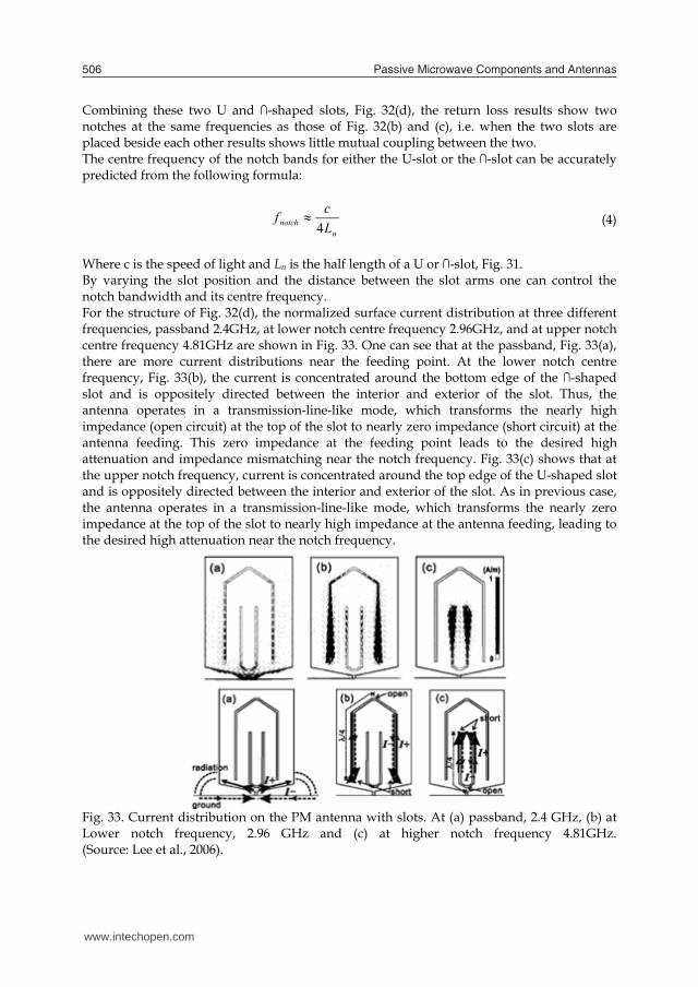
Where c is the speed of light and Ln is the half length of a U or ∩-slot, Fig. 31. By varying the slot position and the distance between the slot arms one can control the notch bandwidth and its centre frequency. For the structure of Fig. 32(d), the normalized surface current distribution at three different frequencies, passband 2.4GHz, at lower notch centre frequency 2.96GHz, and at upper notch centre frequency 4.81GHz are shown in Fig. 33. One can see that at the passband, Fig. 33(a), there are more current distributions near the feeding point. At the lower notch centre frequency, Fig. 33(b), the current is concentrated around the bottom edge of the ∩-shaped slot and is oppositely directed between the interior and exterior of the slot. Thus, the antenna operates in a transmission-line-like mode, which transforms the nearly high impedance (open circuit) at the top of the slot to nearly zero impedance (short circuit) at the antenna feeding. This zero impedance at the feeding point leads to the desired high attenuation and impedance mismatching near the notch frequency. Fig. 33(c) shows that at the upper notch frequency, current is concentrated around the top edge of the U-shaped slot and is oppositely directed between the interior and exterior of the slot. As in previous case, the antenna operates in a transmission-line-like mode, which transforms the nearly zero impedance at the top of the slot to nearly high impedance at the antenna feeding, leading to the desired high attenuation near the notch frequency.
Fig. 33. Current distribution on the PM antenna with slots. At (a) passband, 2.4 GHz, (b) at Lower notch frequency, 2.96 GHz and (c) at higher notch frequency 4.81GHz. (Source: Lee et al., 2006).
Fig. 34. Conceptual equivalent-circuit model for antenna with U and ∩-shaped slots. At (a) passband (b) first notch frequency, (c) second notch frequency. (Source: Lee et al., 2006).
Fig. 34 shows the conceptual equivalent-circuit model for the antenna, that includes a series stub, a shunt stub, and antenna resistance Ra. At passband the stubs are non operational and radiation takes place. The stubs are a short-circuit stub with L1 = 15.6 mm and an open-circuit stub with L2=24.6 mm. When L2 is equal to λ/4 in Fig. 34(b), at 2.96 GHz, the input impedance at the feeding point is zero (short circuit). Also, when L1 is equal to λ/4 in Fig. 34(c), at 4.78 GHz, the input impedance at the feeding point is high (open circuit) due to the quarter-wave transformer. In these two cases, destructive interference for the excited surface currents in the antenna will occur, which causes the antenna to be non responsive at those frequencies.
9.2. Simple horizontal slots Simple horizontal slots cut from the edges of the wideband monopole planar antenna can also create notch bands (Rahmati & Hassani, 2009). Such slots cut from the edges of the monopole antenna are easier to create as compared to U-slots cut from the centre of the antenna. Fig. 35 shows the antenna structure where a copper planar element of thickness, 0.2 mm, size 22mm 25 mm and beveling angle of 17(or hb=4mm), is mounted 0.5 mm over the circular ground plane of radius 40mm. Through placement of single horizontal slot, a single and a double pair of horizontal symmetrical slots placed on the edges of the monopole antenna single and double tunable notch characteristics can be obtained.
Fig. 35. Geometry of the planar monopole antenna with simple horizontal cuts. (Source: Rahmati & Hassani, 2009).
www.intechopen.com

Wideband planar plate monopole antenna 507
Combining these two U and ∩-shaped slots, Fig. 32(d), the return loss results show two notches at the same frequencies as those of Fig. 32(b) and (c), i.e. when the two slots are placed beside each other results shows little mutual coupling between the two. The centre frequency of the notch bands for either the U-slot or the ∩-slot can be accurately predicted from the following formula:
nnotch L
cf4
(4)
Where c is the speed of light and Ln is the half length of a U or ∩-slot, Fig. 31. By varying the slot position and the distance between the slot arms one can control the notch bandwidth and its centre frequency. For the structure of Fig. 32(d), the normalized surface current distribution at three different frequencies, passband 2.4GHz, at lower notch centre frequency 2.96GHz, and at upper notch centre frequency 4.81GHz are shown in Fig. 33. One can see that at the passband, Fig. 33(a), there are more current distributions near the feeding point. At the lower notch centre frequency, Fig. 33(b), the current is concentrated around the bottom edge of the ∩-shaped slot and is oppositely directed between the interior and exterior of the slot. Thus, the antenna operates in a transmission-line-like mode, which transforms the nearly high impedance (open circuit) at the top of the slot to nearly zero impedance (short circuit) at the antenna feeding. This zero impedance at the feeding point leads to the desired high attenuation and impedance mismatching near the notch frequency. Fig. 33(c) shows that at the upper notch frequency, current is concentrated around the top edge of the U-shaped slot and is oppositely directed between the interior and exterior of the slot. As in previous case, the antenna operates in a transmission-line-like mode, which transforms the nearly zero impedance at the top of the slot to nearly high impedance at the antenna feeding, leading to the desired high attenuation near the notch frequency.
Fig. 33. Current distribution on the PM antenna with slots. At (a) passband, 2.4 GHz, (b) at Lower notch frequency, 2.96 GHz and (c) at higher notch frequency 4.81GHz. (Source: Lee et al., 2006).
Fig. 34. Conceptual equivalent-circuit model for antenna with U and ∩-shaped slots. At (a) passband (b) first notch frequency, (c) second notch frequency. (Source: Lee et al., 2006).
Fig. 34 shows the conceptual equivalent-circuit model for the antenna, that includes a series stub, a shunt stub, and antenna resistance Ra. At passband the stubs are non operational and radiation takes place. The stubs are a short-circuit stub with L1 = 15.6 mm and an open-circuit stub with L2=24.6 mm. When L2 is equal to λ/4 in Fig. 34(b), at 2.96 GHz, the input impedance at the feeding point is zero (short circuit). Also, when L1 is equal to λ/4 in Fig. 34(c), at 4.78 GHz, the input impedance at the feeding point is high (open circuit) due to the quarter-wave transformer. In these two cases, destructive interference for the excited surface currents in the antenna will occur, which causes the antenna to be non responsive at those frequencies.
9.2. Simple horizontal slots Simple horizontal slots cut from the edges of the wideband monopole planar antenna can also create notch bands (Rahmati & Hassani, 2009). Such slots cut from the edges of the monopole antenna are easier to create as compared to U-slots cut from the centre of the antenna. Fig. 35 shows the antenna structure where a copper planar element of thickness, 0.2 mm, size 22mm 25 mm and beveling angle of 17(or hb=4mm), is mounted 0.5 mm over the circular ground plane of radius 40mm. Through placement of single horizontal slot, a single and a double pair of horizontal symmetrical slots placed on the edges of the monopole antenna single and double tunable notch characteristics can be obtained.
Fig. 35. Geometry of the planar monopole antenna with simple horizontal cuts. (Source: Rahmati & Hassani, 2009).
www.intechopen.com

Passive Microwave Components and Antennas508
The effect that a single horizontal slot cut from one edge of a monopole antenna has on the antenna are shown in Fig. 36. There are three parameters, Ls, Ws and h that affect the notch band. Fig. 36(a) shows the return loss of the antenna for various position of the slot, h. The results show that when h is varied from 11mm to 20mm the notch bandwidth decreases from 20% to 4%, the return loss of the notch at centre frequency decreases and only a small shift in the notch centre frequency takes place. Fig. 36(b) shows the return loss as slot length, Ls, is varied. The results show that with an increase in Ls, the notch centre frequency decreases with an improved notch behavior. Although not shown, results on variation of slot width, Ws, shows that as Ws is increased, the notched bandwidth increases from 9% to 20% and only a small shift in notch centre frequency takes place. From these results, the centre frequency of the notch can be obtained through the following approximate formula:
5.04notch hL
cfs (5)
where c is the speed of light. It can be seen that the notch frequency is controlled mostly by the slot length Ls.
Fig. 36. Return loss of a single slot for various slot (a) Position, h (Ls = 11mm, Ws = 0.5mm) and (b) Length, Ls (h = 20 mm, Ws = 0.5 mm). (Source: Rahmati & Hassani, 2009). The antenna structure with only a slot at one edge may not produce a symmetric radiation pattern. Thus, the case of a pair of symmetrical slots cut from the sides of the antenna is considered. Fig. 37(a) shows the return loss of the antenna for various position of the slot, h. From this result it is seen that the pair of symmetrical slots results in a wider notch bandwidth as compared to that of single slot. When h is varied from 11mm to 20mm the notch bandwidth reduces from 55% to 12% and a very small shift in notch centre frequency takes place. The single pair of symmetrical slots can be modeled as two resonances connected in series to the initial monopole antenna. Slots of equal length result in equal resonant frequency and higher notch bandwidth. The effect of various slot length, Ls, is shown in Fig. 37(b). It is seen that the length of the slot determines the centre frequency of the notched band. As Ls is increased the notch centre frequency shifts toward the lower frequency with an increase in return loss level. Results on variation of Ws, similar to the previous single slot case, shows that as Ws is varied from 0.3mm to 1mm, the notch bandwidth increases from 9% to 20% and only a small shift in
notch centre frequency takes place. From the results of Fig. 37 it is seen that the centre frequency of the notch is more dependent on the length and position of the slot while the slot position also affects the bandwidth of the notch. From these results one can state that for slot position h <16mm the centre frequency of the notch can be obtained through the following approximate formula:
4notch hL
cfs (6)
while for h>16mm, the effect of slot position becomes less, thus the formula in equation (5) would be more suitable.
Fig. 37. Return loss of a single pair of symmetric slots for various slot (a) height, h. (Ls = 11 mm, Ws = 0.5 mm) and (b) length, Ls. (h = 16 mm, Ws = 0.5 mm). (Source: Rahmati & Hassani, 2009).
Fig. 38 shows the normalized surface current distribution over the planar monopole antenna for the single and for a pair of slots at various frequencies. In Fig. 38(a) and (c), where the antenna operates at pass band frequencies 3.5 and 13GHz, there are more current distributions near the feeding point(i.e. slot does not resonate and has little effect). At notch frequency, 5.7 GHz, as shown in Fig. 38(b), current is concentrated around the edge of the slot while there is almost no current at the feeding point. The high concentration of current around the slot can be represented as a short circuited stub. The edge loaded slot monopole antenna can then be modeled as a short circuited stub in series with the unloaded monopole radiation resistance, R, Fig. 38(d, e). For the case of single pair of symmetric slots, there would be two short circuited stubs connected in series with R. At notch frequency, the slot is almost λ/4 and thus transforms short circuit at the slot to open circuit at the antenna feeding point. This leads to the desired high attenuation and impedance mismatching around the notch frequency.
www.intechopen.com

Wideband planar plate monopole antenna 509
The effect that a single horizontal slot cut from one edge of a monopole antenna has on the antenna are shown in Fig. 36. There are three parameters, Ls, Ws and h that affect the notch band. Fig. 36(a) shows the return loss of the antenna for various position of the slot, h. The results show that when h is varied from 11mm to 20mm the notch bandwidth decreases from 20% to 4%, the return loss of the notch at centre frequency decreases and only a small shift in the notch centre frequency takes place. Fig. 36(b) shows the return loss as slot length, Ls, is varied. The results show that with an increase in Ls, the notch centre frequency decreases with an improved notch behavior. Although not shown, results on variation of slot width, Ws, shows that as Ws is increased, the notched bandwidth increases from 9% to 20% and only a small shift in notch centre frequency takes place. From these results, the centre frequency of the notch can be obtained through the following approximate formula:
5.04notch hL
cfs (5)
where c is the speed of light. It can be seen that the notch frequency is controlled mostly by the slot length Ls.
Fig. 36. Return loss of a single slot for various slot (a) Position, h (Ls = 11mm, Ws = 0.5mm) and (b) Length, Ls (h = 20 mm, Ws = 0.5 mm). (Source: Rahmati & Hassani, 2009). The antenna structure with only a slot at one edge may not produce a symmetric radiation pattern. Thus, the case of a pair of symmetrical slots cut from the sides of the antenna is considered. Fig. 37(a) shows the return loss of the antenna for various position of the slot, h. From this result it is seen that the pair of symmetrical slots results in a wider notch bandwidth as compared to that of single slot. When h is varied from 11mm to 20mm the notch bandwidth reduces from 55% to 12% and a very small shift in notch centre frequency takes place. The single pair of symmetrical slots can be modeled as two resonances connected in series to the initial monopole antenna. Slots of equal length result in equal resonant frequency and higher notch bandwidth. The effect of various slot length, Ls, is shown in Fig. 37(b). It is seen that the length of the slot determines the centre frequency of the notched band. As Ls is increased the notch centre frequency shifts toward the lower frequency with an increase in return loss level. Results on variation of Ws, similar to the previous single slot case, shows that as Ws is varied from 0.3mm to 1mm, the notch bandwidth increases from 9% to 20% and only a small shift in
notch centre frequency takes place. From the results of Fig. 37 it is seen that the centre frequency of the notch is more dependent on the length and position of the slot while the slot position also affects the bandwidth of the notch. From these results one can state that for slot position h <16mm the centre frequency of the notch can be obtained through the following approximate formula:
4notch hL
cfs (6)
while for h>16mm, the effect of slot position becomes less, thus the formula in equation (5) would be more suitable.
Fig. 37. Return loss of a single pair of symmetric slots for various slot (a) height, h. (Ls = 11 mm, Ws = 0.5 mm) and (b) length, Ls. (h = 16 mm, Ws = 0.5 mm). (Source: Rahmati & Hassani, 2009).
Fig. 38 shows the normalized surface current distribution over the planar monopole antenna for the single and for a pair of slots at various frequencies. In Fig. 38(a) and (c), where the antenna operates at pass band frequencies 3.5 and 13GHz, there are more current distributions near the feeding point(i.e. slot does not resonate and has little effect). At notch frequency, 5.7 GHz, as shown in Fig. 38(b), current is concentrated around the edge of the slot while there is almost no current at the feeding point. The high concentration of current around the slot can be represented as a short circuited stub. The edge loaded slot monopole antenna can then be modeled as a short circuited stub in series with the unloaded monopole radiation resistance, R, Fig. 38(d, e). For the case of single pair of symmetric slots, there would be two short circuited stubs connected in series with R. At notch frequency, the slot is almost λ/4 and thus transforms short circuit at the slot to open circuit at the antenna feeding point. This leads to the desired high attenuation and impedance mismatching around the notch frequency.
www.intechopen.com

Passive Microwave Components and Antennas510
Fig. 38. Surface current of antenna with a pair of slots, at the (a) pass band 3.5 GHz, (b) notch frequency 5.7 GHz, (c) pass band 13 GHz. The equivalent-circuit model for slot loaded planar monopole antenna at (d), pass band frequency (e) notch frequency. (Source: Rahmati & Hassani, 2009). To create multiple notch bands multiple horizontal slots placed on top of each other are required. Here, the case of the planar monopole antenna with two pairs of horizontal symmetrical slots is presented. The presence of the second pair of slots creates an extra resonance (notch), whose centre frequency is dependent on the parameters of this pair of slots. In the cases studied the dimensions of the upper pair of slots are kept fixed while those of the lower pair of slots are varied. Fig. 39(a) shows the return loss results for various lengths of the lower pair of slots, Ls2. It is seen that increasing Ls2 towards Ls1 the centre frequency of the second resonance approaches that of the first, thus increasing the bandwidth of the notch. Fig. 39(b) shows the return loss for various heights of the lower pair of slots. From Fig. 35, beveling height, hb is 4mm, thus, h2=3mm is for a slot which is placed in the beveling region of the monopole antenna. As the length of this slot in such a region is small, the upper centre frequency would be quite high. As the slot is moved up from this region (i.e. h2 >4mm) there is not much change in upper centre frequency while its return loss level reduces. Similar to the two previous cases, as the width of the slot, Ws2, is increased the bandwidth of the upper resonance increases while its centre frequency changes slightly.
Fig. 39. Return loss of two pairs of symmetrical slots for various lower pair of slots (a) lengths Ls2, (h1= 20 mm, Ls1= 11 mm, h2 = 8 mm, Ws = 0.5 mm) and (b) heights h2, (h1 = 20 mm, Ls1 = 11 mm, Ls2 = 5 mm, Ws = 0.5 mm). (Source: Rahmati & Hassani, 2009).
10. References
Agrawall, P. A.; Kumar, G. & Ray, K. (1998). Wideband planar monopole antennas, IEEETransactions on Antennas Propagation, vol. 46, no. 2, Feb. 1998, pp. 294–295.
Ammann, M. J. (1999). Square Planar Monopole Antenna, Proc. IEE Nat. Antennas Propag. Conf., York, U.K., IEE Publication no. 461, 1999, pp. 37-40.
Ammann, M. J. (2001). Control of the impedance bandwidth of wideband planar monopole antennas using a beveling technique. Microwave and Optical Tech. Letters, vol. 30, no. 4, August 2001, pp. 229-232.
Ammann, M. J. & Chen, Z. N. (2003a). Wideband Monopole Antennas for Multi-Band Wireless Systems, IEEE Antennas and Propagation Magazine, vol. 45, no. 2, April 2003, pp. 146-150.
Ammann, M. J. & Chen, Z. N. (2003b). A Wide-Band Shorted Planar Monopole With Bevel, IEEE Transactions on Antennas and Propagation, vol. 51, no. 4, April 2003, pp. 901-903.
Antonino-Daviu, E.; Cabedo-Fabre´s, M.; Ferrando-Bataller, M. & Valero-Nogueira, A. (2003). Wideband double-fed planar monopole antennas, Electronics Letters, vol. 39, no. 23, 13th Nov. 2003, pp. 1635-1636.
Balanis, C. A. (1982). Antenna Theory: Analysis and Design, New York, Harper and Row, 1982.
Dubost, G. & Zisler, S. (1976). Antennas a Large Bande, Masson, Paris, New York, 1976, pp. 128–129.
Harrington, R.F. & Mautz, J. R. (1971). Theory of characteristic modes for conducting bodies, IEEE Transactions on Antennas Propagation, vol. 19, no. 5, Sept. 1971, pp. 622–628.
Lee, E.; Hall, P. S. & Gardner, P. (1999). Compact wideband planar monopole Antenna, Electronics Letters, vol. 35, no. 25, 9th Dec. 1999, pp. 2157-2158.
Lee, Wang-Sang; Lim, Won-Gyu & Yu, Jong-Won (2005). Multiple Band-Notched Planar Monopole Antenna for Multiband Wireless Systems, IEEE Microwave and Wireless Components Letters, vol. 15, no. 9, Sept. 2005, pp. 576-578.
Lee, Wang-Sang; Kim, Dong-Zo; Kim, Ki-Jin & Yu, Jong-Won (2006). Wideband Planar Monopole Antennas With Dual Band-Notched Characteristics, IEEE Transaction on Microwave Theory and Techniques, vol. 54, no. 6, June 2006, pp. 2800-2806.
Mazinani, S. M. & Hassani, H.R. (2009a). A Novel Broadband Plate-Loaded Planar Monopole Antenna, IEEE Antennas and Wireless Propagation Letters, vol. 8, 2009, pp. 1123-1126.
Mazinani, S. M. & Hassani, H.R. (2009b). A wideband internal plate loaded planar monopole antenna for mobile handset, J. of Electromagn. Waves and Appl., vol. 23, 2009, pp. 1273–1282.
Rahmati, B. & Hassani, H.R. (2009). Frequency notched wide band planar monopole antennas, Progress In Electromagnetics Research C, vol. 9, 2009, pp. 131-143.
Valderas, D.; Legarda, J.; Gutiérrez, I. & Sancho, J. I. (2006). Design of UWB Folded-Plate Monopole Antennas Based on TLM, IEEE Transactions on Antennas & Propagation, vol. 54, no.
6, June 2006, pp. 1676-1687. Wong, Kin-Lu; Wu, Chih-Hsien & Su, Saou-Wen (Stephen) (2005). UltrawideBand Square
Planar Metal-Plate Monopole Antenna With a Trident-Shaped Feeding Strip, IEEE Transactions on Antennas & Propagation, vol. 53, no. 4, April 2005, pp. 1262-1269.
www.intechopen.com

Wideband planar plate monopole antenna 511
Fig. 38. Surface current of antenna with a pair of slots, at the (a) pass band 3.5 GHz, (b) notch frequency 5.7 GHz, (c) pass band 13 GHz. The equivalent-circuit model for slot loaded planar monopole antenna at (d), pass band frequency (e) notch frequency. (Source: Rahmati & Hassani, 2009). To create multiple notch bands multiple horizontal slots placed on top of each other are required. Here, the case of the planar monopole antenna with two pairs of horizontal symmetrical slots is presented. The presence of the second pair of slots creates an extra resonance (notch), whose centre frequency is dependent on the parameters of this pair of slots. In the cases studied the dimensions of the upper pair of slots are kept fixed while those of the lower pair of slots are varied. Fig. 39(a) shows the return loss results for various lengths of the lower pair of slots, Ls2. It is seen that increasing Ls2 towards Ls1 the centre frequency of the second resonance approaches that of the first, thus increasing the bandwidth of the notch. Fig. 39(b) shows the return loss for various heights of the lower pair of slots. From Fig. 35, beveling height, hb is 4mm, thus, h2=3mm is for a slot which is placed in the beveling region of the monopole antenna. As the length of this slot in such a region is small, the upper centre frequency would be quite high. As the slot is moved up from this region (i.e. h2 >4mm) there is not much change in upper centre frequency while its return loss level reduces. Similar to the two previous cases, as the width of the slot, Ws2, is increased the bandwidth of the upper resonance increases while its centre frequency changes slightly.
Fig. 39. Return loss of two pairs of symmetrical slots for various lower pair of slots (a) lengths Ls2, (h1= 20 mm, Ls1= 11 mm, h2 = 8 mm, Ws = 0.5 mm) and (b) heights h2, (h1 = 20 mm, Ls1 = 11 mm, Ls2 = 5 mm, Ws = 0.5 mm). (Source: Rahmati & Hassani, 2009).
10. References
Agrawall, P. A.; Kumar, G. & Ray, K. (1998). Wideband planar monopole antennas, IEEETransactions on Antennas Propagation, vol. 46, no. 2, Feb. 1998, pp. 294–295.
Ammann, M. J. (1999). Square Planar Monopole Antenna, Proc. IEE Nat. Antennas Propag. Conf., York, U.K., IEE Publication no. 461, 1999, pp. 37-40.
Ammann, M. J. (2001). Control of the impedance bandwidth of wideband planar monopole antennas using a beveling technique. Microwave and Optical Tech. Letters, vol. 30, no. 4, August 2001, pp. 229-232.
Ammann, M. J. & Chen, Z. N. (2003a). Wideband Monopole Antennas for Multi-Band Wireless Systems, IEEE Antennas and Propagation Magazine, vol. 45, no. 2, April 2003, pp. 146-150.
Ammann, M. J. & Chen, Z. N. (2003b). A Wide-Band Shorted Planar Monopole With Bevel, IEEE Transactions on Antennas and Propagation, vol. 51, no. 4, April 2003, pp. 901-903.
Antonino-Daviu, E.; Cabedo-Fabre´s, M.; Ferrando-Bataller, M. & Valero-Nogueira, A. (2003). Wideband double-fed planar monopole antennas, Electronics Letters, vol. 39, no. 23, 13th Nov. 2003, pp. 1635-1636.
Balanis, C. A. (1982). Antenna Theory: Analysis and Design, New York, Harper and Row, 1982.
Dubost, G. & Zisler, S. (1976). Antennas a Large Bande, Masson, Paris, New York, 1976, pp. 128–129.
Harrington, R.F. & Mautz, J. R. (1971). Theory of characteristic modes for conducting bodies, IEEE Transactions on Antennas Propagation, vol. 19, no. 5, Sept. 1971, pp. 622–628.
Lee, E.; Hall, P. S. & Gardner, P. (1999). Compact wideband planar monopole Antenna, Electronics Letters, vol. 35, no. 25, 9th Dec. 1999, pp. 2157-2158.
Lee, Wang-Sang; Lim, Won-Gyu & Yu, Jong-Won (2005). Multiple Band-Notched Planar Monopole Antenna for Multiband Wireless Systems, IEEE Microwave and Wireless Components Letters, vol. 15, no. 9, Sept. 2005, pp. 576-578.
Lee, Wang-Sang; Kim, Dong-Zo; Kim, Ki-Jin & Yu, Jong-Won (2006). Wideband Planar Monopole Antennas With Dual Band-Notched Characteristics, IEEE Transaction on Microwave Theory and Techniques, vol. 54, no. 6, June 2006, pp. 2800-2806.
Mazinani, S. M. & Hassani, H.R. (2009a). A Novel Broadband Plate-Loaded Planar Monopole Antenna, IEEE Antennas and Wireless Propagation Letters, vol. 8, 2009, pp. 1123-1126.
Mazinani, S. M. & Hassani, H.R. (2009b). A wideband internal plate loaded planar monopole antenna for mobile handset, J. of Electromagn. Waves and Appl., vol. 23, 2009, pp. 1273–1282.
Rahmati, B. & Hassani, H.R. (2009). Frequency notched wide band planar monopole antennas, Progress In Electromagnetics Research C, vol. 9, 2009, pp. 131-143.
Valderas, D.; Legarda, J.; Gutiérrez, I. & Sancho, J. I. (2006). Design of UWB Folded-Plate Monopole Antennas Based on TLM, IEEE Transactions on Antennas & Propagation, vol. 54, no.
6, June 2006, pp. 1676-1687. Wong, Kin-Lu; Wu, Chih-Hsien & Su, Saou-Wen (Stephen) (2005). UltrawideBand Square
Planar Metal-Plate Monopole Antenna With a Trident-Shaped Feeding Strip, IEEE Transactions on Antennas & Propagation, vol. 53, no. 4, April 2005, pp. 1262-1269.
www.intechopen.com

Passive Microwave Components and Antennas512
www.intechopen.com

Passive Microwave Components and AntennasEdited by Vitaliy Zhurbenko
ISBN 978-953-307-083-4Hard cover, 556 pagesPublisher InTechPublished online 01, April, 2010Published in print edition April, 2010
InTech EuropeUniversity Campus STeP Ri Slavka Krautzeka 83/A 51000 Rijeka, Croatia Phone: +385 (51) 770 447 Fax: +385 (51) 686 166www.intechopen.com
InTech ChinaUnit 405, Office Block, Hotel Equatorial Shanghai No.65, Yan An Road (West), Shanghai, 200040, China
Phone: +86-21-62489820 Fax: +86-21-62489821
Modelling and computations in electromagnetics is a quite fast-growing research area. The recent interest inthis field is caused by the increased demand for designing complex microwave components, modelingelectromagnetic materials, and rapid increase in computational power for calculation of complexelectromagnetic problems. The first part of this book is devoted to the advances in the analysis techniquessuch as method of moments, finite-difference time- domain method, boundary perturbation theory, Fourieranalysis, mode-matching method, and analysis based on circuit theory. These techniques are considered withregard to several challenging technological applications such as those related to electrically large devices,scattering in layered structures, photonic crystals, and artificial materials. The second part of the book dealswith waveguides, transmission lines and transitions. This includes microstrip lines (MSL), slot waveguides,substrate integrated waveguides (SIW), vertical transmission lines in multilayer media as well as MSL to SIWand MSL to slot line transitions.
How to referenceIn order to correctly reference this scholarly work, feel free to copy and paste the following:
H. R. Hassani and S. M. Mazinani (2010). Wideband Planar Plate Monopole Antenna, Passive MicrowaveComponents and Antennas, Vitaliy Zhurbenko (Ed.), ISBN: 978-953-307-083-4, InTech, Available from:http://www.intechopen.com/books/passive-microwave-components-and-antennas/wideband-planar-plate-monopole-antenna