Embed Size (px)
Citation preview
International Research Journal of Engineering and Technology (IRJET) e-ISSN: 2395-0056
Volume: 04 Issue: 11 | Nov -2017 www.irjet.net p-ISSN: 2395-0072
© 2017, IRJET | Impact Factor value: 6.171 | ISO 9001:2008 Certified Journal | Page 1978
Design of an Elliptical Planar Monopole Antenna for Using in
Radar-Based and Ultra-Wideband Microwave Imaging System
Ali Recai Celik1, Muhammed Bahaddin Kurt2, Selcuk Helhel3
1Ph.D. Student, Department of Electrical and Electronics Engineering, Dicle University, Diyarbakir, Turkey 2Assistant Professor, Department of Electrical and Electronics Engineering, Dicle University, Diyarbakir, Turkey 3Associate Professor, Department of Electrical and Electronics Engineering, Akdeniz University, Antalya, Turkey
---------------------------------------------------------------------***---------------------------------------------------------------------Abstract – Microwave imaging technology has attracted many interests nowadays. This imaging system has been used in a variety of applications such as: non-destructive testing and evaluation, through-the-wall imaging, concealed weapon detection at security check points, structural health monitoring and medical imaging. There are several microwave imaging methods. One of these is radar-based ultra-wideband technique. A key component of this technique is the sensor that is used to radiate and receive the ultra-wideband pulses. This system requires ultra-wideband, compact, stable and directive antennas as their sensors. Planar monopole antennas can provide these properties in the case of proper design and optimization. In this study, an elliptical planar monopole antenna with parabolic shaped ground structure is developed by using simulation program. Return loss and radiation pattern results are shown and discussed briefly in the paper. Results show that the designed antenna has broad frequency band and it has stable and directional radiation patterns. Therefore we say that it can be used for radar-based UWB MI system. Key Words: Microwave imaging, Ultra-wideband system, Planar monopole antenna, Directional antenna
1. INTRODUCTION
Microwave imaging (MI) methods have shown excellent capabilities in various fields such as civil engineering, nondestructive testing, industrial applications, and have in recent decades experienced strong growth as a research topic in biomedical diagnostics. MI is done mainly in three category as passive, hybrid and active systems [1].
The passive method involves microwave radiometry uses radiometers to obtain the temperature differences in the breast as temperature rises in the presence of tumor than with normal breast tissue [2]. The hybrid methods use microwave energy to heat tumors and they expand and generate pressure waves which are detected by ultrasound transducers [3]. The active methods involve illuminating the breast with microwaves and then measuring transmitted or backscattered signals. Active MI can be classified as microwave tomography, microwave microscopy and ultra-wideband (UWB) radar technique.
In general, The Federal Communication Commission (FCC) in the USA has allocated a frequency band from 3.1
GHz to 10.6 GHz for ultra-wideband (UWB) technology [4]. Therefore, UWB technology has become very popular in different areas. One of these applications of this technology is UWB MI technique for several aims. MI technology has attracted many interests nowadays. This imaging system has been used in a variety of applications such as: non-destructive testing and evaluation, through-the-wall imaging, concealed weapon detection at security check points, structural health monitoring and medical imaging.
MI systems have in recent decades experienced strong growth as a research topic in biomedical diagnostics, particularly breast tumor detection [5]. MI methods use nonionizing radiation which is safer than ionizing radiation. Low illumination power levels used in microwave imaging also make regular screening possible. Another advantage of microwave imaging that is low cost.
2. MICROWAVE IMAGING TECHNIQUES
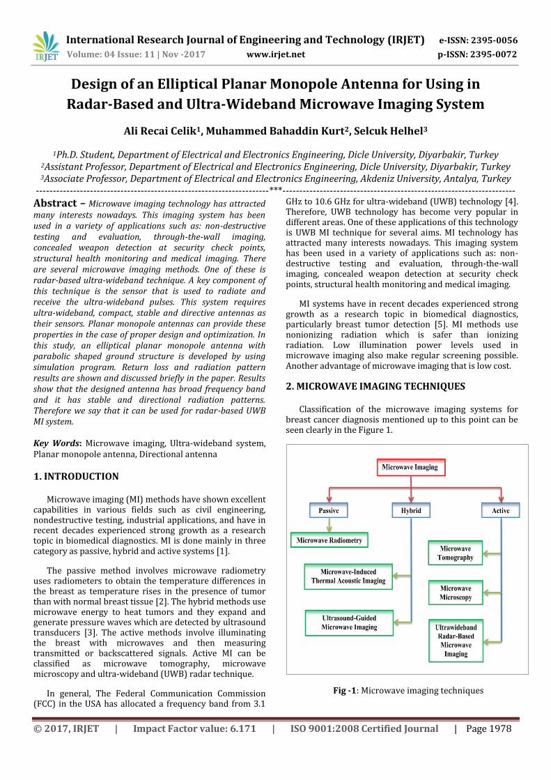
Classification of the microwave imaging systems for breast cancer diagnosis mentioned up to this point can be seen clearly in the Figure 1.
Fig -1: Microwave imaging techniques
International Research Journal of Engineering and Technology (IRJET) e-ISSN: 2395-0056
Volume: 04 Issue: 11 | Nov -2017 www.irjet.net p-ISSN: 2395-0072
© 2017, IRJET | Impact Factor value: 6.171 | ISO 9001:2008 Certified Journal | Page 1979
2.1 Radar-Based and UWB MI System
In UWB applications, it is desirable for impedance bandwidth to be at least 50% to cover the lower UWB band of 3.1–5 GHz or the upper band of 6–10.6 GHz or 110% to cover the entire UWB band of 3.1–10.6 GHz [6]. UWB radar imaging, uses an UWB pulse which involves low to high frequencies. The lower frequency band provides sufficient depth of penetration while the higher frequency band ensures the adequate resolution of the creating images. Hence, both the deeply buried and small size tumor can be detected based on the lower and higher frequencies of the UWB bands [7].
This method has been increasingly recommended as a regular examination and detection tool for early breast cancer detection but it is under research and investigation stage till today [8]. A key component of the system is the antenna that is used to radiate and receive the ultra-wideband pulses. The designed antenna for radar-based UWB MI system should radiate UWB signals and have small size. Good impedance matching, high directivity and narrow beamwidth are desirable properties for the antenna.
For microwave imaging, researchers are interested in the 1-11 GHz frequency range because it appears to balance the conflicting demands of better spatial resolution (higher frequencies) and better penetration depth (lower frequencies) [9].
Recent researches are on UWB antenna is planar technologies as they are more practical in term of manufacturing and integration with the entire system. There are several compact UWB antennas are proposed in planar technology but they exhibit omini directional radiation property [10-13]. However, in the radar-based microwave imaging system, antenna's Half Power Beamwidth (HPBW) is one of the main parameters determining the resolution; finer details can be resolved by using a narrower beam. Planar and printed monopole antennas are the good candidates for use in UWB technology because of their wide impedance bandwidth. If some modifications make to achieve it directional, then these antennas is valid for microwave imaging, too.
3. PLANAR MONOPOLE ANTENNAS
The planar monopole antenna can be viewed as a special case of microstrip antenna configuration, wherein the backing ground plane is located at infinity [14]. A patch is fabricated on dielectric substrate. Beyond the substrate it can be assumed that a very thick air dielectric substrate exists. It makes a microstrip antenna configuration on a thick substrate with closer to unity, which yields large bandwidth. Planar monopole antennas can be seen as a vertical monopole antenna. A monopole antenna usually consists of a vertical cylindrical wire mounted over the ground plane, whose bandwidth increases with increase in its diameter [15].
Because of these explained reasons, the planar monopole antennas give very large impedance bandwidth with reasonably good radiation pattern in azimuthal plane.
Various regular shaped printed monopole antennas such as printed square monopole, printed rectangular monopole, printed hexagonal monopole, printed triangular monopole, printed circular monopole, and printed elliptical monopole antenna use in UWB applications. However, it is not sufficient for the antenna to be used in the MI system to have UWB but it should have also a stable and high directional pattern and low HPBW which provides the high resolution capabilities for the antenna to recognize two adjacent radiating sources or radar targets through worked frequency band [16].
For this aim, a directional elliptical monopole UWB antenna with L-shaped ground plane is designed. Detailed design process is given in the next Section.
3.1 UWB and Directive Elliptical Monopole Antenna
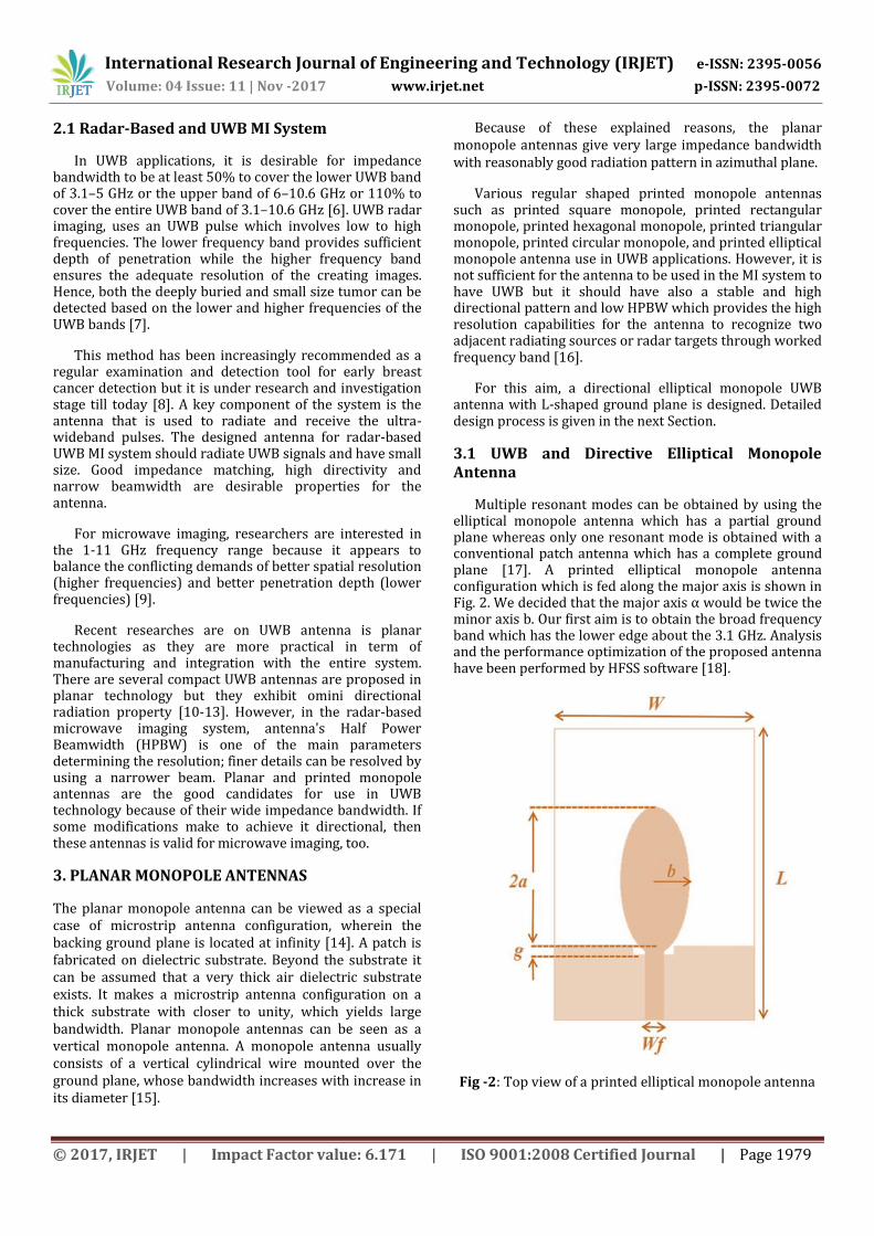
Multiple resonant modes can be obtained by using the elliptical monopole antenna which has a partial ground plane whereas only one resonant mode is obtained with a conventional patch antenna which has a complete ground plane [17]. A printed elliptical monopole antenna configuration which is fed along the major axis is shown in Fig. 2. We decided that the major axis α would be twice the minor axis b. Our first aim is to obtain the broad frequency band which has the lower edge about the 3.1 GHz. Analysis and the performance optimization of the proposed antenna have been performed by HFSS software [18].
Fig -2: Top view of a printed elliptical monopole antenna
International Research Journal of Engineering and Technology (IRJET) e-ISSN: 2395-0056
Volume: 04 Issue: 11 | Nov -2017 www.irjet.net p-ISSN: 2395-0072
© 2017, IRJET | Impact Factor value: 6.171 | ISO 9001:2008 Certified Journal | Page 1980
To estimate the lower band-edge frequency of printed monopole antennas, the standard formulation is given in [19,20] as below:
7.
*( r p) k+ z
where α, r b/4, α b and p 1mm, α and b are the major and minor axis radius, respectively. The empirical value of k was reported as 1.15 for a dielectric substrate with =4.4 and h=0.159 cm in [21,22]. Therefore, for our study we take the k as 1.15, too.
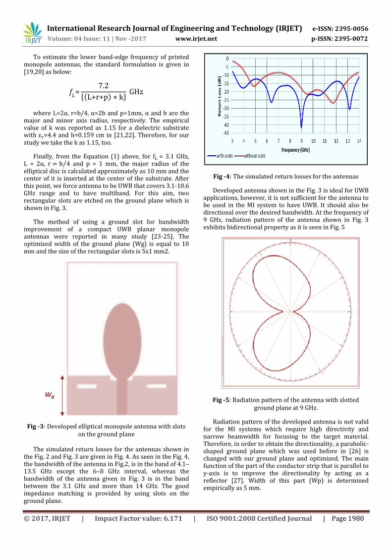
Finally, from the Equation (1) above, for = 3.1 GHz, α, ⁄ and p = 1 mm, the major radius of the elliptical disc is calculated approximately as 10 mm and the center of it is inserted at the center of the substrate. After this point, we force antenna to be UWB that covers 3.1-10.6 GHz range and to have multiband. For this aim, two rectangular slots are etched on the ground plane which is shown in Fig. 3.
The method of using a ground slot for bandwidth improvement of a compact UWB planar monopole antennas were reported in many study [23-25]. The optimized width of the ground plane (Wg) is equal to 10 mm and the size of the rectangular slots is 5x1 mm2.
Fig -3: Developed elliptical monopole antenna with slots on the ground plane
The simulated return losses for the antennas shown in
the Fig. 2 and Fig. 3 are given in Fig. 4. As seen in the Fig. 4, the bandwidth of the antenna in Fig.2, is in the band of 4.1–13.5 GHz except the 6–8 GHz interval, whereas the bandwidth of the antenna given in Fig. 3 is in the band between the 3.1 GHz and more than 14 GHz. The good impedance matching is provided by using slots on the ground plane.
Fig -4: The simulated return losses for the antennas
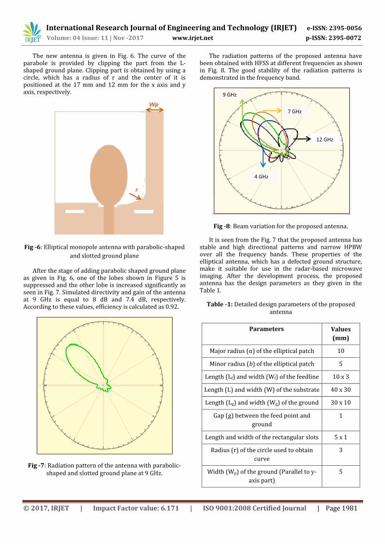
Developed antenna shown in the Fig. 3 is ideal for UWB applications, however, it is not sufficient for the antenna to be used in the MI system to have UWB. It should also be directional over the desired bandwidth. At the frequency of 9 GHz, radiation pattern of the antenna shown in Fig. 3 exhibits bidirectional property as it is seen in Fig. 5
Fig -5: Radiation pattern of the antenna with slotted ground plane at 9 GHz.
Radiation pattern of the developed antenna is not valid for the MI systems which require high directivity and narrow beamwidth for focusing to the target material. Therefore, in order to obtain the directionality, a parabolic-shaped ground plane which was used before in [26] is changed with our ground plane and optimized. The main function of the part of the conductor strip that is parallel to y-axis is to improve the directionality by acting as a reflector [27]. Width of this part (Wp) is determined empirically as 5 mm.
International Research Journal of Engineering and Technology (IRJET) e-ISSN: 2395-0056
Volume: 04 Issue: 11 | Nov -2017 www.irjet.net p-ISSN: 2395-0072
© 2017, IRJET | Impact Factor value: 6.171 | ISO 9001:2008 Certified Journal | Page 1981
The new antenna is given in Fig. 6. The curve of the parabole is provided by clipping the part from the L-shaped ground plane. Clipping part is obtained by using a circle, which has a radius of r and the center of it is positioned at the 17 mm and 12 mm for the x axis and y axis, respectively.
Fig -6: Elliptical monopole antenna with parabolic-shaped
and slotted ground plane
After the stage of adding parabolic shaped ground plane as given in Fig. 6, one of the lobes shown in Figure 5 is suppressed and the other lobe is increased significantly as seen in Fig. 7. Simulated directivity and gain of the antenna at 9 GHz is equal to 8 dB and 7.4 dB, respectively. According to these values, efficiency is calculated as 0.92.
Fig -7: Radiation pattern of the antenna with parabolic-shaped and slotted ground plane at 9 GHz.
The radiation patterns of the proposed antenna have been obtained with HFSS at different frequencies as shown in Fig. 8. The good stability of the radiation patterns is demonstrated in the frequency band.
1
Fig -8: Beam variation for the proposed antenna.
It is seen from the Fig. 7 that the proposed antenna has stable and high directional patterns and narrow HPBW over all the frequency bands. These properties of the elliptical antenna, which has a defected ground structure, make it suitable for use in the radar-based microwave imaging. After the development process, the proposed antenna has the design parameters as they given in the Table 1.
Table -1: Detailed design parameters of the proposed antenna
Parameters Values
(mm)
Major radius (α) of the elliptical patch 10
Minor radius (b) of the elliptical patch 5
Length (Lf) and width (Wf) of the feedline 10 x 3
Length (L) and width (W) of the substrate 40 x 30
Length (Lg) and width (Wg) of the ground 30 x 10
Gap (g) between the feed point and
ground
1
Length and width of the rectangular slots 5 x 1
Radius (r) of the circle used to obtain
curve
3
Width (Wp) of the ground (Parallel to y-
axis part)
5
4 GHz
9 GHz
7 GHz
12 GHz
International Research Journal of Engineering and Technology (IRJET) e-ISSN: 2395-0056
Volume: 04 Issue: 11 | Nov -2017 www.irjet.net p-ISSN: 2395-0072
© 2017, IRJET | Impact Factor value: 6.171 | ISO 9001:2008 Certified Journal | Page 1982
4. CONCLUSIONS
Microwave imaging system has been used in many areas for several applications. This system has a great potential especially for breast cancer detection due to the high contrast in tissue dielectric properties at microwave frequencies. One of the methods of MI is UWB radar technique. A key component of the radar-based UWB system is the antenna that is used to radiate and receive the ultra-wideband pulses.
The printed monopole antennas give very large impedance bandwidth with reasonably good radiation pattern. Among the several shapes, we decide to design an elliptical printed monopole antenna for using in MI system which requires UWB, compact, stable and directive antennas as their radiating and receiving sensors. For this aim, some modifications are done on the ground plane such as using parabolic-shaped ground plane and slots on it. After the development process, we demonstrated that antenna has broad frequency band between the 3 GHz and 14 GHz. Also, it has stable and directional radiation pattern, therefore we say that it is suitable for radar-based UWB MI system.
REFERENCES [1] M.D. Daud, M.A. Othman, M.F.I. Othman, "Methods of
Tumor Detection Using Microwave Technology: A Review", Journal of Engineering and Applied Sciences, vol.9, no.9, pp.1450-1454, 2014.
[ ] K. . Carr, “Microwave radiometry: its importance to the detection of cancer”, IEEE Trans. Microwave Theory and Technology, vol. 37, pp.1862-1869, 1989.
[3] .V. Wang, X. Zhao, . Sun and . Ku, “Microwave-induced acoustic imaging for biological tissues", Review of Scientific Instruments, vol.70, pp. 3744-3748, 1999.
[4] Federal Communications Commission: First Order and Report, Revision of Part 15 of the Commission’s Rules Regarding UltraWideband Transmission Systems", 2002.
[5] P. Nikola, "Measurement System for Microwave Imaging Towards a Biomedical Application", Ph.D thesis, Mälardalen University, Design and Engineering., Sweden, 2014.
[6] R. Azim, M. T. Islam and N. Misran, “Microstrip line-fed printed planar monopole antenna for uwb", Arabian Journal for Science and Engineering. vol. 38 pp. 2415–2422, 2013.
[7] X. Xiao, T. Kikkawa, "Influence of the Organism Interface on the Breast Cancer Detection by UWB", Applied Surface Science. vol:255 pp.597–599, 2008.
[8] I. Unal, "A New Ultrawide-Band Microwave Imaging System With Minimized Mutual Coupling Effects For Breast Tumor Detection", Ph.D thesis, Yeditepe Univ, 2013
[9] L.Xu, D. Shakti, H. Susan, "Microwave Imaging via Space–Time Beamforming: Experimental Investigation of Tumor Detection in Multilayer Breast Phantoms" IEEE Trans. on Microw.Theory and Tech., vol.52,no.8,pp.1856-1865, 2004.
[10]S.K. Rajgopal, S.K. Sharma, "Investigations on Ultrawideband Pentagon Shape Microstrip Slot Antenna for Wireless Communications", IEEE Transactions on Antennas and Propagation, vol.57, pp.1353–1359, 2009.
[11] H. Zhang, U. Zhou, Z. Wu, H. Xin, , R.W. Ziolkowski, "Designs of Ultra Wideband (UWB) Printed Elliptical Monopole", Microw. and Optical Technology Letters, vol.52, pp.466–471, 2010.
[12] L. Liu, S.W. Cheung, T.I. Yuk, "Bandwidth Improvements Using Ground Slots for Compact UWB Microstrip-fed Antennas", PIERS, Suzhou, China, pp.1420–1423, 2011.
[13] S. Baudha, D.K. Vishwakarma, "Bandwidth Enhancement of a Planar Monopole Microstrip Patch Antenna", International Journal of Microwave and Wireless Technologies, vol.8, pp.237–242, 2016.
[14] K. P. Ray, P. V. Anob, R. Kapur, G. Kumar, "Broadband Planar Rectangular Monopole Antennas", Microwave and Optical Technology Letters, vol.28, no.1, pp.55–59, 2001.
[15] K.P. Ray, "Design Aspects of Printed Monopole Antennas for Ultra-Wide Band Applications", doi:10.1155/2008/713858
[16] J.J. Golezani "Directional Wide Band Printed Monopole Antenna for Use in Microwave Breast Cancer Imaging", M.Sc. thesis, Istanbul Technical University, Istanbul, 2012.
[17] C.A. Balanis, "Antenna Theory: Analysis and Design,New Jersey", USA, Wiley, 2015.
[18] Ansys HFSS, "Ansys Corporation", USA, 2014.
[19] N. P. Agrawall, G.Kumar, and K. P. Ray, "Wide-Band Planar Monopole Antennas", IEEE Transaction Antennas Propagation, vol.46, no.2, pp.294–295, 1998.
[20] G. Kumar and K. P. Ray, Broad Band Microstrip Antennas. Boston, MA: Artech House, 2003.
[21] C.J. Shanon, E.C. Fear, M. Okoniewski, "Dielectric-filled Slotline Bowtie Antenna for Breast Cancer Detection", Electronics Letters, vol.41, pp.388-390, 2005.

International Research Journal of Engineering and Technology (IRJET) e-ISSN: 2395-0056
Volume: 04 Issue: 11 | Nov -2017 www.irjet.net p-ISSN: 2395-0072
© 2017, IRJET | Impact Factor value: 6.171 | ISO 9001:2008 Certified Journal | Page 1983
[22]K.P. Ray, Y. Ranga, "Printed Square Monopole Antenna with Semicircular Base for Ultrawide Bandwidth" Electronics Letters, vol.43, pp.13-14, 2007.
[23] J.J. Golezani, M. Abbak, I. Akduman, "Modified Directional Wide Band Printed Monopole Antenna for Use in Radar and Microwave Imaging Applications", PIER Letters, vol.33, pp.119-129, 2012.
[24] M.H. Bah, J. Hong, D.A. Jamro, "Ground Slotted Monopole Antenna Design for Microwave Breast Cancer Detection Based on Time Reversal MUSIC", Progress In Electromagnetics Research C. vol.59, pp.117–126, 2015.
[25] Z. Wani, D. Kumar, "Dual-band-notched Antenna for UWB MIMO Applications", International Journal of Microwave and Wireless Technologies, vol.35, pp.1-6, 2015.
[26] A. A. Kalteh, S. Nikmeh, A. Eskandarnejad, "Directional UWB Microstrip Antenna for Radar Applications", International Journal of Basic Sciences & Applied Research, vol.2, no.2, pp.133-138, 2013.
[27]A. Locatelli, D. Modotto, F.M. Pigozzo, S. Boscolo, E. Autizi, C.D. Angelis, "Highly Directional Planar Ultrawide Band Antenna for Radar Applications", Proceedings of the European Microwave Conference, Munich, Germany, pp.1421-1424, 2007.