Embed Size (px)
Citation preview
Implementation of an Ultra-wideband Planar Monopole Antenna for Operation from 650 MHz to 20 GHz
M. A. PEYROT-SOLIS 1 , 2, J.A. TIRADO-MENDEZ1, G.M. GALVAN-TEJADA1,
H. JARDON-AGUILAR 1
1 Department of Electrical Engineering CINVESTAV-IPN
Av. IPN 2508, Mexico D.F., 07360 MEXICO
2 Mexican Navy Research Institute, Eje 2 OTE. Tramo HENM 861, Los Cipreses, Mexico, D.F., 04830
MEXICO E-mail:
Abstract : - The scaling factor in a ultra-wideband antenna is investigated. Here is showed that the lower frequency limit of the bandwidth is reduced as the scaling factor is bigger than unity. Using the obtained results a UWB planar monopole antenna was designed. The measured antenna bandwidth goes from 650 MHz to 20 GHz for a VSWR ≤ 2. The radiation pattern remains almost omnidirectional. The radiator used in this work is a rectangular monopole with a bevel and a height-width ratio technique that optimized the impedance bandwidth. Key-Words: – Planar Monopole, UWB antennas, UWB systems.
1 Introduction Planar and planarized ultra-wideband (UWB) antennas have been recently investigated to satisfy the requirements settled by UWB communication systems approved by the FCC [1-7]. Planarized monopoles own the advantage of less volume compared with planar ones, but these last have higher gain. Among planar antennas, those ones which use rectangular radiator have wider bandwidth or more stable radiating pattern [7]. To improve the bandwidth and, or reduce the mismatching losses, bevel angles have been proposed [8] and also in [9] it is shown that choosing the correct height to width ratio, the bandwidth can be enlarged. Using these techniques in [9], we developed and optimized a rectangular monopole and its bandwidth goes from 1.8 to 20 GHz. Here is stated that whereas applying a scaling factor bigger than unity the lower limit of the antenna bandwidth is reduced, without affecting the upper cut-off frequency; also, here is found that the radiation pattern is not modified significantly. A planar UWB antenna was implemented having a 650 MHz to 20 GHz measured bandwidth with a VSWR ≤ 2. This antenna can be very useful for multiband applications because it covers cellular, PCS, WLAN, ISPI, UWB and other communication band systems. It also can be used for monitoring of the radioelectric spectrum.
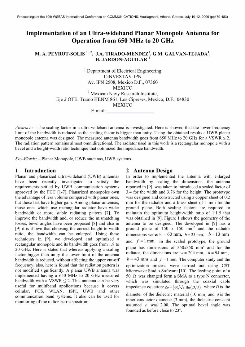
2 Antenna Design In order to implemented the antenna with enlarged bandwidth by scaling the dimensions, the antenna reported in [9], was taken to introduced a scaled factor of 3.4 for the width and 3.76 for the height. The prototype was designed and constructed using a copper sheet of 0.2 mm for the radiator and a brass sheet of 1 mm for the ground plane. Both scaling factors are required to maintain the optimum height-width ratio of 1:1.5 that was obtained in [9]. Figure 1 shows the geometry of the antenna to be designed. The developed in [9] has a ground plane of 150 x 150 mm2 and the radiator dimensions were: 60 mm,w = 25 mm,h = 13 mmb = and 1 mm.f = In the scaled prototype, the ground plane has dimensions of 350x350 mm2 and for the radiator, the dimensions are: 204 mm,w = 94 mm,h =
43 mmb = and 1 mm.f = The computer study and the optimization process were carried out using CST Microwave Studio Software [10]. The feeding point of a 50 Ω was changed form a SMA to a type N connector, which was simulated through the coaxial cable impedance equation: ( ) (60 ln )Zo Dε= d , where is the
diameter of the dielectric material (10 mm) and is the inner conductor diameter (3 mm), the dielectric constant assumed
D
d
ε was 2.08. The optimal bevel angle was founded as before close to 23°.
Proceedings of the 10th WSEAS International Conference on COMMUNICATIONS, Vouliagmeni, Athens, Greece, July 10-12, 2006 (pp479-483)
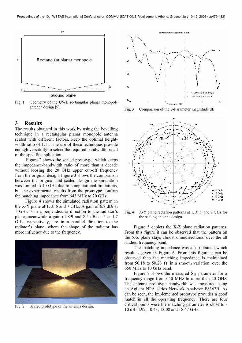
Fig. 1 Geometry of the UWB rectangular planar monopole
antenna design [9].
3 Results The results obtained in this work by using the bevelling technique in a rectangular planar monopole antenna scaled with different factors, keep the optimal height-width ratio of 1:1.5.The use of these techniques provide enough versatility to select the required bandwidth based of the specific application.
Figure 2 shows the scaled prototype, which keeps the impedance-bandwidth ratio of more than a decade without loosing the 20 GHz upper cut-off frequency from the original design. Figure 3 shows the comparison between the original and scaled design the simulation was limited to 10 GHz due to computational limitations, but the experimental results from the prototype confirm the matching impedance from 643 MHz to 20 GHz.
Figure 4 shows the simulated radiation pattern in the X-Y plane at 1, 3, 5 and 7 GHz. A gain of 6.8 dBi at 1 GHz is in a perpendicular direction to the radiator’s plane; meanwhile a gain of 8.9 and 8.5 dBi at 5 and 7 GHz, respectively, are in a parallel direction to the radiator’s plane, where the shape of the radiator has more influence due to the frequency.
Fig. 2 Scaled prototype of the antenna design.
Fig. 3 Comparison of the S-Parameter magnitude dB.
Fig. 4 X-Y plane radiation patterns at 1, 3, 5, and 7 GHz for
the scaling antenna design. Figure 5 depicts the X-Z plane radiation patterns. From this figure it can be observed that the pattern on the X-Z plane stays almost omnidirectional over the all studied frequency band.
The matching impedance was also obtained which result is given in Figure 6. From this figure it can be observed than the matching impedance is maintained from 50.18 to 50.28 Ω in a smooth variation, over the 650 MHz to 10 GHz band.
Figure 7 shows the measured S11 parameter for a frequency range from 650 MHz to more than 20 GHz. The antenna prototype bandwidth was measured using an Agilent NPA series Network Analyzer E8362B. As can be seen, the implemented prototype provides a good match in all the operating frequency. There are four critical points were the matching parameter is close to -10 dB: 4.92, 10.43, 13.08 and 18.47 GHz.
Proceedings of the 10th WSEAS International Conference on COMMUNICATIONS, Vouliagmeni, Athens, Greece, July 10-12, 2006 (pp479-483)
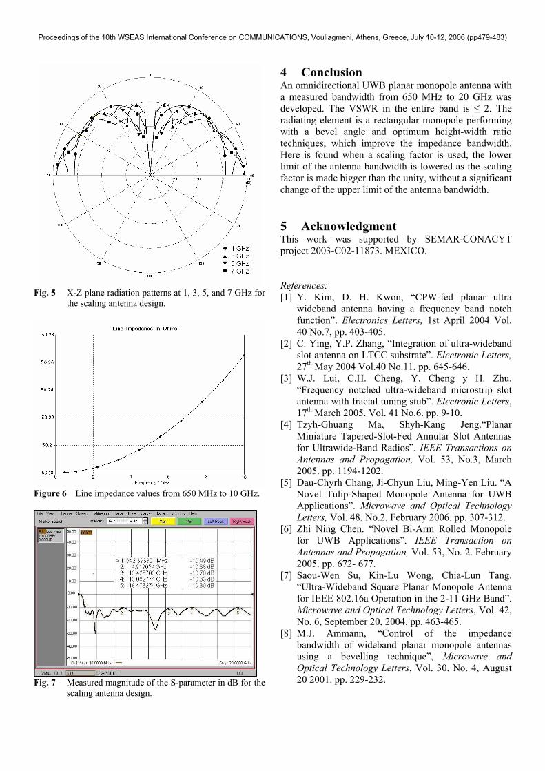
Fig. 5 X-Z plane radiation patterns at 1, 3, 5, and 7 GHz for
the scaling antenna design.
Figure 6 Line impedance values from 650 MHz to 10 GHz.
Fig. 7 Measured magnitude of the S-parameter in dB for the
scaling antenna design.
4 Conclusion An omnidirectional UWB planar monopole antenna with a measured bandwidth from 650 MHz to 20 GHz was developed. The VSWR in the entire band is ≤ 2. The radiating element is a rectangular monopole performing with a bevel angle and optimum height-width ratio techniques, which improve the impedance bandwidth. Here is found when a scaling factor is used, the lower limit of the antenna bandwidth is lowered as the scaling factor is made bigger than the unity, without a significant change of the upper limit of the antenna bandwidth. 5 Acknowledgment This work was supported by SEMAR-CONACYT project 2003-C02-11873. MEXICO.
References: [1] Y. Kim, D. H. Kwon, “CPW-fed planar ultra
wideband antenna having a frequency band notch function”. Electronics Letters, 1st April 2004 Vol. 40 No.7, pp. 403-405.
[2] C. Ying, Y.P. Zhang, “Integration of ultra-wideband slot antenna on LTCC substrate”. Electronic Letters, 27th May 2004 Vol.40 No.11, pp. 645-646.
[3] W.J. Lui, C.H. Cheng, Y. Cheng y H. Zhu. “Frequency notched ultra-wideband microstrip slot antenna with fractal tuning stub”. Electronic Letters, 17th March 2005. Vol. 41 No.6. pp. 9-10.
[4] Tzyh-Ghuang Ma, Shyh-Kang Jeng.“Planar Miniature Tapered-Slot-Fed Annular Slot Antennas for Ultrawide-Band Radios”. IEEE Transactions on Antennas and Propagation, Vol. 53, No.3, March 2005. pp. 1194-1202.
[5] Dau-Chyrh Chang, Ji-Chyun Liu, Ming-Yen Liu. “A Novel Tulip-Shaped Monopole Antenna for UWB Applications”. Microwave and Optical Technology Letters, Vol. 48, No.2, February 2006. pp. 307-312.
[6] Zhi Ning Chen. “Novel Bi-Arm Rolled Monopole for UWB Applications”. IEEE Transaction on Antennas and Propagation, Vol. 53, No. 2. February 2005. pp. 672- 677.
[7] Saou-Wen Su, Kin-Lu Wong, Chia-Lun Tang. “Ultra-Wideband Square Planar Monopole Antenna for IEEE 802.16a Operation in the 2-11 GHz Band”. Microwave and Optical Technology Letters, Vol. 42, No. 6, September 20, 2004. pp. 463-465.
[8] M.J. Ammann, “Control of the impedance bandwidth of wideband planar monopole antennas using a bevelling technique”, Microwave and Optical Technology Letters, Vol. 30. No. 4, August 20 2001. pp. 229-232.
Proceedings of the 10th WSEAS International Conference on COMMUNICATIONS, Vouliagmeni, Athens, Greece, July 10-12, 2006 (pp479-483)

[9] M. A. Peyrot-Solis, H. Jardon-Aguilar, “Ultra-wideband planar monopole antenna for operation in the 3-20 GHz Band”, VI th. International Symposium on Electromagnetic Compatibility and Electromagnetic Ecology (EMC-2005), St. Petersburg, Russia; June 2005, pp. 97 - 100.
[10] CST Microwave Studio electromagnetic field simulation software, Computer Simulation Technology, Darmstadt, Germany.
Proceedings of the 10th WSEAS International Conference on COMMUNICATIONS, Vouliagmeni, Athens, Greece, July 10-12, 2006 (pp479-483)

![DESIGN AND ANALYSIS OF WIDEBAND PLANAR MONOPOLE ANTENNAS … · 2020. 1. 16. · planar monopole antennas have attracted many studies. Techniques such as adding shorting posts [10{12],](https://img.pdfslide.us/doc/110x75/60d5231b18413f5a56506387/design-and-analysis-of-wideband-planar-monopole-antennas-2020-1-16-planar-monopole.jpg)