Embed Size (px)
Citation preview

COMPACT PLANAR WEARABLE ULTRA WIDEBAND ANTENNA FOR ON-
BODY APPLICATIONS
WADHAH ABDO MOHAMMED AL-ASHWAL
A thesis submitted in
fulfillment of the requirement for the award of the
Degree of Master of Electrical Engineering
Faculty of Electrical and Electronic Engineering
Universiti Tun Hussein Onn Malaysia
APRIL 2015

v
ABSTRACT
The increasing growth in using body area networks (BANs), wireless personal area
networks (WPANs), and medical sensors has given an interest in wearable antennas
that are made for operation on the living bodies. Engineers have not stopped at
creating a remarkable technology such as wearable systems, but also involved in
understanding the interaction of electromagnetic (EM) waves with the body.
Studying the interaction between EM waves and the body requires modeling of the
body with physical phantoms or with numerical phantoms embedded in numerical
electromagnetic codes. In this project, two ultra-wideband (UWB) planar monopole
antennas have been reported in this thesis. The substrates of the proposed antennas
have been made of jeans while radiators were made of copper tapes. Simulated and
measured performances of the antennas in terms of return loss and radiation patterns
have been discussed in this work. Recorded results have shown that the operating
frequency ranges from 3.04 GHz to 10.3 GHz and from 3.04 GHz to 11.3 GHz with
respect to -10 dB for the first and second antennas respectively. The antennas have
been tested under severe conditions such as operating in water and aggregates, and
results have been presented and discussed. Moreover, an extended study on the
safety concerns of the antennas by means of specific absorption rate (SAR) has been
included in this work. The approximated SAR has been found to be within the safety
guidelines set by Federal Communications Commission (FCC).

vi
ABSTRAK
Pertumbuhan yang semakin meningkat menggunakan rangkaian kawasan badan
(BANs), rangkaian kawasan peribadi tanpa wayar (WPANs) dan sensor perubatan
telah memberikan kepentingan kepada antena boleh pakai yang direka untuk operasi
kehidupan. Jurutera tidak berhenti untuk mewujudkan satu teknologi yang luar biasa
seperti sistem boleh pakai, tetapi juga terlibat dalam memahami interaksi
elektromagnet (EM) gelombang dengan badan. Mengkaji interaksi antara gelombang
EM dan badan memerlukan pemodelan tubuh dengan model fizikal atau dengan
model berangka tertanam dalam kod elektromagnet berangka. Dua reka bentuk
antena eka kutub ultra jalur lebar telah dilapor dan dibincangkan di dalam tesis ini.
Substratum rekabentuk antena yang dicadangkan dihasilkan daripada fabrik jeans
manakala radiator pengujaan dihasilkan daripada pita tembaga. Persembahan
simulasi dan pengukuran antena dari segi kehilangan balikan dan radiasi corak telah
dibincangkan di dalam thesis ini. Keputusan yang dicatatkan telah menunjukkan
bahawa antena beroperasi pada jalur frekuensi lebar 3.04 GHz – 10.3 GHz dan 3.04 –
11.3 GHz dengan pekali pantulan < -10 dB untuk antena pertama dan kedua. Antena
telah diuji di bawah beberapa keadaan seperti yang beroperasi di dalam air dan
agregat, dan keputusan kajian telah dibentang dan dibincangkan. Selain itu, satu
kajian lanjutan terhadap kebimbangan keselamatan antena melalui kadar penyerapan
tertentu (SAR) juga telah dibincangkan di dalam penyelidikan ini. Nilai SAR yang
diperolehi didapati telah mengikut garis panduan keselamatan yang ditetapkan oleh
Suruhanjaya Komunikasi Persekutuan (FCC).

vii
CONTENTS
TITLE i
DECLARATION ii
DEDICATION iii
ACKNOWLEDGEMENT iv
ABSTRACT v
ABSTRAK vi
CONTENTS vii
LIST OF TABLES x
LIST OF FIGURES xi
LIST OF SYMBOLS AND ABBREVIATIONS xv
LIST OF PUBLICATIONS xvi
CHAPTER 1 INTRODUCTION 1
1.1 Research Background 1
1.2 Problem Statements 4
1.3 Objectives 6
1.4 Scope of Study 6
1.5 Thesis Organization 7
CHAPTER 2 LITERATURE REVIEW 8
2.1 Antenna Parameters 8

viii
2.1.1 Radiation Pattern 8
2.1.2 Gain and Radiation Efficiency 10
2.1.3 Impedance 11
2.1.4 Bandwidth 11
2.1.5 Permittivity 12
2.1.6 Loss Tangent 14
2.2 Body Area Networks (BANs) 14
2.3 UWB Antennas and Design Techniques 15
2.4 Wearable Antennas 21
2.5 Specific Absorption Rate (SAR) and Phantoms 22
2.6 Conclusion 25
CHAPTER 3 RESEARCH METHODOLOGY 26
3.1 Introduction 26
3.2 Methodology of literature review 27
3.3 UWB design and simulation process 29
3.3.1 UWB design techniques 35
3.3.2 Numerical phantom design 40
3.4 Fabrication and measurement 41
3.5 Conclusion 43
CHAPTER 4 RESULTS AND ANALYSIS 44
4.1 Measurement of materials 44
4.2 Design 46
4.2.1 Slotted-beveled planar monopole with
notched ground-plane
46
4.2.1.1 Study of the antenna 47

ix
parameters
4.2.1.2 Performance of the
optimized antenna
50
4.2.2 Off-center fed planar monopole 57
4.2.2.1 Study of the antenna
parameters
58
4.2.2.2 Performance of the
optimized antenna
62
4.3 Fabrication and test results 66
4.4 Phantom Model for Specific Absorption
Rate (SAR)
82
4.5 Conclusion 86
CHAPTER 5 CONCLUSION 91
5.1 Conclusion 91
5.2 Future work 92
REFERENCES 96
APPENDIX A 103
VITAE 113

x
LIST OF TABLES
2.1 Relative Permittivity of Some Common Materials 13
3.1 A list of commercial electromagnetic simulation
software
30
4.1 Averaged epsilon and loss tangent for jeans. 46
4.2 Dimensions of the antenna in Figure 4.4 (units: mm) 47
4.3 Hardware specifications and runtime of the proposed
phantom
84
5.1 Comparison of proposed antenna and the previous
works
94

xi
LIST OF FIGURES
1.1 Block diagram of a typical body worn wearable system5
2.1 The 3D radiation pattern of an electrically short currentelement 9
2.2 The E-plane and H-plane patterns of an electrically shortcurrent element 9
2.3 Diagram of E field and flux density vectors about anelectric charge
13
2.4 Two steps patch with single slot and partial GND 17
2.5 Geometry of the proposed antenna in (Song et al., 2011) 18
2.6 Geometry of the proposed antenna in (Sim, 2011) 19
2.7 Examples of beveling technique 20
2.8 Types of numerical phantoms (a) homogenous phantom,(b) voxel phantom, (c) cross-section of voxel phantom 24
3.1 Research Methodology 1627
3.2 Methodology of literature review 28
3.3 Antenna design process 29
3.4 Wearable antenna design process 31
3.5 Agilent 85070E Dielectric Probe Kit, 200 MHz to 50 GHz32
3.6 Coaxial probe method 33
3.7 Two dielectric probe configurations 34
3.8 Inserting jeans properties into CST 35
3.9 Bandwidth enhancement techniques used for patch (at the
top from (a)-(d)) and the ground plane (at the bottom from
(a)-(c)) of the first proposed antenna 39
3.10 Bandwidth enhancement techniques used for the second
proposed antenna 39
3.11 The proposed human arm model developed in CST MWS:

xii
(a) perspective view, (b) cross section of the top view
(zoomed in)
40
3.12 Fabrication process 41
3.13 Measurement approach 42
4.1 Jeans dielectric constant with respect to UWB frequency
range 45
4.2 Jeans measured loss factor with respect to UWB frequency
range.
45
4.3 Jeans loss tangent with respect to UWB frequency range 45
4.4 Geometry of the first proposed antenna: (a) front view, (b)
back view 47
4.5 Ground-plane effects on bandwidth enhancement 48
4.6 Effects of adding a notch to the ground-plane 49
4.7 Performance at different values of permittivity 49
4.8 Effects of substrate thickness 50
4.9 Simulated and measured S11 parameter at free space 51
4.10.a Simulated 2D radiation pattern for the proposed antenna at
free space for frequencies 3 GHz and 5 GHz 52
4.10b Simulated 2D radiation pattern for the proposed antenna at
free space for frequencies 7 GHz and 9 GHz 53
4.11 Simulated S11 parameter at the presence of human body for
the first proposed antenna at 1.5 mm 54
4.12a Simulated 2D radiation pattern for the proposed antenna at
the presence of the body for frequencies 3 GHz and 5 GHz
at 1.5 mm
55
4.12b Simulated 2D radiation pattern for the proposed antenna at
the presence of the body for frequencies 7 GHz and 9 GHz
at 1.5 mm
56
4.13 Simulated total efficiency at the presence of the body (1.5
mm) 57
4.14 Antenna geometry: (a) front view, (b) back view 58
4.15 Ground-plane reduction stages 59
4.16 Effects of ground-plane reduction 59

xiii
4.17 Antenna feeding: (a) Centered patch and shifted feed-line
(b) Shifted patch and feed-line (optimized antenna) 60
4.18 Return loss for Figure 4.17(a) (dotted line) and Figure
4.17(b) (dashed line) 60
4.19 Return loss before applying off-center fed mechanism 61
4.20 Simulated S11 parameter at free space 62
4.21 Simulated radiation pattern at free space 63
4.22 Simulated S11 parameter at the presence of the phantom
model for the second proposed antenna at 1.5 mm 64
4.23 Simulated radiation pattern for the proposed antenna at the
presence of the body 65
4.24 Total efficiency at the presence of the body at 1.5 mm
placement from the phantom 66
4.25 First fabricated antenna 67
4.26 Measured and simulated S11 parameter for the first
proposed antenna
68
4.27 Antenna under test (top corners rolled (a) top view and (b)
perspective view), (c) diagonal corners rolled and (d) top
of the antenna rolled towards bottom
69
4.28a-b
Measured S11 results at bend conditions: (a) top corners
rolled, (b) diagonal corners rolled 72
4.28c-d
Measured S11 results at bend conditions: (c) top of the
antenna rolled towards bottom and, (d) placed close to the
arm
73
4.29 Prototype of the second proposed antenna: (a) front, (b)
back views 73
4.30 Measured results for the second proposed design 73
4.31 Measurement results for the second proposed antenna at
bend conditions: (a) top corners rolled, (b) placed close to
the arm
74
4.32 Measurement results for the second proposed antenna at
bend conditions: (c) diagonal corners rolled, (d) top of the
antenna rolled towards bottom
75

xiv
4.33 Testing setup for the proposed designs: (a) antenna
immersed with plastic bag, (b) antenna immersed without
plastic bag, (c) and (d) drying the antennas for 10 minutes,
(e) antennas buried in fine aggregates, (f) in aggregates +
water
76
4.34 Antennas in water with a plastic bag 77
4.35 Antennas in water without a plastic bag 77
4.36 Antennas buried in fine aggregates 78
4.37 Return loss for the antennas 10 minutes after exposure to
the sun 78
4.38 Return loss for the antennas inside (aggregates + water). 79
4.39 Radiation pattern of antenna I (solid line) and II (dashed
line) at 3 GHz and 4 GHz (units: θ° vs dBµV/m)
80
4.40 Radiation pattern of antenna I (solid line) and II (dashed
line) at 5 GHz and 6 GHz (units: θ° vs dBµV/m)
81
4.41 Model size and required hardware 82
4.42 Human arm model developed in CST MWS: (a)
perspective view, (b) cross section of the top view (zoomed
in)83
4.43 Total SAR [W/kg] for antenna I in the 4-layer body
phantom 85
4.44 Total SAR [W/kg] for antenna II in the 4-layer body
phantom 86
4.45 Size comparison between antenna I and II 87
4.46 Simulated return loss for antenna I and II at free space 88
4.47 Simulated return loss for antenna I and II in the vicinity of
the phantom 88
4.48 Total efficiency at free space 89
4.49 Total efficiency at the presence of the phantom 90
5.1 Example of sewing patterns versus copper adhesive tapes 93

xv
LIST OF SYMBOLS AND ABBREVIATIONS
- Mass density
- Conductivity
r - Permittivity of the substrate
reff - Effective permittivity of the substrate
AB - Absolute bandwidth
BANs - Body area networks
CST MWS - Computer Simulation Technology Microwave studio
EM - Electromagnetic
FB - Fractional bandwidth
FR-4 - Flame Retardant 4
GHz - Giga Hertz
ICNIRP - International Commission on Non-Ionizing Radiation
Protection
IEEE - Institute of Electrical and Electronics Engineers
LOS - Line-of-sight
MRI - Magnetic resonance imaging
PCB - Printed circuit boards
RAM - Radar absorbent material
RF - Radio-wave
SAR - Specific absorption rate
UHF - Ultra high frequency
UWB - Ultra-wideband
UWEN - UWB wireless embedded networks
WLAN - Wireless local area network
WPANs - Wireless personal area networks

xvi
LIST OF PUBLICATIONS
Journals:
(i) Waddah A. M. A. Khairun N. R. and Abdirahman M. S. (2015).
Performance of Ultra-Wideband Wearable Antenna under Severe
Environmental Conditions and Specific Absorption Rate (SAR) Study at
Near Distances, ARPN Journals
Proceedings:
(i) Ashwal, W. A. M. Al, & Ramli, K. N. (2013). Compact UWB wearable
antenna with improved bandwidth and low SAR. In 2013 IEEE
International RF and Microwave Conference (RFM) (pp. 90–94). Kuala
Lumpor: IEEE. doi:10.1109/RFM.2013.6757225
(ii) Ashwal, W. A. M. Al, & Ramli, K. N. (2014). Small Planar Monopole
UWB Wearable Antenna with Low SAR. In 2014 IEEE Region 10
Symposium (TENSYMP 2014) (pp. 235–239).

CHAPTER 1
INTRODUCTION
1.1 Research Background
‘Ultra-wideband’ (UWB) describes that the system/signal possesses a large bandwidth
(Allen et al., 2006). UWB systems offer high data rate, low cost equipments, multipath
immunity and both precise ranging (object location) and high speed communication at
the same time. Before UWB technology was commercialized, it has been developed
mainly in military radar systems. Today, UWB technology is changing the wireless
industry and competing with narrowband technology with its method of spreading signal
across a wide range of frequencies instead of broadcasting on separate frequencies
(Ghavami, Michael, & Kohno, 2004).
Consumer markets present most exciting opportunities for commercializing
applications that are part of our daily life. UWB can play a part in enhancing and
enriching these applications more efficiently.
As the applications in communication come in two categories, low and high data
rate, both share the two best qualities of UWB, which are low power and high capacity.
Low data rate devices, like home intruder detector usually attached by wires and cables,
can be developed into wireless device, but such solution on today’s market is restricted
by line-of-sight (LOS) interference and power issues. UWB is not bound by LOS as is

2
infrared light, since wavelengths are long by comparison and can generally bend around
or transmit through objects without impeding the connection. It is also immune against
shades and light-related interferences. The intermittent low power fashion of UWB
makes it possible to operate hundreds of devices in the same space without interfering
one another.
Indoor devices like computer peripherals can be improved in an innovative way.
They can be made wireless and utilized to share the space. This shared space can include
a wireless printer, monitor, audio speakers and more of computer accessories such as
wireless mouse and keyboard.
Medically, sensors are used to monitor the critical life signs of a patient.
Monitoring systems come with wires and cables connected to these sensors which are
attached to the patient’s body. This creates uncomfortable scenario for the patient
surrounded by wires in constant matter. UWB wireless sensor network makes that
choice avoidable.
There is the so-called UWB wireless embedded networks (UWEN) project that is
working on developing systems with low rate communication for location and tracking
applications. Such application targets to improve security of material goods, find our
keys, keep pace with children, find people in situations, including fire fighters in burning
building, police officers in distress, and track people at recreational activities such as
cross country skiing and athletics. The key concept is to develop carried low power
UWB devices and data from users transmitted to fixed nodes and exchange signal time
of arrival information which enables to determine the location of the device (Siwiak &
McKeown, 2004).
The increasing growth in using body area networks (BANs), wireless personal
area networks (WPANs), and medical sensors has given an interest in wearable antennas
that are made for operation on the living bodies. They are found in portable radio
equipments used by the military, the pager and mobile phones. The introduction of body
worn medical sensors and wireless medical sensor networks has enabled doctors and
specialists to monitor patients at a distance (Guha & Antar, 2010).
Engineers are not done with only creating remarkable technology such as
wearable systems, but also involved in understanding the interaction of electromagnetic
3
(EM) waves with the body in body-centric communications and wireless systems that
operate close to the body. This helps understand the nature of electromagnetic properties
of body tissues and how they vary significantly with tissue type and frequency. This
understanding enables the development of antennas and transceivers for such
communications systems. Studying the interaction between EM waves and the body
requires modeling of the body with physical phantoms or with numerical phantoms
embedded in numerical electromagnetic codes.
A phantom is defined as a simulated biological body or as a physical model
mimicking the characteristics of the biological tissues. The aim of modeling a phantom
is to predict and explore the interaction between the human tissue and the
electromagnetic fields. For this purpose, phantoms have been used extensively in
medical research on the effects of electromagnetic radiation on health, as well as in
development of various methods of medical diagnosis and treatment, such as X-ray,
magnetic resonance imaging (MRI) scan, and hyperthermia.
With the increase of communication devices that will be worn or operating close
to the human body, the phantoms became an essential tool for testing safety of such
devices. Various safety standards specify the acceptable limits of radiation in terms of
specific absorption rate (SAR), which can be measured using a number of methods
involving phantoms. Phantoms are also a useful tool in studying the EM wave
propagation around and inside the human body. Such studies are necessary to help
design powerful, robust, reliable, wearable low-cost communication devices. Phantoms
can also provide a steady, controllable propagation environment, which cannot be easily
realized with human subjects.
Many numerical phantoms have been modeled for theoretical analyses and
computational simulations. Theoretical phantoms are simple-shaped phantoms and
generally used in theoretical analyses. However, it is necessary to use voxel phantom, a
more realistic numerical phantom, in order to calculate the characteristics of antennas
close to the human body, which is composed of many voxels.
Therefore, it still remains as an engineering challenge to explore the area of
wearable application in all aspects and produce suitable, reliable, and safe technology
for these applications.
4
1.2 Problem Statements
Body worn system consists of electronic devices normally situated on or in close
proximity to the human body. Figure 1.1 shows that both short range and long range
wireless communication plays an important role in mobile wearable systems. However
these communication systems consist of several subparts of which antenna is the most
essential one and the quality and reliability of a connection will depend a great deal on
optimal design of antennas.
The wired connection between devices in a body area network (BAN) may be
inconvenient for a user. This may be due partly to weight and partly to restriction in
movement and prescriptions placed on clothing design and manufacture. Therefore, the
need for comfortability is pushing the trend of wireless communication in place of wired
one.
The making of wearable UWB antenna requires an operating frequency in the
range of 3.1 GHz – 10.6 GHz, flexible radiators and substrates and consideration of
safety limits standards by providing low readings of the specific absorption rate (SAR).
The size of the antenna is one of the critical issues in UWB system design,
because it greatly affects the bandwidth and gain. Therefore, the miniaturization of
antennas capable of providing abroad impedance matching bandwidth and offering an
acceptable gain is a challenging task (Chen & Yang, 2008).
The human body is composed of a large variety of tissue types, each having
different dielectric properties, and this data is important for the design of wearable
antennas (Guha & Antar, 2010). Body-centric communication systems involve the
interaction between electromagnetic waves and the body tissues. It is most important to
account for the overall performance of the antenna in the vicinity of human body. At the
same time, it is an engineering task to optimize the design of the antenna in order to
comply with safety guidelines, such as those standardized by the International
Commission on Non-Ionizing Radiation Protection (ICNIRP) (Ahlbom et al., 1998) and
the Institute of Electrical and Electronics Engineers (IEEE) (“IEEE Recommended

5
Practice for Determining the Peak Spatial-Average Specific Absorption Rate (SAR) in
the Human Head from Wireless Communications Devices: Measurement Techniques,”
2003).
Figure 1.1: Block diagram of a typical body worn wearable system (Bashir, 2009)
In order to obtain a wide bandwidth, planar monopole antenna design is utilized in this
research. Monopole antennas provide an omni-directional radiation pattern and wide
matching impedance. To further broaden the bandwidth of the first proposed design to
cover the range of UWB, matching techniques such as applying slots and bevels to the
rectangular patch and truncation and notches to the ground plane are employed.
Parameters of those techniques, such as size, critically affect the impedance bandwidth
and ensuring a proper dimension is required. The second proposed design has avoided
the employment of those techniques, except applying truncation to the ground. Instead,
off-center feeding mechanism has been applied to the square patch that has been shifted
from the center of the substrate. The combination of those two techniques has enhanced
the bandwidth and simplified the second proposed design which gave it more
performance stability as the tests results have shown.
Centralprocessingunit (CPU)
AUDIOMicrophone
Speaker
INPUT MouseKeyboard
Touch screenSpeech
recognition
Batteries
WIRELESSLong range
datatransmission
WIRELESSShort range
datatransmission
POSITIONINGGPS
DISPLAYLCD Plasma

6
As for wearability, textiles are good candidates for making the proposed
antennas flexible. As textiles have low permittivity, which contributes to the bandwidth
improvement, jeans has been elected for the substrates of the proposed antennas. A low
reading of SAR is also one of the concerns of wearable systems. Therefore, the proposed
four-layer numerical phantom model (bone, muscle, fat and skin) can provide an
acceptable accuracy for the performance of the antennas as well as the computation of
SAR.
1.3 Objectives
The main objectives of the proposed work are:
i. To design a compact planar antenna that covers the range of ultra wideband
spectrum (3.1 GHz – 10.6 GHz).
ii. To explore the utilization of textile materials in making wearable UWB antennas.
iii. To study the effect of a numerical phantom on the proposed designs and ensure
that the specific absorption rate (SAR) comply with the safety limit standards.
1.4 Scope of Study
This study will focus on the performance improvement in terms of bandwidth for the
ultra wideband antenna designed using jeans as a substrate. In order to succeed, a
number of procedures have been identified as listed below:
i. Focus on designing small sized planar UWB antenna.
ii. Obtain the characteristics of jeans substrate, tangent loss and permittivity ε r, by
means of measurement.
iii. Use the finite difference time domain method (FDTD) to study the performance
the proposed UWB antenna before the actual prototype is built.

7
iv. Develop four-layer (bone, muscle, fat and skin) numerical phantom model to
approximate the performance of the proposed antennas for on-body condition
and evaluate the SAR.
1.5 Thesis Organization
The thesis is organized in four chapters as follows:
Chapter 1 gives a brief background of the research and defines the objective,
problem statement and scopes.
Chapter 2 contains the literature review, which examines a comprehensive
background of other related research works and the fundamental antenna parameters that
should be considered in designing UWB antenna. It also summarizes some studies on
narrowband and wideband wearable antennas, especially on their physical construction.
Finally, a brief study of phantoms and specific absorption rate (SAR) is also included.
Chapter 3 is about the design methodology applied in this proposed work and
discusses in details the methodology of the literature review, UWB antenna design
process, design techniques, numerical phantom model, and fabrication and measurement
setup.
Chapter 4 analyzes the results yielded from the proposed work. There is a brief
section on the measurement setup and results for the selected material jeans. The
proposed slotted-beveled planar monopole antenna with notched ground-plane has been
studied in details. The second proposed design, off-center fed planar monopole, has also
been studied widely. Results of the antennas operating under external forces such as
bending, and applied environmental conditions such as wetness were examined in depth.
This chapter also studies the phantom model proposed for SAR computation and
antenna performance on-body.
Chapter 5 concludes the researches that have been done in this thesis.
Suggestions for future work are also given in this chapter.

CHAPTER 2
LITERATURE REVIEW
This section of the report summarizes some of the fundamental theories on antennas
parameters, introduction to body area networks (BANs), brief study on bandwidth
enhancement techniques, and some previous works in the area of UWB antennas as well
as wearable antennas in general. Part of the study focuses on the methods used to
evaluate wearability of the antennas in terms of flexibility and safety concerns.
2.1 Antenna Parameters
An antenna is a basic component of systems where it is used as a link between
transmitter and free space or free space and receiver. The basic parameters of the
antenna include the radiation pattern, radiation intensity, gain, directivity, antenna
efficiency, beamwidth the bandwidth. (Huang & Boyle, 2008; Seybold, 2005) discuss
some of the important parameters of the antenna in the following section.
2.1.1 Radiation Pattern
The radiation pattern of an antenna is a plot of the radiated field/power as a function of
the angle at a fixed distance, which should be large enough to be considered far field.
The three-dimensional (3D) radiation pattern of the electrically short current element is

9
plotted in Figure 2.1. The 3D pattern is an excellent illustration of the radiated field
distribution as a function of angle θ and φ in space.
Figure 2.1: The 3D radiation pattern of an electrically short current element
Most antennas have certain symmetrical features, thus, in reality, the most
important patterns are the radiation patterns in the two main planes: the E-plane and the
H-plane. The E-plane is the plane that the electric field E lies on, while the H-plane is
the plane that the magnetic field H is on. For the ideal current element case, the electric
field is Eθ and the magnetic field is Hφ, thus the E-plane pattern is the field Eθ measured
as a function of θ when the angle φ and the distance are fixed, while the H-plane pattern
is the field Eθ measured as a function of φ when the angle θ and the distance are fixed.
Figure 2.2: The E-plane and H-plane patterns of an electrically short current element

10
The E-plane (at φ = 0) and H-plane (at θ = π/2) patterns of the short current
element are shown in Figure 2.2. This antenna has an omni-directional pattern in the H-
plane; this is a desirable feature for many mobile antennas since the antenna is not
sensitive to orientation. Another special case is called the isotropic antenna, which has
the same radiation power at all angles. This is a hypothetical case and cannot be realized
in practice, but sometimes it is used as a reference for analysis (Huang & Boyle, 2008).
2.1.2 Gain and Radiation Efficiency
For a real antenna, there will be certain angles of radiation, which provide greater
power density than others (when measured at the same range). The directivity of an
antenna is defined as the ratio of the radiated power density at distance, d, in the
direction of maximum intensity to the average power density over all angles at distance,
d. This is equivalent to the ratio of the peak power density at distance d, to the average
power density at d:
Power density at in direction of maximum power
Mean power density at
dD
d (2.1)
Thus an isotropic antenna has a directivity of D = 1. When the antenna losses are
included in the directivity, this becomes the antenna gain
2
Power density at in maximum direction
4T
dG
P d
(2.2)
where PT is the power applied to the antenna terminals
24 d is the surface area of a sphere with radius d
is the total efficiency, which accounts for all losses in the antenna, including resistive
and taper losses (T R
)

11
Antenna gain can be described as the power output, in a particular direction,
compared to that produced in any direction by an isotropic radiator. The gain is usually
expressed in dBi, decibels relative to an ideal isotropic radiator (Seybold, 2005). While
the radiation efficiency factor of the antenna is the ratio of the radiated power to the
input power accepted by the antenna (Huang & Boyle, 2008):
t
in
P
e P (2.3)
2.1.3 Impedance
An antenna presents load impedance or driving point impedance to whatever system is
connected to its terminals. The driving point impedance is ideally equal to the radiation
resistance of the antenna. In practical antennas, the driving point impedance also
includes resistive losses within the antenna and other complex impedance contributors
such as cabling and connectors within the antenna. The driving point impedance of an
antenna is important in that a good impedance match between the circuit (such as a
transceiver) and the antenna is required for maximum power transfer. Maximum power
transfer occurs when the circuit and antenna impedances are matched (Seybold, 2005).
2.1.4 Bandwidth
The bandwidth of an antenna may be defined in terms of one or more physical
parameters. As shown in equation 2.4, the bandwidth may be calculated by using the
frequencies fu and fl at the upper and lower edges of the achieved bandwidth:

12
2( )100% bandwidth 100%
( )BW =
:1 bandwidth 100%
u l
u l
f f
f f
fu
fl
(2.4)
The bandwidth of an antenna can be defined for impedance, radiation pattern and
polarization. First, a satisfactory impedance bandwidth is the basic consideration for all
antenna design, which allows most of the energy to be transmitted to an antenna from a
feed or a transmission system at a transmitter, and from an antenna to its load at a
receiver in a wireless communication system. Second, a designated radiation pattern
ensures that maximum or minimum energy is radiated in a specific direction. Finally, a
defined polarization of an antenna minimizes possible losses due to polarization
mismatch within its operating bandwidth (Z. Chen & Chia, 2006).
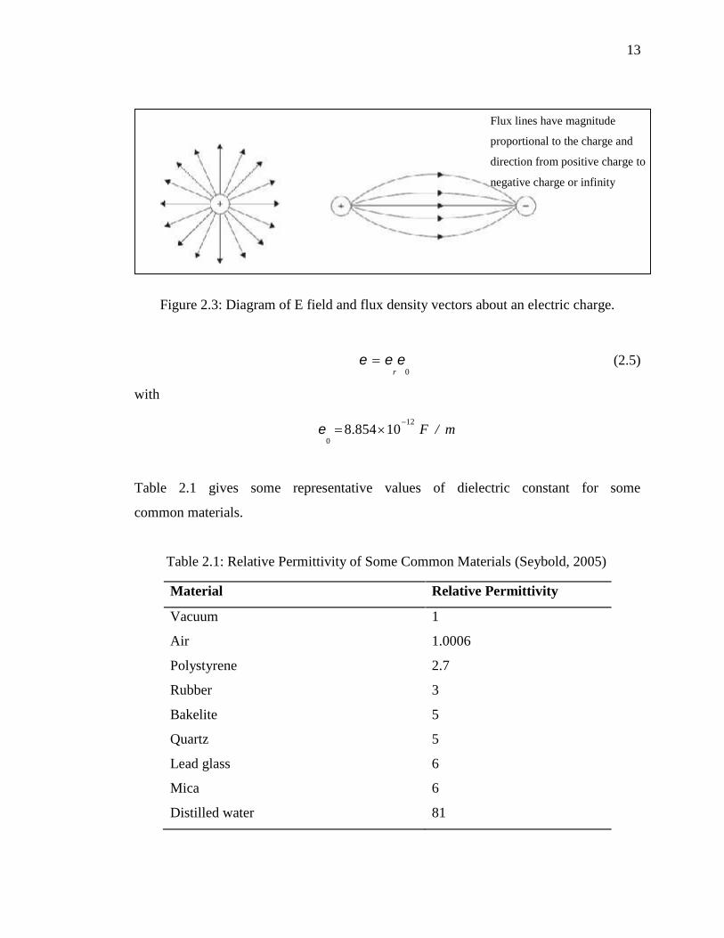
2.1.5 Permittivity
Since the electric or E-field depends not only on the flux density, but also on the
permittivity of the material or environment through which the wave is propagating, it is
valuable to have some understanding of permittivity. Permittivity is a property that is
assigned to a dielectric (conductors do not support static electric fields). The
permittivity is a metric of the number of bound charges in a material and has units of
farads per meter. Permittivity is expressed as a multiple of the permittivity of free space,
ε0. This term is called the relative permittivity, εr, or the dielectric constant of the
material (Seybold, 2005).
13
Figure 2.3: Diagram of E field and flux density vectors about an electric charge.
0r (2.5)
with
12
08.854 10 F / m
Table 2.1 gives some representative values of dielectric constant for some
common materials.
Table 2.1: Relative Permittivity of Some Common Materials (Seybold, 2005)
Material Relative Permittivity
Vacuum 1
Air 1.0006
Polystyrene 2.7
Rubber 3
Bakelite 5
Quartz 5
Lead glass 6
Mica 6
Distilled water 81
Flux lines have magnitude
proportional to the charge and
direction from positive charge to
negative charge or infinity

14
2.1.6 Loss tangent
In a practical sense, most materials lie on a continuum of properties. The
characterization of a material as a conductor or dielectric is based on the dominant
property of the material. For lossy dielectrics, the permittivity or dielectric constant is
given by
1' j
'
(2.6)
where σ is the conductivity of the dielectric. Thus the dielectric constant is a complex
value with the imaginary part representing the loss characteristics of the material. The
loss tangent is defined as σ/(ωε’) and represents the ratio of conductive current to the
displacement current in the material. A material can be considered low loss if the loss
tangent is less than 0.1, and it is considered high loss if the loss tangent is greater than
10 (Seybold, 2005).
2.2 Body Area Networks (BANs)
Current communication systems are driven by the concept of being connected anywhere
at any time. An essential part of this concept is a user-centric approach in which services
are constantly available and systems provide reconfigurability, unobtrusiveness and true
extension of the human’s mind. Body area networks (BANs) consist of a number of
nodes and units placed on the human body or in close proximity, such as on everyday
clothing. Currently, they are used to receive or transmit simple information which
requires very low processing capabilities, e.g. patient monitoring systems that transmit
low data rate information (heart rate, blood pressure, etc.). However, some high
performance and complex units are needed in the future to provide the facilities for
powerful computational processing with high data rates for applications such as video
streaming and heavy data communications. A major drawback of current body-worn

15
systems is the wired communication which is often undesirable because of the
inconvenience for the user. Other connection methods have been proposed for solving
this problem, including the use of smart textiles and communication by the currents on
the user’s body (B Allen et al., 2006).
The radio propagation around the human body is a complex phenomenon,
although it takes place over only very short distance ranges. For communication between
two devices placed on the human body, transmitted signals can arrive at the receiver in
three ways (Hao & Alomainy, 2008):
propagation through the body,
diffraction around the body, and
reflections from nearby scatterers in the radio environment.
Signals in the Gigahertz frequency range diffracting around the body attenuate
due to absorption by human tissue. In addition, the original transmitted signal spreads
out in time, due to the frequency-dependent dispersion by the antenna-body system. This
attenuation and signal spreading likely depends on a number of random factors,
including the curvature of the body, the exact position of the antennas, the position of
the arms, the type of materials along the various signal paths, and so forth.
The ultra wideband low transmit power requirements allow longer battery life for
body-worn units. This leads to UWB being a potential candidate for BAN. The
possibility of transmitting data with various requirements in short range communication
with low power consumption offered by UWB introduces an attractive solution for
wireless BAN (WBAN) and implant radio system designers (B Allen et al., 2006).
2.3 UWB Antennas and Design Techniques
Recently, a variety of UWB antennas have been experimentally investigated and
reported with different geometries. But very few people have discussed about how
flexible the antenna is, especially when attachment to the body is demanded such as in
16
UWB body centric communications. There are some techniques that have been
experimentally examined which have resulted broadband antennas. The following is a
list of some of design techniques used for achieving wide bands (Gouda & Yousef,
2012):
Slots: wide rectangular slot, square-ring slot, E-slot, multi-inverted cone slot, L-
and T-slot, V-slot, double U-slots, etc.
Beveling the bottom edges of the radiating element.
Using steps on the patch.
Notches at the feeding position in the ground plane.
Large number of proposed antennas is patch type due to their performances for a
variety of UWB applications compared to wire antennas. Planar antennas are attractive
due to their simple geometric structures and ease of fabrication. Most of UWB antennas
mainly focus on the slot and monopole antennas for their ability of providing a wide
operating bandwidth. Considerable attention has been paid to broadband planar
monopole antennas for their attractive merits, such as ultra wide frequency band, good
radiation properties, simple structure and ease of fabrication. Broadband planar
monopole antennas have taken many shapes such as half-disc, circle, ellipse, and
rectangle.
There are many types of broadband directional antennas such as the Vivaldi, log-
periodic, cavity-backed, waveguide, horn, and dish antennas that cover the entire 3.1–
10.6 GHz band (109%). The undesirable fact about them is that they are electrically
large, and have a high profile, while planar monopoles, disc cone, and slot antennas
provide omni- and bi-directional radiation patterns and have a low gain and back
radiation pattern, therefore they are not suitable for unidirectional communication
(Azim, Islam, & Misran, 2010).

17
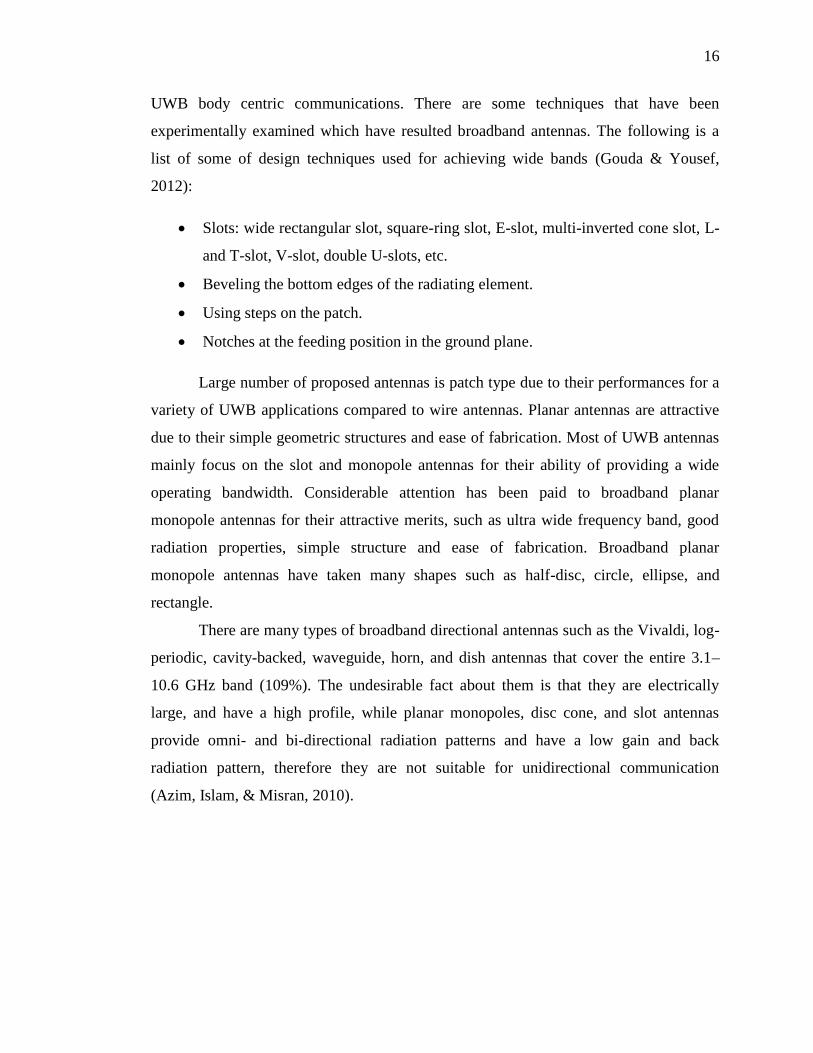
Figure 2.4: Two steps patch with single slot and partial ground (Choi, Park, Kim, &
Park, 2004)
Choi et al., 2004, the proposed antenna was designed to operate from 3.2 to 12
GHz. It consists of a rectangular patch with two steps, a single slot on the patch, and a
reduced ground plane printed on FR4 substrate. The design is hard to depict on jeans
substrate at cutting conductive materials stage. This study does not include the
performance of the antenna using textile substrate nor the Specific Absorption Rates
(SAR). Figure 2.1 shows the antenna proposed in (Choi et al., 2004).
(UWB) step-slot antenna with a rotated patch was demonstrated in (Song, Yin,
Chen, Fan, & Gao, 2011) with area of 25×25mm2 and enhanced impedance bandwidth
of 117.5%. The parameters of the square notch and angle of the rotated patch (l, α)
should be carefully adjusted so that the whole UWB band can be obtained, which makes
it difficult to fabricate from textiles. This study did not discuss whether or not the
radiation of the antenna meets with SAR limits. Figure 2.2 shows the proposed antenna.

18
Figure 2.5: Geometry of the proposed antenna in (Song et al., 2011)
K. Chen et al. 2011, designed a planar microstrip-fed wideband monopole from
egg-shaped patch printed off-center along the y-axis on a 1.6-mm thick FR4 substrate
with dimension 35×77 mm2 and depicted a semi-elliptical fractal-complementary slot
into the ground plane as shown in Figure 2.3. The triangular notch at the feeding
position in the ground plane is used to achieve impedance matching that results in
bandwidth enhancement, while introducing the semi-elliptical fractal-complementary
slot into the ground plane to reduce the ground plane effect by suppressing the electric
currents on the ground plane at lower-end operating frequency (Sim, 2011).

19
Figure 2.6: Geometry of the proposed antenna in (Sim, 2011)
It has been found that the addition of a bevel to the lower corners of the square
planar monopole increases the impedance bandwidth as demonstrated in many reported
studies. Applying modifications to the bottom edge of the radiating element by using
beveling technique has shown that the upper edge frequency is shifted upward
(Antonino-Daviu, E. and Cabedo-Fabres, M. and Ferrando-Bataller, M. and Valero-
Nogueira, 2003; Z. N. Chen, See, & Qing, 2007; Hong, Ling, Tarn, & Chung, 2007;
Koski, Vena, Sydanheimo, Ukkonen, & Rahmat-Samii, 2013; Thomas, Krishna,
Gopikrishna, Kalappura, & Aanandan, 2011; K. Zhang, Li, & Long, 2010).

20
Figure 2.7: Examples of beveling technique
(a) as in (Antonino-Daviu, E. and Cabedo-Fabres, M. and Ferrando-Bataller, M. and
Valero-Nogueira, 2003), (b) as in (Thomas et al., 2011), (c) as in (Foudazi, Hassani, &
Mohammad ali nezhad, 2012) and d) as in (Z. N. Chen et al., 2007).
The lower- and upper-edge frequencies can be optimized and improved by
applying notches slits to the radiator and ground plane of the antenna. This technique is
used to reduce the ground-plane effect on the performance of a small printed UWB
antenna (Bao & Ammann, 2007). In (Z. N. Chen et al., 2007), a notch is cut from the
radiator and a strip is asymmetrically attached to the radiator in order to further reduce
the overall size of the printed antenna as shown in Figure 2.3d.
In brief, modification techniques are generally used to broaden the impedance
bandwidth of small patch antennas and optimize the characteristics of the radiation
pattern. These adjustments have an effect on matching mechanism between the radiating
element and ground plane. As a result, the bandwidth and the overall size of radiating
elements of the antenna are optimized. Planar monopole antennas are good candidates
for these techniques and have proven achieving wide impedance bandwidth, omni-
directional radiation pattern, compact and simple structure, low cost and ease of
construction (Azim et al., 2010; Gouda & Yousef, 2012).
a b c d

21
2.4 Wearable Antennas
The introduction of body-centric networks has led to the development of body worn
wireless devices. The body-centric network consists of a number of nodes and units
placed on the human body or in close proximity such as on clothing. As low-power
transmission is required for operating body worn wireless devices, the human body can
provide a communication channel between wireless wearable devices to and from a
wireless body-centric network (Alomainy, Hao, Hu, Parini, & Hall, 2006).
Body-worn applications require flexible surfaces and circuit components to
provide superior electrical and mechanical performances. This has led to the creation of
a new technology using embroidered conductive fibers on polymer. Flexible conductors
are constructed from silver-coated p-phenylene-2, 6-benzobisoxazole (PBO) fibers (e-
fibers). The e-fibers provides inherent mechanical strength (due to their polymer core),
together with high electrical conductivity owed to the silver coating. Lightweight and
conformal electro-textiles based on conductive threads and fabrics provide compelling
means to fabricate seamlessly garment-integrated antennas substrates (L. Zhang, Wang,
& Volakis, 2012), (Koski et al., 2013).
Wearable tags are meant to be used near the body. As a result, the human body
absorbs RF energy, reducing the overall antenna performance. In this application, also
humidity, bending, and stretching likely affect the performance of the antenna. Sewing
pattern and thread densities can also affect the overall performance of an embroidered
antenna as investigated in (Moradi, Bjorninen, Ukkonen, & Rahmat-Samii, 2012).
Transmission in body area networks for proposed dual-band wearable metallic
button antenna has been studied in (Sanz-Izquierdo, Miller, Batchelor, & Sobhy, 2010).
The design was proposed to operate at 2.4 GHz WLAN and the HiperLAN/2 bands. The
study focuses on on-body propagating line of sight and non-line of sight channels and
how the body attenuates the channel.
Davis & Stutzman, 2005, have investigated the feasibility of the ultra-wideband
half-disk structures based on camouflage cloth (substrate) and compared the
performance of solid copper and woven versions (radiators). The study has concluded

22
that solid copper version has shown good measured return loss characteristics, omni-
directional patterns, and acceptable transient response.
Antenna mounting for ultra-wideband on-body communication has been studied
in (Thompson, Cepeda, Hilton, Beach, & Armour, 2011). The authors have proposed a
means of modifications made to the mounting procedure for two UWB antennas suitable
for BAN applications, one commercially available antenna and one fabric antenna to
reduce their coupling with the body. The proposed antenna modification employs radar
absorbent material (RAM) to shield the antenna from the user. This alteration decreases
the amount of radiation passing into the body, but still allows the principal propagation
mechanisms of UWB BAN.
In (Osman, Rahim, Samsuri, & Ali, 2011), the authors proposes three different
antenna structures. The substrate of the designed antennas was made from two types of
fabrics: jeans and flannel. The dimensions of the proposed antennas are 40 mm × 40 mm
for antenna I, and 60 mm × 60 mm for antenna II and III.
Most of the studies of wearable antennas have not stepped into the area of
Specific Absorption Rates (SAR) test, which is required for studying the power
absorption issues and meet the standards in order to avoid harm to human body. The aim
of this study includes producing antennas with compact geometries and low SAR.
2.5 Specific Absorption Rate (SAR) and Phantoms
SAR is the time derivative (rate) of the incremental energy (dW) absorbed by (dissipated
in) an incremental mass (dm) contained in a volume element (dV) of a given density (ρ).= =SAR is expressed in units of watts per kilogram (W/kg) or equivalently
milliwatts per gram (mW/g). Some refer to it as a so-called volume-SAR, expressed in
units of mW/cm3, where mass density has been set to unity. SAR can be related to the E-
field at a point as in equation 2.7

23
= | |(2.7)
where σ is conductivity of the tissue (S/m), ρ is mass density of the tissue (kg/m3) and E
is the electric field strength (V/m).
Specific absorption rate—peak spatial-average is determined by the maximum
local SAR averaged over a specified volume or mass, e.g., any 1 g or 10 g of tissue in
the shape of a cube. SAR is expressed in W/kg or equivalently mW/g.
A considerable attention has been given to the impact of the interaction between
electromagnetic (EM) fields and the human body as in (Chatterjee, Gandhi, Hagmann, &
Riazi, 1980; Chatterjee, Hagmann, & Gandhi, 1980; Rosen, Stuchly, & Vander Vorst,
2002; Stuchly, 1993). The interaction between human head and cellular phones has been
studied in (Kuster & Balzano, 1992; Meier, Hombach, Kastle, & Kuster, 1997), while
interaction between human head and terminal antennas has been studied in (Christ &
Kuster, 2005; Gandhi, Lazzi, & Furse, 1996). These works have been conducted in order
to examine whether or not the antenna radiation exceed the limits set by the standards
(Ahlbom et al., 1998), (ANSI, 1992).
CST STUDIO SUITE developers have also shared a note on “Body Wearable
Antenna: Simulation Challenges” of RFID, ISM and UWB antennas (Rütschlin, 2013).
The note discusses construction and body model handling when dealing with complex
geometries. The note has also included a comparison between homogenous and voxel
phantoms in terms of S11 and SAR considering full and partial body. The difference was
found to be in small fractions (according to the example studied in the note: SAR: 0.667
W/kg for homogenous model and SAR: 0.883 W/kg for voxel model). It also studied the
same example on full and reduced model. The result was found to be very close (SAR:
0.667 W/kg for full homogeneous body model and SAR: 0.644 W/kg for partial
homogeneous body model).

24
Figure 2.8: Types of numerical phantoms: (a) homogenous phantom, (b) voxel phantom,(c) cross-section of voxel phantom (Rütschlin, 2013).
Studies on the evaluation of the power absorbed by human body and the Specific
Absorption Rate (SAR) have been conducted in different methods. Kuster (Kuster &
Balzano, 1992) has evaluated the absorption mechanism for homogenous body model
while Kivekas (Kivekäs, Lehtiniemi, & Vainikainen, 2004) has considered homogenous
and layered body model. Klemm (Klemm & Troester, 2006) has further studied the
interactions of UWB antennas used in wearable applications on homogenous and layered
human body models. SAR results of very near antennas to the body have been computed
in order to investigate the influence of the body. The first evaluation of SAR was on a
simple homogenous model composing one tissue (muscle of 50 mm thickness). The
second model consisted of three-layers (skin: 0.5, 1 and 2 mm; fat: 1, 3 and 6 mm;
muscle: 50 mm). The study assumed all models to be planar neglecting the curvature of
the body.
In (Kawai & Ito, 2004), a simple evaluation method of estimating local average
SAR has been proposed based on COST244 cubical and spherical head model
(numerical phantom), followed by studying the effect of the distance and the frequency
on the average SAR and comparing the obtained evaluations with realistic head model.
Lightweight spherical COST244 tissue-equivalent phantom for evaluation of antenna
performances has been proposed in (Yamaguchi, Arai, Shimizu, & Tanaka, 2008).
(a) (b) (c)

96
REFERENCES
Ahlbom, A., Bergqvist, U., Bernhardt, J. H., Cesarini, J. P., Grandolfo, M. & Hietanen,
M. (1998). Guidelines for limiting exposure to time-varying electric, magnetic,
and electromagnetic fields (up to 300 GHz). International Commission on Non-
Ionizing Radiation Protection. Health Phys, 74(4), 494–522.
Allen, B., Dohler, M., Okon, E., & Malik, W. (2006). Ultra-wideband: antennas and
propagation for communications, radar and imaging. (B. Allen, M. Dohler, E. E.
Okon, W. Q. Malik, A. K. Brown, & D. J. Edwards, Eds.). Chichester, UK: John
Wiley & Sons, Ltd. doi:10.1002/0470056843
Alomainy, A., Hao, Y., Hu, X., Parini, C., & Hall, P. (2006). UWB on-body radio
propagation and system modelling for wireless body-centric networks. IEE
Proceedings-Communications, 107–114. doi:10.1049/ip-com
ANSI, A. (1992). IEEE C95. 1-1992: IEEE Standard for Safety Levels with Respect to
Human Exposure to Radio Frequency Electromagnetic Fields, 3 kHz to 300
GHz, The. Inc., New York, NY. Retrieved from
http://scholar.google.com/scholar?hl=en&btnG=Search&q=intitle:IEEE+Standar
d+for+Safety+Levels+with+Respect+to+Human+Exposure+to+Radio+Frequenc
y+Electromagnetic+Fields,+3+kHz+to+300+GHz#1
Antonino-Daviu, E., Cabedo-Fabres, M., Ferrando-Bataller, M. & Valero-Nogueira, A.
(2003). Wideband double-fed planar monopole antennas. Electronics Letters,
39(23), 3–4. doi:10.1049/el
Ashwal, W. A. M. Al. & Ramli, K. N. (2013). Compact UWB wearable antenna with
improved bandwidth and low SAR. In 2013 IEEE International RF and
Microwave Conference (RFM) (pp. 90–94). Penang, Malaysia: IEEE.
doi:10.1109/RFM.2013.6757225
97
Azim, R., Islam, M. T. & Misran, N. (2010). Printed Planar Antenna for Wideband
Applications. Journal of Infrared, Millimeter, and Terahertz Waves, 969–978.
doi:10.1007/s10762-010-9655-7
Balanis, C. (2005). Antenna theory: analysis and design (3rd Edition, p. 1136 pages).
John Wiley and Sons. Retrieved from
http://as.wiley.com/WileyCDA/WileyTitle/productCd-047166782X.html
Bao, X. & Ammann, M. (2007). Investigation on UWB printed monopole antenna with
rectangular slitted ground plane. Microwave and Optical Technology Letters,
49(7), 1585–1587. doi:10.1002/mop
Bashir, S. (2009). Design and synthesis of non uniform high impedance surface based
wearable antennas.
Chahat, N., Zhadobov, M. & Sauleau, R. (2012). Broadband Tissue-Equivalent Phantom
for BAN Applications at Millimeter Waves. IEEE Transactions on Microwave
Theory and Techniques, 60(7), 2259–2266. doi:10.1109/TMTT.2012.2195196
Chatterjee, I., Gandhi, O. P., Hagmann, M. J. & Riazi, A. (1980). Plane-wave spectrum
approach for the calculation of electromagnetic absorption under near-field
exposure conditions. Bioelectromagnetics, 1(4), 363–377.
Chatterjee, I., Hagmann, M. J. & Gandhi, O. P. (1980). Electromagnetic absorption in a
multilayered slab model of tissue under near-field exposure conditions.
Bioelectromagnetics, 1(4), 379–388.
Chen, W.-S. & Yang, K. (2008). Design of a CPW-fed Printed Antenna for Ultra-
wideband Applications. Microwave Journal, 51(120), 1–4. Retrieved from
http://www.microwavejournal.com/articles/5891-design-of-a-cpw-fed-printed-
antenna-for-ultra-wideband-applications
Chen, Z. & Chia, M. (2006). Broadband planar antennas: design and applications.
Retrieved from
http://books.google.com/books?hl=en&lr=&id=0Tgw_UpEhx0C&oi=fnd&pg=P
R7&dq=Broadband+Planar+Antennas:+Design+and+Applications&ots=sa4h-
AIdLL&sig=Q0U0Se4dzjnDBlKGkES_yRjKNME

98
Chen, Z. N., See, T. S. P. & Qing, X. (2007). Small Printed Ultrawideband Antenna
With Reduced Ground Plane Effect. IEEE Transactions on Antennas and
Propagation, 55(2), 383–388. doi:10.1109/TAP.2006.889823
Choi, S. H., Park, J. K., Kim, S. K. & Park, J. Y. (2004). A new ultra-wideband antenna
for UWB applications. Microwave and Optical Technology Letters, 40(5), 399–
401. doi:10.1002/mop.11392
Christ, A. & Kuster, N. (2005). Differences in RF energy absorption in the heads of
adults and children. Bioelectromagnetics, 26(S7), S31–S44.
Davis, W. & Stutzman, W. (2005). Wearable Ultra-Wideband Half-Disk Antennas. In
2005 IEEE Antennas and Propagation Society International Symposium (Vol.
3A, pp. 500–503). IEEE. doi:10.1109/APS.2005.1552297
DeGroot, M. H. & Schervish, M. J. (2002). Probability and Statistics (4E ed.). Addison-
Wesley. Retrieved from
http://books.google.com.my/books?id=iH4ZAQAAIAAJ
Eldek, A. A. (2006). Numerical analysis of a small ultra wideband microstrip-fed tap
monopole antenna. Progress In Electromagnetics Research, 65, 59–69.
Foudazi, A., Hassani, H. R. & Mohammad Ali Nezhad, S. (2012). Small UWB Planar
Monopole Antenna With Added GPS/GSM/WLAN Bands. IEEE Transactions
on Antennas and Propagation, 60(6), 2987–2992.
doi:10.1109/TAP.2012.2194632
Gabriel, C. (2007). Tissue equivalent material for hand phantoms. Physics in Medicine
and Biology, 52(14), 4205–10. doi:10.1088/0031-9155/52/14/012
Gabriel, C. (2013). Body Tissue Dielectric Parameters Tool. Retrieved July 3, 2013,
from http://www.fcc.gov/encyclopedia/body-tissue-dielectric-parameters
Gandhi, O. P., Lazzi, G. & Furse, C. M. (1996). Electromagnetic absorption in the
human head and neck for mobile telephones at 835 and 1900 MHz. IEEE
Transactions on Microwave Theory and Techniques, 44(10), 1884–1897.
doi:10.1109/22.539947
Ghavami, M., Michael, L. & Kohno, R. (2004). Ultra Wideband Signals and Systems in
Communication Engineering. Wiley. Retrieved from
http://books.google.com.my/books?id=9v8p_YE6HpoC

99
Gouda, M. & Yousef, M. Y. M. (2012). Bandwidth Enhancement Techniques
Comparison for Ultra Wideband Microstrip Antennas for Wireless Application.
Journal of Theoretical and Applied Information Technology, 35(2), 184–193.
Guha, D. & Antar, Y. M. M. (2010). Microstrip and Printed Antennas. (D. Guha & Y.
M. M. Antar, Eds.). Chichester, UK: John Wiley & Sons, Ltd.
doi:10.1002/9780470973370
Hao, Y. & Alomainy, A. (2008). Antennas and Propagation for Body-Centric Wireless
Communications. IEEE Antennas and Propagation Magazine, 50(2), 148–148.
doi:10.1109/MAP.2008.4562277
Hayouni, M., Choubani, F. & Denden, M. (2011). A Novel Compact Ultra-wideband
Rectangular Shaped Antenna. Progress in Electromagnetics Research
Symposium Proceedings, 381–385.
Hirt, W. (2003). Ultra-wideband radio technology: overview and future research.
Computer Communications, 26(1), 46–52. doi:10.1016/S1403-3664(02)00119-6
Hong, C.-Y., Ling, C.-W., Tarn, I.-Y. & Chung, S.-J. (2007). Design of a Planar
Ultrawideband Antenna With a New Band-Notch Structure. IEEE Transactions
on Antennas and Propagation, 55(12), 3391–3397.
doi:10.1109/TAP.2007.910486
Huang, Y. & Boyle, K. (2008). Antennas: From Theory to Practice. Chichester, UK:
John Wiley & Sons, Ltd. doi:10.1002/9780470772911
IEEE Recommended Practice for Determining the Peak Spatial-Average Specific
Absorption Rate (SAR) in the Human Head from Wireless Communications
Devices: Measurement Techniques. (2003). IEEE Std 1528-2003, 1–120.
doi:10.1109/IEEESTD.2003.94414
Kawai, H. & Ito, K. (2004). Simple Evaluation Method of Estimating Local Average
SAR. IEEE Transactions on Microwave Theory and Techniques, 52(8), 2021–
2029. doi:10.1109/TMTT.2004.832028
Kivekäs, O., Lehtiniemi, T. & Vainikainen, P. (2004). On the general energy-absorption
mechanism in the human tissue. Microwave and Optical Technology Letters,
43(3), 195–201. doi:10.1002/mop.20418

100
Klemm, M. & Troester, G. (2006). EM Energy Absorption in The Human Body Tissues
due to UWB Antennas. Progress In Electromagnetics Research, 62, 261–280.
doi:10.2528/PIER06040601
Koski, K., Vena, A., Sydanheimo, L., Ukkonen, L. & Rahmat-Samii, Y. (2013). Design
and Implementation of Electro-Textile Ground Planes for Wearable UHF RFID
Patch Tag Antennas. IEEE Antennas and Wireless Propagation Letters, 12, 964–
967. doi:10.1109/LAWP.2013.2276007
Kuster, N. & Balzano, Q. (1992). Energy absorption mechanism by biological bodies in
the near field of dipole antennas above 300 MHz. IEEE Transactions on
Vehicular Technology, 41(1), 17–23. doi:10.1109/25.120141
Lazebnik, M., Madsen, E. L., Frank, G. R. & Hagness, S. C. (2005). Tissue-mimicking
phantom materials for narrowband and ultrawideband microwave applications.
Physics in Medicine and Biology, 50(18), 4245–58. doi:10.1088/0031-
9155/50/18/001
Lee, K. F. & Luk, K. M. (2010). Microstrip Patch Antennas. Imperial College Press.
Retrieved from http://books.google.com.my/books?id=Ped4pt-vNUYC
Lilja, J., Salonen, P., Kaija, T. & de Maagt, P. (2012). Design and Manufacturing of
Robust Textile Antennas for Harsh Environments. IEEE Transactions on
Antennas and Propagation, 60(9), 4130–4140. doi:10.1109/TAP.2012.2207035
Meier, K., Hombach, V., Kastle, R. & Kuster, N. (1997). The dependence of
electromagnetic energy absorption upon human-head modeling at 1800 MHz.
IEEE Transactions on Microwave Theory and Techniques, 45(11), 2058–2062.
doi:10.1109/22.644237
Moradi, E., Bjorninen, T., Ukkonen, L. & Rahmat-Samii, Y. (2012). Effects of Sewing
Pattern on the Performance of Embroidered Dipole-Type RFID Tag Antennas.
IEEE Antennas and Wireless Propagation Letters, 11, 1482–1485.
doi:10.1109/LAWP.2012.2231393
Ojaroudi, M., Ghobadi, C. & Nourinia, J. (2009). Small Square Monopole Antenna With
Inverted T-Shaped Notch in the Ground Plane for UWB Application. IEEE
Antennas and Wireless Propagation Letters, 8, 728–731.
doi:10.1109/LAWP.2009.2025972

101
Osman, M. A. R., Rahim, M. K. A., Samsuri, N. A. & Ali, M. E. (2011). Compact and
embroidered textile wearable antenna. In 2011 IEEE International RF &
Microwave Conference (Vol. 4, pp. 311–314). doi:10.1109/RFM.2011.6168756
Osman, M., Rahim, M. & Azfar, M. (2011). Design, implementation and performance of
ultra-wideband textile antenna. Progress In Electromagnetics Research,
27(December 2010), 307–325. Retrieved from
http://www.jpier.org/PIERB/pier.php?paper=10102005
Rosen, A., Stuchly, M. A. & Vander Vorst, A. (2002). Applications of RF/microwaves
in medicine. IEEE Transactions on Microwave Theory and Techniques, 50(3),
963–974. doi:10.1109/22.989979
Rütschlin, M. (2013). Body Wearable Antenna simulation challenges. In Euroupean
User Conference.
Sangeetha, R. (2013). Notch Band Antenna for Wireless Applications, 69(9), 9–11.
Sanz-Izquierdo, B. (2007). Compact UWB Wearable Antenna. Antennas and
Propagation, 2-3(April), 121–124. Retrieved from
http://ieeexplore.ieee.org/xpls/abs_all.jsp?arnumber=4218481.
Sanz-Izquierdo, B., Miller, J. a., Batchelor, J. C. & Sobhy, M. I. (2010). Dual-band
wearable metallic button antennas and transmission in body area networks. IET
Microwaves, Antennas & Propagation, 4(2), 182. doi:10.1049/iet-
map.2009.0010
Scarpello, M. L., Kurup, D., Rogier, H., Vande Ginste, D., Axisa, F., Vanfleteren, J. &
Vermeeren, G. (2011). Design of an Implantable Slot Dipole Conformal Flexible
Antenna for Biomedical Applications. IEEE Transactions on Antennas and
Propagation, 59(10), 3556–3564. doi:10.1109/TAP.2011.2163761
Seybold, J. S. (2005). Introduction to RF Propagation. Hoboken, NJ, USA: John Wiley
& Sons, Inc. doi:10.1002/0471743690
Sim, C. (2011). A Compact Monopole Antenna for Super Wideband Applications. IEEE
Antennas and Wireless Propagation Letters, 10, 488–491.
doi:10.1109/LAWP.2011.2157071
Siwiak, K. & McKeown, D. (2004). Ultra-Wideband Radio Technology. Chichester,
UK: John Wiley & Sons, Ltd. doi:10.1002/0470859334

102
Song, K., Yin, Y., Chen, B., Fan, S. & Gao, F. (2011). Bandwidth Enhancement Design
of Compact UWB Step-Slot Antenna with Rotated Patch. In Progress In
Electromagnetics Research (Vol. 22, pp. 39–45). Retrieved from
http://jpier.org/PIERL/pier.php?paper=11030112
Stuchly, M. A. (1993). Electromagnetic fields and health. IEEE Potentials, 12(2), 34–39.
doi:10.1109/45.283813
Thomas, P., Krishna, D. D., Gopikrishna, M., Kalappura, U. G. & Aanandan, C. K.
(2011). Compact planar ultra-wideband bevelled monopole for portable UWB
systems. Electronics Letters, 47(20), 1112. doi:10.1049/el.2011.2285
Thompson, W., Cepeda, R., Hilton, G., Beach, M. A. & Armour, S. (2011). An
Improved Antenna Mounting for Ultra-Wideband On-Body Communications and
Channel Characterization. IEEE Transactions on Microwave Theory and
Techniques, 59(4), 1102–1108. doi:10.1109/TMTT.2011.2114130
Yamaguchi, H., Arai, H., Shimizu, Y. & Tanaka, T. (2008). Lightweight tissue-
equivalent phantom for evaluation of antenna performances. 2008 Asia-Pacific
Microwave Conference, 1–4. doi:10.1109/APMC.2008.4958520
Yang, S. S., Lee, K.-F., Kishk, A. A. & Luk, K.-M. (2008). Design and Study of
Wideband Single Feed Circularly Polarized Microstrip Antennas. Progress In
Electromagnetics Research, 80, 45–61. doi:10.2528/PIER07110604
Zhang, K., Li, Y. & Long, Y. (2010). Band-Notched UWB Printed Monopole Antenna
With a Novel Segmented Circular Patch. IEEE Antennas and Wireless
Propagation Letters, 9, 1209–1212. doi:10.1109/LAWP.2010.2099095
Zhang, L., Wang, Z. & Volakis, J. L. (2012). Textile Antennas and Sensors for Body-
Worn Applications. IEEE Antennas and Wireless Propagation Letters, 11, 1690–
1693. doi:10.1109/LAWP.2013.2239956
![DESIGN AND ANALYSIS OF WIDEBAND PLANAR MONOPOLE ANTENNAS … · 2020. 1. 16. · planar monopole antennas have attracted many studies. Techniques such as adding shorting posts [10{12],](https://img.pdfslide.us/doc/110x75/60d5231b18413f5a56506387/design-and-analysis-of-wideband-planar-monopole-antennas-2020-1-16-planar-monopole.jpg)