Embed Size (px)
Citation preview
20 March 2005 Ken Moffeit LCWS 1
Highlights from the MDI workshopSpin Rotation System for 2 IR’s
Downstream polarimetry
Ken Moffeit
20 March 2005 Ken Moffeit LCWS 2
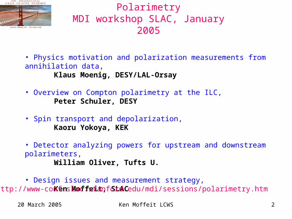
PolarimetryMDI workshop SLAC, January 2005
• Physics motivation and polarization measurements from annihilation data, Klaus Moenig, DESY/LAL-Orsay
• Overview on Compton polarimetry at the ILC,Peter Schuler, DESY
• Spin transport and depolarization,
Kaoru Yokoya, KEK • Detector analyzing powers for upstream and downstream polarimeters,
William Oliver, Tufts U. • Design issues and measurement strategy,
Ken Moffeit, SLAC
http://www-conf.slac.stanford.edu/mdi/sessions/polarimetry.htm

20 March 2005 Ken Moffeit LCWS 3
Summary of MDI Workshop Polarization Session
• Three ways to measure polarization: upstream, downstream, data• Issues to Understand:
• Difference of incoming, outgoing and luminosity weighted polarization.• Correlations between electron and positron polarization.• Polarimeter corrections for data methods.
• More concrete questions:• Is downstream polarimetry with 2 mrad crossing angle possible?• If no, is upstream polarimetry enough?• Can we believe CAIN for depolarization?• Do we understand the polarization transport well enough?• Backgrounds.• Light sources for different polarimeters (backgrounds, correlations)• Switching between IRs, how, how often?• Real Designs• Common issues with beam energy/luminosity spectrum: correlations between beams, momentum-polarization correlations.
PolarimetryMDI workshop SLAC, January 2005
Klaus Moenig
20 March 2005 Ken Moffeit LCWS 4
Beam Delivery Systems Layout from Mark Woodley
IR2
IR1
2 mrad crossing angle
20 mrad crossing angle
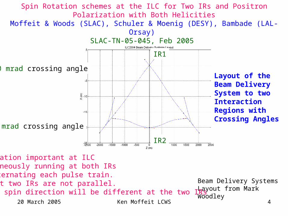
Spin Rotation schemes at the ILC for Two IRs and Positron Polarization with Both Helicities
Moffeit & Woods (SLAC), Schuler & Moenig (DESY), Bambade (LAL-Orsay) SLAC-TN-05-045, Feb 2005
• Polarization important at ILC• Simultaneously running at both IRs
by alternating each pulse train.• Beams at two IRs are not parallel. so spin direction will be different at the two IRs
Layout of the Beam Delivery System to two Interaction Regions with Crossing Angles
20 March 2005 Ken Moffeit LCWS 5
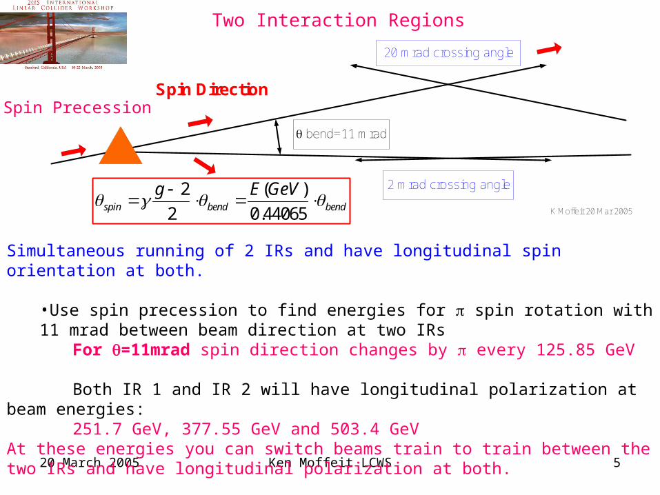
Two Interaction Regions
Simultaneous running of 2 IRs and have longitudinal spin orientation at both.
•Use spin precession to find energies for spin rotation with 11 mrad between beam direction at two IRs
For =11mrad spin direction changes by every 125.85 GeV
Both IR 1 and IR 2 will have longitudinal polarization at beam energies: 251.7 GeV, 377.55 GeV and 503.4 GeV
At these energies you can switch beams train to train between the two IRs and have longitudinal polarization at both.
K Moffeit 20 Mar 2005
Spin Direction
bend=11 mrad
20 mrad crossing angle
2 mrad crossing angle
bendbendspin
GeVEg
44065.0
)(
2
2
Spin Precession
20 March 2005 Ken Moffeit LCWS 6
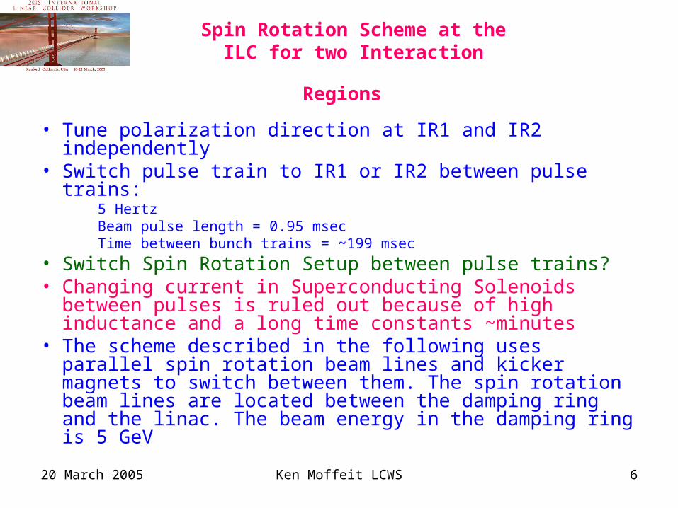
Spin Rotation Scheme at the ILC for
two Interaction Regions • Tune polarization direction at IR1 and IR2 independently• Switch pulse train to IR1 or IR2 between pulse trains:
5 HertzBeam pulse length = 0.95 msecTime between bunch trains = ~199 msec
• Switch Spin Rotation Setup between pulse trains?• Changing current in Superconducting Solenoids between
pulses is ruled out because of high inductance and a long time constants ~minutes
• The scheme described in the following uses parallel spin rotation beam lines and kicker magnets to switch between them. The spin rotation beam lines are located between the damping ring and the linac. The beam energy in the damping ring is 5 GeV
20 March 2005 Ken Moffeit LCWS 7
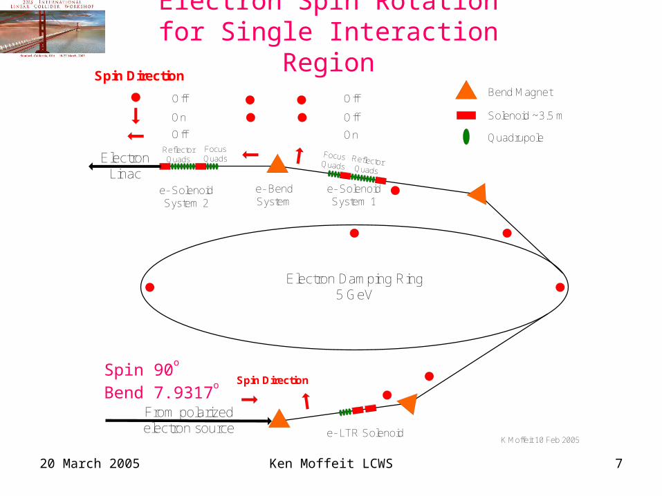
Electron Spin Rotation for Single Interaction Region
Electron Damping Ring5 GeV
K Moffeit 10 Feb 2005
ReflectorQuads
FocusQuads
ReflectorQuads
FocusQuads
On
Off
Off
Off
Off
On
ElectronLinac
Spin Direction
Spin Direction
From polarizedelectron source
Bend Magnet
Solenoid ~3.5 m
Quadrupole
e- SolenoidSystem 1
e- SolenoidSystem 2
e- BendSystem
e- LTR Solenoid
Spin 90o
Bend 7.9317o
20 March 2005 Ken Moffeit LCWS 8
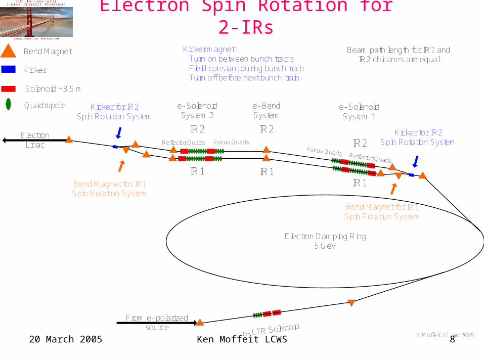
Electron Spin Rotation for 2-IRs
Beam path length for IR1 andIR2 chicanes are equal
Kicker magnet:Turn on between bunch trainsField constant during bunch trainTurn off before next bunch train
K Moffeit 27 Jan 2005
Electron Damping Ring5 GeV
IR2Reflector Quads Focus Quads
IR1
Reflector Quads
Focus Quads
e- LTR SolenoidFrom e- polarized
source
ElectronLinac
e- SolenoidSystem 1
e- SolenoidSystem 2
e- BendSystem
IR2
IR1
Kicker for IR2Spin Rotation System
IR1
IR2
Kicker for IR2Spin Rotation System
Bend Magnet for IR1Spin Rotation System
Bend Magnet for IR1Spin Rotation System
Kicker
Bend Magnet
Solenoid ~3.5 m
Quadrupole
20 March 2005 Ken Moffeit LCWS 9
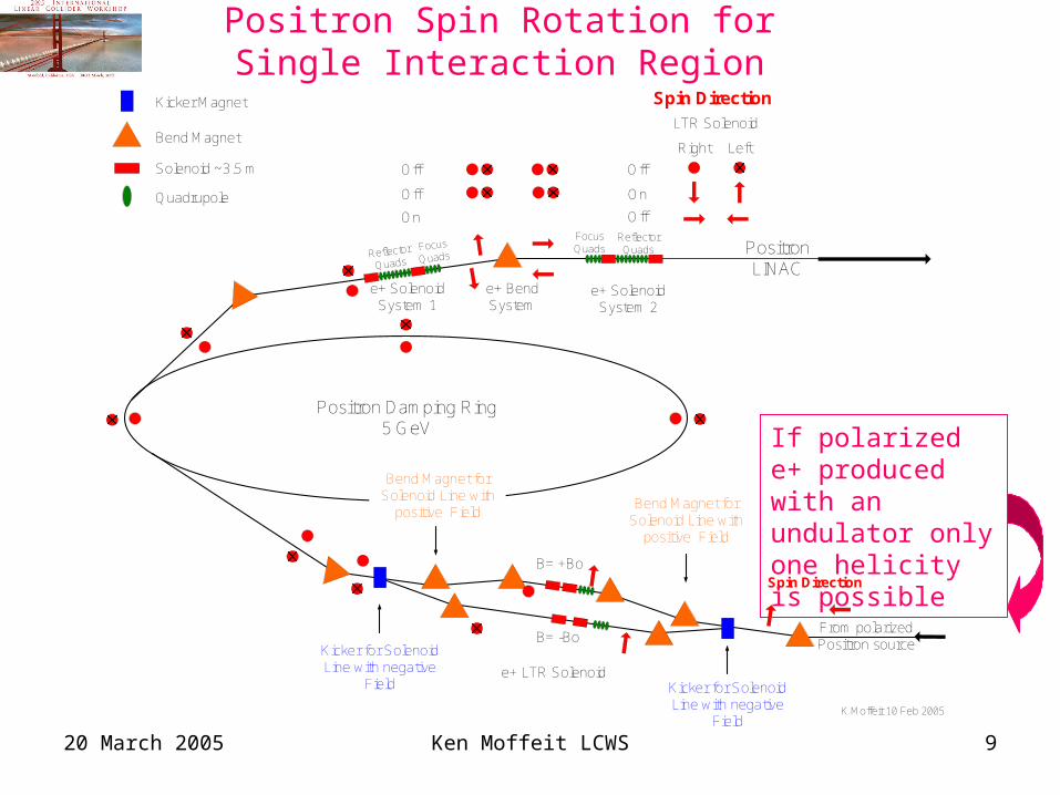
Positron Spin Rotation for Single Interaction Region
PositronLINAC
Positron Damping Ring5 GeV
K Moffeit 10 Feb 2005
Reflector
Quads
Focus
Quads
ReflectorQuads
FocusQuads
On
Off
Off
Off
Off
On
Spin DirectionLTR Solenoid
Right Left
From polarizedPositron source
Spin Direction
B= -Bo
Bend Magnet
Solenoid ~3.5 m
Quadrupole
Kicker Magnet
e+ SolenoidSystem 1
e+ SolenoidSystem 2
e+ BendSystem
Kicker for SolenoidLine with negative
Field
Bend Magnet forSolenoid Line with
positive Field
e+ LTR Solenoid
B= +Bo
Kicker for SolenoidLine with negative
Field
Bend Magnet forSolenoid Line with
positive Field
If polarized e+ produced with an undulator only one helicity is possible
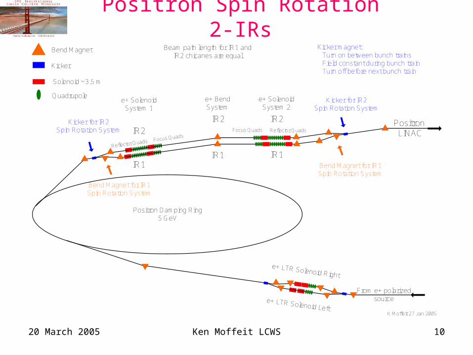
20 March 2005 Ken Moffeit LCWS 10
Positron Spin Rotation 2-IRsBeam path length for IR1 and
IR2 chicanes are equalKicker magnet:
Turn on between bunch trainsField constant during bunch trainTurn off before next bunch train
K Moffeit 27 Jan 2005
Positron LINAC
From e+ polarizedsource
Positron Damping Ring5 GeV
IR2Reflector QuadsFocus Quads
IR1Reflector Quads Focus Quads
e+ LTR Solenoid Left
e+ LTR Solenoid Right
e+ SolenoidSystem 1
e+ SolenoidSystem 2
e+ BendSystem
IR2
IR1
Kicker for IR2Spin Rotation System
IR1
IR2
Kicker for IR2Spin Rotation System
Bend Magnet for IR1Spin Rotation System
Bend Magnet for IR1Spin Rotation System
Kicker
Bend Magnet
Solenoid ~3.5 m
Quadrupole
20 March 2005 Ken Moffeit LCWS 11
Comments for parallel beam lines
• The chicanes for the parallel beam lines are in the horizontal plane so there are no bends in the vertical plane since the beam emittance is critical in that dimension. Beam energy is 5 GeV in the parallel beam lines.
• Path lengths for the parallel beams need to be almost equal with any difference small compared to the bunch length. Path length correction chicanes can be added to the parallel beam lines if necessary.
• The pair of kicker magnet can be powered in series from the same current source to minimize beam jitter entering the linac.
• The double-solenoid spin rotator system is a small energy band-pass system. It must be located upstream of the RF used to compress the bunch length. The beam at the damping ring extraction has an rms relative energy spread of about 0.1% rather than the 1-2% rms level in the bunch compressor.
20 March 2005 Ken Moffeit LCWS 12
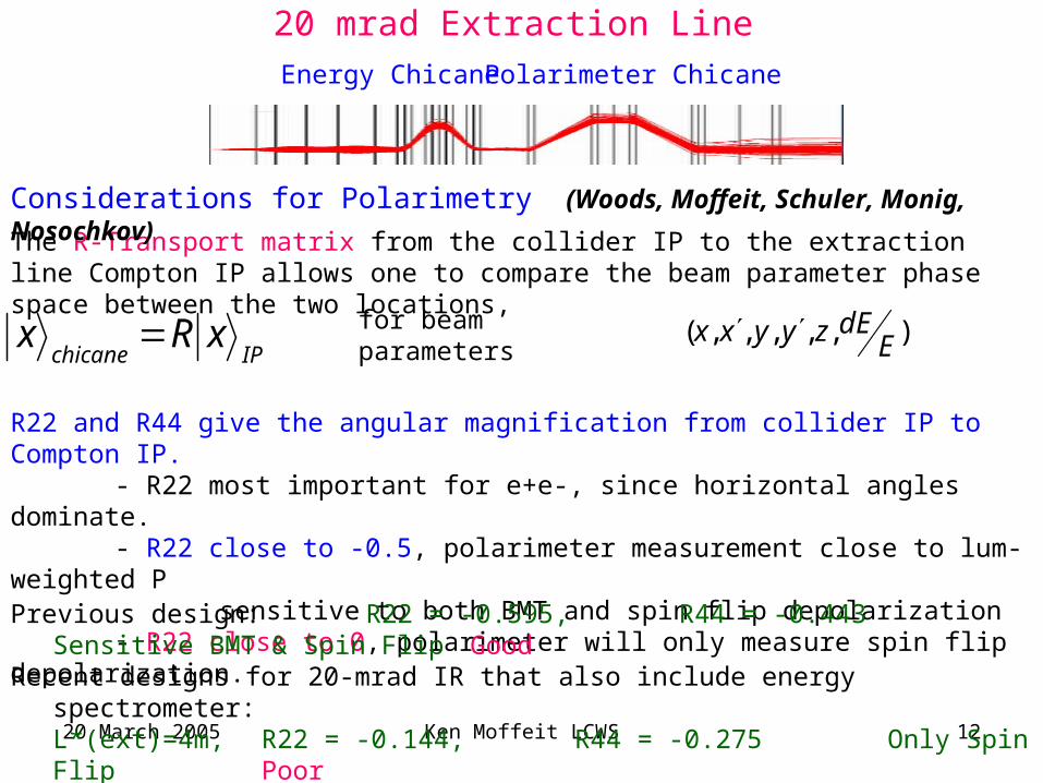
20 mrad Extraction Line
IPchicanexRx
The R-Transport matrix from the collider IP to the extraction line Compton IP allows one to compare the beam parameter phase space between the two locations,
for beam parameters ),,,,,( EdEzyyxx
Considerations for Polarimetry (Woods, Moffeit, Schuler, Monig, Nosochkov)
Polarimeter ChicaneEnergy Chicane
R22 and R44 give the angular magnification from collider IP to Compton IP.- R22 most important for e+e-, since horizontal angles dominate.- R22 close to -0.5, polarimeter measurement close to lum-weighted P
sensitive to both BMT and spin flip depolarization- R22 close to 0, polarimeter will only measure spin flip depolarization.
Previous design: R22 = -0.595, R44 = -0.443 Sensitive BMT & Spin Flip Good
Recent designs for 20-mrad IR that also include energy spectrometer:L*(ext)=4m, R22 = -0.144, R44 = -0.275 Only Spin Flip PoorL*(ext)=15m, R22 = -0.326, R44 = -0.419 BMT? Spin Flip ok Marginal
20 March 2005 Ken Moffeit LCWS 13
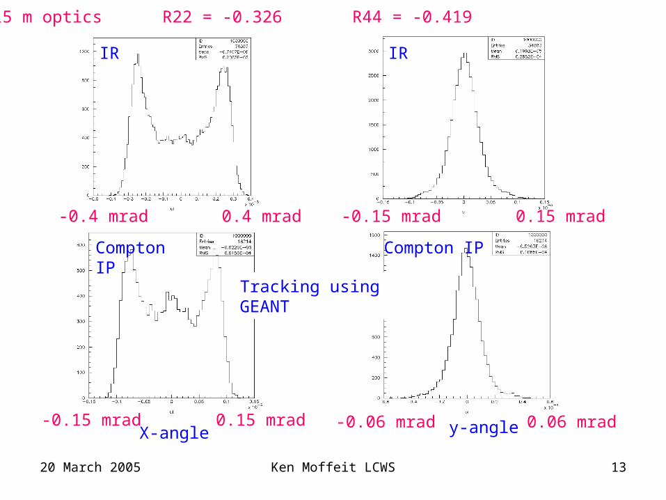
X-angle y-angle 0.06 mrad-0.06 mrad0.15 mrad-0.15 mrad
0.4 mrad-0.4 mrad
Compton IP
IR
Compton IP
0.15 mrad-0.15 mrad
L*= 15 m optics R22 = -0.326 R44 = -0.419
Tracking using GEANT
IR
20 March 2005 Ken Moffeit LCWS 14
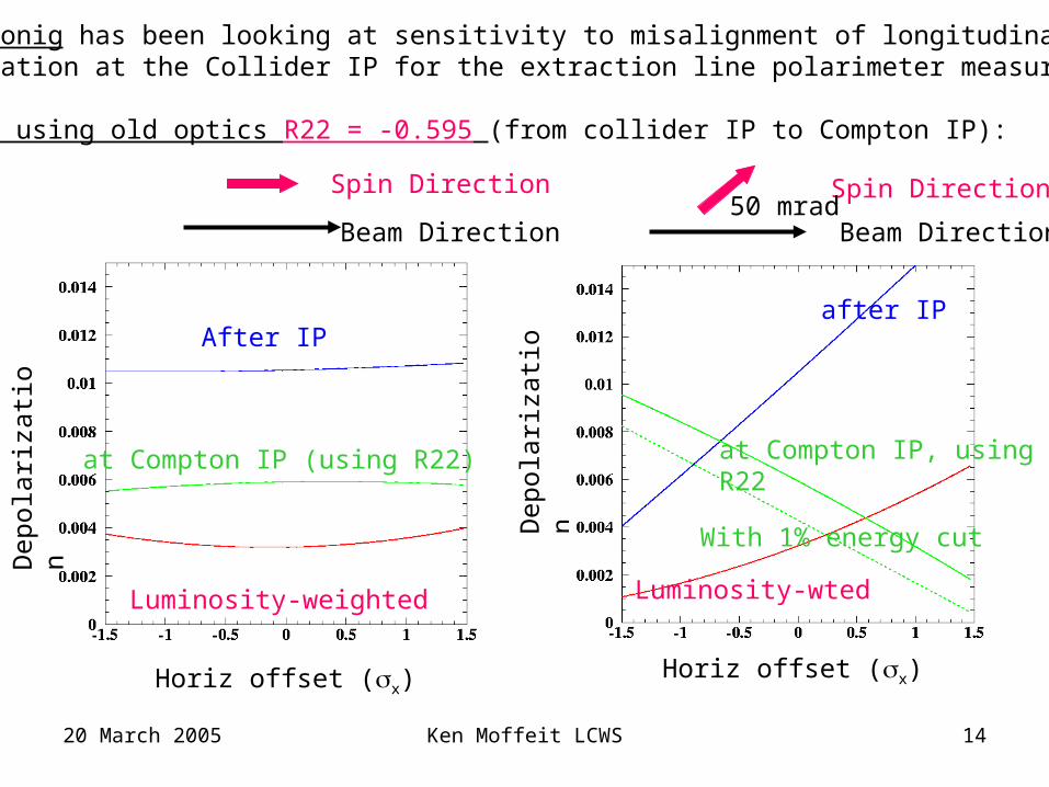
After IP
at Compton IP (using R22)
Luminosity-weighted
Horiz offset (x)
Dep
olar
izat
ion
after IP
at Compton IP, using R22
Luminosity-wted
With 1% energy cutDep
olar
izat
ion
Horiz offset (x)
Beam Direction
Spin Direction
Beam Direction
Spin Direction50 mrad
Klaus Monig has been looking at sensitivity to misalignment of longitudinalPolarization at the Collider IP for the extraction line polarimeter measurements.
Results using old optics R22 = -0.595 (from collider IP to Compton IP):
20 March 2005 Ken Moffeit LCWS 15
Horiz offset (x)
Dep
olar
izat
ion
Horiz offset (x)
Dep
olar
izat
ion
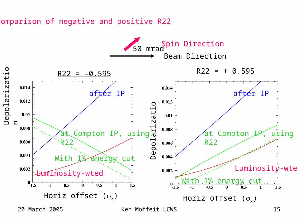
after IP
at Compton IP, using R22
Luminosity-wted
With 1% energy cut
R22 = -0.595 R22 = + 0.595
after IP
at Compton IP, using R22
Luminosity-wted
With 1% energy cut
Comparison of negative and positive R22
Beam Direction
Spin Direction50 mrad
20 March 2005 Ken Moffeit LCWS 16
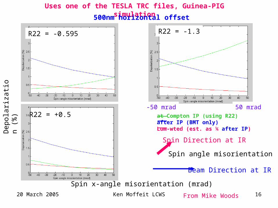
R22 = -1.3R22 = -0.595
at Compton IP (using R22)after IP (BMT only)Lum-wted (est. as ¼ after IP)
Uses one of the TESLA TRC files, Guinea-PIG simulation
R22 = +0.5
Spin x-angle misorientation (mrad)
Dep
olar
izat
ion
(%)
Beam Direction at IR
Spin Direction at IR
Spin angle misorientation
From Mike Woods
500nm horizontal offset
-50 mrad 50 mrad
20 March 2005 Ken Moffeit LCWS 17
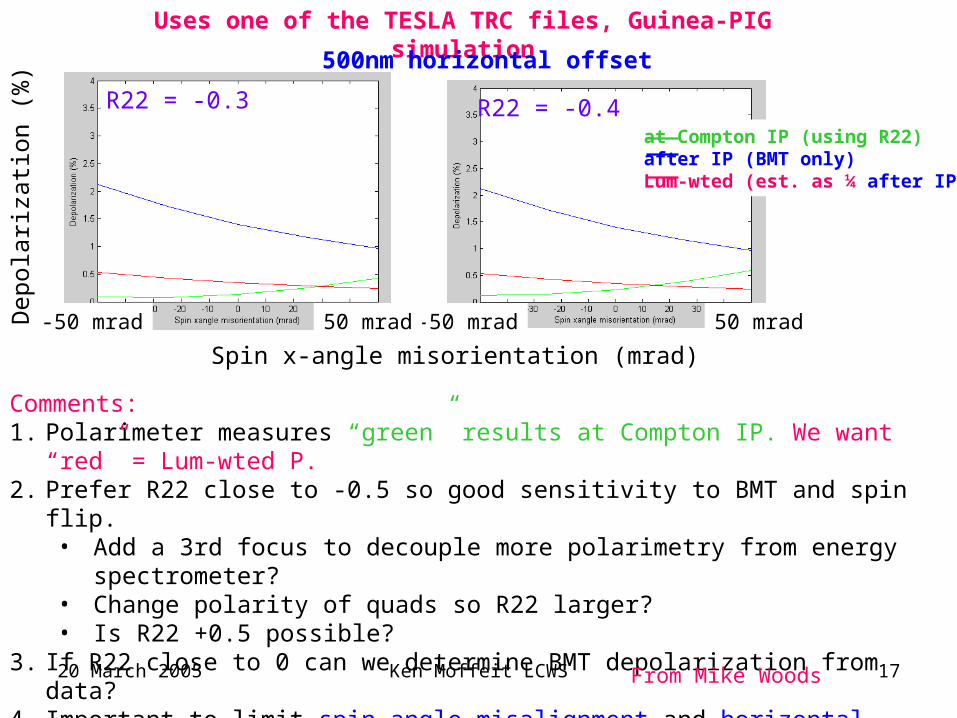
R22 = -0.3 R22 = -0.4
Comments: 1. Polarimeter measures “green” results at Compton IP. We want “red” = Lum-wted P.2. Prefer R22 close to -0.5 so good sensitivity to BMT and spin flip.
• Add a 3rd focus to decouple more polarimetry from energy spectrometer?• Change polarity of quads so R22 larger?• Is R22 +0.5 possible?
3. If R22 close to 0 can we determine BMT depolarization from data? 4. Important to limit spin angle misalignment and horizontal offsets.
• Use depolarization vs beam offset as diagnostic for spin miss-orientation at IP.
at Compton IP (using R22)after IP (BMT only)Lum-wted (est. as ¼ after IP)
Spin x-angle misorientation (mrad)
Dep
olar
izat
ion
(%)
From Mike Woods
Uses one of the TESLA TRC files, Guinea-PIG simulation
500nm horizontal offset
-50 mrad 50 mrad-50 mrad 50 mrad
20 March 2005 Ken Moffeit LCWS 18
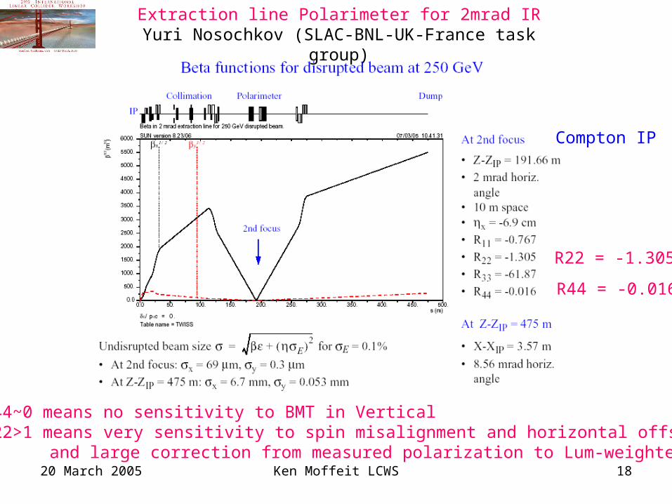
Extraction line Polarimeter for 2mrad IRYuri Nosochkov (SLAC-BNL-UK-France task group)
R44~0 means no sensitivity to BMT in VerticalR22>1 means very sensitivity to spin misalignment and horizontal offsets
and large correction from measured polarization to Lum-weighted Pol
R22 = -1.305
R44 = -0.016
Compton IP
20 March 2005 Ken Moffeit LCWS 19
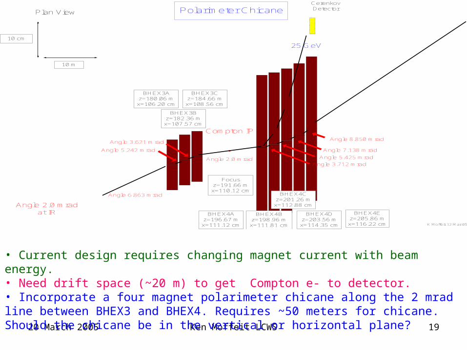
K Moffeit 12 Mar 05
Polarimeter ChicanePlan View
10 m
10 cm
BHEX3Az=180.06 mx=106.20 cm
BHEX3Bz=182.36 mx=107.57 cm
BHEX3Cz=184.66 mx=108.56 cm
BHEX4Bz=198.96 mx=111.81 cm
BHEX4Az=196.67 mx=111.12 cm
BHEX4Cz=201.26 mx=112.88 cm
BHEX4Dz=203.56 mx=114.35 cm
BHEX4Ez=205.86 mx=116.22 cm
Compton IPAngle 8.850 mrad
Angle 7.138 mrad
Angle 5.425 mrad
Angle 3.712 mradAngle 2.0 mrad
Angle 3.621 mrad
Angle 5.242 mrad
Angle 6.863 mrad
Angle 2.0 mradat IR
Focusz=191.66 mx=110.12 cm
25 GeV
CerenkovDetector
• Current design requires changing magnet current with beam energy.• Need drift space (~20 m) to get Compton e- to detector.• Incorporate a four magnet polarimeter chicane along the 2 mrad line between BHEX3 and BHEX4. Requires ~50 meters for chicane. Should the chicane be in the vertical or horizontal plane?
20 March 2005 Ken Moffeit LCWS 20
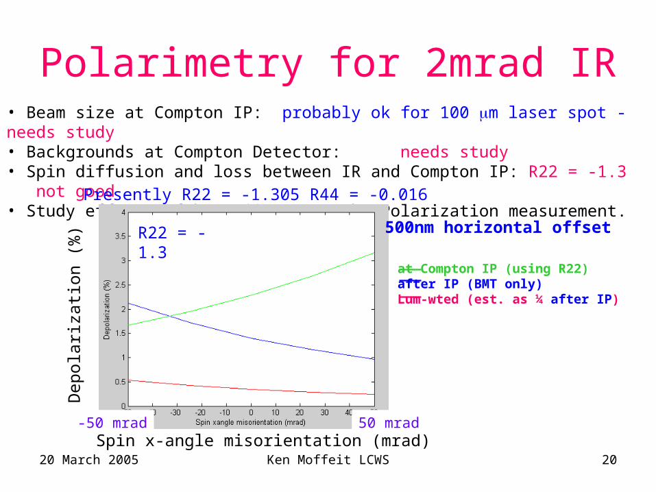
Polarimetry for 2mrad IR• Beam size at Compton IP: probably ok for 100 m laser spot - needs study• Backgrounds at Compton Detector: needs study• Spin diffusion and loss between IR and Compton IP: R22 = -1.3 not good• Study effects of beam jitter on the Polarization measurement.
R22 = -1.3
at Compton IP (using R22)after IP (BMT only)Lum-wted (est. as ¼ after IP)
Spin x-angle misorientation (mrad)
Dep
olar
izat
ion
(%)
Presently R22 = -1.305 R44 = -0.016
500nm horizontal offset
-50 mrad 50 mrad
20 March 2005 Ken Moffeit LCWS 21
SummaryBetween the damping ring at 5 GeV and the linac two parallel spin
rotation beam lines allow the spin to be tuned separately for IR1 and IR2. A set of kicker magnets activated between pulse trains is used to direct the beam into the appropriate spin rotation beam line.
Flip helicity of positron beam in input line to e+ damping ring.
Optimize 20 mrad extraction line optics for reducing systematic errors on polarization measurement.
Can polarization measurement be accomplished in extraction line for 2mrad Interaction region?– Backgrounds at Cerenkov detector need study.– Can we insert chicane along 2 mrad beam line?– Optimize optics.