Embed Size (px)
Citation preview

Note: Within nine months of the publication of the mention of the grant of the European patent in the European PatentBulletin, any person may give notice to the European Patent Office of opposition to that patent, in accordance with theImplementing Regulations. Notice of opposition shall not be deemed to have been filed until the opposition fee has beenpaid. (Art. 99(1) European Patent Convention).
Printed by Jouve, 75001 PARIS (FR)
(19)E
P2
844
865
B1
TEPZZ 844865B_T(11) EP 2 844 865 B1
(12) EUROPEAN PATENT SPECIFICATION
(45) Date of publication and mention of the grant of the patent: 27.04.2016 Bulletin 2016/17
(21) Application number: 14736591.0
(22) Date of filing: 19.06.2014
(51) Int Cl.:F02N 11/08 (2006.01) A01D 34/68 (2006.01)
F02B 63/02 (2006.01) H01M 10/052 (2010.01)
F02M 35/10 (2006.01) F02N 11/14 (2006.01)
F02N 11/10 (2006.01)
(86) International application number: PCT/US2014/043232
(87) International publication number: WO 2014/205247 (24.12.2014 Gazette 2014/52)
(54) INTERNAL COMBUSTION ENGINE INCLUDING ELECTRIC STARTING SYSTEM POWERED BY LITHIUM-ION BATTERY
BRENNKRAFTMASCHINE MIT ANHAND EINER LITHIUM-IONEN-BATTERIE BETRIEBENEM ELEKTRISCHEM STARTSYSTEM
MOTEUR À COMBUSTION INTERNE COMPRENANT UN SYSTÈME DE DÉMARRAGE ÉLECTRIQUE ALIMENTÉ PAR UNE BATTERIE AU LITHIUM-ION
(84) Designated Contracting States: AL AT BE BG CH CY CZ DE DK EE ES FI FR GB GR HR HU IE IS IT LI LT LU LV MC MK MT NL NO PL PT RO RS SE SI SK SM TR
(30) Priority: 20.06.2013 US 201361837539 P17.10.2013 US 201361892346 P
(43) Date of publication of application: 11.03.2015 Bulletin 2015/11
(73) Proprietor: Briggs & Stratton CorporationWauwatosa, WI 53222 (US)
(72) Inventors: • KOENEN, Robert
Pewaukee, WI 53072 (US)
• MARKOWSKI, MatthewWauwatosa, WI 53222 (US)
• MEYER, MichaelSussex, WI 53089 (US)
• NOMMENSEN, JamesOak Creek, WI 53154 (US)
(74) Representative: Lawrence, JohnBarker Brettell LLP 100 Hagley Road EdgbastonBirmingham B16 8QQ (GB)
(56) References cited: GB-A- 2 442 345 US-A1- 2004 257 038US-A1- 2007 240 892 US-A1- 2009 284 022US-A1- 2013 111 864

EP 2 844 865 B1
2
5
10
15
20
25
30
35
40
45
50
55
Description
BACKGROUND
[0001] The present invention generally relates to inter-nal combustion engines including electric starting sys-tems and outdoor power equipment powered by suchengines, such as lawn mowers, snow throwers, portablegenerators, etc. More specifically, the present inventionrelates to small internal combustion engines includingelectric starting systems powered by a removable, re-chargeable lithium-ion battery.[0002] Outdoor power equipment includes lawn mow-ers, riding tractors, snow throwers, pressure washers,portable generators, tillers, log splitters, zero-turn radiusmowers, walk-behind mowers, riding mowers, industrialvehicles such as forklifts, utility vehicles, etc. Outdoorpower equipment may, for example use an internal com-bustion engine to drive an implement, such as a rotaryblade of a lawn mower, a pump of a pressure washer,the auger a snowthrower, the alternator of a generator,and/or a drivetrain of the outdoor power equipment.[0003] Many pieces of outdoor power equipment in-clude engines that are manually started with a recoil start-er. To start the engine, the user must manually pull arecoil starter rope.[0004] Other pieces of outdoor power equipment in-clude electric starting systems in which a starter motorpowered by a battery starts the engine. Typically, suchelectric starting systems also include a user-actuatedstarter switch (e.g., a pushbutton or key switch) and astarter solenoid. The starter solenoid is the connectionbetween a low current circuit including the starter switchand a high current circuit including the starter motor. Tostart the engine, the user actuates the starter switch,causing the starter solenoid to close so that the batteryprovides starting current to the starting motor to start theengine.[0005] The battery is a lead-acid battery. The batteryis secured to the outdoor power equipment separate fromthe engine. For example, the battery may be secured toa mounting plate or deck of a lawn-mower or a pressurewasher or to the frame of a riding lawn mower or a port-able generator. The housing of the battery is secured tothe outdoor power equipment by fasteners that requiretools (e.g., a wrench or socket) to attach the battery tothe outdoor power equipment and to remove or loosenthe fasteners so the battery can be removed from theoutdoor power equipment. Also, the battery includes apair of terminals to which electrical leads are attached.Tools are also required to attach and remove the electri-cal leads to the terminals. Lead-acid batteries are filledwith a liquid electrolyte, typically a mixture of water andsulfuric acid. The electrolyte is corrosive. Lead-acid bat-teries are temperature sensitive, which may result in theengine having difficulty starting or not starting at all incold weather. Also, a lead-acid battery will run down withthe passage of time and not be able to provide power
(i.e., lose charge or become completely discharged). Alead-acid battery may need to be replaced seasonally,removed from the outdoor power equipment and storedinside, or otherwise maintained or serviced by a user.[0006] US2009/284,002 describes a combined batterycharging and starting circuit for portable power drivenequipment with an internal combustion engine, wherethe battery is a removable battery pack.[0007] US2013/111,864 describes a starter system foran engine. In particular, a lawn mower is described whichcomprises: an internal combustion engine; an electricmotor configured to start the internal combustion engine;a blade driven by the internal combustion engine; and anassembly for stopping at least one of the blade and theinternal combustion engine. The assembly comprises: abrake mechanism, a release mechanism, a linkage be-tween the brake mechanism and the release mechanism,an interlock configured to prevent the release mechanismfrom releasing the brake mechanism, and an interfaceallowing an operator to release the interlock. The electricmotor is coupled to the assembly such that release ofthe brake mechanism automatically engages the electricmotor to start the internal combustion engine.
SUMMARY
[0008] According to an embodiment of the invention,an internal combustion engine is set out in claim 1.[0009] Alternative exemplary embodiments relate toother features and combinations of features as may begenerally recited in the claims.
BRIEF DESCRIPTION OF THE DRAWINGS
[0010] The disclosure will become more fully under-stood from the following detailed description when takenin conjunction with the accompanying figures.
FIG. 1 is a perspective view of an internal combustionengine including an electric starting system poweredby a lithium-ion battery, according to an exemplaryembodiment of the invention.FIG. 2 is a perspective view of the engine of FIG. 1.FIG. 2A is an exploded view of the engine of FIG. 1.FIG. 3 is a top view of the engine of FIG. 1.FIG. 4 is a right-side view of the engine of FIG. 1.FIG. 5 is a rear view of the engine of FIG. 1.FIG. 6 is a perspective view of the battery receiverof the starting system of FIG. 1FIG. 7 is a detail view of a portion of the battery re-ceiver of FIG. 6.FIG. 8 is a perspective view of the battery receiverof FIG. 6.FIG. 9 is a detail view of a portion of the battery re-ceiver of FIG. 8.FIG. 10 is a left-side view of the battery receiver ofFIG. 6.FIG. 11 is a right-side view of the battery receiver of
1 2
EP 2 844 865 B1
3
5
10
15
20
25
30
35
40
45
50
55
FIG. 6.FIG. 12 is a rear view of the battery receiver of FIG. 6.FIG. 13 is a front view of the battery receiver of FIG. 6.FIG. 14 is a detail view of a portion of the batteryreceiver of FIG. 13.FIG. 15 is a top view of the battery receiver of FIG. 6.FIG. 16 is a detail view of a portion of the batteryreceiver of FIG. 15.FIG. 16A is a perspective view of a battery receiverfor a starting system, according to an exemplary em-bodiment.FIG. 17 is a perspective view of an alternative internalcombustion engine including an electric starting sys-tem powered by a lithium-ion battery.FIG. 18 is a perspective view of a further alternativeinternal combustion engine including an electricstarting system powered by a lithium-ion battery.FIG. 19 is a perspective view of a lithium-ion batteryfor use with an electric starting system of an internalcombustion engine, according to an exemplary em-bodiment of the invention.FIG. 20 is an exploded view of the lithium-ion batteryof FIG. 19.FIG. 21 is a perspective view from above of the lith-ium-ion battery of FIG. 19.FIG. 22 is a perspective view from below of the lith-ium-ion battery of FIG. 19.FIG. 23 is a perspective view from below of the lith-ium-ion battery of FIG. 19.FIG. 24 is a perspective view from below of the lith-ium-ion battery of FIG. 19.FIG. 25 is a front view of the lithium-ion battery ofFIG. 19.FIG. 26 is a rear view of the lithium-ion battery ofFIG. 19.FIG. 27 is a left-side view of the lithium-ion batteryof FIG. 19.FIG. 28 is a right-side view of the lithium-ion batteryof FIG. 19.FIG. 29 is a top view of the lithium-ion battery of FIG.19.FIG. 30 is a bottom view of the lithium-ion battery ofFIG. 19.FIG. 31 is a perspective view of a battery charger foruse with a lithium-ion battery, according to an exem-plary embodiment of the invention.FIG. 32 is a perspective of the lithium-ion battery ofFIG. 19 attached to the battery charger of FIG. 31.FIG. 33 is a schematic diagram of a starter systemfor an engine, according to an exemplary embodi-ment of the invention.FIG. 34 is a schematic diagram of a starter systemfor an engine, according to an exemplary embodi-ment of the invention.FIG. 35 is a schematic diagram of a starter systemfor an engine, according to an exemplary embodi-ment of the invention.FIG. 36 is a schematic diagram of a starter system
for an engine, according to an exemplary embodi-ment of the invention.FIG. 37 is a circuit diagram of a control system for abattery, according to an exemplary embodiment ofthe invention.FIG. 38 is perspective view from above of a blowerhousing according to an exemplary embodiment.FIG. 39 is a perspective view from below of the blow-er housing of FIG. 22.FIG. 40 is another perspective view from below ofthe blower housing of FIG. 22.FIG. 41 is a perspective view of a lawn mower, ac-cording to an exemplary embodiment.FIG. 42 is a schematic diagram of a starter systemfor an engine, according to an exemplary embodi-ment.FIG. 43 is a perspective view of components of astarter system for outdoor power equipment accord-ing to an exemplary embodiment.FIG. 44 is a perspective view of an engine assembly,according to an exemplary embodiment.FIG. 45 is a perspective view of a battery chargingstation, according to an exemplary embodiment.FIG. 46 is a perspective view of a battery being cou-pled to an engine, according to an exemplary em-bodiment.FIG. 47 is a perspective view of a starter system forthe engine assembly of FIG. 44, according to an ex-emplary embodiment.FIG. 48 is a front view of a battery for a starter system,according to an exemplary embodiment.FIG. 49 is a top view of the battery of FIG. 48.FIG. 50 is a bottom view of the battery of FIG. 48.FIG. 51 is a left side view of the battery of FIG. 48.FIG. 52 is a right side view of the battery of FIG. 48.FIG. 53 is a bottom view of the battery of FIG. 48with a portion of the housing removed to show theinterior of the battery.FIG. 54 is a front view of a battery receiver for astarter system, according to an exemplary embodi-ment.FIG. 55 is a top view of the receiver of FIG. 54.FIG. 56 is a bottom view of the receiver of FIG. 54.FIG. 57 is a cross-section view of the receiver of FIG.54, taken along line 57-57.FIG. 58 is a cross-section view of the receiver of FIG.54, taken along line 58-58.FIG. 59 is a perspective view of a pressure washeraccording to an exemplary embodiment.FIG. 60 is a circuit diagram for a starter system ofan engine according to another exemplary embodi-ment of the invention.
DETAILED DESCRIPTION
[0011] Before turning to the figures, which illustrate theexemplary embodiments in detail, it should be under-stood that the present application is set out in the claims,
3 4

EP 2 844 865 B1
4
5
10
15
20
25
30
35
40
45
50
55
and is not limited to the details or methodology set forthin the description or illustrated in the figures.[0012] Internal combustion engines including electricstarting systems powered by a removable, rechargeablelithium-ion battery, as described herein, provide numer-ous advantages over engines that are manually startedand engines including electric start systems powered bya lead-acid battery. Electric starting systems eliminatethe need for a manual recoil starter and the need for theuser to pull the starter rope to start the engine. Using aremovable, rechargeable lithium-ion battery to power theelectric starting system eliminates many of the hassles,inconveniences, and shortcomings of systems poweredby the lead-acid batteries. As described herein, the lith-ium-ion battery is removable from a battery receiver with-out the use of tools. The relatively lightweight lithium-ionbattery is easily attached to and removed from the batteryreceiver by hand. This is greatly simplified from the proc-ess of removing a lead-acid battery from a piece of out-door power equipment. A user must safely disconnectthe electrical leads connected to the terminals of the lead-acid battery, which requires the use of tools. The lead-acid battery must then be removed from its mountinglocation, typically a frame, plate, or other mounting loca-tion separate from the engine. This also requires the useof tools. In several preferred embodiments, the batteryreceiver is a component of the engine itself so the lithium-ion battery is mounted to the engine, rather than a loca-tion remote from the engine like a lead-acid battery wouldbe. Systems using lead-acid batteries may have the lead-acid battery covered or otherwise out of sight (e.g., underthe seat of a riding tractor), requiring the user to removeor move components to access the lead-battery, anotherstep which may require the use of tools. The ease ofremoving the lithium-ion battery makes it easier to limitthe battery’s exposure to cold temperatures than a lead-acid battery (e.g., on a piece of outdoor power equipmentstored in a garage during winter). A user can easily re-move the lithium-ion battery and store it in a heated lo-cation (e.g., inside the user’s home), or keep a secondlithium-ion battery in a heated location so that the secondlithium-ion battery is available for use if cold temperaturesare affecting the operation of the first lithium-ion battery.Disconnecting, removing, reinstalling, and reconnectinga lead-acid battery using tools in similar cold weatheroperating conditions is a burdensome task not done bya typical user. Also, for pieces of outdoor power equip-ment used seasonally (e.g., lawn mowers and pressurewashers in warm months and snow throwers in coldmonths), a lead-acid battery may be run down, dead, orotherwise at a level of charge insufficient to start the en-gine after a season of not being used (e.g., starting alawn mower for the first time after winter). A user caneither store the lithium-ion battery indoors on the batterycharger, keeping it both charged and at an appropriateoperating temperature or easily remove the lithium-ionbattery from the battery receiver without the use of tools,quickly recharge it in the battery charger, and reattach it
to the battery receiver without the use of tools to powerthe electric starting system and start the engine of theoutdoor power equipment.[0013] The lithium-ion battery described herein re-charges quickly even when completely depleted ofcharge. In tests, a lithium-ion battery as described hereincompletely depleted of charge was charged for oneminute and was able to provide power sufficient to twicestart the engine to which it was subsequently attached.The lithium-ion battery as described herein can be fullycharged in sixty minutes and at full charge can providefifty starts or more of an engine. The lithium-ion batteryas described herein is able to provide more than ten startsof an engine after ten minutes of charging.[0014] The lithium-ion battery described herein elimi-nates concerns related to the corrosive electrolyte of alead-acid battery, simplifying handling of the battery bythe user.[0015] The ability to install the lithium-ion battery with-out the use of tools and including the battery receiver asa component of the engine itself simplifies assembly ofthe engine into a piece of outdoor power equipment byan original equipment manufacturer ("OEM"). There isno need for the OEM to use tools to attach the lithium-ion battery to the outdoor power equipment, unlike witha lead-acid battery, and also no need to use tools to con-nect electrical leads to the terminals of the battery. Also,fewer parts may be required. For example, the wiringharness including the electrical leads attached to thelead-acid battery may be eliminated or simplified in itsdesign and/or routing.[0016] The ease of removing and recharging the lithi-um-ion battery as described herein also increases end-user comfort with outdoor power equipment not includinga manual starting system (e.g., a recoil starter). Becausethe lithium-ion battery is easily removed without tools andquickly recharged to a charge state sufficient to start theengine, the end user can be confident in being able tostart the engine in most circumstances (e.g., absent anyissues with the starting system and other engine compo-nents other than a dead battery). In preferred embodi-ments, the lithium-ion battery described herein includesa display that visually indicates to the user the battery’slevel of charge. An electrical starting system powered bya lead-acid battery that is not able to start the engine canbe incredibly frustrating for the end user (e.g, becausethe lead-acid battery has insufficient charge to start theengine). There is no quick and easy way to determinethe level of charge in the lead-acid battery and, if neces-sary, no quick and easy way to replace or recharge thelead-acid battery. A depleted lead-acid battery needs tobe disconnected from the electrical leads with tools, re-moved from the outdoor power equipment with tools, andbe properly disposed of. The end user then must acquirea new lead-acid battery, almost certainly needing to takea trip to the store to do so, install the new lead-acid batterywith tools, and connect the electrical leads to the newlead-acid battery with tools.
5 6

EP 2 844 865 B1
5
5
10
15
20
25
30
35
40
45
50
55
[0017] Referring to FIGS. 1-5, an internal combustionengine 1000 is illustrated according to an exemplary em-bodiment. The internal combustion engine 1000 includesan engine block 1002 having a cylinder 1004, a piston1006, and a crankshaft 1008. The piston 1006 recipro-cates in the cylinder 1004 along a cylinder axis 1010 todrive the crankshaft 1008. The crankshaft 1008 rotatesabout a crankshaft axis 1012. As shown in FIG. 2A, theengine 1000 includes fuel system 1001 for supplying anair-fuel mixture to the cylinder 1004 (e.g., a carburetor,an electronic fuel injection system, etc.), an air filter as-sembly 1003, a cylinder head assembly 1005, a mufflerassembly 1007, a fuel tank assembly 1009, and a fly-wheel and fan assembly 1011. In the illustrated embod-iment, the cylinder 1004 and the cylinder axis 1010 areoriented horizontally (i.e., a horizontal cylinder engine).In some embodiments, the cylinder 1004 and the cylinderaxis 1010 can be oriented vertically (i.e., a vertical cylin-der engine) or at an angle (i.e., a slanted engine). In someembodiments, the engine includes multiple cylinders, forexample, a two cylinder engine arranged in a V-twin con-figuration.[0018] The engine 1000 also includes an electric start-ing system 1014. The electric starting system 1014 in-cludes a starter motor 1016, a battery receiver 1018, anda removable, rechargeable lithium-ion battery 1020. Thestarter motor 1016 is electrically coupled to the lithium-ion battery 1020 to be powered by the lithium-ion battery1020. When activated in a response to a user input (e.g.,via a key switch, a push button, a bail start system, atrigger start system for a pressure washer, other auto-matic start system, etc.), the starter motor 1016 rotatesthe crankshaft 1008 to start the engine. The starter motor1016 is selectively coupled to the crankshaft 1008 (e.g.,by a movable pinion gear that selectively engages a fly-wheel ring gear) so that the starter motor 1016 may bedecoupled from the crankshaft 1008 (i.e., does not rotatewith the crankshaft 1008 after the engine 1000 has beensuccessfully started). As illustrated, the starter motor1016 is attached to the engine block 1002.[0019] Referring to FIGS. 6-18, the battery receiver1018 is illustrated according to an exemplary embodi-ment. The battery receiver 1018 includes a receptacle1022 (port, socket, pocket, etc.) configured to receive thelithium-ion battery 1020. The receptacle 1022 includesthree male terminals 1024, 1026, and 1028 configuredto couple with corresponding female terminals of the lith-ium-ion battery 1020. The receptacle 1022 includes asecond set of three male terminals 1030, 1032, and 1034configured to be coupled to corresponding terminals ofa wiring harness, which is electrically coupled to the start-er motor and any other electrical components of the en-gine 1000 and/or the piece outdoor power equipment in-cluding the engine that are powered by or send signals(data, information, etc.) to and/or from the lithium-ion bat-tery 1020. Each of the terminals 1024, 1026, and 1028is electrically coupled to a corresponding one of the ter-minals 1030, 1032, and 1034. Two pairs of the terminals
(e.g., terminal pair 1024 and 1030 and terminal pair 1028and 1034) are used to complete an electrical circuit be-tween the starter motor 1016 and the lithium-ion battery1020 (e.g., as a positive terminal pair and a ground ter-minal pair). These two pair of terminals may be referredto as voltage output terminals. The third pair of the ter-minals (e.g., terminal pair 1026 and 1032) is used totransmit a signal (e.g., an enable signal as describedherein) to and/or from the lithium-ion battery 1020. Thisthird pair of terminals may be referred to as data terminalsor as the enable terminals. A guide 1036 (wall, protrusion,etc.) is positioned on either side of each of the terminals1024, 1026, and 1028. Each guide 1036 is received bya corresponding aperture in the lithium-ion battery andhelps to guide the terminals 1024, 1026, and 1028 intothe corresponding female terminals of the lithium-ion bat-tery 1020. The guides 1036 extend outward from a wall1038 of the receptacle 1022 to a distance greater thanthat of the terminals 1024, 1026, and 1028. The enableterminal 1026 extends to a distance less than the voltageoutput terminals 1024 and 1028. This helps to ensurethat lithium-ion battery 1020 is not able to power the start-er motor 1016 except when the lithium-ion battery 1020is properly secured (fully inserted, fully seated, properlyinserted, properly seated, properly installed) in the re-ceptacle 1022. Unless the lithium-ion battery 1020 isproperly secured, the lithium-ion battery 1020 cannot pro-vide power to the starter motor 1016, even with the volt-age output terminals 1024 and 1028 electrically connect-ed to corresponding voltage output terminals of the lith-ium-ion battery 1020. The lack of connection to the en-able terminal 1026 prevents an enable signal needed forthe lithium-ion battery 1020 to provide power to the startermotor 1016 from reaching the lithium-ion battery 1020.[0020] The receptacle 1022 is defined by a floor 1040,sidewalls 1042, and an end wall 1044. The receptacle1022 is open on one end 1046 to allow the lithium-ionbattery 1020 to be slid into the receptacle 1022 from theside. The sidewalls 1042 are connected by the end wall1044. A protrusion or rail 1048 extends inward from eachsidewall 1042 and is sized to be received by a corre-sponding slot in the lithium-ion battery 1020. Each rail1048 extends forward from the end wall 1044 toward theopen end 1046.[0021] The sidewalls 1042 may each include an angledend portion 1050 proximate the open end 1046 such thatthe open end 1046 has a width that is greater than thewidth of the lithium-ion battery 1020 and of the remainderof the receptacle 1022. The angled end portions 1050facilitate the insertion of the lithium-ion battery 1020 intothe receptacle 1022 through the open end 1046. Theangled end portions 1050 also provide access for a userto actuate the push buttons found on the sides of thelithium-ion battery 1020.[0022] The floor 1040 is an offset body that includesthe wall 1038 (a vertical step or shoulder). The wall 1038may contact a corresponding wall of the lithium-ion bat-tery 1020 to limit the travel of the lithium-ion battery 1020
7 8

EP 2 844 865 B1
6
5
10
15
20
25
30
35
40
45
50
55
relative to the receiver 1018. The wall 1038 separatestwo portions of the floor 1040, the upper portion 1052and the lower portion 1054. The lower portion 1054 in-cludes a latching region 1056 (strike plate, latching por-tion, locking region, locking portion) configured to receivea corresponding latch of the lithium-ion battery 1020 tosecure the lithium-ion battery to the battery receiver1018. The latching region 1056 includes apertures 1058that each are configured to receive and correspond to aprotrusion of the latch of the lithium-ion battery 1020.[0023] In some embodiments, the receptacle 1022 isconfigured to protect the terminals 1024, 1026, and 1028from environmental hazards. For example, the floor 1040may slope away from the terminals 1024, 1026, and 1028to direct moisture away from the terminals 1024, 1026,and 1028. According to other exemplary embodiments,the terminals may be oriented horizontally or the termi-nals of the battery may be vertical and interface with ter-minals provided in an elevated portion of the receiversuch that any moisture that enters the space betweenthe battery and the receiver flows away from the termi-nals. The battery receiver 1018 and/or other portions ofthe engine 1000 proximate the receptacle 1022 may in-clude features (e.g., channels, drain holes, weep holes,sloped surfaces, etc.) that direct moisture and debrisaway from the terminals 1024, 1026, and 1028.[0024] As illustrated, the battery receiver 1018 is a por-tion of an engine housing 1060 (blower housing, cowl,cover, etc.) The battery receiver 1018 includes an airintake 1062. The air intake 1062 includes multiple aper-tures 1064 (openings, slots, etc.) that allow air to enterthe engine housing (e.g., air drawn into the engine hous-ing by a flywheel or blower fan for use to air cool theengine). The apertures 1064 also limit the ability for de-bris such as grass clippings to pass through the air intake1062. As illustrated, the battery receiver 1018 is formedas a generally dome-shaped body that is configured asa cover or screen of the engine. The battery receiver1018 may be separate from a base 1066 (remainder) ofthe engine housing 1060. As illustrated, the battery re-ceiver 1018 is secured to the base 1066 by threadedfasteners. In other embodiments, for example as illus-trated in FIG. 16A, the battery receiver 1018 is integrallyformed (e.g., molded) with the base 1066 of the enginehousing 1060.[0025] As illustrated, the battery receiver 1018 is posi-tioned relative to the rest of the engine 1000 at the loca-tion typically occupied by a recoil starter in a manually-started engine. With this positioning, the electric startingsystem 1014 replaces the recoil starter in a way that isintuitive to the user by placing the battery receiver 1018and the lithium-ion battery 1020 in the location where theuser expects to find the equipment (i.e., the recoil starter)used to start a typical manually-started engine. This po-sitioning places the battery receiver 1018 above thecrankshaft 1008 with the crankshaft axis 1012 extendingthrough a portion of the battery receiver 1018. The fly-wheel is located below the battery receiver 1018. Elimi-
nating the recoil starter reduces the engine operatingtemperature (e.g., the oil temperature) by improving airflow into the cooling system (e.g., the blower housing).For example, replacing the recoil starter with the batteryreceiver 1018 and the lithium-ion battery 1020 can re-duce the engine operating temperature by between 10and 20 degrees Fahrenheit (5.6 degrees and 11.1 de-grees Celsius) in expected operating conditions. Reduc-ing the engine operating temperature can help to reduceoil deterioration, overheating, and other failure modesrelated to high temperatures. In other embodiments, thereceptacle 1022 is incorporated into a battery receiverhaving a different shape or form appropriate to the mount-ing location for that receiver relative to the other compo-nents of the engine 1000. For example, the battery re-ceiver for a horizontally-shafted single-cylinder engine orfor a two-cylinder engine may be located at a differentportion of the engine housing than the vertically-shaftedsingle-illustrated engine 1000 as shown. Referring toFIG. 17, a horizontally-shafted single-cylinder internalcombustion engine 3000 is illustrated as an alternativeexample. The lithium-ion battery 1020 is selectively at-tached to a battery receiver 3018. As illustrated, the bat-tery receiver 3018 is a portion of the engine housing 3060.Referring to FIG. 18, a V-twin two-cylinder internal com-bustion engine 4000 is illustrated according to anotherexample. The lithium-ion battery 1020 is selectively at-tached to a battery receiver 4018. As illustrated, the bat-tery receiver 4018 is a portion of the engine housing 4060.In other examples, the battery receiver isnot a component of the engine itself and is instead mount-ed to the outdoor power equipment at a location remotefrom (separate from, spaced apart from), the engine1000. An electrical connection (e.g., a wiring harness) isused to electrically connect such a battery receiver to thestarter motor 1016 and any other required electrical com-ponents of the outdoor power equipment. For example,for a riding tractor, riding lawn-mower, snow thrower, orzero-turn mower, the battery receiver may be a compo-nent of a dashboard or other user-control panel.[0026] Referring to FIGS. 19-30, the lithium-ion battery1020 is illustrated according to an exemplary embodi-ment. The lithium-ion battery 1020 is not equivalent to alithium-ion battery for use with cordless power tools (e.g.,a drill). For example, the lithium-ion battery 1020 mayinclude fewer lithium-ion battery cells than a power toolbattery and is intended for less frequent cycling at lowerrun times than a power tool battery (e.g., used to start anengine, not used to power frequent running of a drill motorfor relatively long durations). The operation of the lithium-ion battery 1020 requires an output of relatively high cur-rent (e.g., 200 Amps) over a relatively short dischargetime (e.g., 10 milliseconds). A lithium-ion battery for usewith a power tool or portable computing device (e.g., alaptop computer) provides an output of a relatively lowcurrent over a relatively long discharge time. Additionally,a power tool lithium-ion battery is "always on" so that itis always able to provide power to the tool. In a preferred
9 10

EP 2 844 865 B1
7
5
10
15
20
25
30
35
40
45
50
55
embodiment described in more detail below, the lithium-ion battery 1020 is only on when it is receiving an enableinput indicating a need to start the engine. Without theenable input, the lithium-ion battery 1020 does not pro-vide any power to the electric starting system 1014. Thisallows the lithium-ion battery 1020 to be removed fromthe receptacle 1022 after the engine 1000 is successfullystarter. For example, a user could start the engine 1000with a lithium-ion battery 1020 having a relatively lowcharge and then remove and recharge the lithium-ionbattery 1020 while using the outdoor power equipment.In a preferred embodiment, the lithium-ion battery 1020is rated at 10.8 Volts (V) and 1.5 Amp-hours (Ah).[0027] As shown in FIG. 20, the lithium-ion battery1020 includes one or more lithium-ion cells 1068 electri-cally coupled together. As illustrated, three lithium-ioncells 1068 are used, though more or fewer may be usedin different embodiments. Each lithium-ion cells 1068 isformed as an elongated body having a longitudinal axis(e.g., a cylindrical, cylinder, or cylindrical roll style lithium-ion cells). All three lithium-ion cells 1068 are oriented inthe same direction, the cell axis 1070. The three lithium-ion cells 1068 are secured as a pack 1072 so that theentirety of the pack 1072 (including all three lithium-ioncells 1068) moves as a single integral unit. This preventsthe three lithium-ion cells 1068 from moving independ-ently to one another. Movement of the pack 1072 as asingle unit helps to reduce failure modes for the lithium-ion battery 1020 related to vibration, as will be explainedin more detail herein.[0028] The lithium-ion battery 1020 also includesprocessing electronics 1074 (controller, processing cir-cuit, etc.) In a preferred embodiment, the processingelectronics 1074 includes a processor 1076 (microproc-essor) and a memory device 1078. The processor 1076can be implemented as a general purpose processor, anapplication specific integrated circuit (ASIC), one or morefield programmable gate arrays (FPGAs), a group ofprocessing components, or other suitable electronicprocessing components. The memory device 1078 (e.g.,memory, memory unit, storage device, etc.) is one ormore devices (e.g., RAM, ROM, Flash memory, hard diskstorage, etc.) for storing data and/or computer code forcompleting or facilitating the various processes, layersand modules described in the present application. Thememory device 1078 may be or include volatile memoryor non-volatile memory. The memory device 1078 mayinclude database components, object code components,script components, or any other type of information struc-ture for supporting the various activities and informationstructures described in the present application. Accord-ing to an exemplary embodiment, The memory device1078 is communicably connected to processor viaprocessing circuit and includes computer code for exe-cuting (e.g., by processing circuit and/or processor) oneor more processes described herein. In a preferred de-vice, the processing electronics 1074 implements one ormore processes to protect the lithium-ion battery 1020
(e.g., prevents operation outside of a range of appropri-ate operating temperatures), to optimize performance ofthe lithium-ion battery 1020, and to optimize the life ofthe lithium-ion battery 1020.[0029] The lithium-ion battery 1020 further includes adisplay 1080 for providing information to a user. In theillustrated embodiment, the display 1080 consists of fourlight sources 1082. In a preferred embodiment, each lightsource 1082 is a light-emitting diode (LED). In other em-bodiments, more or fewer light sources may be included.In other embodiments, the display 1080 is a LCD or otherappropriate display screen. In some embodiments, anaudible device (e.g, a speaker) is used in addition to orin place of the display 1080 to provide information to auser. A user interface 1084 (e.g., a pushbutton, switch,button, touchscreen, etc.) is actuated by the user to ac-tivate the display 1080. Once activated, the display 1080provides a battery charge level indication to the user byturning on one or more of the light sources 1082. In someembodiments, the display 1080 is deactivated after a pre-determined amount of time passes after the user actu-ates the user interface 1084. In other embodiments, thedisplay 1080 is only activated while the user interface1084 is actuated. In a preferred embodiment, all four lightsources 1082 being lit indicates more than 78% chargelevel, three lights sources 1082 being lit indicates morethan 55% charge level, two light sources 1082 being litindicates more than 33% charge level, one light source1082 being lit indicates more than 10% charge level, oneblinking or flashing light source 1082 indicates less than10% charge level, and all four light sources 1082 blinkingor flashing indicates an error (e.g., an overcurrent state).In some embodiments, the display 1080 is omitted.[0030] A battery housing 1086 contains and supportsthe lithium-ion cells 1068 and the processing electronics1074. The housing 1086 also supports the display 1080and the user interface 1084. As illustrated, the housing1086 is formed by two primary pieces, a top half or portion1088 and a bottom half or portion 1090, though otherconstructions are possible. The housing 1086 has a topside 1092, a bottom side 1094, a front side 1096, a backside 1098, a left side 1100, and a right side 1102. Theoverall dimensions of the housing 1086 correspond tothose of the receptacle 1022 so that the lithium-ion bat-tery 1020 can be received by the receptacle 1022 andattached to the battery receiver 1018. In a preferred em-bodiment, the housing 1086 is a sealed enclosure thatis configured to protect the electrochemical cells by pre-venting environmental contaminants (e.g., moisture,plant debris, salt, dust, etc.) from passing into the interiorof the housing 1086. The housing 1086 provides a ruggedstructure that is able to withstand impact during operationof the outdoor power equipment (e.g., impacts frombranches or trunks when operating a lawn mower). Thehousing 1086 can be formed from a material that is re-sistant to liquid or vaporized fuel (e.g., polyethyleneterephthalate or PET) to prevent fuel from passing intothe interior of the housing 1086.
11 12
EP 2 844 865 B1
8
5
10
15
20
25
30
35
40
45
50
55
[0031] An aperture or slot 1104 is formed in the leftside 1100 and the right side 1102 proximate the backside 1098. The slots 1104 include an open end at theback side 1098 and an opposite closed end. Each slot1104 is sized to receive the corresponding rail 1048 ofthe receptacle 1022. Contact between the closed end ofthe slots 1104 and the corresponding ends of the rails1048 functions as a stop to limit the travel of the lithium-ion battery 1020 into the receptacle 1022.[0032] As shown in FIGS. 24, 26-28, and 30, the bottomside 1094 of the housing 1086 is an offset body that mir-rors the floor 1040 of the receptacle 1022. The bottomside 1094 includes an upper portion 1106 and a lowerportion 1108 separated by a wall 1110. Contact betweenthe wall 1110 of the lithium-ion battery 1020 and the cor-responding wall 1038 of the receptacle 1022 functionsas a stop to limit the travel of the lithium-ion battery 1020into the receptacle 1022.[0033] A latch 1112 (lock, locking member, latchingmember) is pivotally coupled to the housing 1086. Asshown in FIG. 23, in a latched position (secured, locked,engaged, extended etc.), a latching portion 1114 of thelatch 1112 extends through an aperture 1116 (opening)through the bottom side 1094 of the housing 1086 andis retracted through the aperture 1116 into the interior ofthe housing 1086 in a release position (unlatched, unse-cured, unlocked, disengaged, retracted, etc.). A bodyportion 1118 of the latch 1112 (FIG. 20) remains in theinterior of the housing 1086. The latch 1112 is mechan-ically coupled to a pair of push buttons, a right push button1120 and a left push button 1122. Each push button ex-tends through an aperture in a corresponding side of thehousing. The push buttons 1120 and 1122 are biasedoutward from the interior of the housing 1086 to an ex-tended position (secured, locked, engaged, latched, etc.)A spring 1124 or other biasing member or biasing mem-bers bias the push buttons 1120 and 1122 to the extend-ed position. As shown in FIG. 24, the push buttons 1120and 1122 are movable inward toward the interior of thehousing 1086 to a depressed position (retracted, re-leased, unsecured, unlocked, disengaged, etc.). The me-chanical coupling between the push buttons 1120 and1122 is such that the push buttons being in the extendedposition causes the latch 1112 to be in the latched posi-tion (FIG. 23) and moving both push buttons 1120 and1122 to the depressed position causes the latch 1112 tobe in the release position (FIG. 24). This mechanical cou-pling also causes the spring 1124 to bias the latch 1112to the latched position. The push buttons 1120 and 1122are able to move separately from one another, but eachpush button 1120 and 1122 must be in its depressedposition for the latch to completely be in the release po-sition. This arrangement helps to avoid accidental un-latching (unsecuring, release, unlocking, etc.) of the lith-ium-ion battery 1020 from the receptacle 1022 when onlyone of the push buttons 1120 and 1122 is depressed.This helps to prevent the lithium-ion battery 1020 fromunwanted unlatching when impacted by an object or ob-
stacle (branch, trunk, wall, shrub, rock, etc.) when in useon a piece of outdoor power equipment because it is un-likely that both push buttons 1120 and 1120 will be si-multaneously actuated by an unwanted impact with anobject of obstacle when using the outdoor power equip-ment. The latching portion 1114 includes one or moreprotrusions, as illustrated a transverse wall 1126 andthree legs 1128 that extend substantially perpendicularto the wall 1126.[0034] Four female terminals 1130, 1132, 1134, and1136 are located within the bottom side 1094 of the hous-ing 1086. The female terminals 1130, 1132, 1134, and1136 are configured to couple with the correspondingmale terminals of a receptacle, for example male termi-nals 1024, 1026, and 1028 of the receptacle 1022 of thebattery receiver 1018 or male terminals of the receptacleof a battery charger.[0035] A pair of the terminals (e.g., terminals 1130 and1134) are used to complete an electrical circuit betweenthe starter motor 1016 and the lithium-ion battery 1020(e.g., as a positive terminal and a ground terminal). Thispair of terminals may be referred to as voltage outputterminals. The other two terminals (e.g., terminals 1132and 1136) may each be used to transmit a signal (e.g.,an enable signal as described herein) to and/or from thelithium-ion battery 1020. This second pair of terminalsmay be referred to as data terminals. In particular, oneof the terminals (e.g., terminal 1132) may be referred toas the enable terminal and is used to receive an enableinput signal as described herein. In a preferred embodi-ment, each of the female terminals 1130, 1132, 1134,and 1136 is formed as a pair of opposed springs thatreceive and hold a male terminal of the lithium-ion battery1020. The opposed springs exert opposing forces trans-verse to the longitudinal axis of the male terminal, whichhelps to reduce wear of the male terminals and make asecure electrical connection between the female terminaland the male terminal.[0036] The terminals 1130, 1132, 1134, and 1136 arepositioned within slots or apertures 1140 formed in thebottom side 1094. Each aperture 1140 has an open endin the wall 1110 and an open end in the upper portion1106 and is sized to receive a corresponding male ter-minal. Additional apertures 1142 are formed in the bottomside, each with an open end in the wall 1110 and an openend in the upper portion 1106. Each aperture 1142 issized and positioned to receive one of the guides 1036of the receptacle 1022. The interaction between the ap-ertures 1142 and the guides 1036 help to guide the lith-ium-ion battery 1020 into the receptacle 1022 and ensureproper connections between the male terminals of thereceptacle 1022 and the female terminals of the lithium-ion battery 1020.[0037] In alternative embodiments, the lithium-ion bat-tery 1020 can include a few as two male terminals (i.e.,two voltage output terminals) or more than four male ter-minals. In some embodiments, two pairs of terminals areconfigured as voltage output terminals. For example, the
13 14

EP 2 844 865 B1
9
5
10
15
20
25
30
35
40
45
50
55
first pair of voltage output terminals could provide a volt-age (e.g., 10 V) sufficient to start the starter motor 1016and the second pair of voltage output terminals couldprovide a voltage (e.g., 3 V) sufficient to power one ormore other electric components of the engine 1000 orthe outdoor power equipment powered by the engine1000 (e.g., a light source or processing electronics). Asanother example, the first pair of voltage output terminalscould provide a voltage (e.g., 12 V) sufficient to start thestarter motor 1016 and be grouped with an enable ter-minal to control activation of the lithium-ion battery 1020and the second pair of voltage output terminals couldprovide a continuous voltage (e.g., 12 V) not dependenton the state of the enable signal to the enable terminalto power one or more electronic components of the en-gine 1000 or the outdoor power equipment powered bythe engine 1000 other than starter motor 1016.[0038] According to other exemplary embodiments,the lithium-ion battery 1020 may further include additionalports or connectors. For example, the battery may in-clude a universal serial bus (USB) port that may be usedas an input to receive power to charge the lithium-ioncells 1068 or as an output to power or charge anotherdevice (e.g., a mobile phone, etc.) from the lithium-ioncells 1068.[0039] To attach the lithium-ion battery 1020 to the bat-tery receiver 1018, the user slides the lithium-ion battery1020 back side first into the receptacle 1022 through theopen end 1046. The front end of each rail 1048 is receivedin the corresponding slot 1104 of the lithium-ion battery1020, helping to guide the lithium-ion battery 1020 intothe receptacle 1022 and to position the lithium-ion battery1020 within the receptacle 1022. Each of the apertures1142 of the lithium-ion battery 1020 then receive the cor-responding guide 1036 of the receptacle, further helpingto guide the lithium-ion battery 1020 into the receptacleand positioning the female terminals 1130, 1132, and1134 of the lithium-ion battery 1020 to receive the maleterminals 1024, 1026, and 1028 of the receptacle 1022.The voltage output terminals 1024 and 1130 and 1028and 1134 are electrically connected before the enableterminals 1026 and 1132. Contact between the wall 1038of the receptacle 1022 and the wall 1110 of the lithium-ion battery and contact between the front ends of the rails1048 of the receptacle 1022 and the closed ends of theslots 1104 of the lithium-ion battery 1020, and contactbetween the end wall 1044 of the receptacle 1022 andthe back side 1098 of the lithium-ion battery 1020 stop(limit, halt) insertion of the lithium-ion battery 1020 intothe receptacle 1022 and align the latch 1112 of the lith-ium-ion battery 1020 and the latching region 1056 of thereceptacle 1022. When these points of physical contactbetween the lithium-ion battery 1020 and the receptacleare made, the lithium-ion battery 1020 is properly se-cured (fully inserted, fully seated, properly inserted, prop-erly seated, properly installed) in the receptacle 1022.These points of physical contact between the lithium-ionbattery 1020 and the receptacle 1022 and the longitudinal
dimensions of the enable terminals 1026 and 1132 arearranged so that the enable terminals 1026 and 1132 arenot electrically connected unless these points of physicalcontact are made between the lithium-ion battery 1020and the receptacle 1022, thereby preventing the lithium-ion battery 1020 from powering the starter motor 1016because the lithium-ion battery 1020 cannot receive theenable signal. The latch 1112 is biased to latched positionto automatically engage the latching region 1056, therebyattaching (securing, locking) the lithium-ion battery 1020to the battery receiver 1018. In some embodiments, thelatch 1112 engages the latching region 1056 with an au-dible sound (e.g., a "click"). With the latch 1112 in thelatched position, the latching portion 1114 engages thelatching region 1056 of the receptacle 1022 to attach thelithium-ion battery 1020 to the battery receiver 1018. Inthe latched position of the latch 1112, the wall 1126 andlegs 1128 of the latching portion 1114 are received bycorresponding apertures 1058 of the latching region1056. In the release position of the latch 1112, the wall1126 and the legs 1128 are moved out of the apertures1058, unattaching (unsecuring, unlocking, releasing, dis-engaging) the lithium-ion battery 1020 from the batteryreceiver 1018 and allowing the lithium-ion battery 1020to be removed from the receptacle 1022 by reversing theabove steps. The latch 1112 is moved to the release po-sition by moving each push button 1120 and 1122 to itsdepressed position. In this way, the lithium-ion battery1020 is removably attached to the battery receiver 1018and the push buttons 1120 and 1122 and latch 1112 allowa user to selectively attach and remove the lithium-ionbattery 1020 to the battery receiver 1018 without the useof tools.[0040] Vibrations caused by the operation of an engineand the operation of the piece of outdoor power equip-ment that the engine powers can potentially cause theloss of the electrical connections between one or moreof the terminals of the lithium-ion battery 1020 and theterminals of the receptacle 1022. These vibrations canalso potentially damage the lithium-ion cells 1068 or othersensitive components of the lithium-ion battery 1020 orthe battery receiver 1018. These possible negative ef-fects caused by vibrations inherent in the operation ofthe engine and the outdoor power equipment that theengine powers can be reduced by selecting an appropri-ate orientation of the cell axis 1070 of a lithium-ion battery1020 attached to the battery receiver 1018. This cell axisorientation is dependent on the orientation of the recep-tacle 1022 of the battery receiver 1018. To reduce thepossible negative effects caused by vibrations, the cellaxis 1070 should not be parallel to (in the same direction)an axis representative of the primary direction of vibra-tions of the engine or vibrations of the piece of outdoorpower equipment to which the engine will be attached(i.e., a primary vibration axis). The vibrations of the en-gine or the outdoor power equipment will likely not bepurely linear in a single direction. However, analyzing thevibrations of the engine or the specific piece of outdoor
15 16

EP 2 844 865 B1
10
5
10
15
20
25
30
35
40
45
50
55
power equipment identifies the primary vibration axis forthat specific engine or piece of outdoor power equipment.For example, the single-cylinder vertically-shafted en-gine illustrated as the engine 1000 has a primary vibrationaxis parallel to the cylinder axis 1010. As another exam-ple, when the engine 1000 is used to power a lawn-mowerhaving an unbalanced blade driven by the crankshaft1008, the primary vibration axis is parallel to the crank-shaft axis 1012. In a preferred embodiment, the batteryreceiver 1018 is positioned so that the cell axis 1070 ofan attached lithium-ion battery 1020 is as far out of par-allel with the primary vibration axis as possible, that is,oriented transverse to (perpendicular to, at an angle of90 degrees relative to) the primary vibration axis to min-imize the possible negative effects of the vibrations. Forexample, as shown in FIG. 3, the engine 1000 has aprimary vibration axis parallel to the cylinder axis 1010and the cell axis 1070 of the lithium-ion battery 1020 istransverse to the cylinder axis 1010 and therefore alsotransverse to the primary vibration axis. As another ex-ample, as shown in FIG. 17, the horizontally-shafted en-gine 3000 has a primary vibration axis parallel to the cyl-inder axis 3010 and the cell axis 1070 of the lithium-ionbattery 1020 is transverse to the cylinder axis 3010 andtherefore also transverse to the primary vibration axis.Using a Cartesian coordinate system to describe theseaxes, the cylinder axis 1010 can be considered the x-axis, the cell axis 1070 can be considered the y-axis, andthe crankshaft axis 1012 can be considered the z-axis.The primary vibration axis parallel to the z-axis, the bat-tery receiver 1018 could be positioned so that the cellaxis 1070 is parallel to the y-axis (as illustrated in FIG.3) or so that the cell axis 1070 is parallel to the x-axis,with both orientations being transverse to the primaryvibration axis. Orientations other than transverse for thecell axis 1070 relative to the primary vibration axis providesome reduction of the negative effects of the vibrationsas compared to the cell axis 1070 and the primary vibra-tion axis being parallel to one another. Two axes "sub-stantially transverse" to one another are positioned at 90degrees plus or minus 10 degrees relative to one another.An axis is "substantially vertical" when within plus or mi-nus 10 degrees of vertical for an engine in a normal op-erating position. An axis is "substantially horizontal" whenwithin plus or minus 10 degrees of horizontal for an en-gine in a normal operating position. In some embodi-ments, the cell axis 1070 is positioned at an angle of atleast 15 degrees relative to the primary vibration axis. Insome embodiments, the cell axis 1070 is positioned atan angle of at least 45 degrees relative to the primaryvibration axis.[0041] Referring to FIGS. 31-32, a battery charger1200 is illustrated according to an exemplary embodi-ment. The battery charger 1200 is configured to chargelithium-ion batteries as described herein (e.g., the lithium-ion battery 1020). The battery charger 1200 includes areceptacle 1201 similar to the receptacle 1022 of the bat-tery receiver 1018 described above. The lithium-ion bat-
tery 1020 is removably attached to the battery charger1200 without the use of tools in a manner similar to thatdescribed above for the battery receiver 1018.[0042] The receptacle 1201 of the battery charger 1200includes four male terminals 1202, 1204, 1206, and 1208rather than the three terminals of the receptacle 1022.Two terminals (e.g., terminals 1202 and 1206) are con-figured as voltage output terminals as described aboveand correspond to the female voltage output terminalsof the lithium-ion battery 1020. The other two terminals(e.g., terminals 1204 and 1206) are configured as dataterminals as described above. The extra fourth terminal(e.g., terminal 1206) relative to the receptacle 1022 isused to transmit status and/or error data from the lithium-ion battery 1020 to the battery charger 1200.[0043] The battery charger 1200 includes a power cord1210 configured to be connected to a source of electricalpower (e.g., an electrical outlet connected to a grid orgenerator). The type of plug on the cord 1210 will varydepending on the market in which the battery charger1200 will be used (e.g., the United States uses a differentplug configuration than Europe, the United Kingdom usesa different plug configuration than other countries in Eu-rope, etc.). The cord 1210 is electrically connected to atransformer which converts the input electrical power toan electrical power form appropriate for charging the lith-ium-ion battery 1020 via the voltage output terminals1202 and 1206.[0044] The battery charger 1200 also includesprocessing electronics 1212 (controller, processing cir-cuit, etc.) In a preferred embodiment, the processingelectronics 1212 includes a processor 1214 (microproc-essor) and a memory device 1216. The processor 1214can be implemented as a general purpose processor, anapplication specific integrated circuit (ASIC), one or morefield programmable gate arrays (FPGAs), a group ofprocessing components, or other suitable electronicprocessing components. The memory device 1216 (e.g.,memory, memory unit, storage device, etc.) is one ormore devices (e.g., RAM, ROM, Flash memory, hard diskstorage, etc.) for storing data and/or computer code forcompleting or facilitating the various processes, layersand modules described in the present application. Thememory device 1216 may be or include volatile memoryor non-volatile memory. The memory device 1216 mayinclude database components, object code components,script components, or any other type of information struc-ture for supporting the various activities and informationstructures described in the present application. Accord-ing to an exemplary embodiment, The memory device1216 is communicably connected to processor viaprocessing circuit and includes computer code for exe-cuting (e.g., by processing circuit and/or processor) oneor more processes described herein. In a preferred de-vice, the processing electronics 1212 implements one ormore processes to control charging of the lithium-ion bat-tery 1020, to protect the lithium-ion battery 1020 (e.g.,prevents operation outside of a range of appropriate op-
17 18

EP 2 844 865 B1
11
5
10
15
20
25
30
35
40
45
50
55
erating temperatures), to optimize performance of thelithium-ion battery 1020, to optimize the life of the lithium-ion battery 1020, and to provide a user with informationabout the lithium-ion battery 1020. The battery charger1200 includes a temperature sensor 1217 configured todetect when the ambient temperature is outside of anacceptable operating range (i.e., below a cold thresholdtemperature or above a hot threshold temperature).[0045] The battery charger 1200 further includes a dis-play 1218 for providing information to a user. In the illus-trated embodiment, the display 1218 consists of five lightsources 1220. In a preferred embodiment, each lightsource 1220 is a light-emitting diode (LED). In other em-bodiments, more or fewer light sources may be included.In other embodiments, the display 1218 is a LCD or otherappropriate display screen. In some embodiments, anaudible device (e.g, a speaker) is used in addition to orin place of the display 1218 to provide information to auser. In a preferred embodiment, the display 1218 is al-ways activated when a lithium-ion battery 1020 is at-tached to the battery charger 1200. In a preferred em-bodiment, the display 1080 of the lithium-ion battery 1020is also always activated when the lithium-ion battery 1020is attached to the battery charger 1200. In a preferredembodiment, the first light source 1220 lit to provide redlight indicates that the lithium-ion battery 1020 is chargingnormally, the second light source 1220 lit to provide agreen light indicates that the lithium-ion battery 1020 isfully charged, the third light source 1220 lit to provide ared light indicates that a temperature detected by thetemperature sensor 1217 is outside the acceptable op-erating range and that the lithium-ion battery 1020 willnot accept a charge, the fourth light source flashing orblinking a red light and the fifth light source flashing orblinking a green light indicates that the lithium-ion battery1020 will not charge and should be replaced. In someembodiments, the display 1218 is omitted.[0046] In some embodiments, the lithium-ion battery1020 includes male terminals and the receptacle 1022of the battery receiver 1018 and the receptacle 1201 ofthe battery charger 1200 include female terminals. In oth-er embodiments, the lithium-ion battery and the recepta-cles use other appropriate types of paired electrical con-nections to electrically connect the lithium-ion battery tothe receptacles.[0047] In a preferred embodiment, an engine (e.g., theengine 1000), a lithium-ion battery (e.g., the lithium-ionbattery 1020), and a battery charger (e.g., the batterycharger 1200) are packaged as an internal combustionengine and battery charging system. For example, sucha system could be sold to OEMs for use in various piecesof outdoor power equipment.[0048] For embodiments of the engine 1000 using amagneto or spark ignition system, extra energy in theform of ignition sparks or pulses can be harvested andstored in a capacitor or other energy storage device (e.g.,battery) for use to trickle charge the lithium-ion battery1020 attached to the battery receiver 1018. Though a
spark based ignition system is discussed as an exampleother types of ignition systems are possible. The excessenergy of the ignition system may also be sufficient topower the other electrical components of the lithium-ionbattery 1020 or the engine 1000. After the engine 1000is started, there is a relatively abundant amount of excessenergy that can be harvested to charge the lithium-ionbattery 1020. For example, the energy from the two pos-itive pulses or sparks of a four-cycle magneto ignitionsystem can yield about one amp of current. Other typesof ignition systems also provide waste energy that couldbe harvested to power the electronic governor system.In a four-cycle magneto ignition system there is a wastespark on the exhaust stroke of the cylinder. In such asystem, the two positive pulses or sparks and the wastenegative pulse or spark could all be harvested. Controlcircuitry associated with the engine 1000 or outdoor pow-er equipment powered by the engine 1000 (e.g., controlcircuitry included in the lithium-ion battery 1020, controlcircuitry included in the battery receiver 1018, other en-gine or outdoor power equipment control circuitry, etc.)can include an outlet capable of trickle charging the lith-ium-ion battery 1020 through the use of ignition primarypulses, in accordance with yet another exemplary em-bodiment. The running state/rpms of the engine 1000 areconventionally monitored by reading ignition primarypulses, wherein each ignition primary has a sequence ofpositive and negative pulses. The positive primary pulsesare not needed/used for production of a spark to fire theengine, so the energy/current from the positive primarypulses may be used for other uses (e.g., monitoring therpms). In this instance, there is enough energy from thepositive primary pulses to both monitor the engine’s rpmsand trickle charge the lithium-ion battery 1020. Thus, af-ter the engine 1000 has run for a certain period of time(e.g., 12-15 minutes), the positive primary pulses provideenough energy to replenish the energy used during onestarting/cranking cycle, thereby eliminating the need forthe user to recharge lithium-ion battery 1020 via othermeans after running engine 1000 a certain amount oftime.[0049] Referring now to FIG. 33, a low current enablecircuit 902 for a starter system 900 is shown accordingto an exemplary embodiment utilizing internal battery cir-cuitry and an external low current switch to engage thestarter system 900 and control the high current circuit908 connecting the starter motor 906 to the battery 904.The starter motor 906 may therefore be stopped andstarted without the use of costly high current switch pro-vided in series between the battery 904 and the startermotor 906 and configured to handle the full motor current(e.g., more than 100 Amps). The starter system may fur-ther include a secondary activation device such as a bail(not shown) as described above.[0050] The battery 904 includes a pair of primary ter-minals (e.g., contacts, pins, etc.), shown as a first terminal910 (e.g., positive terminal) and a second terminal 912(e.g., negative terminal, ground, etc.). The battery 904 is
19 20

EP 2 844 865 B1
12
5
10
15
20
25
30
35
40
45
50
55
coupled to the starter motor 906 via the first terminal 910and the second terminal 912 to form the high currentcircuit 908 powering the starter motor 906. The battery904 further includes a third terminal 914 (e.g., enableterminal, enable pin, enable contact, etc.), which may bepositioned relative to the first terminal 910 and the secondterminal 912 similar to the auxiliary terminal 832 of thebattery 800 in FIG. 50. The third terminal 914 is coupledto circuitry 916 provided within the battery housing 918.The internal circuitry 916 monitors the internal conditionsof the battery 904 for fault conditions (e.g., overvoltage,undervoltage, overcurrent, overtemperature, etc.).[0051] According to an exemplary embodiment, the in-ternal circuitry 916 includes a transistor 920 (e.g., a MOS-FET) which enables or disables a switch 922 to selec-tively provide power to the first terminal 910 of the battery904. The transistor 920 is connected to the third terminal914. If the third terminal 914 is connected to the secondterminal 912 (e.g., connected to ground), the switch 922closes and connects the first terminal 910 to the internalcells of the battery 904 to provide power to the first ter-minal 910 and to the starter motor 906 or another loadconnected to the battery 904. If the third terminal 914 isdisconnected from the second terminal 912, the switch922 is opened and the battery 904 is disabled.[0052] The low current enable circuit 902 connects thethird terminal 914 to the second terminal 912. The lowcurrent enable circuit 902 is a low current circuit and mayinclude a switch 924 provided in series between the thirdterminal 914 and the second terminal 912 allowing a userto selectively enable and disable the battery 904. Accord-ing to an exemplary embodiment, the switch 924 is a lowcost, low current switch actuated with a user interfacesuch as a push-button (e.g., a start button, a bail, etc.)or actuated automatically (e.g., by a pressure switch orsensor, a flow switch or sensor, a combination of the twoetc.) as in a trigger-started pressure washer (e.g., pres-sure washer 2010 described below). The user may de-press the button to close the switch 924 and completethe low current enable circuit 902. The internal switch922 is then closed and current flows from the battery 904to the motor 906 through the high current circuit 908.Once the starter motor 906 has started the engine, theuser may release the button to open the switch 924 andbreak the low current enable circuit 902 between the thirdterminal 914 and the second terminal 912. The internalswitch 922 is opened and the battery 904 is disabled.The low current enable circuit 902 may be overridden bythe internal circuitry 916 such that the user may not en-able the battery 904 with the switch 924 if there an internalfault condition is detected. In another embodiment, theswitch 924 may not be a non-momentary switch (e.g.,latching switch) and may remain closed after the userreleases the button.[0053] Referring now to FIG. 34, in another embodi-ment, the third terminal 914 may not be positioned prox-imate the first terminal 910 and the second terminal 912but may be positioned elsewhere on the battery 904. For
example, the third terminal 914 may be positioned on anopposite side of the battery 904 relative to the first termi-nal 910 and the second terminal 912.[0054] Referring now to FIG. 35, in another exemplaryembodiment, the low current enable circuit 902 may beutilized to turn on and off any continuous duty electricalload connected to the battery 904 in parallel with the start-er motor 906. Such a continuous load may be, for exam-ple, a lamp 930 (e.g., console lighting, headlamps, etc.),a radio 932, a heater 934, etc.[0055] Referring now to FIG. 36, in another exemplaryembodiment, the starter system 900 may include an ex-ternal battery control module 940 (e.g., a module includ-ing an electrical control circuit). The module 940 may bepositioned in various locations on or around the engine.For example, the module may be a distinct component(e.g., electronic control 520 shown in FIG. 43), the mod-ule may be component of an engine controller or controlcircuitry, the module may be mounted on the engine, orthe module may be mounted to the battery receiver (e.g.,battery receiver 802). The control module 940 includesa switch 942 provided along the low current enable circuit902. The switch 942 may be provided instead of or inaddition to the switch 924 actuated by the user. Accordingto an exemplary embodiment, the switch 942 may be alow current electronic switching device (e.g., MOSFET,transistor, hall effect sensor, reed switch, etc.). Theswitch 942 may be controlled automatically with a controlinput. For example, the control module 940 may receivean engine RPM input 944 and open the switch 942 whenthe engine RPM input 944 indicates that the engine hasreached a predetermined RPM threshold, thereby break-ing the low current enable circuit 902 and disabling thebattery 904 to stop the starter motor 906.[0056] Referring now to FIG. 37 an electrical controlcircuit 950 for a battery control module 940 is shown ac-cording to an exemplary embodiment. In some embodi-ments, the circuit 950 contains essentially all analogparts. In some embodiments, the circuit 950 is imple-mented as "non-programmable circuitry" that consists ofanalog or digital hard circuitry that does not utilize a mi-crocontroller or software. It is believed that embodimentsin which the controls are implemented as non-program-mable circuitry including discrete components may beless expensive than embodiments implemented with mi-crocontrollers or using software. Such non-programma-ble circuitry embodiments do not include a microcontrol-ler. In other embodiments, the circuit 950 is implementedin a microcontroller or using software. In some embodi-ments, the circuit 950 is configured to detect when a bailcloses (or opens) a switch (e.g., the switch 924).[0057] Referring to FIGS. 38-40, a blower housing 870(e.g., engine housing) is shown according to an exem-plary embodiment. As shown in FIG. 39, the blower hous-ing 870 includes a mating surface 872 to which the batteryreceiver 802 is coupled. The mating surface 872 sur-rounds an air inlet opening 873. The air inlet opening 873allows air to enter the blower housing 870. Air is drawn
21 22

EP 2 844 865 B1
13
5
10
15
20
25
30
35
40
45
50
55
through the openings 840 in the battery receiver 802 intothe blower housing 870. The battery receiver 802 can becoupled to mating surface 872 in various appropriateways including with mechanical fasteners (e.g., bolt,screw, etc.), with snap-fit fasteners, gluing, epoxying,welding, etc. The mating surface 872 includes an opening874 that allows an electrical connecting component (e.g.,the terminals 860 and 862 of the receiver 802, a plug ona wiring harness extending from the terminals 860 and862, etc.) to extend through the mating surface 872 sothat the battery receiver 802 can be electrically coupledto another component of the engine or outdoor powerequipment powered by the engine (e.g., an engine con-troller, control circuitry, etc.). As shown in FIG. 40, theopening 874 leads to channel 876 for routing wires or awiring harness. A sidewall 878 extending from the matingsurface 872 separates the channel 876 from an interiorchamber 880 defined by the blower housing 870. A fanand/or other moving engine parts (e.g., crankshaft, fly-wheel) may be positioned in or near the interior chamber880. The sidewall 878 protects the wires or wiring har-ness in the channel 876 from the moving engine parts.Without the sidewall 878 and the channel 876, the wiresor wiring harness could become entangled with and dam-aged by the moving engine parts.[0058] In some embodiments, as shown in FIGS.38-40, a socket 882 is positioned in the opening 874. Thesocket 882 couples to the electrical connecting compo-nent (e.g., the terminals 860 and 862 of the receiver 802,a plug on a wiring harness extending from the terminals860 and 862, etc.) of the battery receiver. For example,the terminals 860 and 862 are received by correspondingopenings 884 in the socket 882. The socket 882 is alsocoupled to an electrical connecting component of the oth-er component of the engine or outdoor power equipmentto which the battery receiver is electrically coupled. Forexample, a wiring harness may include a plug that is cou-pled to the socket 882. The wiring harness may be usedto electrically couple the battery receiver to the other com-ponent of the engine or outdoor power equipment. Asanother example, the socket 882 may be the plug of awiring harness. The socket 882 is the electrical connec-tion point between the battery receiver and the other com-ponent of the engine or outdoor power equipment towhich the battery receiver is electrically coupled (e.g.,module 940 described below). Assembly of the engineis simplified by including the socket 882 in the blowerhousing 870.[0059] In some embodiments, the battery receiver 802is mounted to the engine (e.g., on the blower housing870) so that the effects of the vibrations of the engine onthe engagement of the battery 800 to the battery receiver802, including the engagement of the battery terminals830 and 832 to the receiver terminals 860 and 862, areminimized. For example, the installation direction inwhich the battery 800 is slid into or otherwise engagesthe battery receiver 802 is not the same direction as theengine vibrations. Assuming that the engine vibrations
can be considered to oscillate along one or vibration axes(i.e., a major axis, one or more minor axes, a combinedaxis that sums the effect of all the engine vibrations), thebattery receiver 802 should be arranged so that the in-stallation direction of the battery 800 is different than thevibration axis (e.g., the installation direction is perpen-dicular to the major axis, the installation direction is per-pendicular to the combined axis, the installation directionis at an angle to one or more of the vibration axes). Thelocation at which the battery receiver 802 is mounted tothe engine may also be chose to minimize the effects ofthe engine vibrations. For example, the battery receiver802 may be mounted so that the battery terminals 830and 832 and the receiver terminals 860 and 862 may, tothe extent possible, be aligned with drive shaft of theengine or other source of engine vibrations. As anotherexample, the battery receiver 802 may be mounted re-mote from the drive shaft of the engine or other sourceof engine vibrations. The battery receiver 802 may bemounted via a damper (shock-absorber, dash-pot, etc.)or other component that minimizes or absorbs the enginevibrations. Similarly, the battery receiver 802 may bemounted to the engine or elsewhere on the outdoor powerequipment to minimize the effect of the vibrations of theoutdoor power equipment as a whole (e.g., the vibrationscaused by the operation of the outdoor power equipment,not just those caused by the engine).[0060] The various combinations of batteries 800 (e.g.,batteries of different capacities) and battery receivers802 (e.g., receivers that can receive one or more sizesof battery) helps original equipment manufacturers("OEMs") more easily incorporate an electric start systeminto their products. For example, the battery 800 and thebattery receiver 802 may replace a typical recoil starterand use the same amount of space and similar connec-tions as a typical recoil starter. Also, by providing a battery800 and receiver 802 with additional terminals for futureuse, OEMs have flexibility in how to use and incorporatethe battery 800 and receiver 802 into their products. Pro-viding standardized batteries 800 and battery receivers802 allows OEMs to more quickly install these compo-nents when manufacturing their products and increasestheir familiarity with how to incorporate these compo-nents into their products.[0061] Typically the outdoor power equipment includesa brake mechanism that selectively prevents or stopsrotation of the tool. The brake may stop a flywheel of theengine, correspondingly stopping the crankshaft and ro-tating tool coupled to the power takeoff of the crankshaft.[0062] Starting the braked outdoor power equipmentmay be cumbersome, requiring release of the brake fol-lowed by activation of the engine. For lawn mowers andother types of outdoor power equipment, release of thebrake may include rotating a bail to draw an inner-wireof a Bowden cable that lifts the brake mechanism. Then,activation of the engine typically further includes manu-ally pulling a recoil starter rope or activating an electricstarter for the engine. A need exists for a less-cumber-
23 24

EP 2 844 865 B1
14
5
10
15
20
25
30
35
40
45
50
55
some and faster process to start the outdoor power equip-ment.[0063] Furthermore, the outdoor power equipmentmay include the engine mounted to a frame or a baseplate. If an electric starter is included, the starter motoris typically connected to an interface on the handle of theoutdoor power equipment so that the operator may acti-vate the starter motor while standing in an operationalposition, such as behind the handle. During assembly ofthe outdoor power, a power source, control circuitry, andwiring associated with the starter motor are coupled tothe handle, the frame, and the engine, the attachment ofwhich may be a time-consuming and labor-intensiveprocess. A need exists for an engine having a startermotor that facilitates efficient assembly of the outdoorpower equipment.[0064] Referring to FIG. 41, outdoor power equipment,in the form of a lawn mower 110, includes an internalcombustion engine 112 coupled to a rotary tool, such asthe blade in a deck 114 of the lawn mower 110, an auger,a saw, tines, a drill, a pump, or other rotary tools. In someembodiments, the lawn mower 110 further includeswheels 116 and a rearward extending handle 118 de-signed to be pushed by an operator walking behind thelawn mower 110. In other contemplated embodiments,the outdoor power equipment may be in the form of arotary tiller, a pressure washer, a snow thrower, a lawntractor or riding mower, an edger, a portable generator,or other equipment, with a corresponding powered tool,such as tines, a pump, an auger and impeller, an alter-nator, a drive train, or other tools.[0065] Still referring to FIG. 41, the lawn mower 110includes a starter system. According to an exemplary em-bodiment, the starter system includes an electric motor120 that is selectively coupled to the engine 112 suchthat the electric motor 120 is configured to rotate thecrankshaft of the engine 112 to start the engine 112, andis then configured to disengage once the engine 112 isrunning. In some embodiments, the motor 120 is fas-tened to the engine 112, such as being mounted on topof or to a side of the engine 112. Gearing (e.g., gearreduction, transmission) may extend between the motor120 and the crankshaft of the engine 112, or the motor120 may be connected directly to the crankshaft of theengine 112.[0066] According to an exemplary embodiment, an op-erator may engage the starter system via the handle 118of the lawn mower 110. In some embodiments, the handle118 includes a lever 122, button, toggle, or other interfacethat the operator may use to command the starter systemto start the engine 112. In some embodiments, the com-mand is relayed from the handle 118 via a linkage 124,such as an electric wire transmitting an electrical signal,a Bowden cable communicating a mechanical signal, oranother type of linkage. In contemplated embodiments,a transmitter and start button are coupled to the handle(e.g., clipped on, integrally mounted with), and the startersystem includes an integrated receiver configured to re-
ceive commands wirelessly provided by the transmitterto start the engine. According to an exemplary embodi-ment, the command from the operator is received directlyor indirectly by the motor 120, and the motor 120 rotatesthe crankshaft to start the engine 112.[0067] In some embodiments, the starter system is in-tegrated with a bail 126 of the lawn mower 110. A brakemechanism (e.g., friction brake, ignition interrupt switchor circuit, etc.) may be holding the blade or other tool,locking the crankshaft of the engine 112, or otherwisepreventing operation of the power equipment. When theoperator actuates the bail 126 to release the brake mech-anism from rotating members (e.g., blade, crankshaft,power takeoff, flywheel, blower fan, etc.) of the lawn mow-er 110, the action simultaneously actuates the motor 120to start the engine 112. As such, releasing of the brakemechanism synergistically also starts the engine 112,easing operation of the lawn mower 110 or other outdoorpower equipment by reducing the steps necessary foractivation.[0068] In some embodiments, the lawn mower 110 in-cludes an interlock 128 (e.g., lockout device, signal in-terrupt) to prevent release of the brake and engagementof the motor 120. According to an exemplary embodi-ment, the operator must release the interlock 128 beforethe bail 126 can be operated to engage the motor 120 tostart the engine 112. Different types of mechanical andelectrical interlocks may be used in varying contemplatedembodiments to prevent inadvertent release of the brakeand starting of the engine, such as when a user movesthe power equipment into or out of a garage or storageshed by grabbing the handle, or if the bail is unintention-ally bumped. Furthermore, engagement of the interlock128, in some embodiments, is also configured to preventinadvertent release of the brake when the handle 118 isbeing folded over the deck 114 to put the lawn mower110 in a storage configuration.[0069] In general, integration of the starter system witha handle of outdoor power equipment allows the operatorto start the engine from the rear of the outdoor powerequipment, such as several feet from the powered toolof the outdoor power equipment (e.g., snow thrower au-ger, lawn mower blades). Further, the integration sup-ports an electric starting system for a walk behind mowerthat can be engaged by a user without actuation of a keyor push-button. In other embodiments, the starter systemmay include a start button or other interface to engagethe starter system that is located on the engine or else-where. For example, in contemplated embodiments,such an interface may include a smart phone applicationor remote control that wirelessly provides a start com-mand or authorization code to a receiver coupled to theoutdoor power equipment.[0070] According to an exemplary embodiment, thestarter system further includes an energy storage device130 (e.g., electrical storage device) and a controller 132.The energy storage device 130 may include one or morebatteries, capacitors, or other devices. When the opera-
25 26

EP 2 844 865 B1
15
5
10
15
20
25
30
35
40
45
50
55
tor engages the starter system, the linkage 124 commu-nicates the command to start the engine directly or indi-rectly to the controller 132, which electrically connectsthe energy storage device 130 to power the motor 120.In some embodiments, the controller 132 is coupled to agovernor of the engine 112 (see, e.g., speed sensor 420as shown in FIG. 42), and disengages the motor 120(e.g., cuts power to the motor 120, high-side switchingof the battery power source, low-side switching of theground side of the circuit) when the engine 112 is runningat a sufficient speed.[0071] In some embodiments, the motor 120, the en-ergy storage device 130, and the controller 132 are fas-tened directly to the engine 112, which may be configuredfor efficient assembly of outdoor power equipment usingthe engine 112. As such, the starter system in some em-bodiments may come fully assembled with the engine112 and ready for connection to a linkage configured toprovide a signal from the handle (e.g., linkage 124). Insome embodiments, an interface (e.g., start button, tog-gle, switch, etc.) for starting the engine is positioned onthe engine itself, and no additional connections are nec-essary-the manufacturer need only attach the engine tothe deck or corresponding feature and attach the tool tothe power takeoff of the engine. In any such case, con-siderable time and effort may be saved during the man-ufacturing process and a potential source of manufactur-ing difficulty may be removed (i.e., that associated withthe fastening and electrical connection of the compo-nents of the starter system during assembly of the out-door power equipment). In still other embodiments, someor all of the starter assembly may be fastened to the deckof a lawn mower or corresponding feature of other powerequipment.[0072] Referring to FIG. 42, outdoor power equipment410 (shown schematically) includes an engine 412 anda powered tool 414 (e.g., rotary blade) driven by the en-gine 412. In some embodiments, a motor 416 is coupledto the engine 412, and the powered tool 414 is coupledto a power takeoff 418 of the engine 412. A speed sensor420 (e.g., governor) may be coupled to the engine 412to regulate the speed of the engine 412. Also, a brake422 may be coupled to a rotary member of the outdoorpower equipment 410, such as the flywheel of the engine,the power takeoff 418 of the engine, etc., to stop theengine as well as the associated powered tool.[0073] In some embodiments, the outdoor powerequipment 410 includes a handle 424 having a releasemechanism 426, where the release mechanism 426 isconfigured to allow a user to release the brake 422 fromthe handle 424. The release mechanism 426 may allowa user to release the brake 422 by engaging the bail (orother element) with a linkage connected to the brake 422,or by disengaging an element blocking movement of thebail. The handle 424 may be coupled to the engine 412and tool 414 directly, or via an intermediary member (e.g.,deck 114 as shown in FIG. 41). The engine 412 mayfurther include a battery 428 (e.g., a lithium-ion battery)
for powering the motor 416 and a control system 430 foroperating the motor 416.[0074] According to an exemplary embodiment, thecontrol system 430 is configured to receive inputs asso-ciated with the release mechanism 426. In some embod-iments, when the release mechanism 426 is actuated torelease the brake 422, the release mechanism 426 trig-gers a switch 432, which provides to the control system430 a signal that is indicative of the release of the brake422. The signal may be provided via a mechanical link-age, wirelessly, a hardwired electrical connection, or oth-erwise. In some embodiments, the control system 430then actuates the motor 416 to start the engine 412 oruses the information in control logic configured to startthe engine as a function of the status of the brake andother factors. As such, operation of the release mecha-nism 426 may simultaneously provide a start signal tothe control system 430 as well as release the brake 422.No additional operations to start the engine 412 may berequired.[0075] According to an exemplary embodiment, thecontrol system 430 is configured to receive additionalinputs from the speed sensor 420 or another componentof the engine 412 (e.g., ignition circuit). The speed sensor420 or other component provides the control system 430with information associated with the speed of the engine412. When the engine 412 is running at a sufficient speed,the control system 430 then disengages the motor 416(e.g., turns off, disconnects, cuts power to, etc.).[0076] In contemplated embodiments, the control sys-tem 430 associated with the start system may receiveadditional or different inputs used to control starting ofthe engine, such input from a sensor configured to indi-cate whether the outdoor power equipment has movedrecently. Movement of an axle or wheels of such outdoorpower equipment may trigger a sensor that provides asignal to the control system. The signal, in combinationwith an electric timer providing time-related context forthe movement, may serve as an additional indicator thatthe operator intends to activate the engine. In contem-plated embodiments, the control system 430 includes atimer and is configured to deactivate the motor if the en-gine has not started within a predetermined amount oftime. In some contemplated embodiments, the controlsystem 430 includes a temperature sensor and is con-figured to prime the engine with an automated primerpump or adjust the choke or throttle plate if ambient tem-perature is above or below a predetermined temperature,if a portion of the engine is above or below a predeter-mined temperature, or if the difference between ambientand engine temperature is above or below a predeter-mined amount. In contemplated embodiments, the con-trol system 430 may also provide a signal output to theoperator, such as a visible indicator on a display coupledto the handle or engine, or an audible alert. In some suchembodiments, the signal output may include as an errormessage, a low-fuel message, a replace-oil message, oranother such message.
27 28
EP 2 844 865 B1
16
5
10
15
20
25
30
35
40
45
50
55
[0077] Referring to FIG. 43, components of a system510 include a brake cable 512 (e.g., Bowden cable) anda brake pad 514 for an associated engine of outdoor pow-er equipment. According to an exemplary embodiment,the brake cable 512 is configured to be coupled to thebail of a handle of outdoor power equipment (see, e.g.,bails 126, 212, and 312 as shown in FIG. 1). When anoperator activates the bail, the brake cable 512 moves apivot 516 coupled to the brake pad 514. The brake pad514 then releases, allowing the engine associated withthe system 510 to drive a powered tool of the outdoorpower equipment.[0078] According to an exemplary embodiment, theengine associated with the system 510 further includesa starter system including a switch 518, an electroniccontrol 520, a battery 522 (e.g., a lithium-ion battery),and an electric starter motor 524. When the operator ac-tivates the bail to lift the brake pad 514, the pivot 516simultaneously activates the switch 518. The switch 518then provides a signal to the electronic control 520 thatthe brake pad 514 has been lifted and that the electroniccontrol 520 may start the engine associated with the sys-tem 510 with the electric starter motor 524. The electroniccontrol 520 then connects the electric starter motor 524to the battery 522. The switch 518 may be a switch al-ready associated with the brake, but used to provide sig-nals to both an actuator of the brake and the starter sys-tem (e.g., ignition ground), or the switch 518 may be anadditional switch solely used for the starter system.[0079] Still referring to FIG. 43, the electronic control520 includes hard-wired circuitry and is configured to re-ceive additional inputs from the engine associated withthe system 510. In some embodiments, the additionalinputs include an indication of the speed of the engineassociated with the system 510 from a governor or othercomponent of the engine (e.g., electrical pulses from theignition system). The additional inputs may include a cur-rent state of the engine associated with the system 510,such as whether the engine associated with the system510 is running, etc. The starter system is also coupledto a ground 526.[0080] Referring to FIGS. 44-47, an engine 610 in-cludes an exhaust 612, a fuel tank 614, an engine cover616, an air intake 618 for combustion processes, an airintake 620 for cooling the engine, and a starter systemhaving an energy storage device, such as a battery 622(e.g., a lithium-ion battery), a capacitor, multiple batteriesor capacitors, or another energy storage device. Appli-cants note that the engine 610 of FIGS. 44-47 mirrorsthe engine 112 of FIG. 41, and both are single-cylinder,four-stroke cycle, vertically-shafted, small engines. Otherengine types and designs may be used, such as enginesthat are horizontally-shafted, two- or more cylindered,diesel powered, cold-weather structured, etc.[0081] Although shown as proximate to the fuel tank614 and exhaust 612 in FIGS. 44and 46-47, the energystorage device (e.g., the battery 622) may be positionedelsewhere on the exterior and/or in an internal port of the
engine 610. In some embodiments, where the battery622 is sensitive to high temperature, it may be preferredto position the battery 622 away from the exhaust 612,which may become hot during operation of the engine610. According to an exemplary embodiment, the battery622 may be positioned in the path of the air intake 618such that it does not excessively obstruct the flow of airthrough the air intake 618 into the engine. The air drawnin through the air intake 618 may therefore be utilized toaid in cooling of the battery 622.[0082] According to an exemplary embodiment, theenergy storage device is configured to power a startermotor (see, e.g., motor 120 as shown in FIG. 41) inte-grated with the engine 610. In some embodiments, theenergy storage device may be further configured to pow-er other systems of the engine 610, such as an enginecontrol unit (ECU) having control circuitry coupled to sen-sors or detectors integrated with the engine (e.g., brakerelease, fuel-level detector, ignition-fouling detector, gov-ernor, etc.).[0083] According to an exemplary embodiment, theenergy storage device is the battery 622, which is re-chargeable. As shown in FIG. 45, the battery 622 maybe charged at a charging station 624 or may include acharging port integrated with the battery (e.g., batterypack with charging port to receive a connection from awire coupled to an outlet or the charging station). Thebattery 622, in other embodiments, may alternatively plugdirectly into a wall outlet, or the charging station may bewall mounted or plug directly into a wall outlet.[0084] In contemplated embodiments, the starter mo-tor is configured to draw power from the engine 610, suchas during periods of lesser loads on the engine. The start-er motor is then driven by the engine 610 to provide anelectric output. The electric output may then be routedby the ECU or otherwise to the charge the energy storagedevice. Such a system may be particularly useful for anengine driving an alternator of a portable generator,where the alternator may temporarily be powered by theenergy storage device to start the engine and then, oncethe engine has started, the alternator may be used torecharge the energy storage device.[0085] In contemplated embodiments, an appropriate-ly sized energy storage device (e.g., the battery 622) maybe configured to provide power to other electrical sys-tems of the outdoor power equipment besides the startersystem, such as lighting systems (e.g., headlights, dashlights, indicator lights, etc.), sound devices, or other on-board electronic systems. The energy storage devicemay then be used instead of a lead-acid battery or analternator and regulator coupled to the engine.[0086] In some embodiments, the energy storage de-vice is or includes a bank of capacitors, where the ca-pacitors are configured to charge and release electricalenergy in a relatively short (e.g., less than 10 seconds),high-powered output. In some such embodiments, someof the capacitors of the bank are coupled with one anotherin groups (e.g., series or parallel), and the groups are
29 30

EP 2 844 865 B1
17
5
10
15
20
25
30
35
40
45
50
55
configured to output sequentially in time with respect toone another. Accordingly, the capacitors are specificallyconfigured to be able to power the motor to start the en-gine 610 without much additional energy storage capac-ity so as to be relatively compact in size and inexpensive.Use of capacitors may also allow for faster charging whencompared to batteries, such as faster charging on thecharging station 624 (FIG. 45).[0087] Referring to FIG. 46, the battery is configuredto be inserted (e.g., dropped, lowered, placed) into a re-ceiver, shown as a receiving port 626 integrated with theengine. Integrating the receiving port with the engine re-duces the assembly burdens for manufacturing outdoorpower equipment, as disclosed above. However in con-templated embodiments, the receiving port may not beintegrated with the engine. For example, FIG. 45 showsa charging station 624 or charging port, which may besimilar to such a port on a deck of the engine.[0088] In some embodiments, the battery 622 has across section forming an isosceles trapezoid, triangle,diamond, or other wedge shape, or shape having a nar-rower lower portion 628 relative to an upper portion 630in contact with the receiving port 626. The receiving port626 is contoured (e.g., V-shaped, U-shaped, etc.) to re-ceive the battery 622, which may be guided into positionby interfacing with the contours of the receiving port 626and gravity.[0089] In some embodiments, the battery 622 includesslots or grips 632 for lifting and holding the battery 622.A locking mechanism, such as a hook or latch may snapinto place when the battery 622 is inserted into the re-ceiving port 626 and hold the battery 622 in the receivingport 626. Pinching the grips 632 together may releasethe locking mechanism to allow removal of the battery622 from the receiving port 626.[0090] According to an exemplary embodiment, thestarter system further includes a switch 636 (e.g., toggle,lever, key) that is integrated with the battery 622, thereceiving port 626, or elsewhere on the engine 610. Asshown in FIGS. 46-47, the switch 636 may rotate froman off position (FIG. 46), where the battery 622 is notelectrically connected to components of the engine 610(e.g., starter motor, ECU), to an on position (FIG. 47),where the battery 622 is electrically connected to thecomponents. In other embodiments, rotation of the switch636 also or alternatively engages the locking mechanismto hold the battery 622 in the receiving port 626. In variouscontemplated embodiments, the switch 636 may be con-figured to interrupt electrical connectivity of the battery,the control circuit, or both.[0091] According to an exemplary embodiment, thestarter system includes an interface, such as a button634 on the receiving port 626. The button 634 faces out-ward and is accessible when the battery 622 is seatedin the receiving port 626. In some embodiments, the in-terface may be used to initiate charging of the battery oranother function. In other embodiments, the interface al-lows the operator to start the engine via the starter sys-
tem. For example, the starter system may be configuredsuch that it starts the engine when the button is pushedor when the button is pushed and held for a predeter-mined length of time. In other embodiments, the startersystem may be configured such that it starts the enginewhen the button is pushed in combination with anotherinput. For example, the starter system may be configuredto start the engine when the button is pushed while thebail is engaged or when the bail is engaged within a pre-determined time period after the button is pushed. In thisway, the button acts as a "start enable" button rather thana "start button." In some embodiments, the battery or thereceiving port includes a disable button or switch thatmust be in the on position before the start button can beused to start the engine. The disable button can electri-cally, mechanically, or both electrically and mechanically,prevent the start button from being used to start the en-gine.[0092] According to an exemplary embodiment, thebattery 622 and the receiving port 626 are positionedproximate to the air intake 620 in a location similar to thatof a manual recoil starter. Such a positioning allows auser familiar with a manual recoil starter to intuitively startthe engine via the starter system by actuating the button634 or other interface device. Eliminating the recoil start-er reduces the engine operating temperature (e.g., theoil temperature) by improving air flow into the coolingsystem (e.g., the blower housing). For example, replac-ing the recoil starter with the battery 622 and the receivingport 626 can reduce the engine operating temperatureby between 10 and 20 degrees Fahrenheit (5.6 degreesand 11.1 degrees Celsius) in expected operating condi-tions. Reducing the engine operating temperature canhelp to reduce oil deterioration, overheating, and otherfailure modes related to high temperatures.[0093] According to other exemplary embodiments,the battery 622 and the receiving port 626 may be posi-tioned elsewhere on the engine 610 or on the outdoorpower equipment powered by the engine 610 so that thebattery and the receiving port 626 are accessible to theuser and do not interfere with the normal operation of theengine 610 or the outdoor power equipment. For exam-ple, the battery 622 and the receiving port may be posi-tioned on the engine housing or the blower housing (e.g.,on a faceplate or other portion of the housing). For ex-ample, if the engine 610 powers a lawn tractor or ridinglawn mower, the battery 622 and the receiving port 626may be positioned on the dash. If the engine 610 powersa snow thrower, the battery 622 and the receiving port626 may be positioned on the control panel. A cover orguard may be provided over the battery 622 to shield thebattery 622 from environmental hazards such as dust,grass clippings, branches, snow, rain, other moisture,etc. The cover may be permanent, hinged or pivotablerelative to a base or mount, and/or physically removablefrom a mount.[0094] Referring now to FIGS. 48-58, the battery isshown according to an exemplary embodiment as battery
31 32

EP 2 844 865 B1
18
5
10
15
20
25
30
35
40
45
50
55
800 coupled to a battery receiver 802. In the illustratedembodiments, the battery receiver 802 is configured asa cover or screen of an engine. In some embodiments,the screen is positioned in an air path of the engine (e.g.,at the air intake 620) such that the air drawn into theengine is utilized to cool the battery 800 coupled to thereceiver 802. In other embodiments, the battery receiver802 takes other shapes or forms appropriate to the loca-tion on the engine or outdoor power equipment to whichit is mounted. According to an exemplary embodiment,the battery 800 engages the receiver 802 with a slidingconnection (e.g., a pin or blade connection), allowing thebattery 800 to engage and disengage the receiver 802or another device such as a charging station without theuse of tools, as would be needed with screw terminals.Rails 804 on the receiver 802 are received in correspond-ing slots or grooves 806 provided in the battery 800. Alocking mechanism, shown as a pair of latches 808 (e.g.,hooks, arms, etc.) are biased in an outward direction andare configured to snap into place in apertures 810 whenthe battery 800 is inserted into the receiver 802 to holdthe battery 800 in the receiving receptacle or port 842.The locking mechanism is released by disengaging thelatches 808 from the apertures 810. According to an ex-emplary embodiment, the latches 808 are coupled to but-tons 812 on the side of the battery 800. Pressing thebuttons retracts the latches 808 from the apertures 810and allows the battery 800 to be removed from the re-ceiver 802.[0095] Referring now to FIGS. 48-53, the battery 800is shown. The battery 800 includes one or more electro-chemical cells 816 electrically coupled together. In a pre-ferred embodiment the cells 816 are lithium-ion cells andthe battery 800 is considered to be a lithium-ion battery.The cells 816 are contained within a housing 814 andare coupled to terminals (e.g., male terminals or femaleterminals) and/or to internal circuitry (e.g., for an electricstart system as described elsewhere in the application),shown in FIG. 53 as a printed circuit board 818 within thehousing 814. According to an exemplary embodiment,the battery 800 further includes a display, shown as anLCD display 820. The lithium-ion battery 800 is not equiv-alent to a lithium-ion battery for use with cordless powertools (e.g., a drill). For example, the battery 800 may in-clude fewer cells than a power tool battery and is intendedfor less frequent cycling at lower run times than a powertool battery (e.g., used to start an engine, not used topower frequent running of a drill motor for relatively longdurations).[0096] The housing 814 is a sealed enclosure that isconfigured to protect the electrochemical cells by pre-venting environmental contaminants (e.g., moisture,plant debris, salt, dust, etc.) from passing into the interiorof the battery 800. The housing 814 provides a ruggedstructure that is able to withstand impact during operationof the outdoor power equipment, such as from branches.The housing 814 is formed from a material that is resistantto liquid or vaporized fuel (e.g., polyethylene terephtha-
late or PET) to prevent fuel from passing into the interiorof the battery 800. The housing 814 includes a forward,first portion 822 and rearward, second portion 824. Theslots 806 are provided on the first portion 822 and thelatches 808 and the buttons 812 are provided on the sec-ond portion 824. The lower surface of the housing 814includes a shoulder 826 separating the first portion 822from the second portion 824. The shoulder 826 contactsthe receiver 802 to provide a mechanical stop that limitsthe travel of the battery 800 relative to the receiver 802.When the battery 800 is fully seated within the receiver802, the second portion 824 remains partially protrudingbeyond the surface of the receiver 802 such that the but-tons 812 are accessible by a user.[0097] According to an exemplary embodiment, theterminals may extend from the underside of the housing814 proximate the shoulder 826. The terminals are con-figured to interface with corresponding terminals in thereceiver 802 to electrically couple the cells 816 to thestarter system or to another device, such as a chargingstation.[0098] Referring to FIGS. 50 and 52, according to anexemplary embodiment, the battery 800 includes a pairof primary terminals 830 that electrically couple the cells816 to another system, such as the starter system. Theprimary terminals 830 may be positioned in a parallelarrangement, as shown in FIGS. 50 and 52. In other ex-emplary embodiments, the primary terminals 830 maybe arranged perpendicular to each other or may be po-sitioned in a coaxial arrangement (e.g., provided on theend face of the battery 800 instead of on the bottom faceof the battery 800).[0099] The battery 800 further includes one or moreauxiliary terminals 832. The auxiliary terminals 832 pro-vide a means for the battery 800 to communicate withother systems of the engine. For example, the auxiliaryterminals may be configured to couple the internal cir-cuitry of the battery 800 to sensors and other externalsystems to monitor and/or control the external systems(e.g., detecting the position of the bail or the brake, sens-ing vibration of the engine or vacuum strength in the car-buretor, etc.). While the battery 800 is shown as includinga single auxiliary terminal 832, in other exemplary em-bodiments the battery 800 may include two or more aux-iliary terminals 832. The battery 800 may further includeadditional auxiliary terminals that may be adapted for fu-ture uses (e.g., communication with or connection to ad-ditional inputs including sensors, other devices, control-lers, etc. and/or communication with or connection to out-puts including user interfaces, monitors, speakers,alarms, lights, indicators, etc.). The terminals 830 and832 are configured to withstand the vibrations associatedwith an engine and with outdoor power equipment so thatthe vibrations do not break any electrical connections tothe terminals 803 and 832.[0100] According to an exemplary embodiment, thenumber and positioning of the terminals 830 and 832 onthe battery 800 is fixed for batteries of varying size (e.g.,
33 34

EP 2 844 865 B1
19
5
10
15
20
25
30
35
40
45
50
55
voltage capacity or number of cells). As shown in FIG.53, according to one exemplary embodiment, the battery800 may include four cells 816. Batteries of different ca-pacities (e.g. different voltage capacities including 1V,3V, 6V, 12V, 18V, etc.) may therefore have a commoninterface structure (e.g., the number and positioning ofthe terminals 830 and 832 is fixed). For example, accord-ing to other exemplary embodiments, a battery intendedfor use with a walk-behind lawnmower may include onlythree cells while a battery intended for use with a ridinglawnmower may include six cells. The housings of thebattery and the receiver may be configured to allow onlybatteries of a desired capacity to be coupled to a specificreceiver. According to another exemplary embodimentthe housings of the battery and the receiver may be con-figured such that a larger capacity battery may be usedwith a smaller capacity receiver on equipment that is ca-pable of operating using a smaller capacity battery (e.g.,a six cell riding lawnmower battery being used on a walk-behind mower as an extended life battery), but a smallercapacity battery is incapable of being used with a largercapacity receiver on a machine that is configured to usea larger capacity battery. For example, the "footprint" orperimeter shape of the battery 800 as seen from below(FIG. 50) would remain the same for the larger capacitybattery as for the smaller capacity battery, but the largercapacity batter would be taller. In this way, the largercapacity battery would be able to engage the receiver forthe smaller capacity battery, but features (e.g., grooves,ridges, flanges, detents, etc.) on the smaller capacity re-ceiver and on the larger capacity battery would only allowthe larger capacity battery to engage the receiver for thelarger capacity battery, the features on this larger capac-ity receiver and the lack of corresponding features on thesmaller capacity battery would prevent the smaller ca-pacity battery from being used with the larger capacityreceiver. The features on the larger capacity receiver actas a lockout preventing the use of the smaller capacitybattery with the larger capacity receiver.[0101] According to other exemplary embodiments,the battery 800 may further include additional ports orconnectors. For example, the battery may include a uni-versal serial bus (USB) port coupled to the cells 816 andor/ the internal circuitry 818. The USB port may be usedas an input to receive power to charge the cells 816 oras an output to power or charge another device (e.g., amobile phone, etc.) from the cells 816.[0102] Referring now to FIGS. 54-58, the battery re-ceiver 802 is shown. The battery receiver 802 is a dome-shaped body that is configured as a cover or screen ofan engine. The receiver 802 includes a multitude of open-ings shown as slots 840 to allow air to pass through thereceiver 802 while limiting the ability for debris such asgrass clippings to pass through the receiver 802. Thebattery 800 is received in a receptacle 842 defined by afloor 844 and sidewalls 846. The receptacle 842 is openon one end 848 to allow the battery 800 to be slid intothe receptacle 842 from the side. According to an exem-
plary embodiment, the sidewalls 846 are connected byan arcuate end wall 845. The rails 804 extend inwardfrom the sidewalls 846. According to another exemplaryembodiment, the rails 804 may form a single unitary bodythat continues along the arcuate end wall. In other em-bodiments, the receptacle 842 is incorporated into a re-ceiver having a different shape or form appropriate to itsmounting location on an engine or outdoor power equip-ment. In a preferred embodiment, the battery receiver802 is mounted to an air-cooled small internal combus-tion engine (e.g., of less than 10 hp (7.5 kW), under 225cc displacement) at the location typically occupied by arecoil starter. In this way the battery receiver 802 andbattery 800 can be used to implement an electronic startsystem in place of the typical recoil starter system.[0103] As shown in FIG. 55, the sidewalls 846 mayinclude angled end portions 847 proximate the open end848 such that the open end 848 has a width that is greaterthan the width of the battery 800 and of the remainder ofthe receptacle 842. The angled portions 847 facilitate theinsertion of the battery 800 into the receptacle 842through the widened open end 848.[0104] The floor 844 is an offset body with a verticalstep or shoulder 850 that contacts the shoulder 826 tolimit the travel of the battery 800 relative to the receiver802. The apertures 810 in the sidewalls 846 receive theoutwardly biased latches 808 protruding from the battery800 when the shoulder 826 on the battery 800 contactsthe shoulder 850 on the receiver 802. The engagementof the latches 808 in the apertures 810, the engagementof the rails 804 in the slots 806, and the contact of theshoulders 826 and 850 cooperate to retain the battery800 in the receiver 802 and minimize the play betweenthe battery 800 and the receiver 802 to maintain contactbetween the terminals on the battery 800 and the termi-nals on the receiver 802.[0105] The battery receiver 802 includes a pair of pri-mary terminals 860 that are aligned with the primary ter-minals 830 of the battery 800. According to an exemplaryembodiment, the primary terminals 860 are blade orplate-like members positioned in a parallel arrangement,as shown in FIG. 55. In other exemplary embodiments,the primary terminals 860 may be arranged perpendicu-lar to each other or may be positioned in a coaxial ar-rangement (e.g., provided on an end face such as thearcuate end wall 845 or the shoulder 850 of the receptacle842).[0106] The receiver 802 further includes one or moreauxiliary terminals 862 that are aligned with the auxiliaryterminals 832 of the battery 800. While the receiver 802is shown as including a single auxiliary terminal 862, inother exemplary embodiments the receiver 802 may in-clude two or more auxiliary terminals 862. The receiver802 may further include additional auxiliary terminals thatmay be adapted for future uses. These additional termi-nals correspond to similar additional terminals on the bat-tery 800 and cooperate with the additional terminals ofthe battery and may be adapted for future use. The ter-
35 36

EP 2 844 865 B1
20
5
10
15
20
25
30
35
40
45
50
55
minals 860 and 862 are configured to withstand the vi-brations associated with an engine and with outdoor pow-er equipment so that the vibrations do not break any elec-trical connections to the terminals 860 and 862.[0107] As shown in FIGS. 57-58, the terminals of thereceiver 802 (e.g., the primary terminals 860 and the aux-iliary terminal 862) are shaped to extend through the bodyof the receiver 802. According to an exemplary embod-iment, the terminals include a first, upwardly extendingportion 864, a second, downwardly extending portion866, and a connecting portion 868. The first extendingportion 864 protrudes from the floor 844 proximate theshoulder 850 and each are positioned such that they con-tact the terminals of the battery 800 when the battery 800is seated in the receiver 802. The second extending por-tion 866 protrudes from the underside of the receiver 802.The second extending portion may be conductively cou-pled to an electrical system powered by the battery 800,such as the starter system, such as with a wiring harness.The connecting portion 868 extends between the firstportion 864 and the second portion 866. According to anexemplary embodiment, the connecting portion 868 ispositioned within ribs 865 on the underside of the receiver802 to minimize the amount of the terminal that is ex-posed.[0108] According to an exemplary embodiment, theterminals may be positioned such that they are protectedfrom environmental hazards. For example, the floor 844may slope downward from the terminals to direct mois-ture away from the terminals. According to other exem-plary embodiments, the terminals may be oriented hori-zontally or the terminals of the battery may be verticaland interface with terminals provided in an elevated por-tion of the receiver such that any moisture that enters thespace between the battery and the receiver flows awayfrom the terminals. The receiver and/or the portion of theengine proximate the receiver may include features (e.g.,channels, drain holes, weep holes, sloped surfaces, etc.)that direct moisture and debris away from the terminals.[0109] According to an exemplary embodiment, theelectrical control circuits are each configured providehard-wired logic for a starter system according to the dis-closure provided herein. In some embodiments, each cir-cuit contains essentially all analog parts. In some em-bodiments, each circuit or another such circuit is config-ured to detect when the bail closes (or opens) a switch(see, e.g., switch 518 as shown in FIG. 43). In other em-bodiments, a circuit is configured to sense when thebrake is pulled and then to enable ignition of the engine.In other contemplated embodiments, a circuit may befurther configured to sense vibration of the engine or Ven-turi vacuum strength in the carburetor, and cut power tothe motor when the associated information indicates thatthe engine is running.[0110] According to an exemplary embodiment, the cir-cuits may be contained on a circuit board (or circuitboards) within the housing of the energy storage device,such as the battery 800 as shown in FIG. 53, and may
be fully powered by the battery or other on-board source.As is known, rechargeable batteries generally have inte-grated circuitry contained therein that is configured tomonitor operating variables of the battery (e.g., current,voltage, etc.) related to its charge state. Thus, the addi-tion of the circuits of to the existing circuit board(s) or onan additional circuit may require no electrical interface tocomponents of the lawn mower or other outdoor powerequipment, and no additional wiring or hook ups are nec-essary. Accordingly, the assembly process for the asso-ciated outdoor power equipment may be simplified andimproved. According to another exemplary embodiment,the circuits may instead be added to the battery receiver,such as the receiver 802, to reduce the cost of the battery,or to other electrical components of the engine or outdoorpower equipment (e.g., a controller, control circuitry,printed circuit board, etc.). This may help to reduce thecost of individual batteries 800 be eliminating some ofthe circuitry that might otherwise be present in the battery.Furthermore, the circuits are only exemplary, and thespecifics of the circuitry may be altered to optimize theintegration of their functionality onto the existing circuitboard(s) or additional circuit board(s) within the battery.[0111] A circuit may be further configured to monitorthe operation of the engine and/or the state of the batteryto predict the number of starts capable with the battery.For example, a circuit may monitor the state of chargeof the battery, the average amount of power expendedto start the engine, and/or other characteristics of theengine (e.g., run state, rpms, etc.). The average amountof power expended to start the engine and/or character-istics of the engine may be communicated to the circuitthrough one or more of the terminals (e.g., the auxiliaryterminal 832 shown in FIG. 50 and the auxiliary terminal862 shown in FIG. 55) coupling the battery to engine viathe receiver. The number of starts capable with the bat-tery may then be shown on a display integrated into thebattery (e.g., the display 820 shown in FIG. 49) or a dis-play provided elsewhere, such as on the receiver, on theengine, on a control panel, or on the dash. The numberof starts capable with the battery may be calculatedbased on the characteristics of the engine, for example,a battery having a specific charge may be able to performmore starts on a smaller engine (e.g., for a walk-behindmower) than for a larger engine (e.g., for a ride-on tractor)or be able to perform more starts for one type of outdoorpower equipment (e.g., a pressure washer) than for an-other type of outdoor power equipment (e.g., a lawn mow-er).[0112] A circuit may be further configured to monitorother characteristics of the engine or the outdoor powerequipment powered by the engine by communicatingwith sensors and monitoring devices (e.g., fluid level sen-sors, temperature sensors, pressure sensors, chronom-eters, fuel quality sensors, tachometers, etc.). The circuitmay output data related to the information received fromthe sensors and monitoring devices to a display, such asthe display 820 integrated into the battery 800 or a display
37 38

EP 2 844 865 B1
21
5
10
15
20
25
30
35
40
45
50
55
integrated into the receiver 802. The display may there-fore communicate to the user of the outdoor power equip-ment various operational data related to the outdoor pow-er equipment, the engine, and the battery. For example,the circuit may output to the display information such asfuel level, oil level, operational time, fuel quality, or batterytemperature. The display may be used instead of or inaddition to other displays, such as dashboard or controlpanel displays. Additionally, the circuit may monitor thetemperature of the battery via an input from a temperaturesensor. Temperature monitoring can be used to alert theuser (e.g., via the display 820) if the battery temperatureis too low for normal use of the battery. Using the battery800 to power these circuits allows information to be pro-vided to the user (e.g., battery temperature, fuel level, oillevel, the presence of bad fuel) prior to the engine beingstarted so that any issues can be addressed before at-tempting to start the engine.[0113] Referring now to FIG. 59, a pressure washersystem 2010 includes the engine 610 of FIG. 4. To startthe engine 610, an operator may press the button 634shown in FIGS. 46-47. In some such embodiments, brak-ing of the system may occur via an ignition interrupt thatprevents sparks from igniting fuel and air in a combustionchamber of the engine 610. Resistance provided by thewater pump of the pressure washer system 2010 thenslows (i.e., brakes) the engine 610. In other contemplatedembodiments, an engine of a portable generator mayuse a similar starter system and battery 622, as well asa similar braking system. Power provided by the gener-ator may be used to charge the battery 622 of the startersystem.[0114] As pressure washer system 2010 does not havea bail similar to bails 126, 212, 312 shown in FIG. 41, theswitch that makes up push button 634 of the pressurewasher system 2010 may be more complex than thatused in lawnmower applications utilizing a bail. That is,in lawnmower configurations shown above, a single-pole-single-throw switch is used to send 12 V to powerup and start the engine when the user pulls the bail, andthen removes the 12 V and shorts the ignition to groundwhen the user releases the bail, thus stopping the engine.However, on non-mower applications that do not use abail, a double-pole-double-throw switch may be used,which grounds the ignition on one pole when in the OFFposition, and sends 12 V to the second pole when in theON position. In this way, one position removes the 12 Vand shorts the ignition (OFF), while the other position un-shorts the ignition and applies the 12 V (ON).[0115] As an alternative to the push-button starter sys-tems described above, and in accordance with anotherexemplary embodiment, engine 610 of the pressurewasher system 2010 may be started via actuation of atrigger 2002 on a spray wand 2004. An example circuitryschematic in accordance with the proposed embodimentis illustrated in FIG. 60. Block 2102 shown in FIG. 60represents starter system circuitry. The present embod-iment related to pressure washer system 2010 requires
additional circuitry to function effectively. For instance,block 2104 acts as a starter motor cranking limiter, whichlimits the amount of time the starter motor can crank with-out the engine starting. Block 2106 represents a flowswitch, which senses water flow through the system, aswill be discussed further herein. Block 2108 representsan ON time delay circuit, which detects the amount oftime that a user has actuated trigger 2012 and preventsstarting of the engine if a predetermined time period hasnot elapsed (e.g., during incidental user contact with trig-ger 2002). Block 2110, on the other hand, represents anOFF time delay circuit, which allows the engine to con-tinue running for a predetermined period of time after theuser has released trigger 2002. Block 2110 may containan output to a device (e.g., a potentiometer) which allowsfor user customization of the OFF time delay. Block 2112represents a manual stop override input (e.g., via an en-able key insert) for the OFF time delay, which allows auser to entirely deactivate the OFF time delay and allowthe engine to continue running beyond any predeter-mined time limit after the user has released trigger 2002.Finally, block 2114 represents circuitry that senses if thestarter motor pinion gear has disengaged from the en-gine’s flywheel gear while the starter motor is crankingso as to prevent the starter motor from stopping the crank-ing operation prior to the engine being started. The overalloperation of the starter system represented by the cir-cuitry shown in FIG. 60 will be discussed herein.[0116] Prior to operation of pressure washer system2010, spray wand 2004 must be connected to a waterpump via a hose, wherein the water pump is also con-nected to a water source via another hose. With the watersource connected to the water pump, actuation of trigger2002 causes at least a small amount of water to flowthrough the water pump, regardless of whether or notengine 610 is operating. A flow switch and/or pressureswitch is used to sense the flow of water or pressurechange when trigger 2002 is actuated. A flow switch, ei-ther self-contained or integrated within the pump, maybe placed between the water source and the pump inlet(i.e., the low pressure side) or between the pump outletand the spray wand (i.e., the high pressure side). If pres-sure sensing is used, pressure switches may be locatedat both the pump inlet and the outlet. Alternatively, a sin-gle pressure differential switch may be used. From thesensed flow or pressure change, engine 610 can be start-ed using the same logic as the push-button starter systemdescribed in previous embodiments. Alternatively, a sen-sor or switch could be directly engaged by actuation oftrigger 2002 to start engine 610, wherein the electricalconnection between such a sensor or switch may runbetween trigger 2002 and engine 610 along or throughthe spray wand hose. Alternatively, a sensor or switchcould be directly engaged by actuation of trigger 2002 tostart engine 610, wherein wireless communication isused between trigger 2002 and engine 610 via radio fre-quency (RF) or Infrared (IR).[0117] During connection of the water source to the
39 40

EP 2 844 865 B1
22
5
10
15
20
25
30
35
40
45
50
55
pump and subsequent filling of the pump, a flow switchand/or pressure switch may sense a short-duration flowof water or a pressure change before the trigger 2002 isactuated. Therefore, it may not be desirable for engine610 to start immediately upon sensing inlet flow or pres-sure change. Instead, a timed delay start (e.g., 1-3 sec-onds) could be provided by the starter system circuitrydescribed above, wherein the timed delay could be es-tablished via resistor-capacitor circuit (RC circuit) orequivalent. The start timed delay would eliminate the pos-sibility of unintentional engine starting.[0118] Similarly, it may not be desirable for engine 610to stop (i.e., turn off) immediately upon user release oftrigger 2002. Instead, a timed delay (e.g., 1-2 minutes)could be provided by the starter system circuitry de-scribed above, wherein the timed delay could be deter-mined by counting engine ignition pulses after release oftrigger 2002 or established via a resistor-capacitor circuit(RC circuit) or equivalent. If an RC circuit is used, a user-adjustable timed delay stop could be provided if a variableresistor (i.e., rheostat) is used. In this way, engine 610is not unnecessarily shut down when the user only brieflyreleases trigger 2002, thereby avoiding overly-frequentrestarts of engine 610 during operation. Such a timeddelay stop could also be used in combination with anautomatic throttle control mechanism to lower enginespeed and reduce noise and fuel consumption during thetimed delay. If the user wishes to shut down engine 610before the timed delay period expires, it is also envisionedthat a manual stop switch (not shown) could be addedto engine 610. Similarly, a manual start switch (notshown) could also be added to engine 610 to serve asan optional or back-up start system to the trigger-actuat-ed engine starting system.[0119] An additional advantage of the timed delay stopfeature is potential elimination of the need for a thermalbypass system in the pump. In conventional pressurewasher systems, when the trigger is released while theengine is running, the water in the pump recirculates un-der pressure. This condition causes the recirculating wa-ter in the pump to become increasingly hot over time.Excessively hot water may cause permanent damage tothe pump components. To resolve this problem, mostconventional pressure washers are equipped with a ther-mal bypass system. When the water temperature reach-es a critical temperature (typically 140 degrees Fahren-heit (60 degrees Celsius)), the thermal bypass systembleeds the high temperature water out of the pump andto the ground. After cool water enters the pump and re-duces the recirculating water temperature, the thermalbypass system halts the hot water bleed-off. If the timeddelay stop described above is set shorter than the timerequired for the recirculating water in the pump to reachcritical bleed-off temperature (typically 90 seconds), thena thermal bypass system would not necessarily be re-quired.[0120] Another advantage of the trigger-actuated en-gine starting system described above may be a de-
creased reliance on a pressure-relieving unloader valveduring engine start-up. In conventional pressure washersystems, the water source is provided to the water pumpprior to engine start-up and before the spray wand’s trig-ger is actuated, creating a pressure within the water pumpthat must be relieved by an unloader valve in order toease engine starting. However, with the trigger-actuatedengine system described above, this unloader valvecould be downsized or entirely eliminated, as the triggeractuation itself relieves the water pressure built up withinthe water pump (via initiating water flow) prior to the en-gine being started.[0121] Yet another advantage of the trigger-actuatedengine starting system described above may be de-creased pump damage caused by a user manually start-ing the pump without the water source connected to thepump inlet. In conventional pressure washer systems,the engine can be manually started regardless of whetheror not the operator has connected the water source tothe pump inlet. If the pump is run without a water supply,the pump will be permanently damaged in a short periodof time (typically 30 sec) due to high internal friction andtemperatures. Using the trigger-actuated starting systemdescribed above, the engine cannot be started unless awater source is connected to the pump inlet, as waterflow must be sensed by a flow or pressure switch to en-able starting.[0122] In accordance with the embodiment describedabove, a trigger-actuated engine starting system may re-duce fuel consumption and eliminate noise generated bya gas pressure washer system when not in use , as need-less engine operation can be avoided when the user isnot directly activating the trigger 2002 to spray water.[0123] The various control systems and circuits de-scribed herein (including in the related applications in-corporated by reference) may be implemented as "non-programmable circuitry" that consists of analog or digitalhard circuitry that does not utilize a microcontroller orsoftware or as a controller, microcontroller, computer, orother programmable device. It is believed that embodi-ments in which the controls are implemented as non-programmable circuitry including discrete componentsmay be less expensive than embodiments implementedwith microcontrollers or using software. Such non-pro-grammable circuitry embodiments do not include a mi-crocontroller. The various control systems and circuitsdescribed herein (including in the related applications in-corporated by reference) may be implanted as a compo-nent of a battery, as a component of a battery receiveror receiving port, as a component of the engine, as acomponent of a starter module separate from the engine,and/or as a component of the outdoor power equipment.[0124] The construction and arrangements of the start-er system for an engine, as shown in the various exem-plary embodiments, are illustrative only. Although only afew embodiments have been described in detail in thisdisclosure, many modifications are possible (e.g., varia-tions in sizes, dimensions, structures, shapes and pro-
41 42

EP 2 844 865 B1
23
5
10
15
20
25
30
35
40
45
50
55
portions of the various elements, values of parameters,mounting arrangements, use of materials, colors, orien-tations, etc.). Some elements shown as integrally formedmay be constructed of multiple parts or elements, theposition of elements may be reversed or otherwise var-ied, and the nature or number of discrete elements orpositions may be altered or varied. The order or sequenceof any process, logical algorithm, or method steps maybe varied or re-sequenced according to alternative em-bodiments. Other substitutions, modifications, changesand omissions may also be made in the design, operatingconditions and arrangement of the various exemplaryembodiments within the scope of the appended claims.
Claims
1. An internal combustion engine, comprising:
an engine block (1002) including a cylinder(1004);a piston (1006) positioned within the cylinder,wherein the piston is configured to reciprocatein the cylinder along a cylinder axis (1010);a crankshaft (1008) configured to be driven bythe piston;a fuel system (1001) for supplying an air-fuelmixture to the cylinder; andan electric starting system (1014) including astarter motor (1016), a battery receiver (1018),and a lithium-ion battery (1020) removably at-tached to the battery receiver, wherein the lith-ium-ion battery is configured to power the startermotor to start the engine, wherein the lithium-ion battery includes at least one lithium-ion cell(1068) having a cell axis (1070), and whereinthe battery receiver is positioned so that with thelithium-ion battery attached to the battery receiv-er, the cylinder axis and the cell axis are notparallel to one another;
wherein the crankshaft (1008) is a vertical crankshaftand the battery receiver is positioned above thecrankshaft; andwherein the battery receiver comprises a receptacle(1022) for receiving the lithium-ion battery and an airintake (1062) for allowing air to flow to the engineblock.
2. The internal combustion engine of claim 1, whereinthe lithium-ion battery is configured to be selectivelyattached to and removed from the battery receiverwithout tools.
3. The internal combustion engine of claim 1, whereinthe battery receiver is positioned so that with the lith-ium-ion battery attached to the battery receiver, thecylinder axis and the cell axis are substantially trans-
verse to one another.
4. The internal combustion engine of claim 1, whereinthe battery receiver is positioned so that with the lith-ium-ion battery attached to the battery receiver, thecylinder axis and the cell axis are positioned at anangle of at least 45 degrees relative to one another.
5. The internal combustion engine of claim 1, whereinthe battery receiver is positioned so that with the lith-ium-ion battery attached to the battery receiver, thecylinder axis and the cell axis are positioned at anangle of at least 15 degrees relative to one another.
6. The internal combustion engine of claim 1, furthercomprising:
an engine housing (1060) attached to the engineblock, wherein the battery receiver (1018) com-prises a portion of the engine housing.
7. The internal combustion engine of claim 1, whereinthe battery receiver (1018) is attached to the engineblock (1002).
8. The internal combustion engine of claim 1, whereinthe crankshaft (1008) rotates about a crankshaft axis(1012) and the crankshaft axis extends through thebattery receiver (1018).
Patentansprüche
1. Eine Brennkraftmaschine, die Folgendes aufweist:
einen Motorblock (1002), der einen Zylinder(1004) einschließt;einen Kolben (1006), der innerhalb des Zylin-ders positioniert ist, wobei der Kolben so gestal-tet ist, dass er sich im Zylinder entlang einer Zy-linderachse (1010) hin- und herbewegt;eine Kurbelwelle (1008), die so gestaltet ist,dass sie vom Kolben angetrieben wird;eine Kraftstoffanlage (1001) für die Zufuhr einesLuft-Kraftstoff-Gemischs in den Zylinder; undeine elektrische Anlassanlage (1014), die einenAnlassermotor (1016), einen Batterie-Empfän-ger (1018) und eine Lithium-Ionen-Batterie(1020) einschließt, die lösbar mit dem Batterie-Empfänger verbunden ist, wobei die Lithium-Io-nen-Batterie so gestaltet ist, dass sie den An-lassermotor antreibt, um den Motor zu starten,wobei die Lithium-Ionen-Batterie mindestens ei-ne Lithium-Ionen-Zelle (1068) mit einer Zellach-se (1070) einschließt, und wobei der Batterie-Empfänger so positioniert ist, dass die Zylinder-achse und die Zellachse, wenn die Lithium-Io-nen-Batterie mit dem Batterie-Empfänger ver-
43 44
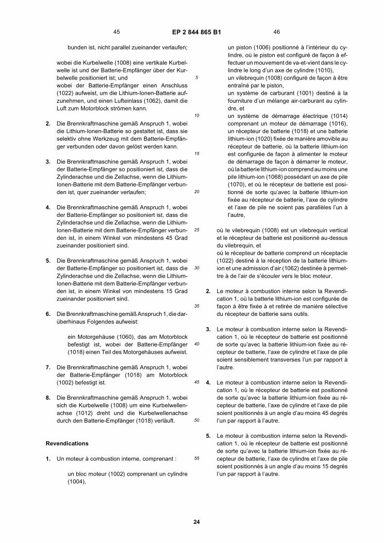
EP 2 844 865 B1
24
5
10
15
20
25
30
35
40
45
50
55
bunden ist, nicht parallel zueinander verlaufen;
wobei die Kurbelwelle (1008) eine vertikale Kurbel-welle ist und der Batterie-Empfänger über der Kur-belwelle positioniert ist; undwobei der Batterie-Empfänger einen Anschluss(1022) aufweist, um die Lithium-Ionen-Batterie auf-zunehmen, und einen Lufteinlass (1062), damit dieLuft zum Motorblock strömen kann.
2. Die Brennkraftmaschine gemäß Anspruch 1, wobeidie Lithium-Ionen-Batterie so gestaltet ist, dass sieselektiv ohne Werkzeug mit dem Batterie-Empfän-ger verbunden oder davon gelöst werden kann.
3. Die Brennkraftmaschine gemäß Anspruch 1, wobeider Batterie-Empfänger so positioniert ist, dass dieZylinderachse und die Zellachse, wenn die Lithium-Ionen-Batterie mit dem Batterie-Empfänger verbun-den ist, quer zueinander verlaufen;
4. Die Brennkraftmaschine gemäß Anspruch 1, wobeider Batterie-Empfänger so positioniert ist, dass dieZylinderachse und die Zellachse, wenn die Lithium-Ionen-Batterie mit dem Batterie-Empfänger verbun-den ist, in einem Winkel von mindestens 45 Gradzueinander positioniert sind.
5. Die Brennkraftmaschine gemäß Anspruch 1, wobeider Batterie-Empfänger so positioniert ist, dass dieZylinderachse und die Zellachse, wenn die Lithium-Ionen-Batterie mit dem Batterie-Empfänger verbun-den ist, in einem Winkel von mindestens 15 Gradzueinander positioniert sind.
6. Die Brennkraftmaschine gemäß Anspruch 1, die dar-überhinaus Folgendes aufweist:
ein Motorgehäuse (1060), das am Motorblockbefestigt ist, wobei der Batterie-Empfänger(1018) einen Teil des Motorgehäuses aufweist.
7. Die Brennkraftmaschine gemäß Anspruch 1, wobeider Batterie-Empfänger (1018) am Motorblock(1002) befestigt ist.
8. Die Brennkraftmaschine gemäß Anspruch 1, wobeisich die Kurbelwelle (1008) um eine Kurbelwellen-achse (1012) dreht und die Kurbelwellenachsedurch den Batterie-Empfänger (1018) verläuft.
Revendications
1. Un moteur à combustion interne, comprenant :
un bloc moteur (1002) comprenant un cylindre(1004),
un piston (1006) positionné à l’intérieur du cy-lindre, où le piston est configuré de façon à ef-fectuer un mouvement de va-et-vient dans le cy-lindre le long d’un axe de cylindre (1010),un vilebrequin (1008) configuré de façon à êtreentraîné par le piston,un système de carburant (1001) destiné à lafourniture d’un mélange air-carburant au cylin-dre, etun système de démarrage électrique (1014)comprenant un moteur de démarrage (1016),un récepteur de batterie (1018) et une batterielithium-ion (1020) fixée de manière amovible aurécepteur de batterie, où la batterie lithium-ionest configurée de façon à alimenter le moteurde démarrage de façon à démarrer le moteur,où la batterie lithium-ion comprend au moins unepile lithium-ion (1068) possédant un axe de pile(1070), et où le récepteur de batterie est posi-tionné de sorte qu’avec la batterie lithium-ionfixée au récepteur de batterie, l’axe de cylindreet l’axe de pile ne soient pas parallèles l’un àl’autre,
où le vilebrequin (1008) est un vilebrequin verticalet le récepteur de batterie est positionné au-dessusdu vilebrequin, etoù le récepteur de batterie comprend un réceptacle(1022) destiné à la réception de la batterie lithium-ion et une admission d’air (1062) destinée à permet-tre à de l’air de s’écouler vers le bloc moteur.
2. Le moteur à combustion interne selon la Revendi-cation 1, où la batterie lithium-ion est configurée defaçon à être fixée à et retirée de manière sélectivedu récepteur de batterie sans outils.
3. Le moteur à combustion interne selon la Revendi-cation 1, où le récepteur de batterie est positionnéde sorte qu’avec la batterie lithium-ion fixée au ré-cepteur de batterie, l’axe de cylindre et l’axe de pilesoient sensiblement transverses l’un par rapport àl’autre.
4. Le moteur à combustion interne selon la Revendi-cation 1, où le récepteur de batterie est positionnéde sorte qu’avec la batterie lithium-ion fixée au ré-cepteur de batterie, l’axe de cylindre et l’axe de pilesoient positionnés à un angle d’au moins 45 degrésl’un par rapport à l’autre.
5. Le moteur à combustion interne selon la Revendi-cation 1, où le récepteur de batterie est positionnéde sorte qu’avec la batterie lithium-ion fixée au ré-cepteur de batterie, l’axe de cylindre et l’axe de pilesoient positionnés à un angle d’au moins 15 degrésl’un par rapport à l’autre.
45 46

EP 2 844 865 B1
25
5
10
15
20
25
30
35
40
45
50
55
6. Le moteur à combustion interne selon la Revendi-cation 1, comprenant en outre :
un logement de moteur (1060) fixé au bloc mo-teur, où le récepteur de batterie (1018) com-prend une partie du logement de moteur.
7. Le moteur à combustion interne selon la Revendi-cation 1, où le récepteur de batterie (1018) est fixéau bloc moteur (1002).
8. Le moteur à combustion interne selon la Revendi-cation 1, où le vilebrequin (1008) pivote autour d’unaxe de vilebrequin (1012) et l’axe de vilebrequins’étend au travers du récepteur de batterie (1018).
47 48

EP 2 844 865 B1
26

EP 2 844 865 B1
27
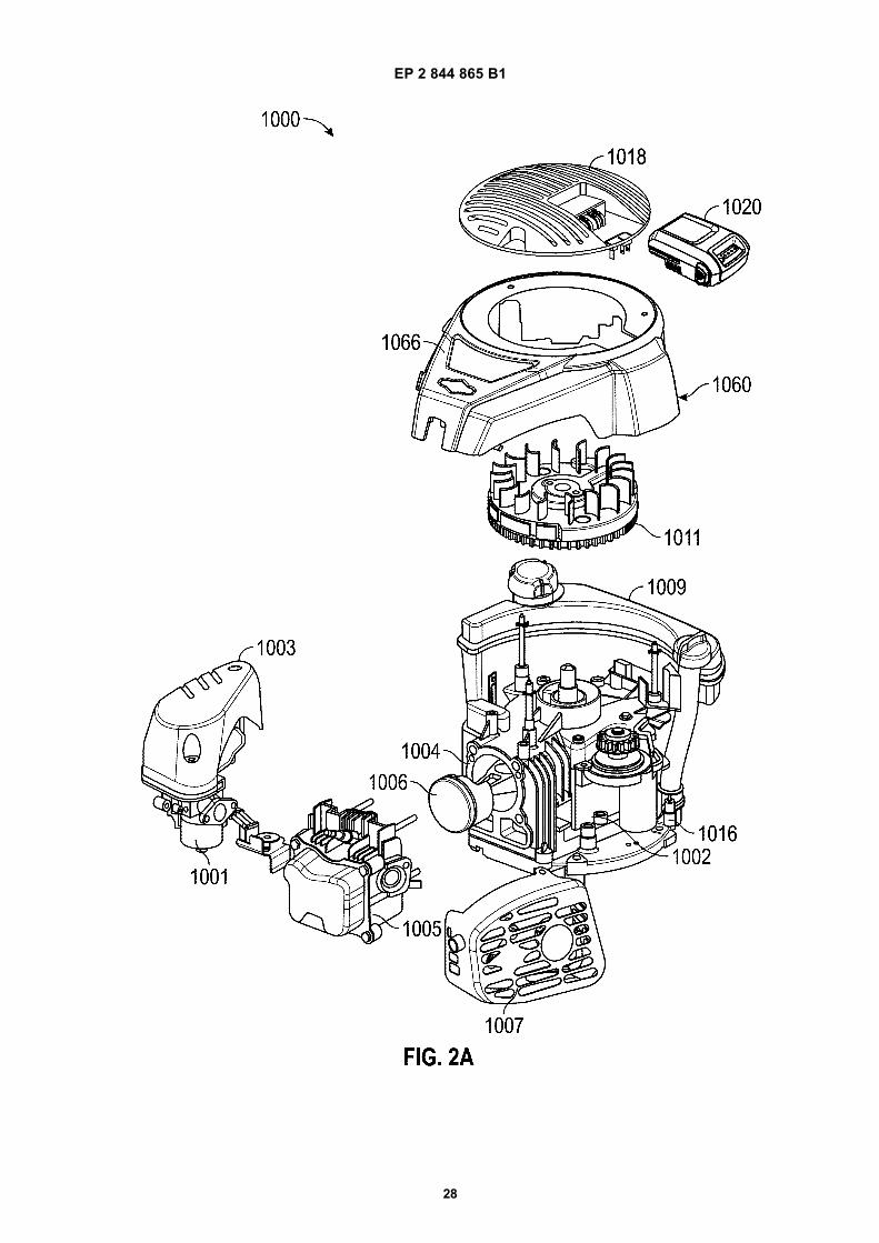
EP 2 844 865 B1
28
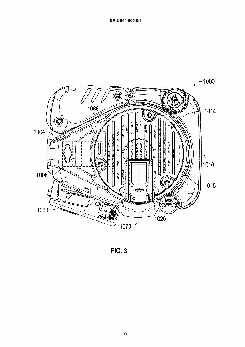
EP 2 844 865 B1
29

EP 2 844 865 B1
30

EP 2 844 865 B1
31
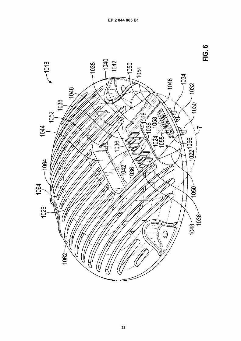
EP 2 844 865 B1
32
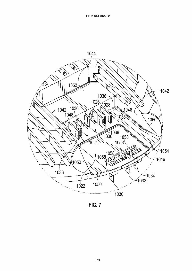
EP 2 844 865 B1
33

EP 2 844 865 B1
34

EP 2 844 865 B1
35

EP 2 844 865 B1
36

EP 2 844 865 B1
37

EP 2 844 865 B1
38

EP 2 844 865 B1
39

EP 2 844 865 B1
40

EP 2 844 865 B1
41

EP 2 844 865 B1
42

EP 2 844 865 B1
43

EP 2 844 865 B1
44

EP 2 844 865 B1
45

EP 2 844 865 B1
46

EP 2 844 865 B1
47
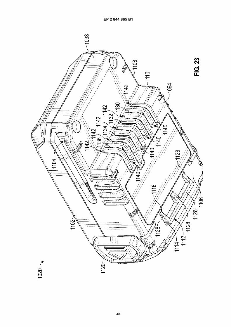
EP 2 844 865 B1
48

EP 2 844 865 B1
49

EP 2 844 865 B1
50

EP 2 844 865 B1
51

EP 2 844 865 B1
52

EP 2 844 865 B1
53

EP 2 844 865 B1
54
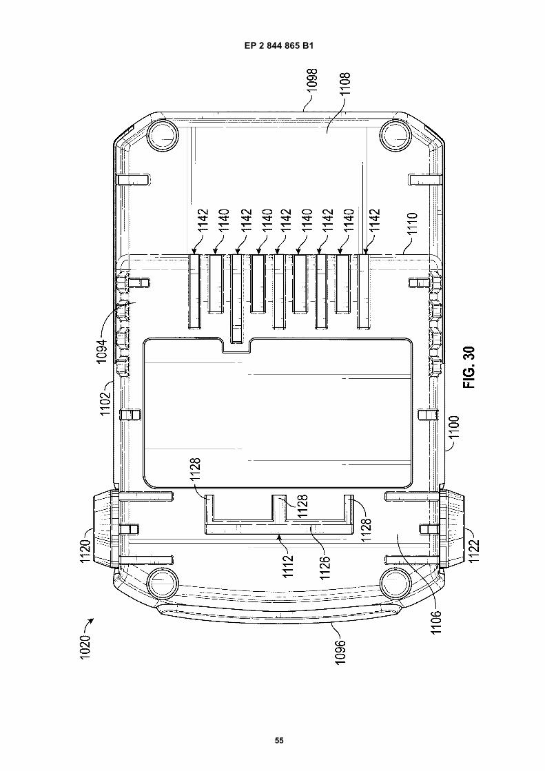
EP 2 844 865 B1
55

EP 2 844 865 B1
56
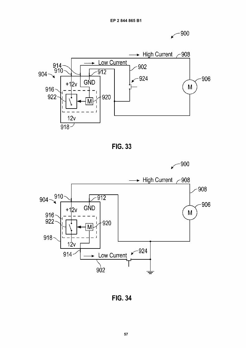
EP 2 844 865 B1
57

EP 2 844 865 B1
58

EP 2 844 865 B1
59

EP 2 844 865 B1
60

EP 2 844 865 B1
61
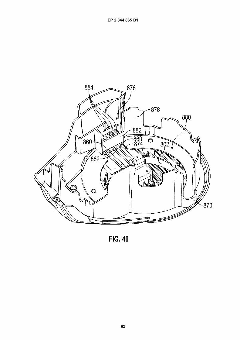
EP 2 844 865 B1
62

EP 2 844 865 B1
63

EP 2 844 865 B1
64

EP 2 844 865 B1
65

EP 2 844 865 B1
66

EP 2 844 865 B1
67

EP 2 844 865 B1
68
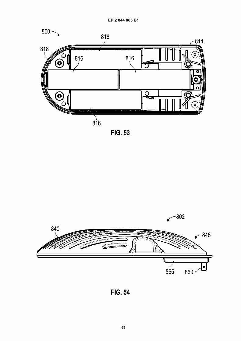
EP 2 844 865 B1
69

EP 2 844 865 B1
70

EP 2 844 865 B1
71

EP 2 844 865 B1
72

EP 2 844 865 B1
73

EP 2 844 865 B1
74

EP 2 844 865 B1
75
REFERENCES CITED IN THE DESCRIPTION
This list of references cited by the applicant is for the reader’s convenience only. It does not form part of the Europeanpatent document. Even though great care has been taken in compiling the references, errors or omissions cannot beexcluded and the EPO disclaims all liability in this regard.
Patent documents cited in the description
• US 2009284002 A [0006] • US 2013111864 A [0007]


![(19) TZZ Z¥ T - patentimages.storage.googleapis.com · [0002] Circumdental wiring techniques include metal-lic wires that are placed around one or more teeth and ... tient’s jaws](https://img.pdfslide.us/doc/110x75/5b9a2bb609d3f26e678d845f/19-tzz-z-t-0002-circumdental-wiring-techniques-include-metal-lic-wires.jpg)


![(19) TZZ ¥ T - patentimages.storage.googleapis.com · [0016] Inthe preferred embodimentsth e above- descrbed i methodsacc ordnigto th epr esentni venton i furtherc omprse:i reporting](https://img.pdfslide.us/doc/110x75/5c41ea6493f3c338dc2648aa/19-tzz-t-0016-inthe-preferred-embodimentsth-e-above-descrbed-i-methodsacc.jpg)

![(19) TZZ ¥ T - patentimages.storage.googleapis.com · 2,176,476, US Patent 4,992,474 and Tetrahedron Letters, vol. 35(50), pages 9375-9378, 1994. [0010] The present invention discloses](https://img.pdfslide.us/doc/110x75/5c25e6c309d3f2ae178c11cf/19-tzz-t-2176476-us-patent-4992474-and-tetrahedron-letters-vol.jpg)