Embed Size (px)
Citation preview
Printed by Jouve, 75001 PARIS (FR)
(19)E
P2
884
172
A1
TEPZZ 884_7 A_T(11) EP 2 884 172 A1
(12) EUROPEAN PATENT APPLICATION
(43) Date of publication: 17.06.2015 Bulletin 2015/25
(21) Application number: 13197448.7
(22) Date of filing: 16.12.2013
(51) Int Cl.:F23C 10/20 (2006.01) F23C 10/28 (2006.01)
B01J 8/18 (2006.01) F23C 10/06 (2006.01)
(84) Designated Contracting States: AL AT BE BG CH CY CZ DE DK EE ES FI FR GB GR HR HU IE IS IT LI LT LU LV MC MK MT NL NO PL PT RO RS SE SI SK SM TRDesignated Extension States: BA ME
(71) Applicant: Doosan Lentjes GmbH40880 Ratingen (DE)
(72) Inventors: • Hünchen, Heike
40477 Düsseldorf (DE)
• Piechura, Hans44801 Bochum (DE)
• Narin, Oguzhan45549 Sprockhövel (DE)
• Koch, Peter61440 Oberursel (DE)
(74) Representative: Becker, ThomasPatentanwälte Becker & Müller Turmstrasse 2240878 Ratingen (DE)
(54) Fluidized bed syphon
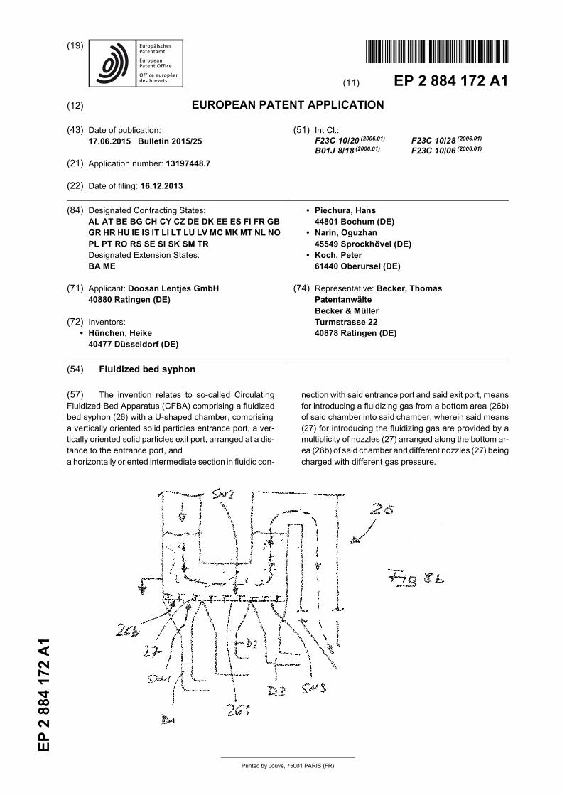
(57) The invention relates to so-called CirculatingFluidized Bed Apparatus (CFBA) comprising a fluidizedbed syphon (26) with a U-shaped chamber, comprisinga vertically oriented solid particles entrance port, a ver-tically oriented solid particles exit port, arranged at a dis-tance to the entrance port, anda horizontally oriented intermediate section in fluidic con-
nection with said entrance port and said exit port, meansfor introducing a fluidizing gas from a bottom area (26b)of said chamber into said chamber, wherein said means(27) for introducing the fluidizing gas are provided by amultiplicity of nozzles (27) arranged along the bottom ar-ea (26b) of said chamber and different nozzles (27) beingcharged with different gas pressure.
EP 2 884 172 A1
2
5
10
15
20
25
30
35
40
45
50
55
Description
[0001] The invention relates to so-called CirculatingFluidized Bed Apparatus (CFBA) and its components, inparticular
- a Circulating Fluidized Bed Reactor (CFBR) de-signed as a combustor, incineration reactor, boiler,gasifier, steam generator etc. as disclosed - i.a. - inUS 6,802,890 B2. In a typical CFBR gas (air) ispassed through a permeable grate-like bottom areaof the reactor, which grate (grid) supports a fluidizedbed of particulate material, the so-called incinerationcharge, mostly including a fuel-like material such ascoal. This gives the fuel material and other compo-nents within the fluidized bed the behaviour of a boil-ing liquid.
[0002] The aerated particulate material/fuel mixture al-lows to promote the incineration process and effectivity.[0003] The incineration charge is fluidized by theair/gas, often blown in via nozzles. The fluidized bed com-prises a so-called denseboard area, above said grateand adjacent to the said permeable reactor bottom, whilethe density of the particulate material within the fluidizedbed gets less within the upper part of the reactor space,also called the freeboard area of the fluidized bed.[0004] The reaction chamber is often limited by outerwater tube walls, made of tubes, through which waterruns, wherein said tubes are either welded directly toeach other to give a wall structure or with fins/ribs be-tween parallel running tube sections.[0005] As most of said fuel materials like coal, timberetc. contain sulphur and/or harmful substances it is nec-essary to clean the gases leaving the reaction chamber,in a suitable way.[0006] The CFBR typically has at least one outlet portat its upper end, wherein said outlet port allows the mix-ture of gas and solid particles exhausted from the reactor,to flow into at least one associated separator.
- The separator, for example a cyclone separator,serves to separate solid particles (the particulate ma-terial, including ash) from said gas. A typical designof such a separator is disclosed in US 4,615,715.Again the outer walls of the separator can be de-signed with hollow spaces to allow water flowingthrough.
- Means for the transfer of said separated solid parti-cles into at least one Fluidized Bed Heat Exchanger(FBHE) via a corresponding inlet port of said FBHE.These means may be ducts/pipes/channels or thelike.
- A syphon along the way from the separator to theCFBR and/or FBHE to allow decoupling of pressure(fields) between separator and CFBR.
- At least one Fluidized Bed Heat Exchanger (FBHE)allowing to use the heat, provided by the particulatematerial, for generating power, for example to heatup and increase the pressure of a steam transportedas a heat transfer medium via tubes or the like,through said FBHE and further to turbines or the like.
- The FBHE is equipped with at least one outlet port,also called return means, for at least part of the solidparticles on their way out of the FBHE and back intothe Circulating Fluidized Bed Reactor CFBR.
[0007] Numerous designs of such apparatus and com-ponents have been developed over the past decades.[0008] Nevertheless there is a continuous demand forimprovements, especially with respect to energy efficien-cy (typical capacity range: 50-600MW - electrical -), ef-fectiveness, simple construction, avoidance of mechan-ical and thermo-mechanical stresses, compactness (typ-ical data of a reactor chamber are: height:30-60m, width:13-40m, depth: 15-40m).[0009] The invention provides the following improve-ments with respect to a Circulating Fluidized Bed Appa-ratus, hereinafter also called CFBA, fluidized bed appa-ratus or apparatus and its components, which may berealized individually or in arbitrary combinations as farthose combinations are not explicitly excluded hereinaf-ter or excluded by technical reasons. Accordingly indi-vidual construction features may be realized individuallyand/or in arbitrary combinations. Different embodimentsmay be realized within one apparatus if proper. Accord-ingly features, disclosed in connection with one of thefollowing improvements may also be realized in connec-tion with another improvement.
Improvement A refers to a
[0010] Fluidized bed apparatus, comprising a circulat-ing fluidized bed reactor with at least one outlet port atits upper part, wherein said outlet port allows a mixtureof gas and solid particles exhausted from the circulatingfluidized bed reactor to flow into at least one associatedseparator for separating solid particles from said gas,means to transfer said separated solid particles into atleast one fluidized bed heat exchanger and return meansto transport at least part of the solid particles back intothe circulating fluidized bed reactor, wherein the circulat-ing fluidized bed reactor, the separator and the fluidizedbed heat exchanger are mounted in a suspended man-ner.[0011] The totally suspended (for example hanging)construction allows to adapt the thermal expansions ofthe associated construction elements and avoids me-chanical forces, thermo-mechanical forces and/or mo-ments between adjacent construction parts.[0012] Different thermal loads within the CFBR and anassociated FBHR typically lead to different thermal ex-pansions of both construction elements (parts of the ap-
1 2

EP 2 884 172 A1
3
5
10
15
20
25
30
35
40
45
50
55
paratus). Accordingly return means (for the solid parti-cles), for example a solid return duct, extending from theFBHR to the CFBR, typically undergoes considerablethermo-mechanical stresses, which now can be avoided.[0013] This is contrary to prior art devices with a sus-pended reactor, a heat exchanger mounted to groundand a return duct in between.[0014] Optional features are:
- The circulating fluidized bed reactor, the separatorand the fluidized bed heat exchanger are suspendedfrom a supporting structure, which may be a commonsupporting structure, for example a tripod like or agateway-like structure, a frame etc.. The suspendedmounting may be realized directly or indirectly.
- The fluidized bed heat exchanger is suspended fromthe separator. This is an example for an indirect sus-pension/hanging. The separator may be suspendedfrom a traverse/bar, while the FBHE is suspendedfrom the separator.
- The fluidized bed heat exchanger is fixedly securedto the circulating fluidized bed reactor. Again this isan indirect type of suspension. The FBHE is coupledto the CFBR, which itself may be hung to a corre-sponding frame.
- The fluidized bed heat exchanger and the fluidizedbed reactor have a common wall. This gives a com-pact design and saves one wall.
- The common wall is water-cooled.- The common wall has one or more openings fulfilling
the function of the return means or the function of anoutlet port for the solid particles respectively. A sep-arate outlet port (for example a duct) may be avoided.
- The return means are designed as a coupling withouttransferring mechanical forces or moments from saidfluidized bed reactor into said fluidized bed heat ex-changer or vice versa. This embodiment in-situ pro-vides a suspended connection between the two con-struction parts and avoids any mechanical stresses.
- The fluidized bed heat exchanger has no refractorylining. This makes is lighter and thus easier to hang.
- The fluidized bed heat exchanger has chamber wallsbeing at least partially water-cooled.
- No structural means within the FBHE, which tend tourge the solid particles to meander within the fluid-ized bed heat exchanger. Contrary to common de-signs the FBHE does not provide any separate en-trance chamber and/or return chamber throughwhich the solid particles must pass after entering theFBHE and/or before leaving it. No pre-homogeniza-tion of the solid particles being necessary any more.The solid particle stream enters the FBHE and isimmediately directed through/along the heat ex-changers.
[0015] Improvement B refers to a:
Fluidized bed apparatus, comprising a circulating flu-
idized bed reactor with at least one outlet port at itsupper part, wherein said outlet port allows a mixtureof gas and solid particles exhausted from the fluid-ized bed reactor to flow into a number (n) of associ-ated separators for separating solid particles fromsaid gas, a number (n) of means to transfer said sep-arated solid particles from said (n) separators into anumber (up to n) of discrete fluidized bed heat ex-changers, and return means to transport at least partof said solid particles back from said discrete fluid-ized bed heat exchangers into the circulating fluid-ized bed reactor, wherein the number (up to n) ofdiscrete fluidized bed heat exchangers are mechan-ically connected to provide one common fluidizedbed heat exchanger with water cooled intermediatewalls between adjacent discrete fluidized bed heatexchangers.
[0016] Typically each separator is followed by one heatexchanger (with a syphon like seal in between), while theimprovement reduces the number of construction partsinsofar as at least two, or three, or all (namely n) heatexchangers are combined into one element. This makethe apparatus more compact and more effective. Coolingmeans (water cooled walls) can be designed as commonwalls between adjacent sections of a combined heat ex-changer.[0017] Optional features are:
- The discrete fluidized bed heat exchangers are ar-ranged in a row (a line) to provide the common flu-idized bed heat exchanger, which allows a very com-pact design.
- The water cooled intermediate walls comprise water-cooled pipes, in particular metal pipes.
- The water cooled intermediate walls comprise water-cooled pipes, wherein adjacent pipes are connectedby metal fins. Fins and pipes can be welded.
- The common fluidized bed heat exchanger is sus-pended from the separator(s). This hanging con-struction reduces the installation costs and requiredspace.
- The common fluidized bed heat exchanger is fixedlysecured to the circulating fluidized bed reactor, al-lowing a compact overall design.
- The common fluidized bed heat exchanger and thecirculating fluidized bed reactor have a common wall.Again this makes the installation compact.
- The common wall is water-cooled.- The common wall has one or more openings fulfilling
the function of the return means (outlet port). Spacefor a separate return duct or the like can thus beavoided
- The fluidized bed heat exchanger has outer chamberwalls being at least partially water-cooled.
- The FBHE is designed without any structural meansurging the solid particles to meander within the flu-idized bed heat exchanger. Contrary to common de-
3 4
EP 2 884 172 A1
4
5
10
15
20
25
30
35
40
45
50
55
signs the FBHE does not provide any separate en-trance chamber and/or return chamber throughwhich the solid particles must pass after entering theFBHE and/or before leaving it. No pre-homogeniza-tion of the solid particles being necessary any more.
[0018] Improvement C refers to a:
Fluidized bed heat exchanger (FBHE) with a cham-ber, comprising at least one solid particles inlet port,at least one solid particles outlet port, arranged at adistance to the at least one inlet port, means for in-troducing a fluidizing gas from a bottom area of saidchamber into said chamber, at least one heat trans-fer means arranged within said chamber, whereinthe heat transfer means is designed in a wall-likepattern and extending substantially parallel to themain flow direction of the solid particles on their wayto and through the outlet port.
[0019] The wall like structure (a flat and compact de-sign of an individual heat transfer means) in combinationwith its orientation are the main features, allowing to ar-range a group (set) of multiple heat transfer means at adistance to each other with channels like "cavities/gaps"in between, extending as well in the flow/transport direc-tion of the solid particles towards the outlet area of thechamber.[0020] Insofar the term "wall like" does not refer to acubic design with flat surfaces but the overall volumewhich the respective heat transfer means take. A tube,meandering (zig-zag) such that the central longitunal axisof the tube lies in one imaginary plane is an example fora wall-like pattern. Tube sections may extend in differentdirections along two axis of the coordinate system.[0021] This design allows the solid particles within thefluidized bed to flow between said individual heat transfermeans, namely within said spaces (channels) formed be-tween adjacent heat transfer means, without any obsta-cles (baffles) but including the option to flow from one ofsaid channels/spaces/gaps into an adjacent one.[0022] This is true especially if the discrete heat trans-fer means are provided be bended tubes/pipes, for ex-ample according to one of the following optional features:
- The wall like pattern comprises a grid-like structure.This allows the solid particles to flow in all directionsof the coordinate system but keeps the barrier freemain transport direction towards the outlet port.
- The heat transfer means is designed as a heat ex-change tube for conveying a heat transfer mediumand arranged in a meandering fashion, thereby pro-viding a vertically oriented wall-like pattern.
- Multiple heat transfer means are arranged at a dis-tance to each other, forming a set/group of heattransfer means. This gives a package/set of heattransfer means, extending over more than 50% ofthe chamber volume.
- Heat transfer means extend about more than 60%of the chamber height.
- Heat transfer means extend about more than 70%of the chamber height.
- Heat transfer means extend from shortly above thebottom upwardly to shortly below the ceiling of saidchamber. The larger the heat transfer means are themore efficient is the total heat exchange.
- Horizontally extending sections of the meanderingheat exchange tube are at least 3 times longer thanvertically extending sections of the heat exchangetube. This underlies the main transport direction ofthe solid particles.
- Adjacent sections of the same heat exchange tubeextend at a distance to each other being 0,5 to 2 ofthe heat exchange tube diameter.
- Chamber walls being at least partially water-cooled.- No structural means urging the solid particles to me-
ander within the chamber.
[0023] They may pass the FBHE in a main directionparallel to the wall-like heat exchangers.
- No entrance chamber and/or return chamber for thesolid particles being provided in the FBHE to allowa continuous flow pattern.
- The FBHE may have a common wall with an adjacentcirculating fluidized bed reactor (CFBR) and returnmeans for the solid particles may extend at least par-tially within said common wall to make the installationmore compact.
- The common wall is a water-cooled wall.
[0024] Improvement D refers to a:
Fluidized bed heat exchanger with one chamber,comprising at least one solid particles inlet port, atleast one solid particles outlet port, arranged at adistance to the at least one inlet port, means for in-troducing a fluidizing gas from a bottom area of saidchamber into said chamber, at least two heat transfermeans within said one chamber, each being provid-ed with a heat transfer medium inlet port and a heattransfer medium outlet port, wherein a first heattransfer means is designed as a reheater and secondheat transfer means is designed as a superheaterto achieve a heat transfer medium pressure abovethat of the reheater.
[0025] This design is best realized with at least twodistinct groups/sets of heat transfer means to providedifferent thermodynamic features within the FBHE andto allow to optimize the heat transfer and efficiency of theFBHE.[0026] All heat transfer means (for example distinctsteam tubes) of one group may be linked to one centralsteam feeding line and steam outlet line respectively. In-sofar the extra work for installation is reduced to one fur-
5 6

EP 2 884 172 A1
5
5
10
15
20
25
30
35
40
45
50
55
ther feeding and extracting line, in case of two groups ofheat exchangers, while allowing to achieve different ther-modynamic conditions within the chamber.[0027] This can be complete by one or more of thefollowing features:
- The reheater is constructed to allow a heat transfermedium temperature of up to 600°C (while the inlettemperature of the heat transfer medium, for exam-ple steam, is typically about 450-550°C).
- The reheater is constructed to allow a heat transfermedium pressure of up to 50bar (typically in therange of 30-40bar).
- The superheater is constructed to allow a heat trans-fer medium temperature of up to 600°C (typically withinlet temperatures between 500 and 580°C).
- The superheater is constructed to allow a heat trans-fer medium pressure of up to 190bar (typically be-tween 160 and 180 bar).
- The fluid pressure in the superheater tubes is typi-cally more than 3, or more than 4 or even more than5 times the pressure in the reheater tubes.
- The reheater and/or the superheater each are madeof a multiplicity of heat transfer tubes, each arrangedin a meandering fashion and with a distance to eachother. Accordingly the reheater and the superheatereach have a 3-dimensional profile similar to a cube.Each tube may provide a wall-like (plate-like) struc-ture with a grate-like pattern according to the mean-dering tube sections. The solid particles passthrough channels between the heat transfer means.
- The chamber walls can be at least partially water-cooled.
- Again this FBHE and an associated circulation flu-idized bed reactor CFBR may have a common wallto reduce costs and make the apparatus compact.
- This common wall can be water-cooled.
[0028] Improvement E refers to a :
Fluidized bed apparatus, comprising a circulating flu-idized bed reactor of a vertical axial length L in itsfunctional position, with at least one outlet port at itsupper part, wherein said outlet port allows a mixtureof gas and solid particles exhausted from the fluid-ized bed reactor to flow into at least one associatedseparator for separating solid particles from said gas,means to transfer said separated solid particles intoat least one fluidized bed heat exchanger and returnmeans to transport at least part of said the solid par-ticles back into the fluidized bed reactor, wherein thereturn means are designed such that their lowermostpoint enters into the fluidized bed reactor at a mini-mum height of 0,1 L, calculated from the lowermostend of said axial length (L) of the fluidized bed reactorin its functional position.
[0029] In other words: This design gives an optimized
return position for the solid particles back into the CFBR.[0030] The minimum distance between the bottom ar-ea of the CFBR and the place, where the solid particlesenter the CFBR, guarantees that the solid particles mayfreely enter the combustion chamber (the fluidized bed)and avoids any backflow from the fluidized bed, espe-cially from the denseboard (=high pressure zone) of thefluidized bed, being the lowermost section of the fluidizedbed, right above the aerated/pressurized bottom. FBHEdoes not require any complex sealing systems along thereturn means/outlet port.[0031] The length L of the CFBR is defined as the dis-tance between the upper surface of the aerated bottom(grate-/nozzle area) and the inner surface of the chamberceiling.[0032] Optional features are:
- The return means of FBHE are designed such thattheir lowermost point enters into the fluidized bedreactor at a minimum height of 0,15L or 0,20L, cal-culated from the lowermost end of said axial length(L) of the fluidized bed reactor.
- The lowermost point of said return means of FBHEenters into the fluidized bed reactor at a distance tothe uppermost point of a dense board of said fluidizedbed reactor.
- Said return means comprise multiple flow throughopenings for said solid particles; a row of flow throughopenings, arranged at a distance to each other,equalizes the flow of the solid particles (like ash) ontheir way back into the reactor.
- The fluidized bed heat exchanger is fixedly securedto the fluidized bed reactor. A very simple construc-tion with a precise return position for the solid parti-cles.
- This is in particular true if the fluidized bed heat ex-changer and the fluidized bed reactor have a com-mon wall.
- The common wall has one or more openings fulfillingthe function of the return means. This allows againa very compact structure.
- The return means are designed as a coupling withouttransferring mechanical forces or moments from saidfluidized bed reactor into said fluidized bed heat ex-changer or vice versa.
- The fluidized bed heat exchanger has a refractorylining.
- The chamber walls of the FBHE are at least partiallywater-cooled.
- Any further return means from the separator and/ora syphon enter the CFBR shortly above its grate, i.e.directly into the denseboard (dense part) of the cir-culating fluidized bed and below the FBHE returnmeans.
[0033] Yet another improvement (F) relates to a :
Fluidized bed heat exchanger with a chamber, com-
7 8

EP 2 884 172 A1
6
5
10
15
20
25
30
35
40
45
50
55
prising at least one solid particles inlet port, at leastone solid particles outlet port, arranged at a distanceto the at least one inlet port, means for introducinga fluidizing gas from a bottom area of said chamberinto said chamber, at least one heat transfer means,arranged within said chamber, wherein at least onedistribution means being arranged in a transition re-gion between said inlet port and said chamber andupstream of said heat transfer means to allow dilu-tion of said solid particles.
[0034] This improvement relates to feeding of the par-ticulate material into the fluidized bed heat exchanger(FBHE). The FBHE (its inner chamber/space) typicallyhas a cubic or cylindrical shape of high volume.[0035] If the solid particles, coming from the separator,enter said chamber along a discrete inlet port of limitedsize, problems may arise in distributing the said particu-late material within the chamber and around/between theheat transfer means to achieve the required heat transfer.[0036] The improvement allows to distribute the solidparticles on their way into the chamber over a much largerarea, depending on the shape and size of the distributionmeans. At the same time the density of the solids withinthe particle stream is reduced, which further increasesthe heat transfer efficiency from the hot particles into theheat transfer medium (a brine, steam or the like).[0037] The term "transition region" includes the endsection of the inlet port adjacent to the chamber of theFBHE as well the adjacent section of the chamber andany area in between.[0038] Possible alternatives and embodiments includea fluidized bed heat exchanger with one or more of thefollowing features:
- The distribution means are provided by constructionelements protruding from an inner surface of saidinlet port and/or chamber. They may protrude froma wall or ceiling section.
- The distribution means are provided by at least oneof the following construction elements: bar, knob,prism, grid, grate, pyramid, spiral, saw tooth, dowel,nib, nozzle.
- The distributions means extend >30,>40 or>50% ofthe length or width of the chamber to homogenizethe stream of the fluidized bed within the chamberto its best.
- The distributions means are arranged shortly down-stream of the inlet port, i.e. along the upper part ofthe chamber.
- The inlet port enters the chamber by its ceiling. Thisgives the solid particles a transport direction follow-ing gravity.
- The inlet port enters the chamber through an upperend of a chamber wall (). Then the flow of the solidparticles is substantially horizontal before enteringthe chamber.
- Multiple heat transfer means which are arranged at
a distance to each other, allow to give the solid par-ticles a certain flow profile through the chamber(along intermediate channels).
- The chamber walls may be at least partially water-cooled.
- A fluidized bed heat exchanger without any structuralmeans (except that distribution means at the en-trance area and the heat transfer means) allows thesolid particles to pass the chamber without furthermeandering.
[0039] Improvement G refers to a design with a com-mon wall between the CFBR and FBHE, namely a[0040] Fluidized bed apparatus comprising a circulat-ing fluidized bed reactor with at least one outlet port atits upper part, wherein said outlet port allows a mixtureof gas and solid particles exhausted from the fluidizedbed reactor to flow into at least one associated separatorfor separating solid particles from said gas, means totransfer said separated solid particles into at least onefluidized bed heat exchanger as well as return means totransport at least part of said solid particles back into thecirculating fluidized bed reactor, wherein the said circu-lating fluidized bed reactor and said fluidized bed heatexchanger have at least one common wall and said returnmeans are provided within said common wall.[0041] This allows to use one wall (section) commonlyfor 2 independent components of the apparatus and thusto reduce the material and construction costs.[0042] The integration of the return means allows fur-ther reductions in construction work, material costs andincreases the efficiency. The material flow from the FBHEinto the combustion reactor becomes more reliable andmore homogeneous.[0043] Optional feature to this improvement include:
- The return means are provided by at least onethrough hole within said common wall, this is a verysimple and effective design.
- The return means are multiple through holes ar-ranged at a distance to each other (for example in ahorizontal row) within said common wall.
- The at least one through hole is inclined, with a lowerend towards the fluidized bed heat exchanger and ahigher end towards the fluidized bed reactor. Thisreduces the danger of infiltration of particles from thefluidized bed of the CFBR into the FBHE.
- The common wall provides a three-dimensional pro-file towards the fluidized bed heat exchanger. Thisallows to partly or fully integrate the sloping outletport into the common wall area.
- The common wall provides a convexity towards thefluidized bed heat exchanger. Again this allows tointegrate the inclined outlet duct/openings into theshared wall and keeps the pressure on said outflow-ing material low.
[0044] A further improvement H relates to a:
9 10
EP 2 884 172 A1
7
5
10
15
20
25
30
35
40
45
50
55
Fluidized bed heat exchanger with a chamber, com-prising at least one solid particles inlet port, at leastone solid particles outlet port, arranged at a distanceto the at least one inlet port, means for introducinga fluidizing gas from a bottom area of said chamberinto said chamber, at least one heat transfer means,arranged within said chamber, wherein said meansfor introducing the fluidizing gas are provided by amultiplicity of nozzles arranged along the bottom ar-ea of said chamber and different nozzles beingcharged with different gas pressure.
[0045] In other words:
The aerated bottom (the air/gas permeable bottomas part of the fluidized bed) is divided into sec-tions/zones/areas, where air is applied under differ-ent pressure. This allows to provide a custom-madepressure profile within the FBHE and thus to optimizethe heat transfer and particle transport. A multiplicityof air openings, mostly provided by air nozzles, canbe linked to a common air feeding duct or funnel.
[0046] Possible embodiments include:
- A multiplicity of nozzles is split into two or more noz-zle sets; each nozzle set comprising a plurality ofnozzles, wherein each nozzle sets may be chargedwith an individual gas pressure, for example with adifferent gas pressure.
- The nozzles of one nozzle set are arranged withinone common area. This allows to split the overallbottom area into two, three or more larger sections.
- The gas pressure of a nozzle set is adjustable. Thisallows to adapt the gas pressure according to localdemands.
- Each nozzle set is coupled to a corresponding gaschannel or gas distribution space respectively in or-der to adjust the required pressure in the respectivemanner with respect to all nozzles of a nozzle setconnected thereto.
- A fluidized bed heat exchanger without any structuralmeans (except distribution means at the entrancearea and the heat transfer means) allows the solidparticles to pass the chamber without further mean-dering, to the contrary: their path through the FBHEis mostly influenced by the air pressure along thebottom grate.
[0047] A similar design may be used for a syphon ar-ranged between separator and CFBR according to thefollowing improvement I:
Fluidized bed syphon with a U-shaped chamber,comprising a vertically oriented solid particles en-trance port, a vertically oriented solid particles exitport, arranged at a distance to the entrance port, anda horizontally oriented intermediate section in fluidic
connection with said entrance port and said exit port,means for introducing a fluidizing gas from a bottomarea of said chamber into said chamber, whereinsaid means for introducing the fluidizing gas are pro-vided by a multiplicity of nozzles, arranged along thebottom area of said chamber and different nozzlesbeing charged with different gas pressure.
[0048] The overall design of said syphon, serving as agas seal between components of the fluidized bed ap-paratus connected upstream and downstream of said sy-phon, is similar to that of the fluidized bed heat exchangeras disclosed above. The main difference is, that the sy-phon does not necessarily comprise any heat transfermeans.[0049] To provide a bottom area of the syphon as afluidized bed and the partition of said fluidized bed intodiscrete sections allows to adapt the air/gas volume andpressure individually for each of said sections.[0050] One possible arrangement is: A first nozzle setblows air in a counterflow to the solid particles into theentrance port, a second nozzle set provides nozzleswhich blow air/gas into the mostly horizontally orientedstream of solid particles along the intermediate sectionwhile a third nozzle set blows air into the solid particlesleaving the syphon via the exit port, wherein air/gas andsolid particles have the same transport direction alongthis exit section.[0051] Optional features for this type of syphon are:
- The multiplicity of nozzles is split into two or morenozzle sets, each nozzle set comprising a pluralityof nozzles, wherein each nozzle set is charged witha different gas pressure.
- The nozzles of one nozzle set are arranged withinone common area.
- The gas pressure of a nozzle set is adjustable.- Each nozzle set is coupled to a corresponding gas
channel or gas distribution space respectively.- Chamber walls being at least partially water-cooled.- The bottom area of the chamber extends along sub-
stantially the full width and length of the U-shapedchamber.
- A first nozzle set extends along the bottom area ofthe intermediate chamber section and discrete sec-ond and third nozzle sets along sections of said en-trance port and exit port, which follow the bottomarea of the intermediate section to both sides.
[0052] Improvement K relates to a:
Fluidized bed heat exchanger with a chamber, com-prising at least one solid particles inlet port, at leastone solid particles outlet port, arranged at a distanceto the at least one inlet port, means for introducinga fluidizing gas from a bottom area of said chamberinto said chamber, at least one heat transfer means,arranged within said chamber, at least one baffle
11 12

EP 2 884 172 A1
8
5
10
15
20
25
30
35
40
45
50
55
which extends downwardly from a chamber ceiling,substantially perpendicular to a straight line betweeninlet port and outlet port, with its lower end at a dis-tance to the heat transfer means.
[0053] This at least one baffle does not influence theflow of the solid particles within the part of the FBHEequipped with the heat transfer means as it is arrangedabove said heat transfer means and only serves to redi-rect the incoming solid particle stream (downwardly) andto equalize the pressure above the fluidized bed andalong the horizontal cross section of the chamber, in par-ticular, if provided with opening(s).[0054] The baffles have the function of separation wallsand avoid short circuits of the solid material flow (directlyfrom the inlet port to the outlet port). They urge the solidparticle stream to penetrate into the heat transfer zonebetween the heat transfer means (the channels men-tioned above). The baffle construction may interact withimprovement H.[0055] The following embodiments are optionally in-cluded:
- At least one baffle extends between opposite wallsof the chamber to improve the describe effect.
- At least one baffle has at least one opening to allowpressure adjusting/compensation within the cham-ber.
- At least one baffle is at least partially water-cooled.- At least one baffle is designed as a curtain. The cur-
tain defines a baffle with numerous small openingswhich allow pressure equalization but avoids pene-tration of the solid particles to great extent.
- Multiple baffles are arranged at a distance to eachother along said line between inlet port and outletport.
- The heat transfer means are designed as a heat ex-change tube for conveying a heat transfer mediumand arranged in a meandering fashion, thereby pro-viding a vertically oriented wall-like pattern. The in-dividual heat transfer walls extend perpendicular tothe baffles.
[0056] The invention is now described with referenceto the attached drawing, showing - all in a very schematicway - in
Figure 1A general concept of a fluidized bed apparatus ac-cording to prior artFigure 2A cross sectional view of a fluidized bed heat ex-changerFigure 3A top view on the FBHE 24 of Figure 2 along line 3-3Figure 4A cross sectional view of another embodiment of afluidized bed heat exchanger
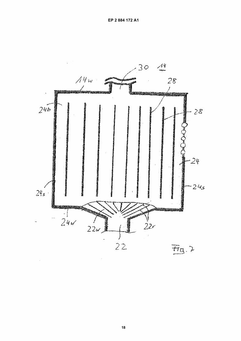
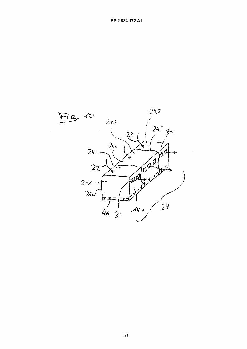
Figure 5A cross sectional view of further embodiment of afluidized bed heat exchanger A with 2 groups of heatexchangersFigure 6A top view on the FBHE of Figure 5 along line 6-6Figure 7A top view on a further example for a FBHE 24 withan amended inlet portFigure 8aA cross sectional view of an FBHE with multiple noz-zles sets in the bottom areaFigure 8bA cross sectional view of a syphon with multiple noz-zles sets in the bottom areaFigure 9An general view of a fluidized bed apparatus mount-ed in a suspended mannerFigure 10A compact fluidized bed heat exchanger in a 3-di-mensional view
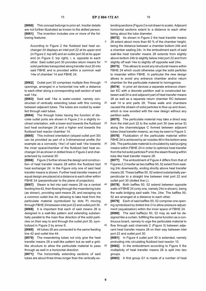
[0057] In the Figures identical an similar acting con-struction parts are identified by same numerals.[0058] Figure 1 discloses the general concept of a flu-idized bed apparatus and its main components accordingto the present invention.[0059] It comprises:
- A circulating fluidized bed reactor (CFBR) 10. Its low-er part comprises a grate-like structure 12 throughwhich air (arrow A1) is blown into a reactor chamber14 via (not shown) nozzles, thus providing a fluidizedbed (denseboard - DB -) above said grate 12, where-in said denseboard comprises a particulate materiallike coal, wood etc. to be burnt.
- The CFBR has two outlet ports 16 at opposite sidesof its upper part, allowing a mixture of gas and solidparticles exhausted from the CFBR to flow into as-sociated separators 18, namely cyclone separators.The separators serve to separate solid particles fromthe gas.
- Transfer means 20, designed as ducts, extend fromthe lower end of each separator 18 downwardly andinto an inlet port 22 along the ceiling 24c of a fluidizedbed heat exchanger (FBHE) 24.
- A syphon-like tube construction 26 (U-shaped) ex-tends from the lower end of each separator 18 intoreactor chamber 14 and enters into chamber 14shortly above grate 12 of said CFBR.
- The FBHE is equipped with (plate-like) heat transfermeans 28 and an outlet port 30 merging into reactorchamber 14 at the same vertical height as tube con-struction 26.
13 14
EP 2 884 172 A1
9
5
10
15
20
25
30
35
40
45
50
55
[0060] This concept belongs to prior art. Insofar detailsare not further illustrated as known to the skilled person.[0061] The invention includes one or more of the fol-lowing features:
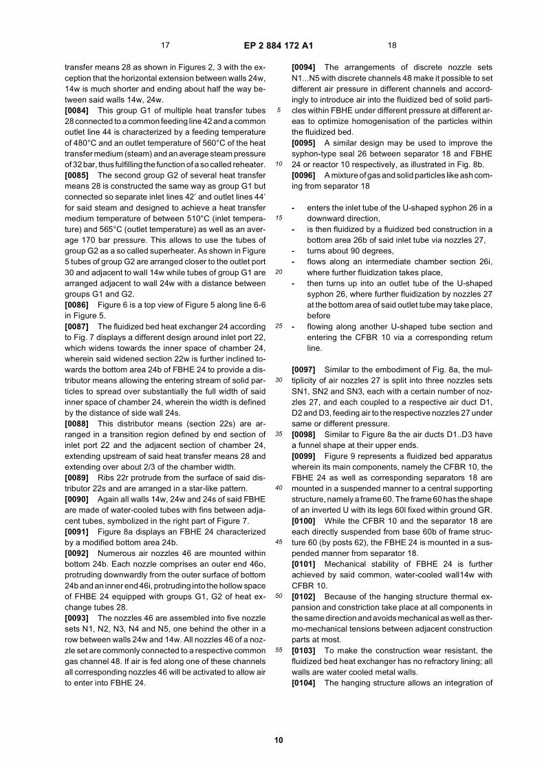
According to Figure 2 the fluidized bed heat ex-changer 24 displays an inlet port 22 at its upper end(in Figure 2: top left) and an outlet port 30 at its upperend (in Figure 2: top right), i. e. opposite to eachother. Said outlet port 30 provides return means forsolid particles transported along transfer duct 20 intosaid FBHE and is provided within a common wall14w of chamber 14 and FBHE 24.
[0062] Outlet port 30 comprises multiple flow throughopenings, arranged in a horizontal row with a distanceto each other along a corresponding wall section of saidwall 14w.[0063] Said wall 14w is water-cooled, namely con-structed of vertically extending tubes with fins runningbetween adjacent tubes. The tubes are cooled by waterfed through said tubes.[0064] The through holes having the function of dis-crete outlet ports are shown in Figure 2 in a slightly in-clined orientation, with a lower end towards the fluidizedbed heat exchanger 24 and a higher end towards thefluidized bed reactor chamber 14.[0065] This inclined orientation (sloped outlet port 30)can be provided as part of a 3-dimensional profile (forexample as a convexity 14w’) of said wall 14w towardsthe inner space/chamber of the fluidized bed heat ex-changer 24 as shown in dotted lines in Figure 2 and char-acterized by numeral 30’.[0066] Figure 2 further shows the design and construc-tion of heat transfer means 28 within the fluidized bedheat exchanger 24. In the Figure only one of said heattransfer means is shown. Further heat transfer means ofequal design are placed at a distance to each other withinFBHE 24 (perpendicular to the plane of projection).[0067] Steam is fed into said means 28 via a centralfeeding line 42, then flowing through the meandering tube(as shown), providing said means 28, and escaping viaa common outlet line 44, allowing to take heat from theparticulate material (symbolized by dots P) movingthrough FBHE 24 between inlet port 22 and outlet port 30.[0068] It is important that each of said means 28 isdesigned in a wall-like pattern and extending substan-tially parallel to the main flow direction of the solid parti-cles on their way to and through the outlet port 30, sym-bolized in Figure 2 by arrow S.[0069] All tubes 28 are connected to the same feedingline 42 and outlet line 44.[0070] The meandering tubes not only give the heattransfer means 28 a wall-like pattern but as well a grid-like structure to allow the particulate material to passthrough as well in a horizontal direction.[0071] The horizontally extending sections of saidtubes are about three times longer than the vertically ex-
tending sections (Figure 2 is not drawn to scale). Adjacenthorizontal sections extent to a distance to each otherbeing about the tube diameter.[0072] As shown in Figure 2 the heat transfer means28 extent about more than 60 % of the chamber height,being the distance between a chamber bottom 24b anda chamber sealing 24c. In the embodiment each of saidwall-like heat transfer means 28 extends from slightlyabove bottom 24b to slightly below inlet port 22 and fromslightly off wall 14w to slightly off opposite wall 24w.[0073] This allows to avoid any structural means withinFBHE 24 which could otherwise urge the solid particlesto meander within FBHE. In particular the new designallows to avoid any entrance chamber and/or returnchamber for the particulate material to homogenize.[0074] In prior art devices a separate entrance cham-ber EC with a discrete partition wall is constructed be-tween wall 24 w and adjacent part of heat transfer means28 as well as a separate return chamber RC betweenwall 14 w and parts 28. These walls and chamberscaused the stream of solid particles to flow up and down,which is now avoided with the new design without anypartition walls.[0075] The particulate material may take a direct wayfrom the inlet port 22 to the outlet port 30 (see arrow S)along the channels/gaps C formed between adjacenttubes (heat transfer means), as may be seen in Figure 3.[0076] Fluidization of the particulate material withinFBHE 24 is achieved by air nozzles 46 in the bottom area24b. The particulate material is circulated by said purgingmeans within FBHE 24 in order to optimize heat transferfrom the hot solid particles P onto the steam flowing withintube like heat transfer means 28.[0077] The embodiment of Figure 4 differs from that ofFigures 2,3 insofar as two baffles 50, 52 extent from seal-ing 24c downwardly, ending shortly above heat transfermeans 28. These baffles 50, 52 extend substantially per-pendicular to a straight line between inlet port 22 andoutlet port 30 (dotted line L).[0078] Both baffles 50, 52 extend between oppositewalls of FBHE 24 (only one, namely 24s is shown), beingthe walls bridging said walls 14w, 24w. The baffles 50,52 are arranged at a distance to each other.[0079] Each of said baffles 50, 52 comprise one open-ing symbolized by dotted line O to allow pressure adjust-ment (equalization) within the inner space of FBHE 24.[0080] The said baffle(s) 50, 52 may as well be de-signed like a curtain, fulfilling the same function as a con-tinuous board, namely to urge the particulate material toflow through said channels C (Figure 3) between adja-cent heat transfer means 28 on their way between inletport 22 and outlet port 30.[0081] In Figure 4 outlet port 30 is extended, namelyprotruding into circulating fluidized bed reactor 10.[0082] In the embodiment according to Figure 5 themultiplicity of heat transfer means 28 is split into twogroups.[0083] A first group G1 is made of a number of heat
15 16
EP 2 884 172 A1
10
5
10
15
20
25
30
35
40
45
50
55
transfer means 28 as shown in Figures 2, 3 with the ex-ception that the horizontal extension between walls 24w,14w is much shorter and ending about half the way be-tween said walls 14w, 24w.[0084] This group G1 of multiple heat transfer tubes28 connected to a common feeding line 42 and a commonoutlet line 44 is characterized by a feeding temperatureof 480°C and an outlet temperature of 560°C of the heattransfer medium (steam) and an average steam pressureof 32 bar, thus fulfilling the function of a so called reheater.[0085] The second group G2 of several heat transfermeans 28 is constructed the same way as group G1 butconnected so separate inlet lines 42’ and outlet lines 44’for said steam and designed to achieve a heat transfermedium temperature of between 510°C (inlet tempera-ture) and 565°C (outlet temperature) as well as an aver-age 170 bar pressure. This allows to use the tubes ofgroup G2 as a so called superheater. As shown in Figure5 tubes of group G2 are arranged closer to the outlet port30 and adjacent to wall 14w while tubes of group G1 arearranged adjacent to wall 24w with a distance betweengroups G1 and G2.[0086] Figure 6 is a top view of Figure 5 along line 6-6in Figure 5.[0087] The fluidized bed heat exchanger 24 accordingto Fig. 7 displays a different design around inlet port 22,which widens towards the inner space of chamber 24,wherein said widened section 22w is further inclined to-wards the bottom area 24b of FBHE 24 to provide a dis-tributor means allowing the entering stream of solid par-ticles to spread over substantially the full width of saidinner space of chamber 24, wherein the width is definedby the distance of side wall 24s.[0088] This distributor means (section 22s) are ar-ranged in a transition region defined by end section ofinlet port 22 and the adjacent section of chamber 24,extending upstream of said heat transfer means 28 andextending over about 2/3 of the chamber width.[0089] Ribs 22r protrude from the surface of said dis-tributor 22s and are arranged in a star-like pattern.[0090] Again all walls 14w, 24w and 24s of said FBHEare made of water-cooled tubes with fins between adja-cent tubes, symbolized in the right part of Figure 7.[0091] Figure 8a displays an FBHE 24 characterizedby a modified bottom area 24b.[0092] Numerous air nozzles 46 are mounted withinbottom 24b. Each nozzle comprises an outer end 46o,protruding downwardly from the outer surface of bottom24b and an inner end 46i, protruding into the hollow spaceof FHBE 24 equipped with groups G1, G2 of heat ex-change tubes 28.[0093] The nozzles 46 are assembled into five nozzlesets N1, N2, N3, N4 and N5, one behind the other in arow between walls 24w and 14w. All nozzles 46 of a noz-zle set are commonly connected to a respective commongas channel 48. If air is fed along one of these channelsall corresponding nozzles 46 will be activated to allow airto enter into FBHE 24.
[0094] The arrangements of discrete nozzle setsN1...N5 with discrete channels 48 make it possible to setdifferent air pressure in different channels and accord-ingly to introduce air into the fluidized bed of solid parti-cles within FBHE under different pressure at different ar-eas to optimize homogenisation of the particles withinthe fluidized bed.[0095] A similar design may be used to improve thesyphon-type seal 26 between separator 18 and FBHE24 or reactor 10 respectively, as illustrated in Fig. 8b.[0096] A mixture of gas and solid particles like ash com-ing from separator 18
- enters the inlet tube of the U-shaped syphon 26 in adownward direction,
- is then fluidized by a fluidized bed construction in abottom area 26b of said inlet tube via nozzles 27,
- turns about 90 degrees,- flows along an intermediate chamber section 26i,
where further fluidization takes place,- then turns up into an outlet tube of the U-shaped
syphon 26, where further fluidization by nozzles 27at the bottom area of said outlet tube may take place,before
- flowing along another U-shaped tube section andentering the CFBR 10 via a corresponding returnline.
[0097] Similar to the embodiment of Fig. 8a, the mul-tiplicity of air nozzles 27 is split into three nozzles setsSN1, SN2 and SN3, each with a certain number of noz-zles 27, and each coupled to a respective air duct D1,D2 and D3, feeding air to the respective nozzles 27 undersame or different pressure.[0098] Similar to Figure 8a the air ducts D1..D3 havea funnel shape at their upper ends.[0099] Figure 9 represents a fluidized bed apparatuswherein its main components, namely the CFBR 10, theFBHE 24 as well as corresponding separators 18 aremounted in a suspended manner to a central supportingstructure, namely a frame 60. The frame 60 has the shapeof an inverted U with its legs 60l fixed within ground GR.[0100] While the CFBR 10 and the separator 18 areeach directly suspended from base 60b of frame struc-ture 60 (by posts 62), the FBHE 24 is mounted in a sus-pended manner from separator 18.[0101] Mechanical stability of FBHE 24 is furtherachieved by said common, water-cooled wall14w withCFBR 10.[0102] Because of the hanging structure thermal ex-pansion and constriction take place at all components inthe same direction and avoids mechanical as well as ther-mo-mechanical tensions between adjacent constructionparts at most.[0103] To make the construction wear resistant, thefluidized bed heat exchanger has no refractory lining; allwalls are water cooled metal walls.[0104] The hanging structure allows an integration of
17 18

EP 2 884 172 A1
11
5
10
15
20
25
30
35
40
45
50
55
a syphon 26 with its return duct 26r without transferringmechanical forces or moments between the respectiveconstruction parts.[0105] According to Figure 9 the lowermost point LP1of outlet port 30 of fluidized bed heat exchanger 24 entersthe circulating fluidized bed reactor 10 at a height of>0,15L, calculated from the lowermost end of the axiallength L of CFBR 10. The lowermost end is defined bygrate 12 of the fluidized bed. The minimum distance of>0,1L, better >0,2L, allows to place the return means 30out of the so called denseboard DB and avoids the riskof any backflow of solid particles from the fluidized bedwithin reactor 10 into the associated construction ele-ments like FBHE 24. This feature may be combined withsloped outlet ports 30 as disclosed in Figure 2 or slopedreturn ducts 26r.[0106] The lowermost point of return duct 26r of syphon26 enters the CFBR at a height of the denseboard DB,close to grate 12 and below outlet port 30.[0107] This positioning of the two outlet ports/returnmeans 30,26r to each other is an important combinedfeature valid for various applications.[0108] In case of an apparatus comprising more thanone separator 18, for example 3 separators, Figure 10discloses an embodiment with three corresponding flu-idized bed heat exchangers 24.1, 24.2, 24.3 which aremechanically connected to provide one common fluid-ized bed heat exchanger 24 of corresponding, suitablesize, with water-cooled intermediate walls 24i. Again: allthree wall sections 14w of the common heat exchanger24 are part of the reactor wall 14, i.e. a common water-cooled wall with integrated outlet openings 30.[0109] Walls 14i, 14w are made of metal tubes, weldedto each other and connected with a fluid source to feedcooling water through said tubes.
Claims
1. Fluidized bed syphon (26) with a U-shaped chamber,comprising
1.1 a vertically oriented solid particles entranceport1.2 a vertically oriented solid particles exit port,arranged at a distance to the entrance port, and1.3 A horizontally oriented intermediate sectionin fluidic connection with said entrance port andsaid exit port,1.4 means (27) for introducing a fluidizing gasfrom a bottom area (26b) of said chamber intosaid chamber, wherein1.5 said means (27) for introducing the fluidizinggas are provided by a multiplicity of nozzles (27)arranged along the bottom area (26b) of saidchamber and different nozzles (27) beingcharged with different gas pressure.
2. Fluidized bed syphon according to claim 1, whereinthe multiplicity of nozzles (27) is split into two or morenozzle sets (SN1, SN2, SN3), each nozzle set (SN1,SN2, SN3) comprising a plurality of nozzles (27),wherein each nozzle set is charged with a differentgas pressure.
3. Fluidized bed syphon according to claim 2, whereinthe nozzles (27) of one nozzle set (SN1, SN2, SN3)are arranged within one common area.
4. Fluidized bed syphon according to claim 1, whereinthe gas pressure of a nozzle set (SN1, SN2, SN3)is adjustable.
5. Fluidized bed syphon according to claim 2, whereineach nozzle set (SN1, SN2, SN3) is coupled to acorresponding gas channel (D1, D2, D3) or gas dis-tribution space respectively.
6. Fluidized bed syphon according to claim 1 withchamber walls being at least partially water-cooled.
7. Fluidized bed syphon according to claim 1 withoutany structural means urging the solid particles to me-ander within the chamber.
8. Fluidized bed syphon according to claim 1, whereinthe bottom area (24b) of the chamber extends alongsubstantially the full width of the U-shaped chamber.
9. Fluidized bed syphon according to claim 2 with a firstnozzle set (SN2) along the bottom area (26i) of theintermediate chamber section and discrete secondand third nozzle sets (SN1, SN3) along sections ofsaid entrance port and exit port, which follow the bot-tom area (24i) of the intermediate section to bothsides.
19 20
EP 2 884 172 A1
12
EP 2 884 172 A1
13

EP 2 884 172 A1
14

EP 2 884 172 A1
15

EP 2 884 172 A1
16

EP 2 884 172 A1
17
EP 2 884 172 A1
18

EP 2 884 172 A1
19

EP 2 884 172 A1
20
EP 2 884 172 A1
21

EP 2 884 172 A1
22
5
10
15
20
25
30
35
40
45
50
55

EP 2 884 172 A1
23
5
10
15
20
25
30
35
40
45
50
55

EP 2 884 172 A1
24
REFERENCES CITED IN THE DESCRIPTION
This list of references cited by the applicant is for the reader’s convenience only. It does not form part of the Europeanpatent document. Even though great care has been taken in compiling the references, errors or omissions cannot beexcluded and the EPO disclaims all liability in this regard.
Patent documents cited in the description
• US 6802890 B2 [0001] • US 4615715 A [0006]