Embed Size (px)
Citation preview
Installation Instructions
MicroLogix™ Ethernet Interface
(Catalog Numbers 1761-NET-ENI and 1761-NET-ENIW)
Inside ...English Section ................................ 3Section française .............................. 9Deutscher Abschnitt ...................... 15Sezione italiana .............................. 21Sección en español ....................... 27Seção em Português ...................... 33
Publication 1761-IN007B-MU-P
2 MicroLogix™ Ethernet Interface
Important User Information
Solid state equipment has operational characteristics differing from those of electromechanical equipment. Safety Guidelines for the Application, Installation and Maintenance of Solid State Controls (Publication SGI-1.1 available from your local Rockwell Automation sales office or online at http://www.ab.com/manuals/gi) describes some important differences between solid state equipment and hard-wired electromechanical devices. Because of this difference, and also because of the wide variety of uses for solid state equipment, all persons responsible for applying this equipment must satisfy themselves that each intended application of this equipment is acceptable.
In no event will Rockwell Automation, Inc. be responsible or liable for indirect or consequential damages resulting from the use or application of this equipment.
The examples and diagrams in this manual are included solely for illustrative purposes. Because of the many variables and requirements associated with any particular installation, Rockwell Automation, Inc. cannot assume responsibility or liability for actual use based on the examples and diagrams.
No patent liability is assumed by Rockwell Automation, Inc. with respect to use of information, circuits, equipment, or software described in this manual.
Reproduction of the contents of this manual, in whole or in part, without written permission of Rockwell Automation, Inc. is prohibited.
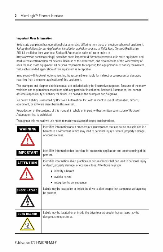
Throughout this manual we use notes to make you aware of safety considerations.
WARNINGIdentifies information about practices or circumstances that can cause an explosion in a hazardous environment, which may lead to personal injury or death, property damage, or economic loss.
IMPORTANT Identifies information that is critical for successful application and understanding of the product.
ATTENTION Identifies information about practices or circumstances that can lead to personal injury or death, property damage, or economic loss. Attentions help you:
• identify a hazard
• avoid a hazard
• recognize the consequence
SHOCK HAZARD Labels may be located on or inside the drive to alert people that dangerous voltage may be present.
BURN HAZARD Labels may be located on or inside the drive to alert people that surfaces may be dangerous temperatures.
Publication 1761-IN007B-MU-P
Installation Instructions
MicroLogix™ Ethernet InterfaceEnglish Section
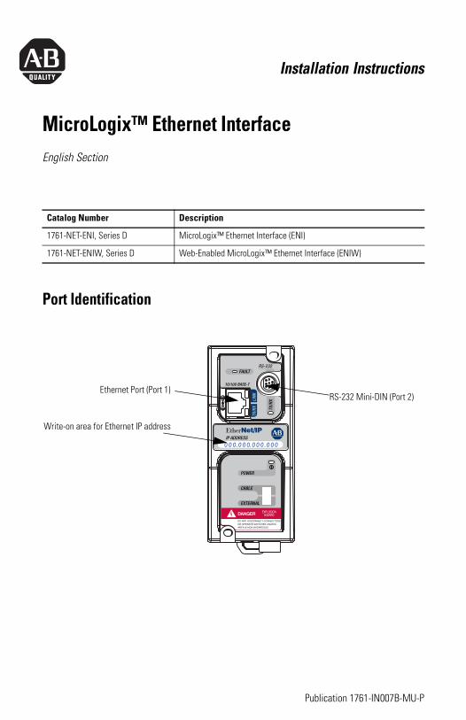
Port Identification
Catalog Number Description
1761-NET-ENI, Series D MicroLogix™ Ethernet Interface (ENI)
1761-NET-ENIW, Series D Web-Enabled MicroLogix™ Ethernet Interface (ENIW)
Write-on area for Ethernet IP address
RS-232 Mini-DIN (Port 2)Ethernet Port (Port 1)
Publication 1761-IN007B-MU-P
4 MicroLogix™ Ethernet Interface
Specifications
For More InformationFor more information on the MicroLogix Ethernet Interface, refer to publication 1761-UM006. Download a free electronic version of this publication from: www.rockwellautomation.com/literature.
Safety ConsiderationsThis equipment is suitable for use in Class I, Division 2, Groups A, B, C, D, or non-hazardous locations only. The following WARNING statement applies to use in hazardous locations.
Description Specification
24V dc Power Source Requirement 20.4 to 26.4V dc
24V dc Current Draw 50 mA typical, 100 mA maximum
Maximum Inrush Current 200 mA
Internal Isolation 710V dc for one minute
Operating Ambient Temperature 0° C to +60° C (+32° F to +140° F)
Storage Temperature -40° C to +85° C (-40° F to +175° F)
Shock operating: 30g, ±3 times each axisnon-operating: 35g (DIN rail mount) 50g (panel mount), ±3 times each axis
Vibration operating: 10 to 500 Hz, 5.0g, 0.030 in. peak-to-peak, 2 hours each axis
Agency Certification(1)
(1) Shielded Ethernet cable required for marine certification.
UL 1604C-UL C22.2 No. 213Class I Division 2 Groups A,B,C,D CE compliant for all applicable directivesC-Tick marked for all applicable acts
Publication 1761-IN007B-MU-P
MicroLogix™ Ethernet Interface 5
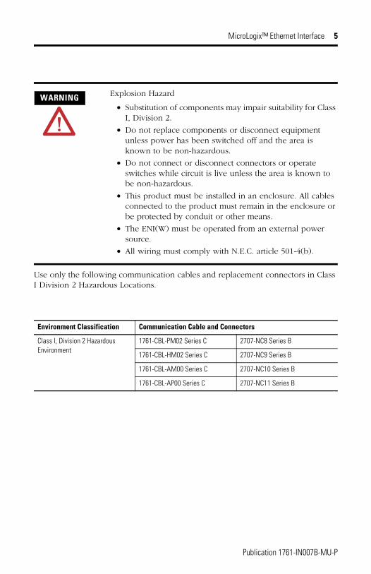
Use only the following communication cables and replacement connectors in Class I Division 2 Hazardous Locations.
WARNING Explosion Hazard
• Substitution of components may impair suitability for Class I, Division 2.
• Do not replace components or disconnect equipment unless power has been switched off and the area is known to be non-hazardous.
• Do not connect or disconnect connectors or operate switches while circuit is live unless the area is known to be non-hazardous.
• This product must be installed in an enclosure. All cables connected to the product must remain in the enclosure or be protected by conduit or other means.
• The ENI(W) must be operated from an external power source.
• All wiring must comply with N.E.C. article 501-4(b).
Environment Classification Communication Cable and Connectors
Class I, Division 2 Hazardous Environment
1761-CBL-PM02 Series C 2707-NC8 Series B
1761-CBL-HM02 Series C 2707-NC9 Series B
1761-CBL-AM00 Series C 2707-NC10 Series B
1761-CBL-AP00 Series C 2707-NC11 Series B
Publication 1761-IN007B-MU-P
6 MicroLogix™ Ethernet Interface
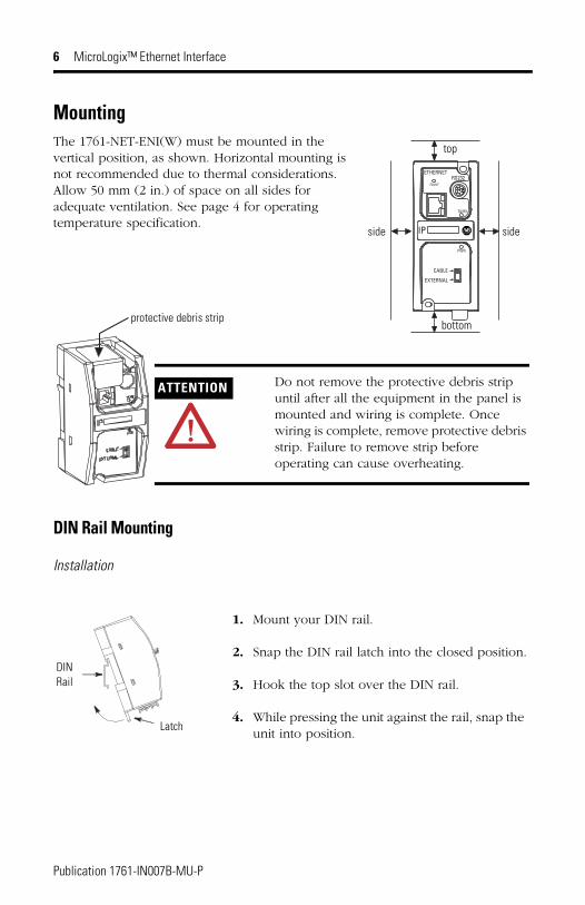
MountingThe 1761-NET-ENI(W) must be mounted in the vertical position, as shown. Horizontal mounting is not recommended due to thermal considerations. Allow 50 mm (2 in.) of space on all sides for adequate ventilation. See page 4 for operating temperature specification.
DIN Rail Mounting
Installation
ETHERNET
FAULT
RS232
TX/RX
PWR
CABLE
EXTERNAL
IP
top
bottom
side side
protective debris strip
ATTENTION Do not remove the protective debris strip until after all the equipment in the panel is mounted and wiring is complete. Once wiring is complete, remove protective debris strip. Failure to remove strip before operating can cause overheating.
DINRail
Latch
1. Mount your DIN rail.
2. Snap the DIN rail latch into the closed position.
3. Hook the top slot over the DIN rail.
4. While pressing the unit against the rail, snap the unit into position.
Publication 1761-IN007B-MU-P
MicroLogix™ Ethernet Interface 7
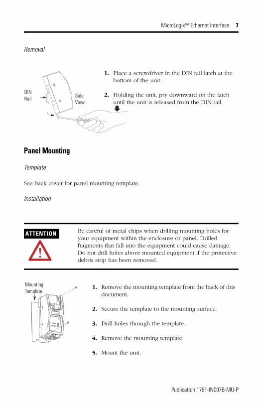
Removal
Panel Mounting
Template
See back cover for panel mounting template.
Installation
ATTENTION Be careful of metal chips when drilling mounting holes for your equipment within the enclosure or panel. Drilled fragments that fall into the equipment could cause damage. Do not drill holes above mounted equipment if the protective debris strip has been removed.
1. Place a screwdriver in the DIN rail latch at the bottom of the unit.
2. Holding the unit, pry downward on the latch until the unit is released from the DIN rail.
DINRail Side
View
1. Remove the mounting template from the back of this document.
2. Secure the template to the mounting surface.
3. Drill holes through the template.
4. Remove the mounting template.
5. Mount the unit.
MountingTemplate
Publication 1761-IN007B-MU-P
8 MicroLogix™ Ethernet Interface
External Power Supply Wiring
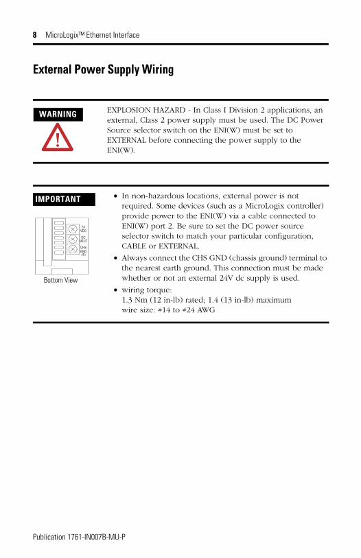
WARNING EXPLOSION HAZARD - In Class I Division 2 applications, an external, Class 2 power supply must be used. The DC Power Source selector switch on the ENI(W) must be set to EXTERNAL before connecting the power supply to the ENI(W).
IMPORTANT • In non-hazardous locations, external power is not required. Some devices (such as a MicroLogix controller) provide power to the ENI(W) via a cable connected to ENI(W) port 2. Be sure to set the DC power source selector switch to match your particular configuration, CABLE or EXTERNAL.
• Always connect the CHS GND (chassis ground) terminal to the nearest earth ground. This connection must be made whether or not an external 24V dc supply is used.
• wiring torque: 1.3 Nm (12 in-lb) rated; 1.4 (13 in-lb) maximumwire size: #14 to #24 AWG
VDC24
DCNEUT
CHSGND
Bottom View
Publication 1761-IN007B-MU-P
Notice d’installation
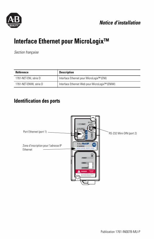
Interface Ethernet pour MicroLogix™Section française
Identification des ports
Référence Description
1761-NET-ENI, série D Interface Ethernet pour MicroLogix™ (ENI)
1761-NET-ENIW, série D Interface Ethernet Web pour MicroLogix™ (ENIW)
Zone d’inscription pour l’adresse IP Ethernet
RS-232 Mini-DIN (port 2)Port Ethernet (port 1)
Publication 1761-IN007B-MU-P
10 Interface Ethernet pour MicroLogix™
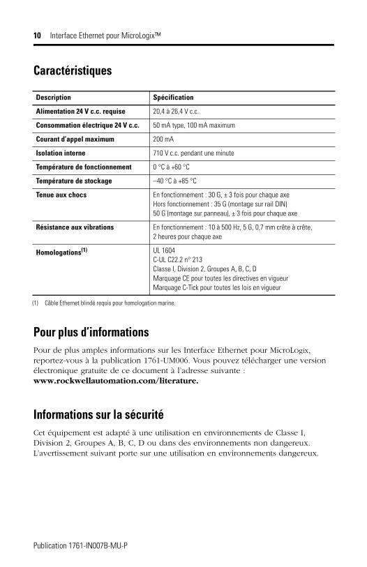
Caractéristiques
Pour plus d’informationsPour de plus amples informations sur les Interface Ethernet pour MicroLogix, reportez-vous à la publication 1761-UM006. Vous pouvez télécharger une version électronique gratuite de ce document à l’adresse suivante : www.rockwellautomation.com/literature.
Informations sur la sécuritéCet équipement est adapté à une utilisation en environnements de Classe I, Division 2, Groupes A, B, C, D ou dans des environnements non dangereux. L’avertissement suivant porte sur une utilisation en environnements dangereux.
Description Spécification
Alimentation 24 V c.c. requise 20,4 à 26,4 V c.c.
Consommation électrique 24 V c.c. 50 mA type, 100 mA maximum
Courant d’appel maximum 200 mA
Isolation interne 710 V c.c. pendant une minute
Température de fonctionnement 0 °C à +60 °C
Température de stockage –40 °C à +85 °C
Tenue aux chocs En fonctionnement : 30 G, ± 3 fois pour chaque axeHors fonctionnement : 35 G (montage sur rail DIN) 50 G (montage sur panneau), ± 3 fois pour chaque axe
Résistance aux vibrations En fonctionnement : 10 à 500 Hz, 5 G, 0,7 mm crête à crête, 2 heures pour chaque axe
Homologations(1)
(1) Câble Ethernet blindé requis pour homologation marine.
UL 1604C-UL C22.2 n° 213 Classe I, Division 2, Groupes A, B, C, D Marquage CE pour toutes les directives en vigueurMarquage C-Tick pour toutes les lois en vigueur
Publication 1761-IN007B-MU-P
Interface Ethernet pour MicroLogix™ 11
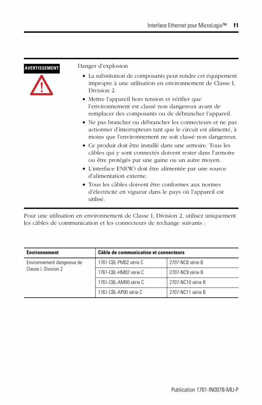
Pour une utilisation en environnement de Classe I, Division 2, utilisez uniquement les câbles de communication et les connecteurs de rechange suivants :
AVERTISSEMENT Danger d’explosion
• La substitution de composants peut rendre cet équipement impropre à une utilisation en environnement de Classe I, Division 2.
• Mettre l’appareil hors tension et vérifier que l’environnement est classé non dangereux avant de remplacer des composants ou de débrancher l’appareil.
• Ne pas brancher ou débrancher les connecteurs et ne pas actionner d’interrupteurs tant que le circuit est alimenté, à moins que l’environnement ne soit classé non dangereux.
• Ce produit doit être installé dans une armoire. Tous les câbles qui y sont connectés doivent rester dans l’armoire ou être protégés par une gaine ou un autre moyen.
• L’interface ENI(W) doit être alimentée par une source d’alimentation externe.
• Tous les câbles doivent être conformes aux normes d’électricité en vigueur dans le pays où l’appareil est utilisé.
Environnement Câble de communication et connecteurs
Environnement dangereux de Classe I, Division 2
1761-CBL-PM02 série C 2707-NC8 série B
1761-CBL-HM02 série C 2707-NC9 série B
1761-CBL-AM00 série C 2707-NC10 série B
1761-CBL-AP00 série C 2707-NC11 série B
Publication 1761-IN007B-MU-P
12 Interface Ethernet pour MicroLogix™
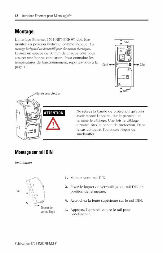
MontageL’interface Ethernet 1761-NET-ENI(W) doit être montée en position verticale, comme indiqué. Un montage horizontal est déconseillé pour des raisons thermiques. Laissez un espace de 50 mm de chaque côté pour assurer une bonne ventilation. Pour connaître les températures de fonctionnement, reportez-vous à la page 10.
Montage sur rail DIN
Installation
ETHERNET
FAULT
RS232
TX/RX
PWR
CABLE
EXTERNAL
IP
Haut
Bas
Côté Côté
Bande de protection
ATTENTION Ne retirez la bande de protection qu’après avoir monté l’appareil sur le panneau et terminé le câblage. Une fois le câblage terminé, ôtez la bande de protection. Dans le cas contraire, l’automate risque de surchauffer.
Rail
Loquet de verrouillage
1. Montez votre rail DIN.
2. Fixez le loquet de verrouillage du rail DIN en position de fermeture.
3. Accrochez la fente supérieure sur le rail DIN.
4. Appuyez l’appareil contre le rail pour l’enclencher.
Publication 1761-IN007B-MU-P
Interface Ethernet pour MicroLogix™ 13
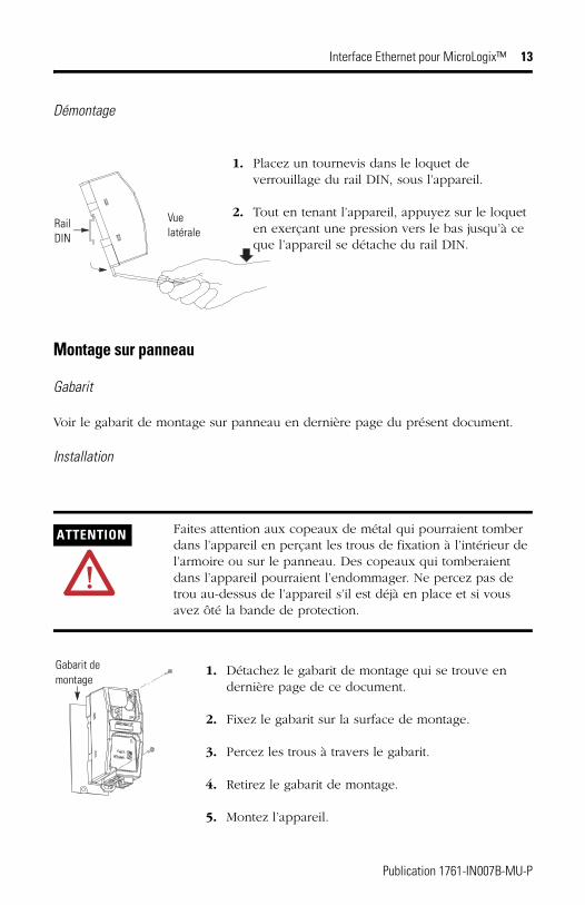
Démontage
Montage sur panneau
Gabarit
Voir le gabarit de montage sur panneau en dernière page du présent document.
Installation
ATTENTION Faites attention aux copeaux de métal qui pourraient tomber dans l’appareil en perçant les trous de fixation à l’intérieur de l’armoire ou sur le panneau. Des copeaux qui tomberaient dans l’appareil pourraient l’endommager. Ne percez pas de trou au-dessus de l’appareil s’il est déjà en place et si vous avez ôté la bande de protection.
1. Placez un tournevis dans le loquet de verrouillage du rail DIN, sous l’appareil.
2. Tout en tenant l’appareil, appuyez sur le loquet en exerçant une pression vers le bas jusqu’à ce que l’appareil se détache du rail DIN.
Rail DIN
Vue latérale
1. Détachez le gabarit de montage qui se trouve en dernière page de ce document.
2. Fixez le gabarit sur la surface de montage.
3. Percez les trous à travers le gabarit.
4. Retirez le gabarit de montage.
5. Montez l’appareil.
Gabarit de montage
Publication 1761-IN007B-MU-P
14 Interface Ethernet pour MicroLogix™
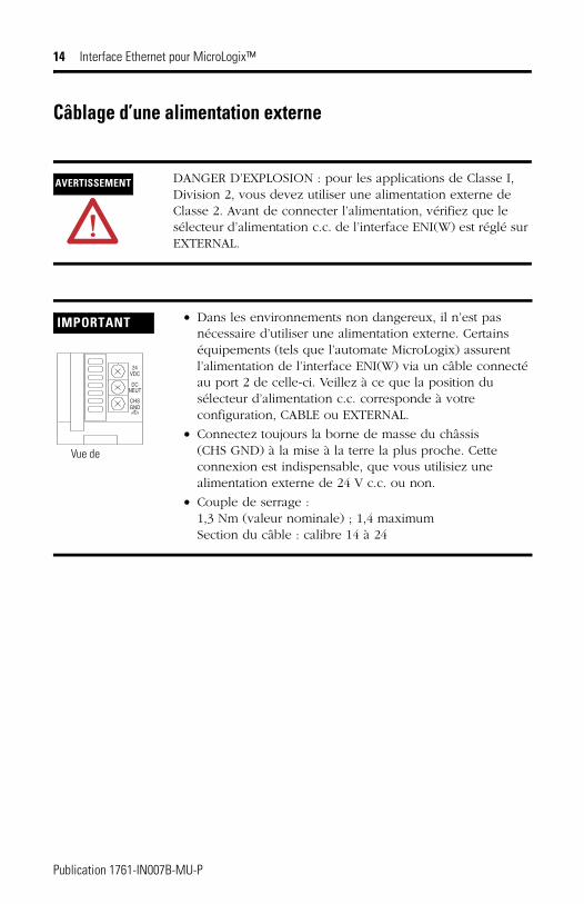
Câblage d’une alimentation externe
AVERTISSEMENT DANGER D’EXPLOSION : pour les applications de Classe I, Division 2, vous devez utiliser une alimentation externe de Classe 2. Avant de connecter l’alimentation, vérifiez que le sélecteur d’alimentation c.c. de l’interface ENI(W) est réglé sur EXTERNAL.
IMPORTANT • Dans les environnements non dangereux, il n’est pas nécessaire d’utiliser une alimentation externe. Certains équipements (tels que l’automate MicroLogix) assurent l’alimentation de l’interface ENI(W) via un câble connecté au port 2 de celle-ci. Veillez à ce que la position du sélecteur d’alimentation c.c. corresponde à votre configuration, CABLE ou EXTERNAL.
• Connectez toujours la borne de masse du châssis (CHS GND) à la mise à la terre la plus proche. Cette connexion est indispensable, que vous utilisiez une alimentation externe de 24 V c.c. ou non.
• Couple de serrage : 1,3 Nm (valeur nominale) ; 1,4 maximumSection du câble : calibre 14 à 24
VDC24
DCNEUT
CHSGND
Vue de
Publication 1761-IN007B-MU-P
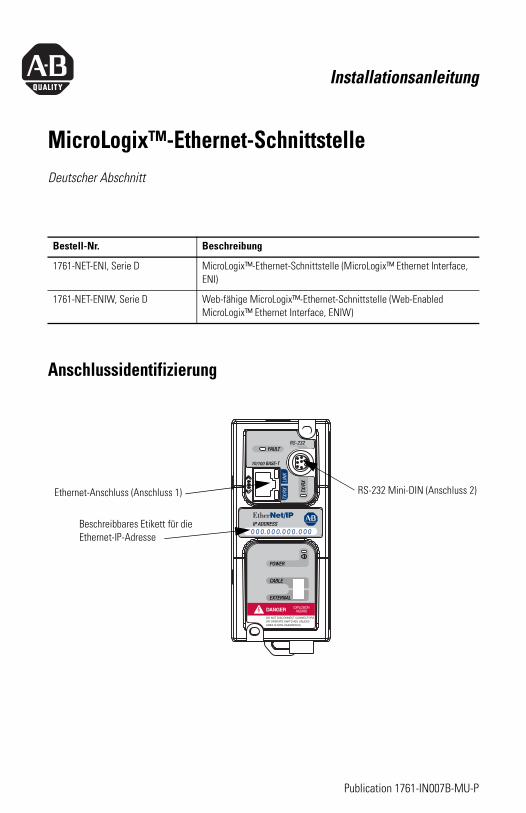
Installationsanleitung
MicroLogix™-Ethernet-SchnittstelleDeutscher Abschnitt
Anschlussidentifizierung
Bestell-Nr. Beschreibung
1761-NET-ENI, Serie D MicroLogix™-Ethernet-Schnittstelle (MicroLogix™ Ethernet Interface, ENI)
1761-NET-ENIW, Serie D Web-fähige MicroLogix™-Ethernet-Schnittstelle (Web-Enabled MicroLogix™ Ethernet Interface, ENIW)
Ethernet-Anschluss (Anschluss 1)
Beschreibbares Etikett für die Ethernet-IP-Adresse
RS-232 Mini-DIN (Anschluss 2)
Publication 1761-IN007B-MU-P
16 MicroLogix™-Ethernet-Schnittstelle
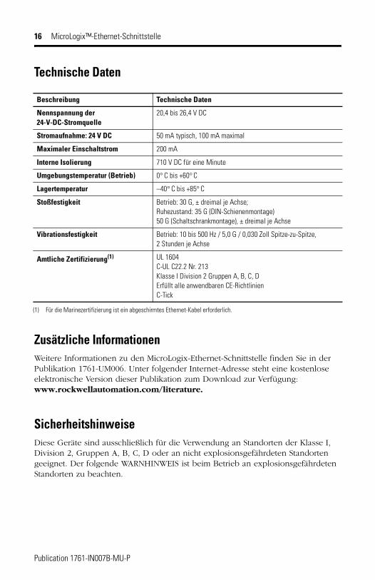
Technische Daten
Zusätzliche InformationenWeitere Informationen zu den MicroLogix-Ethernet-Schnittstelle finden Sie in der Publikation 1761-UM006. Unter folgender Internet-Adresse steht eine kostenlose elektronische Version dieser Publikation zum Download zur Verfügung: www.rockwellautomation.com/literature.
SicherheitshinweiseDiese Geräte sind ausschließlich für die Verwendung an Standorten der Klasse I, Division 2, Gruppen A, B, C, D oder an nicht explosionsgefährdeten Standorten geeignet. Der folgende WARNHINWEIS ist beim Betrieb an explosionsgefährdeten Standorten zu beachten.
Beschreibung Technische Daten
Nennspannung der 24-V-DC-Stromquelle
20,4 bis 26,4 V DC
Stromaufnahme: 24 V DC 50 mA typisch, 100 mA maximal
Maximaler Einschaltstrom 200 mA
Interne Isolierung 710 V DC für eine Minute
Umgebungstemperatur (Betrieb) 0° C bis +60° C
Lagertemperatur –40° C bis +85° C
Stoßfestigkeit Betrieb: 30 G, ± dreimal je Achse; Ruhezustand: 35 G (DIN-Schienenmontage) 50 G (Schaltschrankmontage), ± dreimal je Achse
Vibrationsfestigkeit Betrieb: 10 bis 500 Hz / 5,0 G / 0,030 Zoll Spitze-zu-Spitze, 2 Stunden je Achse
Amtliche Zertifizierung(1)
(1) Für die Marinezertifizierung ist ein abgeschirmtes Ethernet-Kabel erforderlich.
UL 1604C-UL C22.2 Nr. 213 Klasse I Division 2 Gruppen A, B, C, D Erfüllt alle anwendbaren CE-RichtlinienC-Tick
Publication 1761-IN007B-MU-P
MicroLogix™-Ethernet-Schnittstelle 17
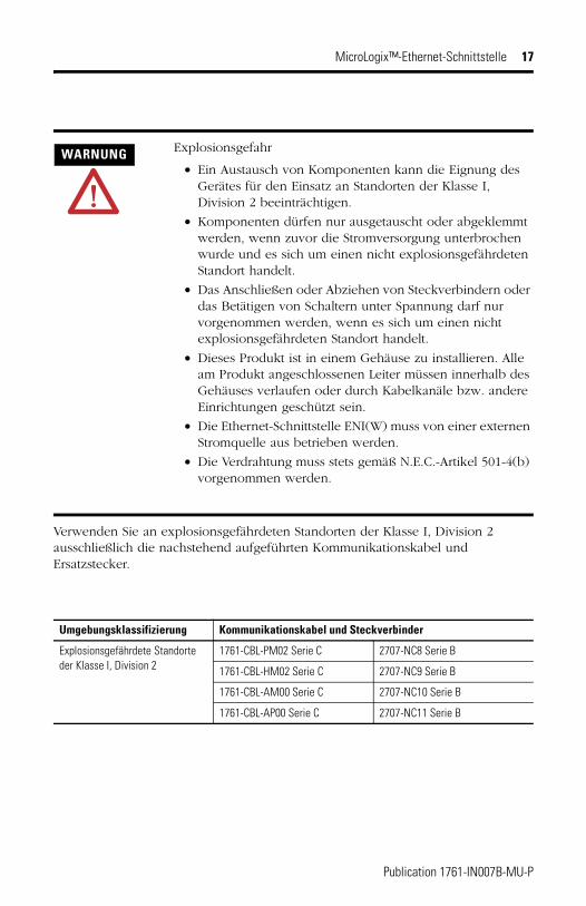
Verwenden Sie an explosionsgefährdeten Standorten der Klasse I, Division 2 ausschließlich die nachstehend aufgeführten Kommunikationskabel und Ersatzstecker.
WARNUNG Explosionsgefahr
• Ein Austausch von Komponenten kann die Eignung des Gerätes für den Einsatz an Standorten der Klasse I, Division 2 beeinträchtigen.
• Komponenten dürfen nur ausgetauscht oder abgeklemmt werden, wenn zuvor die Stromversorgung unterbrochen wurde und es sich um einen nicht explosionsgefährdeten Standort handelt.
• Das Anschließen oder Abziehen von Steckverbindern oder das Betätigen von Schaltern unter Spannung darf nur vorgenommen werden, wenn es sich um einen nicht explosionsgefährdeten Standort handelt.
• Dieses Produkt ist in einem Gehäuse zu installieren. Alle am Produkt angeschlossenen Leiter müssen innerhalb des Gehäuses verlaufen oder durch Kabelkanäle bzw. andere Einrichtungen geschützt sein.
• Die Ethernet-Schnittstelle ENI(W) muss von einer externen Stromquelle aus betrieben werden.
• Die Verdrahtung muss stets gemäß N.E.C.-Artikel 501-4(b) vorgenommen werden.
Umgebungsklassifizierung Kommunikationskabel und Steckverbinder
Explosionsgefährdete Standorte der Klasse I, Division 2
1761-CBL-PM02 Serie C 2707-NC8 Serie B
1761-CBL-HM02 Serie C 2707-NC9 Serie B
1761-CBL-AM00 Serie C 2707-NC10 Serie B
1761-CBL-AP00 Serie C 2707-NC11 Serie B
Publication 1761-IN007B-MU-P
18 MicroLogix™-Ethernet-Schnittstelle
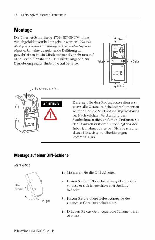
MontageDie Ethernet-Schnittstelle 1761-NET-ENI(W) muss wie abgebildet vertikal eingebaut werden. Von einer Montage in horizontaler Einbaulage wird aus Temperaturgründen abgeraten. Um eine ausreichende Belüftung zu gewährleisten ist ein Mindestabstand von 50 mm auf allen Seiten einzuhalten. Detaillierte Angaben zur Betriebstemperatur finden Sie auf Seite 16.
Montage auf einer DIN-Schiene
Installation
ETHERNET
FAULT
RS232
TX/RX
PWR
CABLE
EXTERNAL
IP
Oben
Unten
Seite Seite
Staubschutzstreifen
ACHTUNG Entfernen Sie den Staubschutzstreifen erst, wenn alle Geräte im Schaltschrank montiert wurden und die Verdrahtung abgeschlossen ist. Nach erfolgter Verdrahtung den Staubschutzstreifen entfernen. Entfernen Sie den Staubschutzstreifen unbedingt vor der Inbetriebnahme, da es bei Nichtbeachtung dieses Hinweises zu Überhitzungen kommen kann.
DIN-Schien
Riegel
1. Montieren Sie die DIN-Schiene.
2. Lassen Sie den DIN-Schienen-Regel einrasten, so dass er sich in geschlossener Stellung befindet.
3. Haken Sie die obere Befestigungsrille des Gerätes auf der DIN-Schiene ein.
4. Drücken Sie das Gerät gegen die Schiene, bis es einrastet.
Publication 1761-IN007B-MU-P
MicroLogix™-Ethernet-Schnittstelle 19
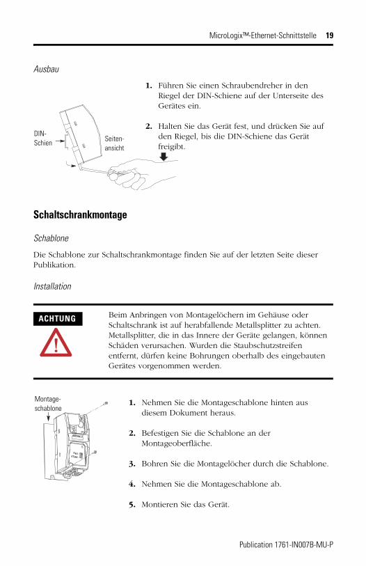
Ausbau
Schaltschrankmontage
Schablone
Die Schablone zur Schaltschrankmontage finden Sie auf der letzten Seite dieser Publikation.
Installation
ACHTUNG Beim Anbringen von Montagelöchern im Gehäuse oder Schaltschrank ist auf herabfallende Metallsplitter zu achten. Metallsplitter, die in das Innere der Geräte gelangen, können Schäden verursachen. Wurden die Staubschutzstreifen entfernt, dürfen keine Bohrungen oberhalb des eingebauten Gerätes vorgenommen werden.
1. Führen Sie einen Schraubendreher in den Riegel der DIN-Schiene auf der Unterseite des Gerätes ein.
2. Halten Sie das Gerät fest, und drücken Sie auf den Riegel, bis die DIN-Schiene das Gerät freigibt.
DIN-Schien Seiten-
ansicht
1. Nehmen Sie die Montageschablone hinten aus diesem Dokument heraus.
2. Befestigen Sie die Schablone an der Montageoberfläche.
3. Bohren Sie die Montagelöcher durch die Schablone.
4. Nehmen Sie die Montageschablone ab.
5. Montieren Sie das Gerät.
Montage-schablone
Publication 1761-IN007B-MU-P
20 MicroLogix™-Ethernet-Schnittstelle
Verdrahtung des externen Netzteils
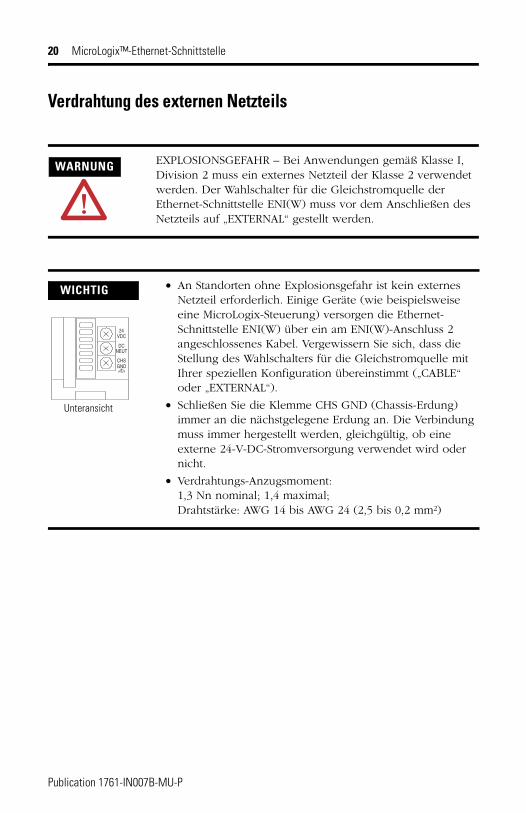
WARNUNG EXPLOSIONSGEFAHR – Bei Anwendungen gemäß Klasse I, Division 2 muss ein externes Netzteil der Klasse 2 verwendet werden. Der Wahlschalter für die Gleichstromquelle der Ethernet-Schnittstelle ENI(W) muss vor dem Anschließen des Netzteils auf „EXTERNAL“ gestellt werden.
WICHTIG • An Standorten ohne Explosionsgefahr ist kein externes Netzteil erforderlich. Einige Geräte (wie beispielsweise eine MicroLogix-Steuerung) versorgen die Ethernet-Schnittstelle ENI(W) über ein am ENI(W)-Anschluss 2 angeschlossenes Kabel. Vergewissern Sie sich, dass die Stellung des Wahlschalters für die Gleichstromquelle mit Ihrer speziellen Konfiguration übereinstimmt („CABLE“ oder „EXTERNAL“).
• Schließen Sie die Klemme CHS GND (Chassis-Erdung) immer an die nächstgelegene Erdung an. Die Verbindung muss immer hergestellt werden, gleichgültig, ob eine externe 24-V-DC-Stromversorgung verwendet wird oder nicht.
• Verdrahtungs-Anzugsmoment: 1,3 Nn nominal; 1,4 maximal;Drahtstärke: AWG 14 bis AWG 24 (2,5 bis 0,2 mm²)
VDC24
DCNEUT
CHSGND
Unteransicht
Publication 1761-IN007B-MU-P
Istruzioni relative all’installazione
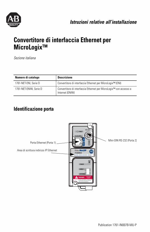
Convertitore di interfaccia Ethernet per MicroLogix™Sezione italiana
Identificazione porta
Numero di catalogo Descrizione
1761-NET-ENI, Serie D Convertitore di interfaccia Ethernet per MicroLogix™ (ENI)
1761-NET-ENIW, Serie D Convertitore di interfaccia Ethernet per MicroLogix™ con accesso a Internet (ENIW)
Area di scrittura indirizzo IP Ethernet
Mini-DIN RS-232 (Porta 2)Porta Ethernet (Porta 1)
Publication 1761-IN007B-MU-P
22 Convertitore di interfaccia Ethernet per MicroLogix™
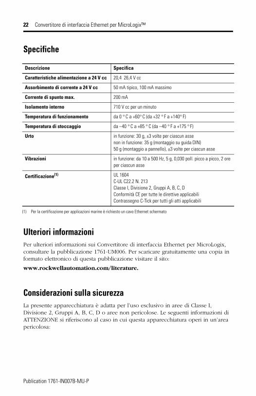
Specifiche
Ulteriori informazioniPer ulteriori informazioni sui Convertitore di interfaccia Ethernet per MicroLogix, consultare la pubblicazione 1761-UM006. Per scaricare gratuitamente una copia in formato elettronico di questa pubblicazione visitare il sito:
www.rockwellautomation.com/literature.
Considerazioni sulla sicurezzaLa presente apparecchiatura è adatta per l’uso esclusivo in aree di Classe I, Divisione 2, Gruppi A, B, C, D o aree non pericolose. Le seguenti informazioni di ATTENZIONE si riferiscono al caso in cui questa apparecchiatura operi in un’area pericolosa:
Descrizione Specifica
Caratteristiche alimentazione a 24 V cc 20,4 26,4 V cc
Assorbimento di corrente a 24 V cc 50 mA tipico, 100 mA massimo
Corrente di spunto max. 200 mA
Isolamento interno 710 V cc per un minuto
Temperatura di funzionamento da 0 ° C a +60° C (da +32 ° F a +140° F)
Temperatura di stoccaggio da –40 ° C a +85 ° C (da –40 ° F a +175 ° F)
Urto in funzione: 30 g, ±3 volte per ciascun assenon in funzione: 35 g (montaggio su guida DIN) 50 g (montaggio a pannello), ±3 volte per ciascun asse
Vibrazioni in funzione: da 10 a 500 Hz, 5 g, 0,030 poll. picco a picco, 2 ore per ciascun asse
Certificazione(1)
(1) Per la certificazione per applicazioni marine è richiesto un cavo Ethernet schermato
UL 1604C-UL C22.2 N. 213 Classe I, Divisione 2, Gruppi A, B, C, D Conformità CE per tutte le direttive applicabiliContrassegno C-Tick per tutti gli atti applicabili
Publication 1761-IN007B-MU-P
Convertitore di interfaccia Ethernet per MicroLogix™ 23
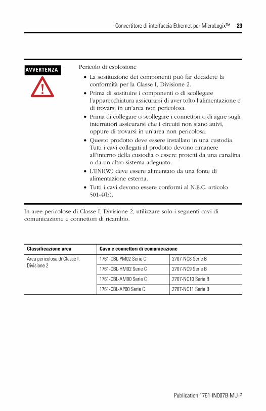
In aree pericolose di Classe I, Divisione 2, utilizzare solo i seguenti cavi di comunicazione e connettori di ricambio.
AVVERTENZA Pericolo di esplosione
• La sostituzione dei componenti può far decadere la conformità per la Classe I, Divisione 2.
• Prima di sostituire i componenti o di scollegare l’apparecchiatura assicurarsi di aver tolto l’alimentazione e di trovarsi in un’area non pericolosa.
• Prima di collegare o scollegare i connettori o di agire sugli interruttori assicurarsi che i circuiti non siano attivi, oppure di trovarsi in un’area non pericolosa.
• Questo prodotto deve essere installato in una custodia. Tutti i cavi collegati al prodotto devono rimanere all’interno della custodia o essere protetti da una canalina o da un altro sistema adeguato.
• L’ENI(W) deve essere alimentato da una fonte di alimentazione esterna.
• Tutti i cavi devono essere conformi al N.E.C. articolo 501-4(b).
Classificazione area Cavo e connettori di comunicazione
Area pericolosa di Classe I, Divisione 2
1761-CBL-PM02 Serie C 2707-NC8 Serie B
1761-CBL-HM02 Serie C 2707-NC9 Serie B
1761-CBL-AM00 Serie C 2707-NC10 Serie B
1761-CBL-AP00 Serie C 2707-NC11 Serie B
Publication 1761-IN007B-MU-P
24 Convertitore di interfaccia Ethernet per MicroLogix™
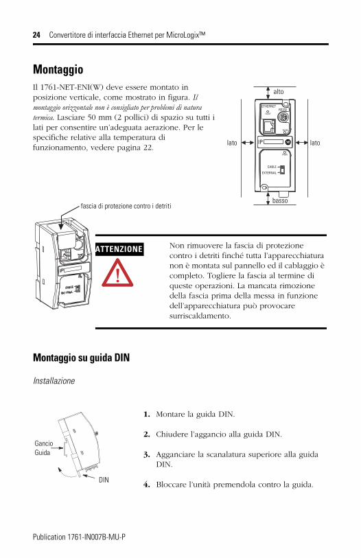
MontaggioIl 1761-NET-ENI(W) deve essere montato in posizione verticale, come mostrato in figura. Il montaggio orizzontale non è consigliato per problemi di natura termica. Lasciare 50 mm (2 pollici) di spazio su tutti i lati per consentire un’adeguata aerazione. Per le specifiche relative alla temperatura di funzionamento, vedere pagina 22.
Montaggio su guida DIN
Installazione
ETHERNET
FAULT
RS232
TX/RX
PWR
CABLE
EXTERNAL
IP
alto
basso
lato lato
fascia di protezione contro i detriti
ATTENZIONE Non rimuovere la fascia di protezione contro i detriti finché tutta l’apparecchiatura non è montata sul pannello ed il cablaggio è completo. Togliere la fascia al termine di queste operazioni. La mancata rimozione della fascia prima della messa in funzione dell’apparecchiatura può provocare surriscaldamento.
GancioGuida
DIN
1. Montare la guida DIN.
2. Chiudere l’aggancio alla guida DIN.
3. Agganciare la scanalatura superiore alla guida DIN.
4. Bloccare l’unità premendola contro la guida.
Publication 1761-IN007B-MU-P
Convertitore di interfaccia Ethernet per MicroLogix™ 25
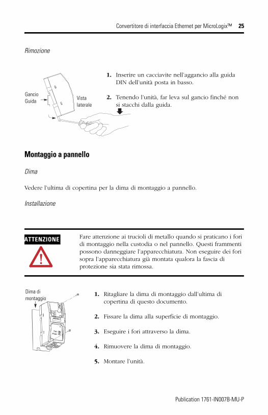
Rimozione
Montaggio a pannello
Dima
Vedere l’ultima di copertina per la dima di montaggio a pannello.
Installazione
ATTENZIONE Fare attenzione ai trucioli di metallo quando si praticano i fori di montaggio nella custodia o nel pannello. Questi frammenti possono danneggiare l’apparecchiatura. Non eseguire dei fori sopra l’apparecchiatura già montata qualora la fascia di protezione sia stata rimossa.
1. Inserire un cacciavite nell’aggancio alla guida DIN dell’unità posta in basso.
2. Tenendo l’unità, far leva sul gancio finché non si stacchi dalla guida.
GancioGuida Vista
laterale
1. Ritagliare la dima di montaggio dall’ultima di copertina di questo documento.
2. Fissare la dima alla superficie di montaggio.
3. Eseguire i fori attraverso la dima.
4. Rimuovere la dima di montaggio.
5. Montare l’unità.
Dima di montaggio
Publication 1761-IN007B-MU-P
26 Convertitore di interfaccia Ethernet per MicroLogix™
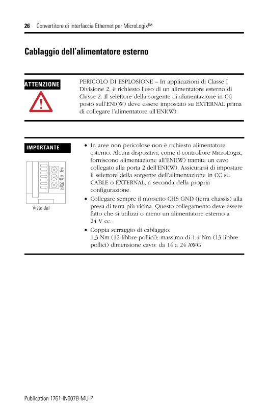
Cablaggio dell’alimentatore esterno
ATTENZIONE PERICOLO DI ESPLOSIONE – In applicazioni di Classe I Divisione 2, è richiesto l’uso di un alimentatore esterno di Classe 2. Il selettore della sorgente di alimentazione in CC posto sull’ENI(W) deve essere impostato su EXTERNAL prima di collegare l’alimentatore all’ENI(W).
IMPORTANTE • In aree non pericolose non è richiesto alimentatore esterno. Alcuni dispositivi, come il controllore MicroLogix, forniscono alimentazione all’ENI(W) tramite un cavo collegato alla porta 2 dell’ENI(W). Assicurarsi di impostare il selettore della sorgente dell’alimentazione in CC su CABLE o EXTERNAL, a seconda della propria configurazione.
• Collegare sempre il morsetto CHS GND (terra chassis) alla presa di terra più vicina. Questo collegamento deve essere fatto che si utilizzi o meno un alimentatore esterno a 24 V cc.
• Coppia serraggio di cablaggio: 1,3 Nm (12 libbre pollici); massimo di 1,4 Nm (13 libbre pollici) dimensione cavo: da 14 a 24 AWG
VDC24
DCNEUT
CHSGND
Vista dal
Publication 1761-IN007B-MU-P
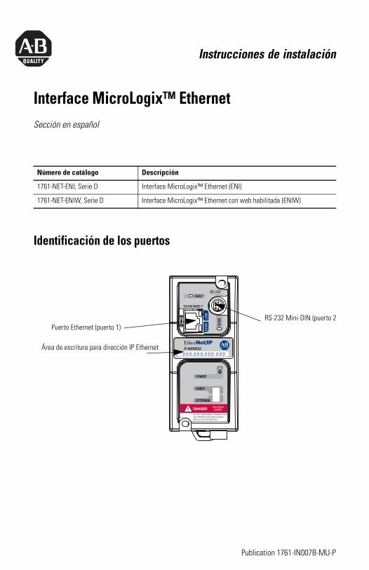
Instrucciones de instalación
Interface MicroLogix™ EthernetSección en español
Identificación de los puertos
Número de catálogo Descripción
1761-NET-ENI, Serie D Interface MicroLogix™ Ethernet (ENI)
1761-NET-ENIW, Serie D Interface MicroLogix™ Ethernet con web habilitada (ENIW)
Área de escritura para dirección IP Ethernet
RS-232 Mini-DIN (puerto 2Puerto Ethernet (puerto 1)
Publication 1761-IN007B-MU-P
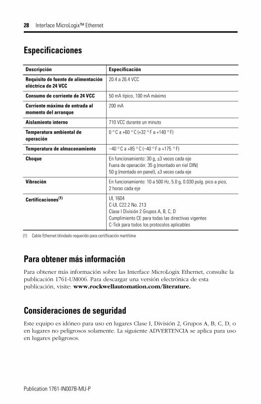
28 Interface MicroLogix™ Ethernet
Especificaciones
Para obtener más informaciónPara obtener más información sobre las Interface MicroLogix Ethernet, consulte la publicación 1761-UM006. Para descargar una versión electrónica de esta publicación, visite: www.rockwellautomation.com/literature.
Consideraciones de seguridadEste equipo es idóneo para uso en lugares Clase I, División 2, Grupos A, B, C, D, o en lugares no peligrosos solamente. La siguiente ADVERTENCIA se aplica para uso en lugares peligrosos.
Descripción Especificación
Requisito de fuente de alimentación eléctrica de 24 VCC
20.4 a 26.4 VCC
Consumo de corriente de 24 VCC 50 mA típico, 100 mA máximo
Corriente máxima de entrada al momento del arranque
200 mA
Aislamiento interno 710 VCC durante un minuto
Temperatura ambiental de operación
0 ° C a +60 ° C (+32 ° F a +140 ° F)
Temperatura de almacenamiento –40 ° C a +85 ° C (–40 ° F a +175 ° F)
Choque En funcionamiento: 30 g, ±3 veces cada ejeFuera de operación: 35 g (montado en riel DIN) 50 g (montado en panel), ±3 veces cada eje
Vibración En funcionamiento: 10 a 500 Hz, 5.0 g, 0.030 pulg. pico a pico, 2 horas cada eje
Certificaciones(1)
(1) Cable Ethernet blindado requerido para certificación martítima
UL 1604C-UL C22.2 No. 213 Clase I División 2 Grupos A, B, C, D Cumplimiento CE para todas las directivas vigentesC-Tick para todos los protocolos aplicables
Publication 1761-IN007B-MU-P
Interface MicroLogix™ Ethernet 29
Use sólo los siguientes cables de comunicación y conectores de repuesto en lugares peligrosos Clase I, División 2.
ADVERTENCIA Peligro de explosión
• La sustitución de componentes puede modificar la idoneidad para uso en Clase I, División 2.
• No reemplace componentes ni desconecte el equipo a menos que se haya desconectado la alimentación eléctrica y el área se considere no peligrosa.
• No conecte ni desconecte conectores, ni haga funcionar interruptores con el circuito activo, a menos que el área se considere no peligrosa.
• Este producto debe instalarse en un envolvente. Todos los cables conectados al producto deben encontrarse dentro del envolvente o contar con protección de canaleta u otras medidas de protección.
• Se debe usar una fuente de alimentación eléctrica externa para hacer funcionar la ENI(W).
• Todo el cableado debe cumplir con las especificaciones de N.E.C. artículo 501-4(b).
Clasificación de ambiente Cable y conectores de comunicación
Ambiente peligroso de Clase I, División 2
1761-CBL-PM02 Serie C 2707-NC8 Serie B
1761-CBL-HM02 Serie C 2707-NC9 serie B
1761-CBL-AM00 serie C 2707-NC10 serie B
1761-CBL-AP00 Serie C 2707-NC11 Serie B
Publication 1761-IN007B-MU-P
30 Interface MicroLogix™ Ethernet
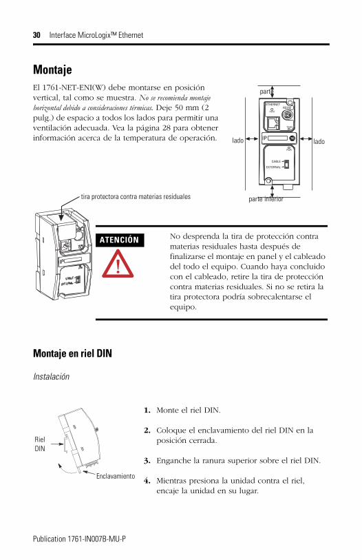
MontajeEl 1761-NET-ENI(W) debe montarse en posición vertical, tal como se muestra. No se recomienda montaje horizontal debido a consideraciones térmicas. Deje 50 mm (2 pulg.) de espacio a todos los lados para permitir una ventilación adecuada. Vea la página 28 para obtener información acerca de la temperatura de operación.
Montaje en riel DIN
Instalación
ETHERNET
FAULT
RS232
TX/RX
PWR
CABLE
EXTERNAL
IP
parte
parte inferior
lado lado
tira protectora contra materias residuales
ATENCIÓN No desprenda la tira de protección contra materias residuales hasta después de finalizarse el montaje en panel y el cableado del todo el equipo. Cuando haya concluido con el cableado, retire la tira de protección contra materias residuales. Si no se retira la tira protectora podría sobrecalentarse el equipo.
RielDIN
Enclavamiento
1. Monte el riel DIN.
2. Coloque el enclavamiento del riel DIN en la posición cerrada.
3. Enganche la ranura superior sobre el riel DIN.
4. Mientras presiona la unidad contra el riel, encaje la unidad en su lugar.
Publication 1761-IN007B-MU-P
Interface MicroLogix™ Ethernet 31
Extracción
Montaje en panel
Plantilla
Vea la cubierta posterior para obtener la plantilla de montaje en panel.
Instalación
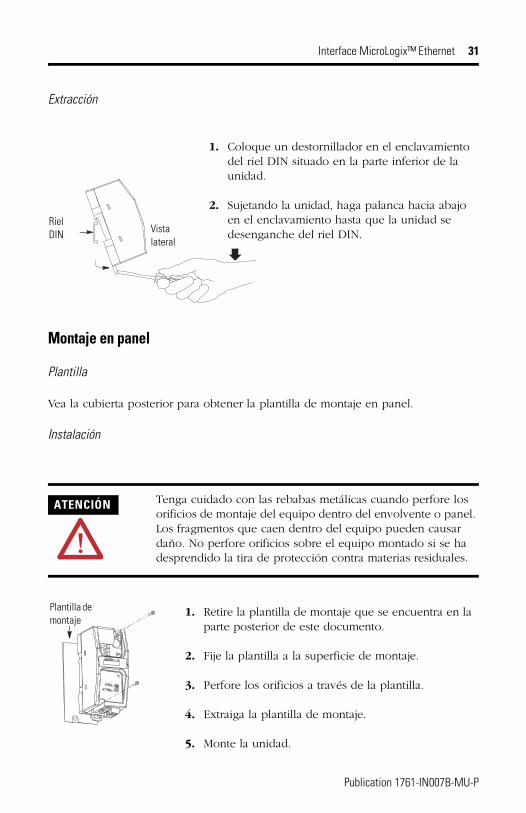
ATENCIÓN Tenga cuidado con las rebabas metálicas cuando perfore los orificios de montaje del equipo dentro del envolvente o panel. Los fragmentos que caen dentro del equipo pueden causar daño. No perfore orificios sobre el equipo montado si se ha desprendido la tira de protección contra materias residuales.
1. Coloque un destornillador en el enclavamiento del riel DIN situado en la parte inferior de la unidad.
2. Sujetando la unidad, haga palanca hacia abajo en el enclavamiento hasta que la unidad se desenganche del riel DIN.
RielDIN Vista
lateral
1. Retire la plantilla de montaje que se encuentra en la parte posterior de este documento.
2. Fije la plantilla a la superficie de montaje.
3. Perfore los orificios a través de la plantilla.
4. Extraiga la plantilla de montaje.
5. Monte la unidad.
Plantilla de montaje
Publication 1761-IN007B-MU-P
32 Interface MicroLogix™ Ethernet
Cableado de la fuente de alimentación externa
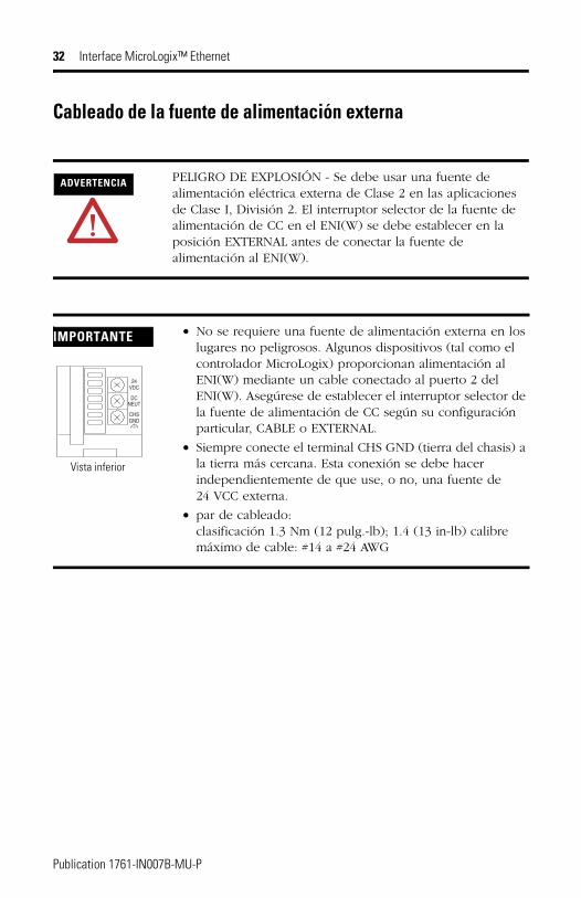
ADVERTENCIA PELIGRO DE EXPLOSIÓN - Se debe usar una fuente de alimentación eléctrica externa de Clase 2 en las aplicaciones de Clase I, División 2. El interruptor selector de la fuente de alimentación de CC en el ENI(W) se debe establecer en la posición EXTERNAL antes de conectar la fuente de alimentación al ENI(W).
IMPORTANTE • No se requiere una fuente de alimentación externa en los lugares no peligrosos. Algunos dispositivos (tal como el controlador MicroLogix) proporcionan alimentación al ENI(W) mediante un cable conectado al puerto 2 del ENI(W). Asegúrese de establecer el interruptor selector de la fuente de alimentación de CC según su configuración particular, CABLE o EXTERNAL.
• Siempre conecte el terminal CHS GND (tierra del chasis) a la tierra más cercana. Esta conexión se debe hacer independientemente de que use, o no, una fuente de 24 VCC externa.
• par de cableado: clasificación 1.3 Nm (12 pulg.-lb); 1.4 (13 in-lb) calibre máximo de cable: #14 a #24 AWG
VDC24
DCNEUT
CHSGND
Vista inferior
Publication 1761-IN007B-MU-P

Instruções de Instalação
Conversor de Interface Ethernet Micrologix™Seção em Português
Identificação da Porta
Código de Catálogo Descrição
1761-NET-ENI, Série D Interface Ethernet MicroLogix™ (ENI)
1761-NET-ENIW, Série D Interface Ethernet MicroLogix™ Habilitada pela Web (ENIW)
Área de escrita do endereço IP da Ethernet
Mini-DIN RS-232 (Porta 2)Porta Ethernet (Porta 1)
Publication 1761-IN007B-MU-P
34 Conversor de Interface Ethernet Micrologix™
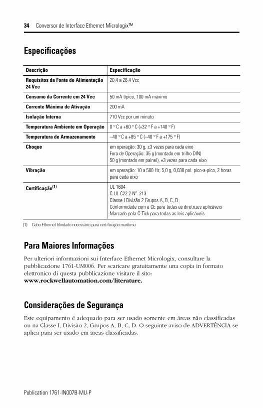
Especificações
Para Maiores InformaçõesPer ulteriori informazioni sui Interface Ethernet Micrologix, consultare la pubblicazione 1761-UM006. Per scaricare gratuitamente una copia in formato elettronico di questa pubblicazione visitare il sito: www.rockwellautomation.com/literature.
Considerações de SegurançaEste equipamento é adequado para ser usado somente em áreas não classificadas ou na Classe I, Divisão 2, Grupos A, B, C, D. O seguinte aviso de ADVERTÊNCIA se aplica para ser usado em áreas classificadas.
Descrição Especificação
Requisitos da Fonte de Alimentação 24 Vcc
20,4 a 26,4 Vcc
Consumo da Corrente em 24 Vcc 50 mA típico, 100 mA máximo
Corrente Máxima de Ativação 200 mA
Isolação Interna 710 Vcc por um minuto
Temperatura Ambiente em Operação 0 ° C a +60 ° C (+32 ° F a +140 ° F)
Temperatura de Armazenamento –40 ° C a +85 ° C (–40 ° F a +175 ° F)
Choque em operação: 30 g, ±3 vezes para cada eixoFora de Operação: 35 g (montado em trilho DIN) 50 g (montado em painel), ±3 vezes para cada eixo
Vibração em operação: 10 a 500 Hz, 5,0 g, 0,030 pol. pico-a-pico, 2 horas para cada eixo
Certificação(1)
(1) Cabo Ethernet blindado necessário para certificação marítima
UL 1604C-UL C22.2 Nº. 213Classe I Divisão 2 Grupos A, B, C, DConformidade com a CE para todas as diretrizes aplicáveisMarcado pela C-Tick para todas as leis aplicáveis
Publication 1761-IN007B-MU-P
Conversor de Interface Ethernet Micrologix™ 35
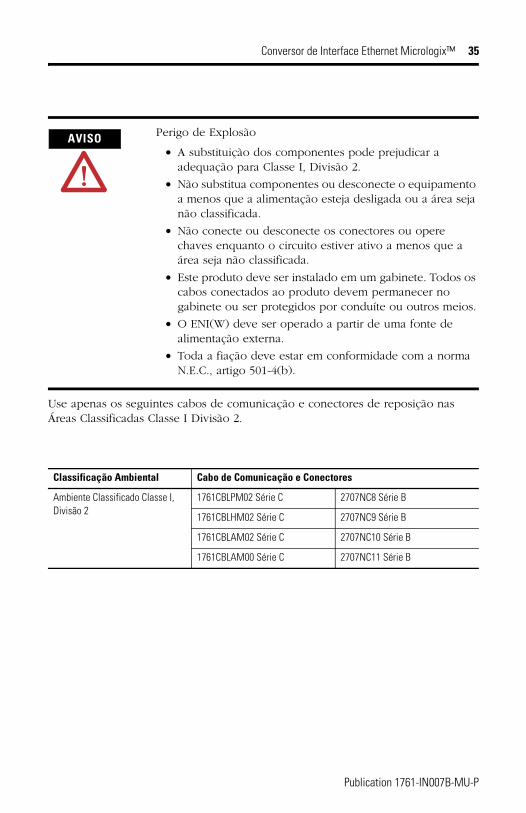
Use apenas os seguintes cabos de comunicação e conectores de reposição nas Áreas Classificadas Classe I Divisão 2.
AVISO Perigo de Explosão
• A substituição dos componentes pode prejudicar a adequação para Classe I, Divisão 2.
• Não substitua componentes ou desconecte o equipamento a menos que a alimentação esteja desligada ou a área seja não classificada.
• Não conecte ou desconecte os conectores ou opere chaves enquanto o circuito estiver ativo a menos que a área seja não classificada.
• Este produto deve ser instalado em um gabinete. Todos os cabos conectados ao produto devem permanecer no gabinete ou ser protegidos por conduíte ou outros meios.
• O ENI(W) deve ser operado a partir de uma fonte de alimentação externa.
• Toda a fiação deve estar em conformidade com a norma N.E.C., artigo 501-4(b).
Classificação Ambiental Cabo de Comunicação e Conectores
Ambiente Classificado Classe I, Divisão 2
1761CBLPM02 Série C 2707NC8 Série B
1761CBLHM02 Série C 2707NC9 Série B
1761CBLAM02 Série C 2707NC10 Série B
1761CBLAM00 Série C 2707NC11 Série B
Publication 1761-IN007B-MU-P
36 Conversor de Interface Ethernet Micrologix™
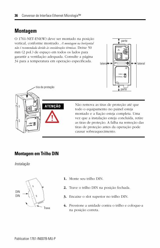
MontagemO 1761-NET-ENI(W) deve ser montado na posição vertical, conforme mostrado. A montagem na horizontal não é recomendada devido às considerações térmicas. Deixe 50 mm (2 pol.) de espaço em todos os lados para garantir a ventilação adequada. Consulte a página 34 para a temperatura em operação especificada.
Montagem em Trilho DIN
Instalação
ETHERNET
FAULT
RS232
TX/RX
PWR
CABLE
EXTERNAL
IP
parte
parte
lateral lateral
tira de proteção
ATENÇÃO Não remova as tiras de proteção até que todo o equipamento no painel esteja montado e a fiação esteja completa. Uma vez que a instalação esteja concluída, retire as tiras de proteção. A falha na remoção das tiras de proteção antes da operação pode causar sobreaquecimento.
DINDIN
Trava
1. Monte seu trilho DIN.
2. Trave o trilho DIN na posição fechada.
3. Encaixe o slot superior no trilho DIN.
4. Pressione a unidade contra o trilho e coloque-a na posição correta.
Publication 1761-IN007B-MU-P
Conversor de Interface Ethernet Micrologix™ 37
Remoção
Montagem em Painel
Gabarito
Consulte a capa de trás para um gabarito de montagem em painel.
Instalação
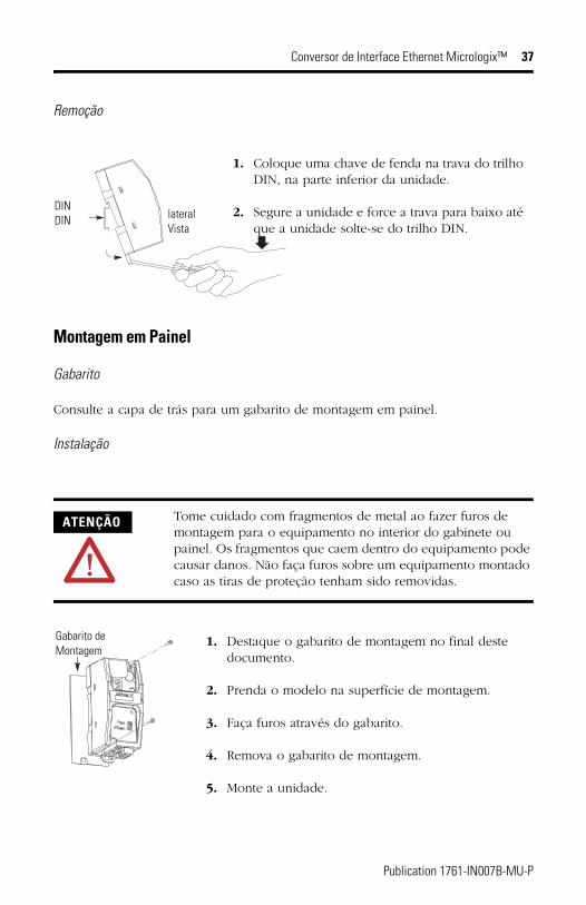
ATENÇÃO Tome cuidado com fragmentos de metal ao fazer furos de montagem para o equipamento no interior do gabinete ou painel. Os fragmentos que caem dentro do equipamento pode causar danos. Não faça furos sobre um equipamento montado caso as tiras de proteção tenham sido removidas.
1. Coloque uma chave de fenda na trava do trilho DIN, na parte inferior da unidade.
2. Segure a unidade e force a trava para baixo até que a unidade solte-se do trilho DIN.
DINDIN lateral
Vista
1. Destaque o gabarito de montagem no final deste documento.
2. Prenda o modelo na superfície de montagem.
3. Faça furos através do gabarito.
4. Remova o gabarito de montagem.
5. Monte a unidade.
Gabarito de Montagem
Publication 1761-IN007B-MU-P
38 Conversor de Interface Ethernet Micrologix™
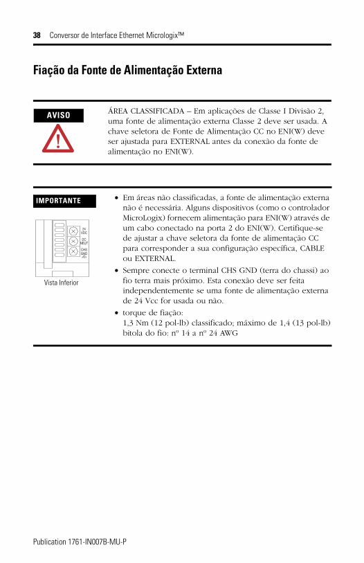
Fiação da Fonte de Alimentação Externa
AVISO ÁREA CLASSIFICADA – Em aplicações de Classe I Divisão 2, uma fonte de alimentação externa Classe 2 deve ser usada. A chave seletora de Fonte de Alimentação CC no ENI(W) deve ser ajustada para EXTERNAL antes da conexão da fonte de alimentação no ENI(W).
IMPORTANTE • Em áreas não classificadas, a fonte de alimentação externa não é necessária. Alguns dispositivos (como o controlador MicroLogix) fornecem alimentação para ENI(W) através de um cabo conectado na porta 2 do ENI(W). Certifique-se de ajustar a chave seletora da fonte de alimentação CC para corresponder a sua configuração específica, CABLE ou EXTERNAL.
• Sempre conecte o terminal CHS GND (terra do chassi) ao fio terra mais próximo. Esta conexão deve ser feita independentemente se uma fonte de alimentação externa de 24 Vcc for usada ou não.
• torque de fiação: 1,3 Nm (12 pol-lb) classificado; máximo de 1,4 (13 pol-lb)bitola do fio: nº 14 a nº 24 AWG
VDC24
DCNEUT
CHSGND
Vista Inferior
Publication 1761-IN007B-MU-P

Publication 1761-IN007B-MU-P - June 2005
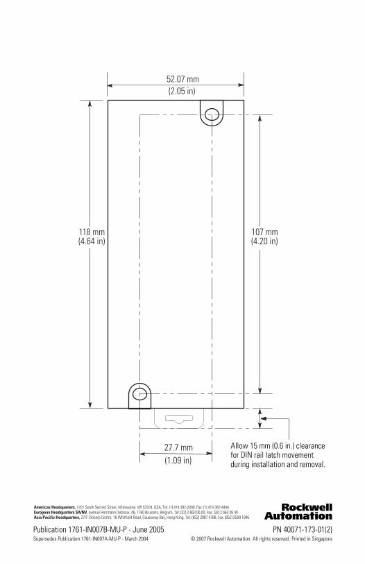
52.07 mm(2.05 in)
27.7 mm(1.09 in)
107 mm(4.20 in)
118 mm(4.64 in)
Allow 15 mm (0.6 in.) clearance for DIN rail latch movement during installation and removal.
Publication 1761-IN007B-MU-P - June 2005 PN 40071-173-01(2)Supersedes Publication 1761-IN007A-MU-P - March 2004 © 2007 Rockwell Automation. All rights reserved. Printed in Singapore.