Embed Size (px)
Citation preview

Installation Instructions
1732E ArmorBlock Dual Port EtherNet/IP 8-Point Digital ModulesCatalog Numbers 1732E-IB8M8SOER, 1732E-OB8M8SR, 1732E-8CFGM8R
Table of Contents
Topic Page
Important User Information 2
Environment and Enclosure 3
Preventing Electrostatic Discharge 3
Overview 4
Catalog Number Explanation 6
Install the Module 6
Set the Network Address 6
Mount the Module 7
Product Dimensions 7
Connect the I/O, Network and Auxiliary Cables to the Module 9
Configure the Module 12
Interpret LED Indicators 15
Specifications 17
2 1732E ArmorBlock Dual Port EtherNet/IP 8-Point Digital Modules
Important User Information
Solid-state equipment has operational characteristics differing from those of electromechanical equipment. Safety Guidelines for the Application, Installation and Maintenance of Solid State Controls (Publication SGI-1.1 available from your local Rockwell Automation sales office or online at http://www.rockwellautomation.com/literature/) describes some important differences between solid-state equipment and hard-wired electromechanical devices. Because of this difference, and also because of the wide variety of uses for solid-state equipment, all persons responsible for applying this equipment must satisfy themselves that each intended application of this equipment is acceptable.
In no event will Rockwell Automation, Inc. be responsible or liable for indirect or consequential damages resulting from the use or application of this equipment.
The examples and diagrams in this manual are included solely for illustrative purposes. Because of the many variables and requirements associated with any particular installation, Rockwell Automation, Inc. cannot assume responsibility or liability for actual use based on the examples and diagrams.
No patent liability is assumed by Rockwell Automation, Inc. with respect to use of information, circuits, equipment, or software described in this manual.
Reproduction of the contents of this manual, in whole or in part, without written permission of Rockwell Automation, Inc., is prohibited.
Throughout this manual, when necessary, we use notes to make you aware of safety considerations.
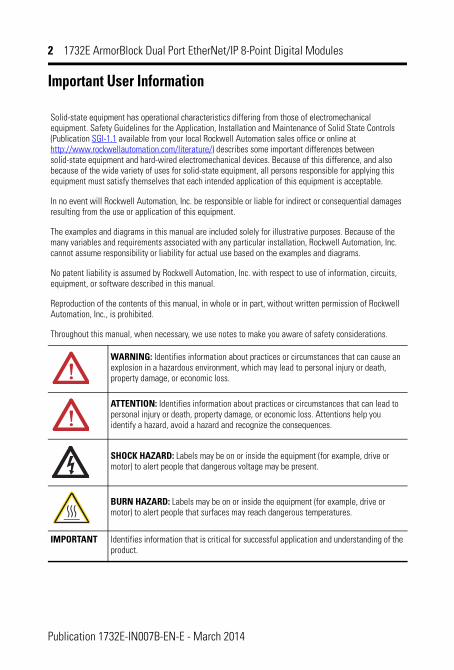
WARNING: Identifies information about practices or circumstances that can cause an explosion in a hazardous environment, which may lead to personal injury or death, property damage, or economic loss.
ATTENTION: Identifies information about practices or circumstances that can lead to personal injury or death, property damage, or economic loss. Attentions help you identify a hazard, avoid a hazard and recognize the consequences.
SHOCK HAZARD: Labels may be on or inside the equipment (for example, drive or motor) to alert people that dangerous voltage may be present.
BURN HAZARD: Labels may be on or inside the equipment (for example, drive or motor) to alert people that surfaces may reach dangerous temperatures.
IMPORTANT Identifies information that is critical for successful application and understanding of the product.
Publication 1732E-IN007B-EN-E - March 2014
1732E ArmorBlock Dual Port EtherNet/IP 8-Point Digital Modules 3
Environment and Enclosure
Preventing Electrostatic Discharge
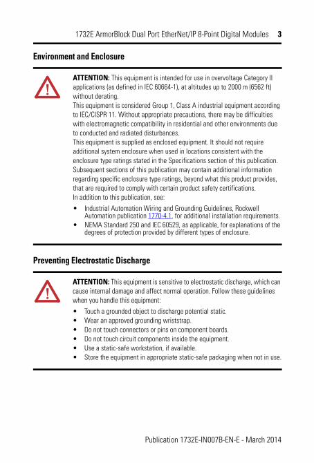
ATTENTION: This equipment is intended for use in overvoltage Category II applications (as defined in IEC 60664-1), at altitudes up to 2000 m (6562 ft) without derating. This equipment is considered Group 1, Class A industrial equipment according to IEC/CISPR 11. Without appropriate precautions, there may be difficulties with electromagnetic compatibility in residential and other environments due to conducted and radiated disturbances. This equipment is supplied as enclosed equipment. It should not require additional system enclosure when used in locations consistent with the enclosure type ratings stated in the Specifications section of this publication. Subsequent sections of this publication may contain additional information regarding specific enclosure type ratings, beyond what this product provides, that are required to comply with certain product safety certifications. In addition to this publication, see:
• Industrial Automation Wiring and Grounding Guidelines, Rockwell Automation publication 1770-4.1, for additional installation requirements.
• NEMA Standard 250 and IEC 60529, as applicable, for explanations of the degrees of protection provided by different types of enclosure.
ATTENTION: This equipment is sensitive to electrostatic discharge, which can cause internal damage and affect normal operation. Follow these guidelines when you handle this equipment:
• Touch a grounded object to discharge potential static.• Wear an approved grounding wriststrap.• Do not touch connectors or pins on component boards.• Do not touch circuit components inside the equipment.• Use a static-safe workstation, if available.• Store the equipment in appropriate static-safe packaging when not in use.
Publication 1732E-IN007B-EN-E - March 2014

4 1732E ArmorBlock Dual Port EtherNet/IP 8-Point Digital Modules
Additional Resources
If you would like a manual, you can:
• download a free electronic version from the internet: http://literature.rockwellautomation.com
• purchase a printed manual by contacting your local Allen-Bradley distributor or Rockwell Automation representative
OverviewThe EtherNet/IP ArmorBlock is a 24V DC I/O module that communicates via EtherNet/IP. The sealed IP65, IP67 and IP69K housing of these modules requires no enclosure. Note that environmental requirements other than IP65, IP67 and IP69K may require an additional appropriate enclosure. I/O connectors are sealed M8 style.
EtherNet/IP networks use advanced network technology, for example, producer/consumer communication, to increase network functionality and throughput.
Resource Description
ArmorBlock™ Dual-Port EtherNet/IP 8-Point Digital Modules Wiring Diagrams 1732E-WD002
Pinout guide wiring diagram for the ArmorBlock dual-port EtherNet/IP 8-Point modules (1732E-IB8M8SOER, 1732E-OB8M8SR, 1732E-8CFGM8R).
1732E ArmorBlock EtherNet/IP Dual Port 8-Point Sequence of Events Input and Scheduled Sourcing Output Modules User Manual 1732E-UM003
A detailed description of module functionality, configuration, installation procedure and information on how to use the ArmorBlock dual-port EtherNet/IP 8-Point digital modules (1732E-IB8M8SOER, 1732E-OB8M8SR).
Industrial Automation Wiring and Grounding Guidelines, publication 1770-4.1
More information on proper wiring and grounding techniques.
Publication 1732E-IN007B-EN-E - March 2014

1732E ArmorBlock Dual Port EtherNet/IP 8-Point Digital Modules 5
Module Identification
(1) Functional Earth grounds the I/O block’s EtherNet/IP communication circuitry which is designed to mitigate the effect of noise on the network. The device requires a solid earth ground connection, either through a metal screw to a grounded metal panel or through a wire. See EtherNet/IP Connector on page 10 for connections.
LINK1
NETMOD
X10
X100X1
LINK2
45766
Link 1 status indicator
Function earth(1)
EtherNet/IP D-code M12 connector
Node address switches
M8 style
I/O connectors
Micro-style power in Micro-style power out
M8 style I/O connectors
EtherNet/IP D-code M12 connector
Link 2 status indicator
Node address switches
Network status indicatorModule status indicator
I/O status indicators
Power status indicator
Publication 1732E-IN007B-EN-E - March 2014
6 1732E ArmorBlock Dual Port EtherNet/IP 8-Point Digital Modules
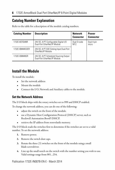
Catalog Number ExplanationRefer to the table for a description of the module catalog numbers.
Install the ModuleTo install the module:
• Set the network address• Mount the module• Connect the I/O, Network and Auxiliary cables to the module.
Set the Network AddressThe I/O block ships with the rotary switches set to 999 and DHCP enabled.
To change the network address, you can do one of the following:
• adjust the switch on the front of the module.• use a Dynamic Host Configuration Protocol (DHCP) server, such as
Rockwell Automation BootP/DHCP.• retrieve the IP address from nonvolatile memory.
The I/O block reads the switches first to determine if the switches are set to a valid number. To set the network address:
1. Remove power.
2. Remove the switch dust caps.
3. Rotate the three (3) switches on the front of the module using a small blade screwdriver.
4. Line up the small notch on the switch with the number setting you wish to use. Valid settings range from 001…254.
Catalog Number Description Network Connector
Power Connector
1732E-8CFGM8R 24V DC, 8-PT Configurable Digital I/O Dual-Port EtherNet/IP Module
Dual D-code M12
Dual 4-pin micro
1732E-IB8M8SOER 24V DC, 8-PT SOE Sinking Input Dual-Port EtherNet/IP Module
1732E-OB8M8SR 24V DC, 8-PT Scheduled Sourcing Output Dual-Port EtherNet/IP Module
Publication 1732E-IN007B-EN-E - March 2014

1732E ArmorBlock Dual Port EtherNet/IP 8-Point Digital Modules 7
5. Replace switch dust caps. Make sure not to over tighten.
6. Reapply power.
Set Network Address
When the switches are set to a valid number, the I/O block’s IP address is 192.168.1.xxx (where xxx represents the number set on the switches). The I/O block’s subnet mask is 255.255.255.0 and the gateway address is set to 0.0.0.0. When the I/O block uses the network address set on the switches, the I/O block does not have a host name assigned to it or use any Domain Name Server.
If the switches are set to an invalid number (for example, 000 or a value greater than 254 excluding 888), the I/O block checks to see if DHCP is enabled. If DHCP is enabled, the I/O block asks for an address from a DHCP server. The DHCP server also assigns other Transport Control Protocol (TCP) parameters.
If DHCP is not enabled, the I/O block uses the IP address (along with other TCP configurable parameters) stored in nonvolatile memory.
Mount the ModuleTwo sets of mounting holes are used to mount the module directly to a panel or machine. Mounting holes accommodate #6 (M3) pan head screws. The torque specification is 0.68 Nm (6 lb-in.).
Product DimensionsRefer to the mounting dimensions illustration to help you mount the module.
0
24
68
0
2
4
68
0
2
4
68
Example shows default node address set at 163.
44233
Note: You need to remove the protective switch dust caps before you can adjust the address settings.
Publication 1732E-IN007B-EN-E - March 2014

8 1732E ArmorBlock Dual Port EtherNet/IP 8-Point Digital Modules
Module Dimensions19.8(0.78)
166.5 (6.56)
27 (1.06)
Side Mounting
32 (1.26 )
43.3 (1.70)
Front Mounting18 (0.71)
37 (1.46)16.2 (0.64)
168.6 (6.64)179 (7.05)
Measurements are in millimeters (inches)
45765
Publication 1732E-IN007B-EN-E - March 2014

1732E ArmorBlock Dual Port EtherNet/IP 8-Point Digital Modules 9
Mount the Module in High Vibration Areas
If you mount the module in an area that is subject to shock or vibration, we recommend you use a flat and a lock washer to mount the module. Mount the flat and the lock washer as shown in the mounting illustration. Torque the mounting screws to 0.68 Nm (6 lb-in.).
High Vibration Area Mounting
Connect the I/O, Network and Auxiliary Cables to the ModuleThe 1732E-8CFGM8R, 1732E-OB8M8SR, 1732E-IB8M8SOER ArmorBlock EtherNet/IP modules have 3-pin pico-style I/O connectors. We provide caps to cover the unused connectors on your module. Connect the quick-disconnect cord sets you selected for your module to the appropriate ports.
I/O Connectors
Pico-style 3-Pin Input Female Connector
45768
Lock washer
Flat washer
43853
(View into connector) Pin 1 Sensor source voltage
Pin 3 Return
Pin 4 Input
Publication 1732E-IN007B-EN-E - March 2014

10 1732E ArmorBlock Dual Port EtherNet/IP 8-Point Digital Modules
Pico-style 3-Pin Output Female Connector
Pico-style 3-Pin Self-Configuring Female Connector
EtherNet/IP Connector
D-Code Micro Network Female Connector
ATTENTION: Sensors/actuators power should not be supplied externally.
43853
(View into connector) Pin 1 Sensor source voltage
Pin 3 Return
Pin 4 Output
43853
(View into connector) Pin 1 Sensor source voltage
Pin 3 Return
Pin 4 Input or Output
(View into connector 1) Pin 1 M12_Tx+
Pin 2 M12_Rx+
Pin 3 M12_Tx- Pin 4 M12_Rx- Pin 5 Connector shell shield GND
4
2
3 1
544808
Publication 1732E-IN007B-EN-E - March 2014

1732E ArmorBlock Dual Port EtherNet/IP 8-Point Digital Modules 11
Self-configuring ModuleThe 1732E-8CFGM8R self-configuring module contains both input and output functionality.
• If an I/O point is to be an output, dedicate that point as an output with a wired load and energize it through a control program.
• Energized outputs show an associated active input that can be used as a feedback mechanism to make certain that the output is on.
• If an I/O point is to be an input, wire the input device as normal and leave the associated output de-energized at all times.
IMPORTANT Use the 1585D–M4DC–H: Polyamide small body unshielded mating connectors for the D-Code M12 female network connector.
Note that the distance between the center of each Ethernet connector is 16.2 mm (see Module Dimensions on page 8). Rockwell Automation recommends the use of suitable cable based on this measurement. Some of the recommended cables are 1585D-M4TBJM-x and 1585D-M4TBDM-x for daisychains.
IMPORTANT Use two twisted pair CAT5E UTP or STP cables.
ATTENTION: Make sure all connectors and caps are securely tightened to properly seal the connections against leaks and maintain IP enclosure type requirements.
D-Code M12 Pin
Wire Color Signal 8-way Modular RJ45 Pin
1 White-orange TX+ 1
2 White-green RX+ 3
3 Orange TX- 2
4 Green RX- 6
Publication 1732E-IN007B-EN-E - March 2014

12 1732E ArmorBlock Dual Port EtherNet/IP 8-Point Digital Modules
I/O Self-configure Circuitry
Configure the ModuleRefer to the illustration for configuration operations.
Turn output on Output circuit
Sensor or actuator
Input circuit
Connector pin
Output scan listInput scan list
Input is on
(or output is on)
From PLC
To PLC
43601
Publication 1732E-IN007B-EN-E - March 2014
1732E ArmorBlock Dual Port EtherNet/IP 8-Point Digital Modules 13
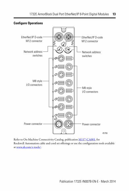
Configure Operations
Refer to On-Machine Connectivity Catalog, publication M117-CA001, for Rockwell Automation cable and cord set offerings or use the configuration tools available at www.ab.com/e-tools/.
LINK1
NETMOD
X10
X100X1
LINK2
45766
EtherNet/IP D-code M12 connector
EtherNet/IP D-code M12 connector
Network address switches
M8 style
I/O connectors
Power connector Power connector
M8 style I/O connectors
Network address switches
Publication 1732E-IN007B-EN-E - March 2014

14 1732E ArmorBlock Dual Port EtherNet/IP 8-Point Digital Modules
Power Connectors
Attach the micro-style 4-pin connector to the micro-style 4-pin receptacle as shown below.
Micro-style 4-Pin Input Male Receptacle
The power required by the module is based on a 4-pin micro-style connector system. The module receives its required power through the male connector on the left. A female connector on the right is also provided so that power can be daisy-chained from module to module.
All three modules require two 24V DC (nominal) supplies. These supplies are called the Module Power and the Auxiliary Power. The Module power powers the microprocessor and Ethernet portions of the module. The Auxiliary Power provides power for the Digital Outputs, the Digital Inputs, and the Sensor Voltage.
Internally, the Module Power and Auxiliary Power are isolated from each other.
IMPORTANT The maximum current that any pin on the power connectors can carry is 4 A.
ATTENTION: To comply with the CE Low Voltage Directive (LVD), this equipment and all connected I/O must be powered from a source compliant with the following: Safety Extra Low Voltage (SELV) or Protected Extra Low Voltage (PELV).
ATTENTION: To comply with UL restrictions, this equipment must be powered from a source compliant with the following: Limited Voltage.
ATTENTION: The device meets UL Type 1 Enclosure rating.
1
4
3
2
Male Input Female Output
(View into receptacle) Pin 1 Auxiliary power+
Pin 2 Module power+
Pin 3 Module power- Pin 4 Auxiliary power-
45764
3
4
1
2
45763
Publication 1732E-IN007B-EN-E - March 2014

1732E ArmorBlock Dual Port EtherNet/IP 8-Point Digital Modules 15
Interpret LED IndicatorsThis module has the following indicators:
• Network, Module, and Link status indicators for EtherNet/IP• Power status indicator• Individual I/O status indicators for inputs and outputs
Status Indicators
LINK1
NETMOD
X10
X100X1
LINK2
Link 2 status indicator
Network status indicator
45766
Module status indicator
I/O status indicators
Power status indicator
Link 1 status indicator
Publication 1732E-IN007B-EN-E - March 2014

16 1732E ArmorBlock Dual Port EtherNet/IP 8-Point Digital Modules
Indicator Status for Modules
Indicator Status Description
Module status Off No power applied to the device.
Flashing red/green The module is performing POST (Power-On Self Test), which completes within 30 s.
Green Device operating normally.
Flashing red Module has experienced a recoverable fault.
Red Unrecoverable fault – may require device replacement.
Flashing green On 1732E-IB8M8SOER and 1732E-OB8M8SR: Device is not synchronized to master clock.
On 1732E-8CFGM8R: Module has not yet been configured.
Network status Off The device is not initialized or the module does not have an IP address.
Flashing green The device has no CIP connections. The device has an IP address, but no CIP connections are established.
Green The device is online, has an IP address, and CIP connections are established.
Flashing red One or more connections have timed out.
Red The module has detected that its IP address is already in use.
Flashing red/green The module is performing a power-on self test (POST).
Network link status (Link 1/Link 2)
Off No link established.
Green Link established on indicated port at 100 Mbps.
Flashing green Link activity present on indicated port at 100 Mbps.
Yellow Link established on indicated port at 10 Mbps.
Flashing yellow Link activity present on indicated port at 10 Mbps.
Power status Off No power to device or input not valid.
Green Power applied to device.
I/O status Off Output/input not energized.
Yellow Output/input energized.
Publication 1732E-IN007B-EN-E - March 2014

1732E ArmorBlock Dual Port EtherNet/IP 8-Point Digital Modules 17
Specifications
IMPORTANT The Module Status LED indicator will flash red and green for a maximum 30 s while the module completes its POST (Power-On Self Test).
General Specifications
Attributes Value
Voltage, power, max 30V DC
Voltage, power, min 12V DC
Current, Module Power, max per module 300 mA @ 24V DC
Current, Auxiliary Power, module only (no Digital Output loads, no Sensor Voltage Loads, and no power daisy-chain loads)
25 mA @ 24V DC
Current, Auxiliary Power, max per module (module plus Digital Output Loads, plus Sensor Voltage Loads, plus power daisy-chain loads)
4A @ 24V DC
Isolation voltage Type tested @ 707V DC for 60s
Communication rate EtherNet/IP
10/100 Mbps
Full or half-duplex
100 meter per segment
Status indicators Module status – red/green
Network status – red/green
Link status – green/yellow
Power status – green
I/O LED – yellow
Dimensions, approx., HxWxD 179 x 37 x 27 mm (7.05 x 1.46 x 1.06 in.)
Pilot Duty Rating DC-14
Weight, approx. 0.34 kg (0.75 lb)
Wiring category(1)
(1) Use this Conductor Category information for planning conductor routing. Refer to publication 1770-4.1, Industrial Automation Wiring and Grounding Guidelines.
1 – on signal ports
1 – on power ports
1 – on communication ports
Publication 1732E-IN007B-EN-E - March 2014

18 1732E ArmorBlock Dual Port EtherNet/IP 8-Point Digital Modules
Input Specifications – 1732E-8CFGM8R, 1732E-IB8M8SOER
Attributes Value
Number of inputs 8 Sink Type
On-state voltage 11V DC, min
24V DC, nom
30V DC, max
Off-state voltage, max 5V DC
On-state current, min 180 µA @ 11V DC
On-state current, max 5.0 mA @ 30V DC
Off-state current, max 90 µA @ 5V DC
Voltage sensor source, max 30V DC
Voltage sensor source, min 10V DC
Input filter 0 ms (default), 2 ms, 4 ms, 8 ms, and 16 ms
Output Specifications – 1732E-8CFGM8R, 1732E-OB8M8SR
Attributes Value
Number of outputs 8 sourcing type
On-state voltage 11V DC, min
24V DC, nom
30V DC, max
On-state current 0.5 A per output, up to 4 A per module
Leakage current, off-state output, max
50 µA
Pilot Duty Rating DC-14
Surge current per output, max 1.2 A for 10 ms, repeatable every 2 s
Publication 1732E-IN007B-EN-E - March 2014

1732E ArmorBlock Dual Port EtherNet/IP 8-Point Digital Modules 19
Environmental Specifications
Attribute Value
Temperature, operating
IEC 60068-2-1 (Test Ad, Operating Cold), IEC 60068-2-2 (Test Bd, Operating Dry Heat), IEC 60068-2-14 (Test Nb, Operating Thermal Shock): -20…60 °C (-4…140 °F)
Temperature, nonoperating
IEC 60068-2-1 (Test Ab, Unpackaged Nonoperating Cold), IEC 60068-2-2 (Test Bb, Unpackaged Nonoperating Dry Heat), IEC 60068-2-14 (Test Na, Unpackaged Nonoperating Thermal Shock): -40…85 °C (-40…185 °F)
Temperature, ambient, max
60 °C (140 °F)
Relative humidity IEC 60068-2-30 (Test Db, Unpackaged Damp Heat): 5…95% noncondensing
Vibration IEC60068-2-6 (Test Fc, Operating): 5 g @ 10…500 Hz
Shock, operating IEC60068-2-27 (Test Ea, Unpackaged Shock): 30 g
Shock, nonoperating IEC60068-2-27 (Test Ea, Unpackaged Shock): 50 g
Emissions CISPR 11: Group 1, Class A
ESD immunity IEC 61000-4-2: 6 kV contact discharges
8 kV air discharges
Radiated RF immunity IEC 61000-4-3: 10V/m with 1 kHz sine-wave 80% AM from 80…2000 MHz 10V/m with 200 Hz 50% Pulse 100% AM @ 900 MHz 10V/m with 200 Hz 50% Pulse 100% AM @ 1890 MHz 1V/m with 1 kHz sine-wave 80% AM from 2000…2700 MHz
EFT/B immunity IEC 61000-4-4: ±3 kV at 5 kHz on power ports
±3 kV at 5 kHz on signal ports
±3 kV at 5 kHz on communication ports
Surge transient immunity
IEC 61000-4-5: ±2 kV line-line(DM) and ±2 kV line-earth(CM) on power ports
±1 kV line-line(DM) and ±2 kV line-earth(CM) on signal ports
±2 kV line-earth(CM) on shielded ports
±2 kV line-earth(CM) on communication ports
Conducted RF immunity
IEC 61000-4-6: 10V rms with 1 kHz sine-wave 80% AM from 150 kHz…80 MHz
Enclosure type rating Meets IP65/66/67/69K (when marked)
Publication 1732E-IN007B-EN-E - March 2014

Allen-Bradley, Rockwell Automation, ArmorBlock, and TechConnect are trademarks of Rockwell Automation, Inc.
Certifications
Certification (when product is marked)(1)
(1) See the Product Certification link at http://www.rockwellautomation.com/products/certification/ for Declarations of Conformity, Certificates, and other certification details.
Value
c-UR-us UL Recognized Component Industrial Control Equipment, certified for US and Canada. See UL File E322657.
CE European Union 2004/108/EC EMC Directive, compliant with: EN 61326-1; Meas./Control/Lab., Industrial Requirements
EN 61000-6-2; Industrial Immunity
EN 61000-6-4; Industrial Emissions
EN 61131-2; Programmable Controllers (Clause 8, Zone A & B)
C-Tick Australian Radiocommunications Act, compliant with: AS/NZS CISPR 11; Industrial Emissions
KC Korean Registration of Broadcasting and Communications
Equipment, compliant with: Article 58-2 of Radio Waves Act, Clause 3
EtherNet/IP ODVA conformance tested to EtherNet/IP specifications.
Publication 1732E-IN007B-EN-E - March 2014 Supersedes Publication 1732E-IN007A-EN-E - January 2012 Copyright © 2014 Rockwell Automation, Inc. All rights reserved.
Trademarks not belonging to Rockwell Automation are property of their respective companies.