Embed Size (px)
Citation preview
8/3/2019 160.67-PR1 - Advances in Steam Cooling ASHRAE
http://slidepdf.com/reader/full/16067-pr1-advances-in-steam-cooling-ashrae 1/4
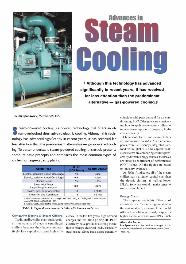
team-powered cooling is a proven technology that offers an of-
ten-overlooked alternative to electric cooling. Although this tech-
nology has advanced significantly in recent years, it has received far less attention than the predominant alternative — gas-powered cool-
ing. To better understand steam-powered cooling, this article presents
some its basic precepts and compares the most common types of
chillers for large-capacity plants.
ciency. In the last few years, high demand
charges and real-time pricing (RTP) of
electricity have provided a strong incen-
tive to manage electrical loads, especially
peak usage. Since peak usage generally
coincides with peak demand for air con-
ditioning, HVAC designers are consider-
ing how to apply non-electric chillers to
reduce consumption of on-peak, high-
cost electricity.
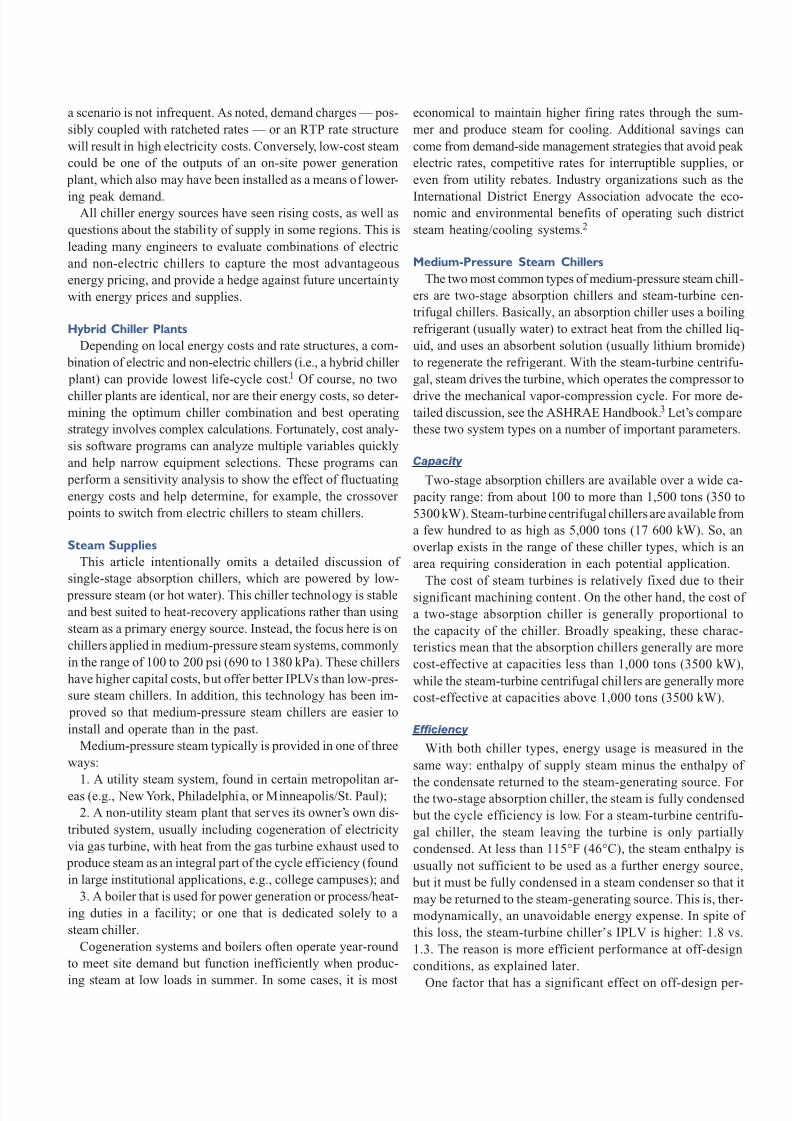
Choices of electric and steam chillers
are summarized in Table 1, which com-
pares overall efficiency (integrated part-
load value [IPLV]) and capital cost.
Because we are comparing chillers pow-
ered by different energy sources, the IPLVs
are stated as coefficient-of-performance
(COP) values. All the figures are based
on industry averages.
As Table 1 indicates, all of the steam
chillers carry a higher capital cost than
the electric chillers, as well as lower
IPLVs. So, when would it make sense touse a steam chiller?
Energy Costs
The simple answer is this: if the cost of
electricity is sufficiently high relative to
the cost of steam, a steam chiller could
offer a lower life-cycle cost, despite its
higher capital cost and lower IPLV. Such
About the Author
Ian Spanswick is the product manager of the
Applied Chiller Group at York International Corp.,
York, Pa.
By Ian Spanswick, Member ASHRAE
Comparing Electric & Steam Chillers
Traditionally, chiller plants in large fa-
cilities consist of electric centrifugal
chillers because they have compara-
tively low capital cost and high effi-
SSSSS
Although this technology has advanced
significantly in recent years, it has received
far less attention than the predominant
alternative — gas-powered cooling.
‘‘‘‘‘
’’’’’
ep y TrellihCV LPI a
)sisaBPOC(tsoClatipaC ∆∆∆∆∆
b
laguf irtneCdeepS-tnatsnoC,cirtcelE 0.7 esaB
laguf irtneCdeepS-elbairaV,cirtcelE 9.9 %52+
wercScirtcelE 5.7 %0+
,retaW-toH /maetSnoitprosb AegatS-elgniS
8.0 %53+
noitprosb AegatS-owT,maetS 3.1 %022+
laguf irtneCenibruT-maetS 8.1 %012+
Table 1: Typical water-cooled chiller efficiencies and costs.
a. IPLV values are calculated according to Air-Conditioning and Refrigeration Institute Stan-dards 560-2000 and 550/590-1998.b. Capital Cost ∆ includes the chiller, pumps and tower, but not the boiler.
8/3/2019 160.67-PR1 - Advances in Steam Cooling ASHRAE
http://slidepdf.com/reader/full/16067-pr1-advances-in-steam-cooling-ashrae 2/4
a scenario is not infrequent. As noted, demand charges — pos-
sibly coupled with ratcheted rates — or an RTP rate structure
will result in high electricity costs. Conversely, low-cost steam
could be one of the outputs of an on-site power generation
plant, which also may have been installed as a means of lower-
ing peak demand.All chiller energy sources have seen rising costs, as well as
questions about the stability of supply in some regions. This is
leading many engineers to evaluate combinations of electric
and non-electric chillers to capture the most advantageous
energy pricing, and provide a hedge against future uncertainty
with energy prices and supplies.
Hybrid Chiller Plants
Depending on local energy costs and rate structures, a com-
bination of electric and non-electric chillers (i.e., a hybrid chiller
plant) can provide lowest life-cycle cost.1 Of course, no two
chiller plants are identical, nor are their energy costs, so deter-mining the optimum chiller combination and best operating
strategy involves complex calculations. Fortunately, cost analy-
sis software programs can analyze multiple variables quickly
and help narrow equipment selections. These programs can
perform a sensitivity analysis to show the effect of fluctuating
energy costs and help determine, for example, the crossover
points to switch from electric chillers to steam chillers.
Steam Supplies
This article intentionally omits a detailed discussion of
single-stage absorption chillers, which are powered by low-
pressure steam (or hot water). This chiller technology is stable
and best suited to heat-recovery applications rather than using
steam as a primary energy source. Instead, the focus here is on
chillers applied in medium-pressure steam systems, commonly
in the range of 100 to 200 psi (690 to 1380 kPa). These chillers
have higher capital costs, but offer better IPLVs than low-pres-
sure steam chillers. In addition, this technology has been im-
proved so that medium-pressure steam chillers are easier to
install and operate than in the past.
Medium-pressure steam typically is provided in one of three
ways:
1. A utility steam system, found in certain metropolitan ar-eas (e.g., New York, Philadelphia, or Minneapolis/St. Paul);
2. A non-utility steam plant that serves its owner’s own dis-
tributed system, usually including cogeneration of electricity
via gas turbine, with heat from the gas turbine exhaust used to
produce steam as an integral part of the cycle efficiency (found
in large institutional applications, e.g., college campuses); and
3. A boiler that is used for power generation or process/heat-
ing duties in a facility; or one that is dedicated solely to a
steam chiller.
Cogeneration systems and boilers often operate year-round
to meet site demand but function inefficiently when produc-
ing steam at low loads in summer. In some cases, it is most
economical to maintain higher firing rates through the sum-
mer and produce steam for cooling. Additional savings can
come from demand-side management strategies that avoid peak
electric rates, competitive rates for interruptible supplies, or
even from utility rebates. Industry organizations such as the
International District Energy Association advocate the eco-nomic and environmental benefits of operating such district
steam heating/cooling systems.2
Medium-Pressure Steam Chillers
The two most common types of medium-pressure steam chill-
ers are two-stage absorption chillers and steam-turbine cen-
trifugal chillers. Basically, an absorption chiller uses a boiling
refrigerant (usually water) to extract heat from the chilled liq-
uid, and uses an absorbent solution (usually lithium bromide)
to regenerate the refrigerant. With the steam-turbine centrifu-
gal, steam drives the turbine, which operates the compressor to
drive the mechanical vapor-compression cycle. For more de-tailed discussion, see the ASHRAE Handbook.3 Let’s compare
these two system types on a number of important parameters.
Capacity
Two-stage absorption chillers are available over a wide ca-
pacity range: from about 100 to more than 1,500 tons (350 to
5300 kW). Steam-turbine centrifugal chillers are available from
a few hundred to as high as 5,000 tons (17 600 kW). So, an
overlap exists in the range of these chiller types, which is an
area requiring consideration in each potential application.
The cost of steam turbines is relatively fixed due to their
significant machining content. On the other hand, the cost of
a two-stage absorption chiller is generally proportional to
the capacity of the chiller. Broadly speaking, these charac-
teristics mean that the absorption chillers generally are more
cost-effective at capacities less than 1,000 tons (3500 kW),
while the steam-turbine centrifugal chillers are generally more
cost-effective at capacities above 1,000 tons (3500 kW).
Efficiency
With both chiller types, energy usage is measured in the
same way: enthalpy of supply steam minus the enthalpy of
the condensate returned to the steam-generating source. For the two-stage absorption chiller, the steam is fully condensed
but the cycle efficiency is low. For a steam-turbine centrifu-
gal chiller, the steam leaving the turbine is only partially
condensed. At less than 115°F (46°C), the steam enthalpy is
usually not sufficient to be used as a further energy source,
but it must be fully condensed in a steam condenser so that it
may be returned to the steam-generating source. This is, ther-
modynamically, an unavoidable energy expense. In spite of
this loss, the steam-turbine chiller’s IPLV is higher: 1.8 vs.
1.3. The reason is more efficient performance at off-design
conditions, as explained later.
One factor that has a significant effect on off-design per-
8/3/2019 160.67-PR1 - Advances in Steam Cooling ASHRAE
http://slidepdf.com/reader/full/16067-pr1-advances-in-steam-cooling-ashrae 3/4
of steam involves more piping connections (steam supply, con-
densate return, air supply) in addition to the usual chilled and
condenser-water piping. If the absorption chiller capacity is
large, it may require a two-piece shipment that requires assem-
bly at the site. The steam-turbine centrifugal chiller requires
installation of the steam condenser (usually shipped separately
from the chiller), and installation of the steam piping from the
outlet of the turbine to the inlet of the steam condenser. On the
other hand, when compared to earlier steam-turbine centrifu-
gal chillers, the amount of field installation required for cur-
rent generation chillers is much less, due to an increased level
of factory packaging.
Controls
Microcomputer control centers have become standard fea-
tures on both chiller types, permitting sophisticated control
capabilities. On the two-stage absorption chiller, a “pulldown
demand” feature permits ramp loading of the input steam flow
on startup. Programmable inputs include initial pulldown valve
position and duration of pulldown demand period. This effec-
tively prevents the chiller from drawing more steam on startup
than the steam system can provide. As a result, the chiller avoids
sudden steam system pressure loss and associated problems,
such as boiler water carryover.
Remote steam-limiting control permits steam limiting based
on a remote signal generated from the building automation
system (BAS). Consequently, the BAS can prioritize steam
usage between the chiller and other processes without opera-
tor intervention.
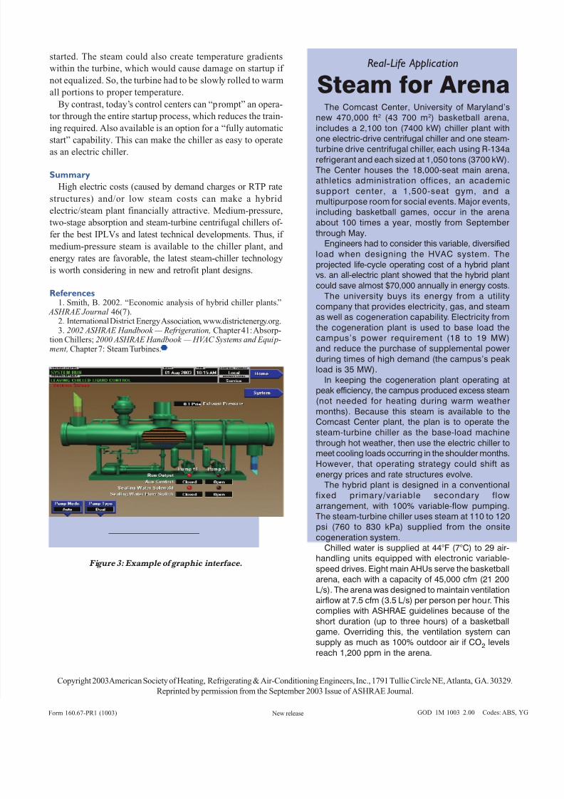
On steam-turbine centrifugal chillers, the introduction of
microprocessor controls allows all the system components to
operate together in the most efficient manner — a task thatwas not possible with older control technologies. Tradition-
ally, an amalgam of various component controls had been ap-
plied to steam-turbine chillers. More integration of components
results in more integration of controls. Although new, micro-
processor-based, graphical control centers present more data,
they are more intuitive and simpler to use ( Figure 3).
Perhaps the area where microprocessor controls have had
the biggest impact on steam-turbine centrifugal chillers is in
the area of chiller startup. With older style chillers, operators
had to be specially trained for the manual startup process. Hot
steam entering a cool turbine resulted in some condensed
water, which had to be drained before the turbine could be
90
80
70
60
50
E C W T ( ° F )
0 20 40 60 80 100% Load
Two-Stage AbsorptionSteam-Turbine Centrifugal
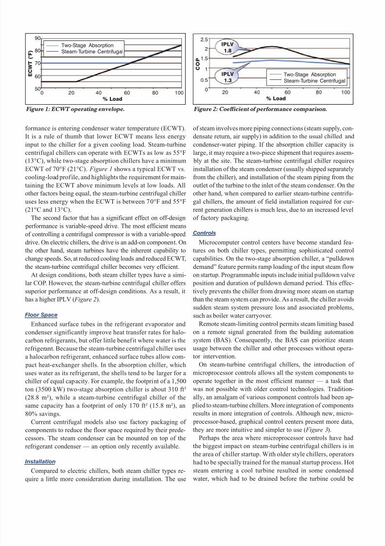
Figure 1: ECWT operating envelope. Figure 2: Coefficient of performance comparison.
IPLV
1.8
IPLV 1.3
20 40 60 80 100% Load
2.5
2
1.5
1
0.5
0
C O P
Two-Stage AbsorptionSteam-Turbine Centrifugal
formance is entering condenser water temperature (ECWT).
It is a rule of thumb that lower ECWT means less energy
input to the chiller for a given cooling load. Steam-turbine
centrifugal chillers can operate with ECWTs as low as 55°F
(13°C), while two-stage absorption chillers have a minimum
ECWT of 70°F (21°C). Figure 1 shows a typical ECWT vs.
cooling-load profile, and highlights the requirement for main-
taining the ECWT above minimum levels at low loads. All
other factors being equal, the steam-turbine centrifugal chiller
uses less energy when the ECWT is between 70°F and 55°F
(21°C and 13°C).
The second factor that has a significant effect on off-design
performance is variable-speed drive. The most efficient means
of controlling a centrifugal compressor is with a variable-speed
drive. On electric chillers, the drive is an add-on component. On
the other hand, steam turbines have the inherent capability to
change speeds. So, at reduced cooling loads and reduced ECWT,
the steam-turbine centrifugal chiller becomes very efficient.
At design conditions, both steam chiller types have a simi-
lar COP. However, the steam-turbine centrifugal chiller offers
superior performance at off-design conditions. As a result, it
has a higher IPLV ( Figure 2).
Floor Space
Enhanced surface tubes in the refrigerant evaporator and
condenser significantly improve heat transfer rates for halo-
carbon refrigerants, but offer little benefit where water is the
refrigerant. Because the steam-turbine centrifugal chiller uses
a halocarbon refrigerant, enhanced surface tubes allow com-
pact heat-exchanger shells. In the absorption chiller, which
uses water as its refrigerant, the shells tend to be larger for a
chiller of equal capacity. For example, the footprint of a 1,500ton (3500 kW) two-stage absorption chiller is about 310 ft²
(28.8 m²), while a steam-turbine centrifugal chiller of the
same capacity has a footprint of only 170 ft² (15.8 m²), an
80% savings.
Current centrifugal models also use factory packaging of
components to reduce the floor space required by their prede-
cessors. The steam condenser can be mounted on top of the
refrigerant condenser — an option only recently available.
Installation
Compared to electric chillers, both steam chiller types re-
quire a little more consideration during installation. The use
8/3/2019 160.67-PR1 - Advances in Steam Cooling ASHRAE
http://slidepdf.com/reader/full/16067-pr1-advances-in-steam-cooling-ashrae 4/4
started. The steam could also create temperature gradients
within the turbine, which would cause damage on startup if
not equalized. So, the turbine had to be slowly rolled to warm
all portions to proper temperature.
By contrast, today’s control centers can “prompt” an opera-
tor through the entire startup process, which reduces the train-
ing required. Also available is an option for a “fully automatic
start” capability. This can make the chiller as easy to operateas an electric chiller.
Summary
High electric costs (caused by demand charges or RTP rate
structures) and/or low steam costs can make a hybrid
electric/steam plant financially attractive. Medium-pressure,
two-stage absorption and steam-turbine centrifugal chillers of-
fer the best IPLVs and latest technical developments. Thus, if
medium-pressure steam is available to the chiller plant, and
energy rates are favorable, the latest steam-chiller technology
is worth considering in new and retrofit plant designs.
References1. Smith, B. 2002. “Economic analysis of hybrid chiller plants.”
ASHRAE Journal 46(7).2. International District Energy Association, www.districtenergy.org.3. 2002 ASHRAE Handbook — Refrigeration, Chapter 41: Absorp-
tion Chillers; 2000 ASHRAE Handbook — HVAC Systems and Equip-ment, Chapter 7: Steam Turbines.
The Comcast Center, University of Maryland’snew 470,000 ft2 (43 700 m2) basketball arena,
includes a 2,100 ton (7400 kW) chiller plant with
one electric-drive centrifugal chiller and one steam-turbine drive centrifugal chiller, each using R-134a
refrigerant and each sized at 1,050 tons (3700 kW).The Center houses the 18,000-seat main arena,athletics administration offices, an academic
support center, a 1,500-seat gym, and amultipurpose room for social events. Major events,including basketball games, occur in the arena
about 100 times a year, mostly from September
through May.Engineers had to consider this variable, diversified
load when designing the HVAC system. The
projected life-cycle operating cost of a hybrid plantvs. an all-electric plant showed that the hybrid plant
could save almost $70,000 annually in energy costs.
The university buys its energy from a utilitycompany that provides electricity, gas, and steamas well as cogeneration capability. Electricity from
the cogeneration plant is used to base load thecampus’s power requirement (18 to 19 MW)and reduce the purchase of supplemental power
during times of high demand (the campus’s peakload is 35 MW).
In keeping the cogeneration plant operating atpeak efficiency, the campus produced excess steam
(not needed for heating during warm weather
months). Because this steam is available to the
Comcast Center plant, the plan is to operate thesteam-turbine chiller as the base-load machine
through hot weather, then use the electric chiller tomeet cooling loads occurring in the shoulder months.
However, that operating strategy could shift as
energy prices and rate structures evolve.The hybrid plant is designed in a conventional
fixed primary/variable secondary flow
arrangement, with 100% variable-flow pumping.The steam-turbine chiller uses steam at 110 to 120psi (760 to 830 kPa) supplied from the onsite
cogeneration system.Chilled water is supplied at 44°F (7°C) to 29 air-
handling units equipped with electronic variable-speed drives. Eight main AHUs serve the basketballarena, each with a capacity of 45,000 cfm (21 200
L/s). The arena was designed to maintain ventilationairflow at 7.5 cfm (3.5 L/s) per person per hour. Thiscomplies with ASHRAE guidelines because of the
short duration (up to three hours) of a basketballgame. Overriding this, the ventilation system cansupply as much as 100% outdoor air if CO2 levels
reach 1,200 ppm in the arena.
Real-Life Application
Copyright 2003American Society of Heating, Refrigerating & Air-Conditioning Engineers, Inc., 1791 Tullie Circle NE, Atlanta, GA. 30329.
Reprinted by permission from the September 2003 Issue of ASHRAE Journal.
Form 160.67-PR1 (1003) GOD 1M 1003 2.00 Codes: ABS, YG New release
Steam for Arena
Figure 3: Example of graphic interface.