Embed Size (px)
Citation preview
PRODUCT CATALOGUE
HYDRAULIC DOWNHOLE MOTORS

HYDRAULIC DOWNHOLE MOTORS
About company
JSC «NGT» is one of the leading engineering companies in the development of hydraulic downhole motors (HDM) and equipment for multi-level hydrocarbonate recovery in one oil well. The company provides complete production cycle of HDM and single string selective production equipment:
[ Design;
[ Production of prototypes;
[ Stand and field tests;
[ Continuous improvement of design;
[ Commercial production of HDM and equipment for single string selective production.
Main directions of the company's activity:
[ Positive Displacement Motors (PDM's);
[ Bearing sections for PDM's and turbodrills;
[ Turbodrills;
[ Components for PDM's and turbodrills;
[ Bypass valves;
[ Centralizers;
[ Single string selective production equipment;
[ Complete service.
The company has all necessary certificates of conformance and declarations of conformity of technical regulations for designing, producing and exploiting drilling equipment on the territory of Eurasian Union: Certificate of conformance C-RU.ÀÃ35.B.00018 number 0962920 «Hydraulic downhole motors». Certificate of conformance C-RU.ÀÃ35.B.00020 number 0962922 «Adjustable downhole assemblies»
Declaration of conformity of technical regulations of the Customs Union 010/2011 “On safety of machinery and equipment”, number TC N RU Ä-RU.MM04.B.06687
1
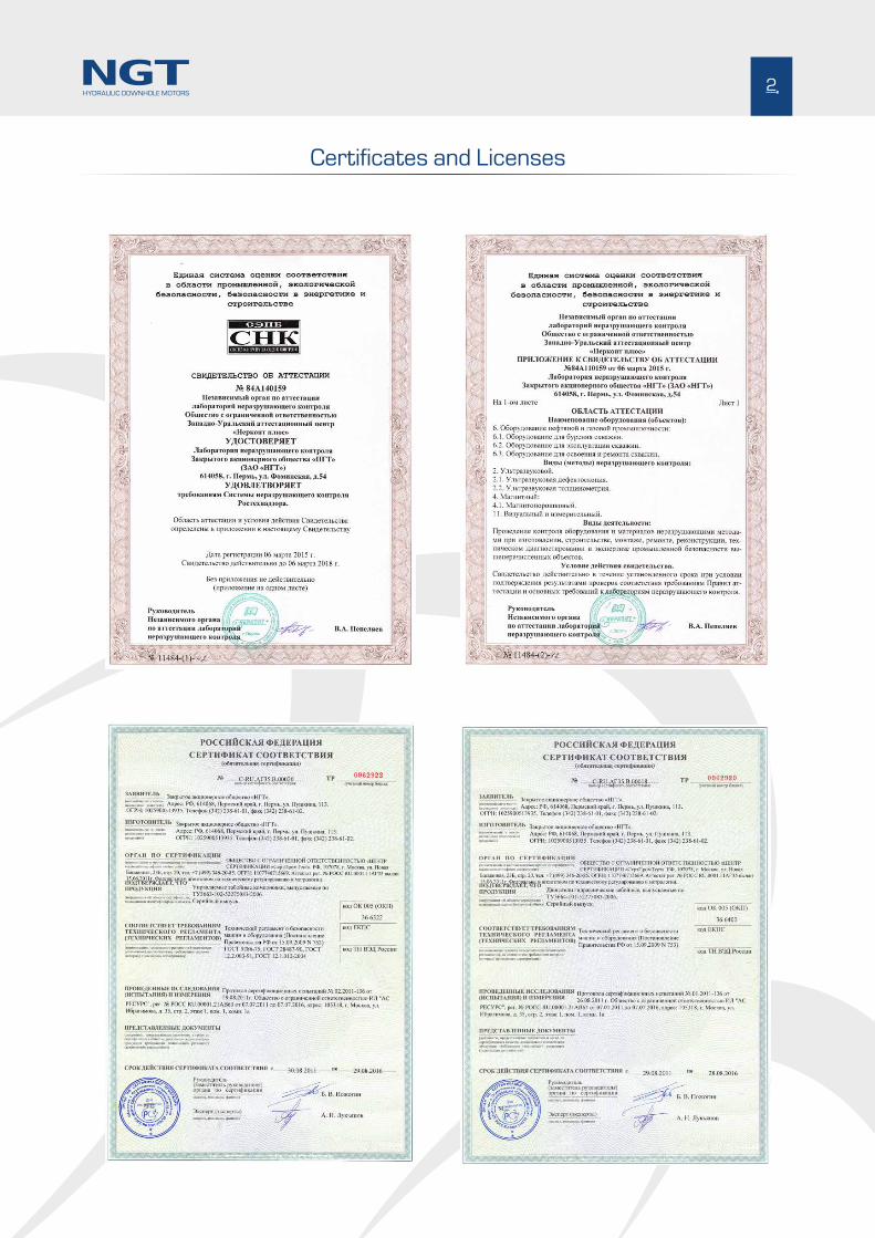
Certificates and Licenses
2HYDRAULIC DOWNHOLE MOTORS

Positive Displacement Motors (PDM's)
3HYDRAULIC DOWNHOLE MOTORS
In the early 60's the idea of creation of PDM based on multilobe screw gerotor mechanism was first born at the Perm Branch of VNIIBT. In 1966 the idea was patented. Further work was provided in cooperation with VNIIBT. The Perm Branch of VNIIBT produced the first 42 mm dia. PDM model, followed by 172 mm dia. prototype of 9/10 power section lobe configuration which was successfully field tested. Later, all standard size PDM's within the range of 42-240 mm were developed and produced.
The new Russian design was recognized worldover.
In the early 1980's the production licenses were sold to Drilex company. In the early 1990's the term of the licenses sold expired and currently there are more than 30 companies dealing with the production of PDM multilobe power sections all over the world.
Since then, during 47 years PDM's have passed evolutionary trend of development becoming one of the most efficient tools for well drilling.
High torque PDC bits featuring enhanced operation life have set up new demands to the power section characteristics. Recently the leading manufacturers have managed to increase significantly the torque and life due to increase of the power section length. The power section life at that time highly exceeded PDM spindle overhaul life.
Our company has developed high capacity reliable spindles featuring enhanced life and the longest overhaul period of PDM's among Russian producers.
The special attention of the company is paid to trouble-free run of PDM's produced. Each motor is equipped with two emergency devices:
- the emergency device on the spindle shaft, which in case of the shaft break (in its thin section) will not allow the shaft to drop out from the spindle housing;
- the top sub (safety sub) has the fishing tool to pull out PDM parts using the rotor in case of breaks or thread unscrewing.
This catalogue presents our most popular PDM's among our customers.
28 PDM's performance in the Kazakhstan Republic
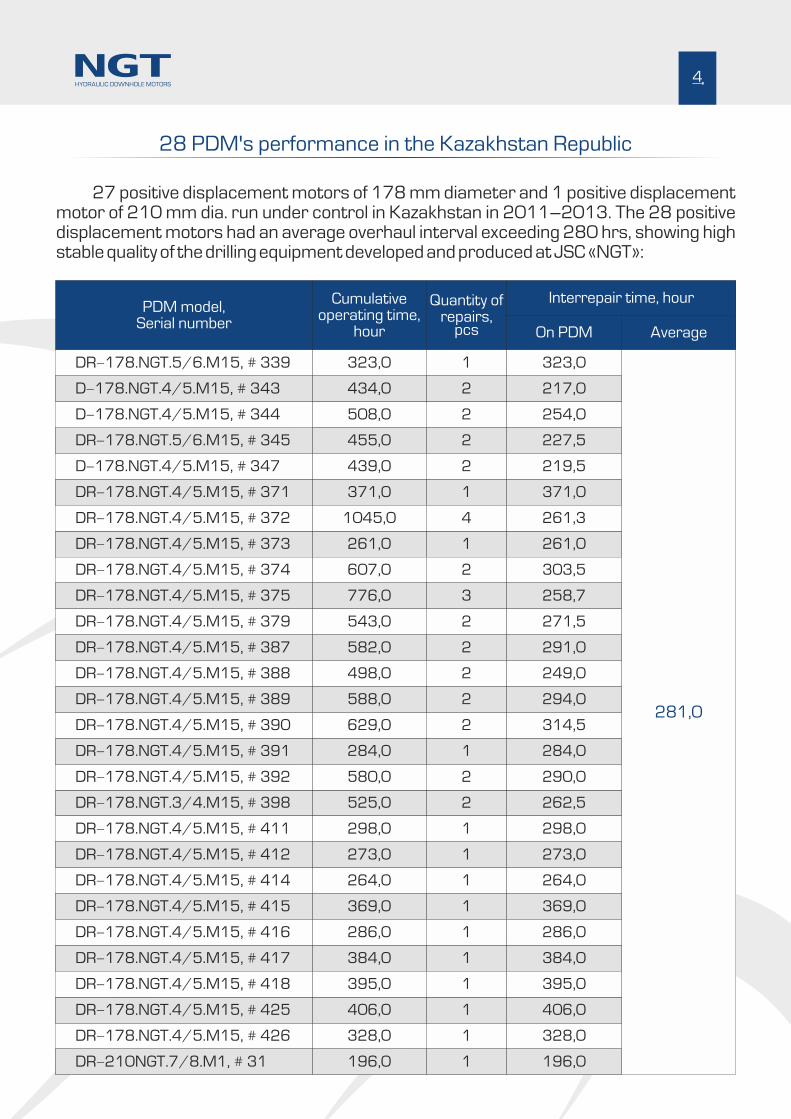
27 positive displacement motors of 178 mm diameter and 1 positive displacement motor of 210 mm dia. run under control in Kazakhstan in 2011–2013. The 28 positive displacement motors had an average overhaul interval exceeding 280 hrs, showing high stable quality of the drilling equipment developed and produced at JSC «NGT»:
Cumulativeoperating time,
hour
Quantity ofrepairs,
pcs On PDM
Interrepair time, hour
Average
323,0
629,0
1
2
323,0
314,5281,0
508,0
580,0
2
2
254,0
290,0
455,0
525,0
2
2
227,5
262,5
439,0
298,0
2
1
219,5
298,0
371,0
273,0
1
1
371,0
273,0
1045,0
264,0
4
1
261,3
264,0
261,0
369,0
1
1
261,0
369,0
607,0
286,0
2
1
303,5
286,0
776,0
384,0
3
1
258,7
384,0
543,0
395,0
328,0
2
1
1
271,5
395,0
328,0
582,0
406,0
196,0
2
1
1
291,0
406,0
196,0
498,0 2 249,0
588,0 2 294,0
434,0
284,0
2
1
217,0
284,0
PDM model,Serial number
DR-178.NGT.4/5.M15, # 390
DR-178.NGT.4/5.M15, # 392
DR-178.NGT.5/6.M15, # 345
DR-178.NGT.3/4.M15, # 398
D-178.NGT.4/5.M15, # 347
DR-178.NGT.4/5.M15, # 411
DR-178.NGT.4/5.M15, # 371
DR-178.NGT.4/5.M15, # 412
DR-178.NGT.4/5.M15, # 372
DR-178.NGT.4/5.M15, # 414
DR-178.NGT.4/5.M15, # 373
DR-178.NGT.4/5.M15, # 415
DR-178.NGT.4/5.M15, # 374
DR-178.NGT.4/5.M15, # 416
DR-178.NGT.4/5.M15, # 375
DR-178.NGT.4/5.M15, # 417
DR-178.NGT.4/5.M15, # 379
DR-178.NGT.4/5.M15, # 418
DR-178.NGT.4/5.M15, # 426
DR-178.NGT.4/5.M15, # 387
DR-178.NGT.4/5.M15, # 425
DR-210NGT.7/8.M1, # 31
DR-178.NGT.4/5.M15, # 388
DR-178.NGT.4/5.M15, # 389
DR-178.NGT.4/5.M15, # 391
DR-178.NGT.5/6.M15, # 339
D-178.NGT.4/5.M15, # 343
D-178.NGT.4/5.M15, # 344
4HYDRAULIC DOWNHOLE MOTORS

JSC «NGT» company offers a wide range of PDM's for drilling to customers. For convenience of the catalogue use, please, see below the PDM designation description:
Positive displacement motor modification number
Length of stator rubber lining, dm
Power section lobe configuration
Standard size, producer designation
Designation of PDM where:
D - positive displacement motor,
DO - downhole motor-whipstock with fixed
bend angle,
DR - downhole motor-whipstock with
adjustable housing
PDM's presented in the catalogue:
D-76.NGT.4/5.20.M1
DO-76.NGT.4/5.20.M1
DR-76.NGT.4/5.20.M2
DR-88.NGT.5/6.20.M1
DR-88.NGT.5/6.24.M1
DR-88.NGT.7/8.27.M1
DR-95.NGT.7/8.44.M1
DR-95.NGT.7/8.53.M1
DR-106.NGT.5/6.53.M1
DR-106.NGT.7/8.30.M1
DR-106.NGT.5/6.53.M2
DR-106.NGT.7/8.30.M2
DR-120.NGT.6/7.30.M2
DR-120.NGT.7/8.59.M2
DR-165.NGT.7/8.58.M1
DR-165.NGT.7/8.69.M1
DR-178.NGT.7/8.52.M15
DR-178.NGT.7/8.55.M15
DR-178.NGT.7/8.62.M15
DR-178.NGT.7/8.63.M15
DR-178.NGT.7/8.64.M15
DR-178.NGT.4/5.54.M23
DR-178.NGT.7/8.52.M23
DR-178.NGT.7/8.55.M23
DR-178.NGT.7/8.62.M23
DR-178.NGT.7/8.63.M23
DR-178.NGT.7/8.64.M23
DR-195.NGT.5/6.43.M1
DR-195.NGT.6/7.43.M1
DR-210.NGT.7/8.42.M1
DR-210.NGT.7/8.50.M1
DR-240.NGT.3/4.62.M1
DR-240.NGT.3/4.63.M1
DR-240.NGT.5/6.63.M1
DR-106.NGT.5/6.53.M1
Designation of Positive Displacement Motors
5HYDRAULIC DOWNHOLE MOTORS
D-76.NGT.4/5.20.M1
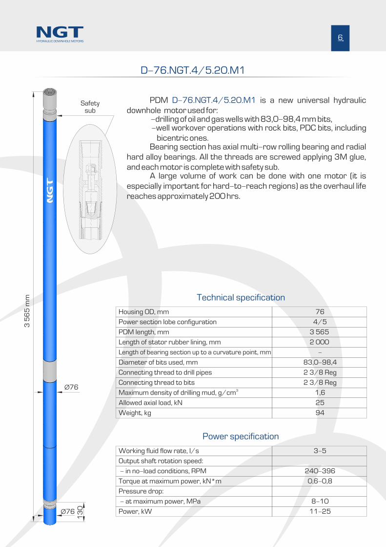
PDM is a new universal hydraulic D-76.NGT.4/5.20.M1
downhole motor used for: -drilling of oil and gas wells with 83,0-98,4 mm bits, -well workover operations with rock bits, PDC bits, including
bicentric ones. Bearing section has axial multi-row rolling bearing and radial
hard alloy bearings. All the threads are screwed applying 3M glue,
and each motor is complete with safety sub. A large volume of work can be done with one motor (it is
especially important for hard-to-reach regions) as the overhaul life
reaches approximately 200 hrs.
Power section lobe configuration
Housing OD, mm
Working fluid flow rate, l/s
Length of bearing section up to a curvature point, mm
Diameter of bits used, mm
Length of stator rubber lining, mm
PDM length, mm
Connecting thread to drill pipes
Output shaft rotation speed:
Connecting thread to bits3Maximum density of drilling mud, g/cm
Allowed axial load, kN
Weight, kg
4/5
76
3-5
-
83,0-98,4
2 000
3 565
2 3/8 Reg
2 3/8 Reg
1,6
25
94
Technical specification
Power specification
Torque at maximum power, kN*m
- in no-load conditions, RPM
Pressure drop:
0,6-0,8
240-396
- at maximum power, MPa 8-10
Power, kW 11-25
6
Ø76
13
0
Ø76
3 5
65
mm
Safetysub
HYDRAULIC DOWNHOLE MOTORS
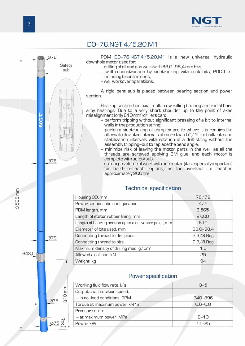
DO-76.NGT.4/5.20.M1
PDM is a new universal hydraulic DO-76.NGT.4/5.20.M1downhole motor used for: -drilling of oil and gas wells with 83,0-98,4 mm bits, - well reconstruction by sidetracking with rock bits, PDC bits,
including bicentric ones; - well workover operations.
A rigid bent sub is placed between bearing section and power section.
Bearing section has axial multi-row rolling bearing and radial hard alloy bearings. Due to a very short shoulder up to the point of axes misalignment (only 810 mm) drillers can: - perform tripping without significant pressing of a bit to internal
walls in the production string; - perform sidetracking of complex profile where it is required to
alternate deviated intervals of more than 5°/10 m built rate and stabilization intervals with rotation of a drill string without the assembly tripping-out to replace the bend angle.
- minimize risk of leaving the motor parts in the well, as all the threads are screwed applying 3M glue, and each motor is complete with safety sub.
- do a large volume of work with one motor (it is especially important for hard-to-reach regions) as the overhaul life reaches approximately 200 hrs.
R43,5
7
Ø76
Ø76
Ø79
Ø76
13
0
Ø76
3 5
65
mm
81
0 m
m
4/5
76/79
3-5
2 3/8 Reg
2 3/8 Reg
1,6
25
94
Technical specification
Power specification
0,6-0,8
240-396
8-10
11-25
810
83,0-98,4
2 000
3 565
HYDRAULIC DOWNHOLE MOTORS
Safetysub
Power section lobe configuration
Housing OD, mm
Working fluid flow rate, l/s
Length of bearing section up to a curvature point, mm
Diameter of bits used, mm
Length of stator rubber lining, mm
PDM length, mm
Connecting thread to drill pipes
Output shaft rotation speed:
Connecting thread to bits3Maximum density of drilling mud, g/cm
Allowed axial load, kN
Weight, kg
Torque at maximum power, kN*m
- in no-load conditions, RPM
Pressure drop:
- at maximum power, MPa
Power, kW

DR-76.NGT.4/5.20.M2
PDM is a new universal hydraulic DR-76.NGT.4/5.20.M2downhole motor used for: - drilling of oil and gas wells with 83,0-98,4 mm bits, - well reconstruction by sidetracking with rock bits, PDC bits,
including bicentric ones; - well workover operations.
An adjustable bent sub is placed between bearing section and power section. The adjustment range is between 0° and 2°or between 0° and 3°.
Bearing section has axial multi-row rolling bearing and radial hard alloy bearings. Due to a very short shoulder up to the point of axes misalignment (only 855 mm) drillers can: - perform tripping without significant pressing of a bit to internal
walls in the production string; - perform sidetracking of complex profile where it is required to
alternate deviated intervals of more than 5°/10 m built rate and stabilization intervals with rotation of a drill string without the assembly tripping-out to replace the bend angle;
- minimize risk of leaving the motor parts in the well, as all the threads are screwed applying 3M glue, and each motor is complete with safety sub;
- do a large volume of work with one motor (it is especially important for hard-to-reach regions) as the overhaul life reaches approximately 200 hrs.
8
R43,5
Ø76
Ø76
Ø80
Ø80
13
0
Ø76
3 6
46
mm
85
5 m
m
0°-2°0°-3°
4/5
76/80
3-5
2 3/8 Reg
2 3/8 Reg
1,6
45
97
Technical specification
Power specification
0,6-0,8
240-396
8-10
11-25
855
83,0-98,4
2 000
3 646
HYDRAULIC DOWNHOLE MOTORS
Power section lobe configuration
Housing OD, mm
Working fluid flow rate, l/s
Length of bearing section up to a curvature point, mm
Diameter of bits used, mm
Length of stator rubber lining, mm
PDM length, mm
Connecting thread to drill pipes
Output shaft rotation speed:
Connecting thread to bits3Maximum density of drilling mud, g/cm
Allowed axial load, kN
Weight, kg
Torque at maximum power, kN*m
- in no-load conditions, RPM
Pressure drop:
- at maximum power, MPa
Power, kW
Safetysub
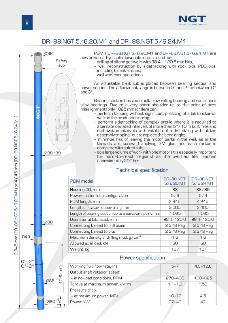
DR-88.NGT.5/6.20.M1 DR-88.NGT.5/6.24.M1and
PDM’s and are DR-88.NGT.5/6.20.M1 DR-88.NGT.5/6.24.M1new universal hydraulic downhole motors used for: - drilling of oil and gas wells with 98.4 – 120.6 mm bits, - well reconstruction by sidetracking with rock bits, PDC bits,
including bicentric ones; - well workover operations.
An adjustable bent sub is placed between bearing section and power section. The adjustment range is between 0° and 2°or between 0° and 3°.
Bearing section has axial multi-row rolling bearing and radial hard alloy bearings. Due to a very short shoulder up to the point of axes misalignment (only 1025 mm) drillers can: - perform tripping without significant pressing of a bit to internal
walls in the production string; - perform sidetracking of complex profile where it is required to
alternate deviated intervals of more than 5°/10 m built rate and stabilization intervals with rotation of a drill string without the assembly tripping-out to replace the bend angle;
- minimize risk of leaving the motor parts in the well, as all the threads are screwed applying 3M glue, and each motor is complete with safety sub;
- do a large volume of work with one motor (it is especially important for hard-to-reach regions) as the overhaul life reaches approximately 200 hrs.
9
R49
Ø88
Ø88/89
Ø88
Ø88
15
4
Ø80
3 8
45
mm
()
or
4 2
45
mm
()
DR
-8
8.N
GT
.5/
6.2
0.M
1
DR
-8
8.N
GT
.5/
6.2
4.M
1
10
25
mm
0°-2°0°-3°
Power section lobe configuration
Housing OD, mm
PDM model
Working fluid flow rate, l/s
Length of bearing section up to a curvature point, mm
Diameter of bits used, mm
Length of stator rubber lining, mm
PDM length, mm
Connecting thread to drill pipes
Output shaft rotation speed:
Connecting thread to bits3Maximum density of drilling mud, g/cm
Allowed axial load, kN
Weight, kg
5/6 5/6
88
DR-88.NGT.5/6.20.M1
88/89
DR-88.NGT.5/6.24.M1
5-7 4,3-12,8
1 025 1 025
98,4-120,6 98,4-120,6
2 000 2 400
3 845 4 245
2 3/8 Reg 2 3/8 Reg
2 3/8 Reg 2 3/8 Reg
1,6 1,6
50 50
137 151
Technical specification
Power specification
Torque at maximum power, kN*m
- in no-load conditions, RPM
Pressure drop:
1,1-1,3 1,53
270-400 108-325
- at maximum power, MPa 10-13 4,5
Power, kW 27-43 47
HYDRAULIC DOWNHOLE MOTORS
Safetysub

DR-88.NGT.7/8.27.M1
PDM is a new universal hydraulic DR-88.NGT.7/8.27.M1downhole motor used for:
- drilling of oil and gas wells with 98.4 – 120.6 mm bits,- well reconstruction by sidetracking with rock bits, PDC bits,
including bicentric ones;- well workover operations.
An adjustable bent sub is placed between bearing section and power section. The adjustment range is between 0° and 2°or between 0° and 3°.
Bearing section has axial multi-row rolling bearing and radial hard alloy bearings. Due to a very short shoulder up to the point of axes misalignment (only 1025 mm) drillers can:
- perform tripping without significant pressing of a bit to internal walls in the production string;
- perform sidetracking of complex profile where it is required to alternate deviated intervals of more than 5°/10 m built rate and stabilization intervals with rotation of a drill string without the assembly tripping-out to replace the bend angle.
- minimize risk of leaving the motor parts in the well, as all the threads are screwed applying 3M glue, and each motor is complete with safety sub.
- do a large volume of work with one motor (it is especially important for hard-to-reach regions) as the overhaul life reaches approximately 200 hrs.
R49
Ø88
Ø89
Ø88
Ø88
15
4
Ø80
4 5
81
mm
10
25
mm
0°-2°0°-3°
7/8
88/89
2,8-8,2
2 3/8 Reg
2 3/8 Reg
1,6
50
162
1,34
74-215
4,3
28
1 025
98,4-120,6
2 736
4 581
10HYDRAULIC DOWNHOLE MOTORS
Power section lobe configuration
Housing OD, mm
Working fluid flow rate, l/s
Length of bearing section up to a curvature point, mm
Diameter of bits used, mm
Length of stator rubber lining, mm
PDM length, mm
Connecting thread to drill pipes
Output shaft rotation speed:
Connecting thread to bits3Maximum density of drilling mud, g/cm
Allowed axial load, kN
Weight, kg
Torque at maximum power, kN*m
- in no-load conditions, RPM
Pressure drop:
- at maximum power, MPa
Power, kW
Technical specification
Power specification
Safetysub
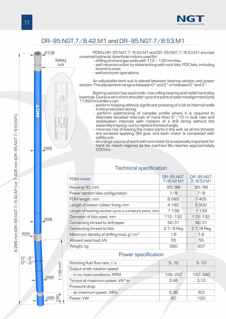
DR-95.NGT.7/8.42.M1 DR-95.NGT.7/8.53.M1 and
PDM’s and are new DR-95.NGT.7/8.42.M1 DR-95.NGT.7/8.53.M1universal hydraulic downhole motors used for: - drilling of oil and gas wells with 112 – 132 mm bits, - well reconstruction by sidetracking with rock bits, PDC bits, including
bicentric ones; - well workover operations.
An adjustable bent sub is placed between bearing section and power section. The adjustment range is between 0° and 2° or between 0° and 3°. Bearing section has axial multi-row rolling bearing and radial hard alloy bearings. Due to a very short shoulder up to the point of axes misalignment (only 1139 mm) drillers can: - perform tripping without significant pressing of a bit to internal walls
in the production string; - perform sidetracking of complex profile where it is required to
alternate deviated intervals of more than 5°/10 m built rate and stabilization intervals with rotation of a drill string without the assembly tripping-out to replace the bend angle.
- minimize risk of leaving the motor parts in the well, as all the threads are screwed applying 3M glue, and each motor is completed with safety sub.
- do a large volume of work with one motor (it is especially important for hard-to-reach regions) as the overhaul life reaches approximately 200 hrs.
R59
Ø106
Ø95
Ø98
Ø98
15
0
Ø95
1 1
39
mm
0°-2°0°-3°
7/8 7/8
95/98
DR-95.NGT.7/8.42.M1
95/98
DR-95.NGT.7/8.53.M1
5-10 5-10
NC 31 NC 31
2 7/8 Reg 2 7/8 Reg
1,6 1,6
55 55
260 307
Technical specification
Power specification
2,46 3,12
126-257 150-340
5,36 8,0
60 100
6 2
85
mm
o
r 7
40
5 m
m
)(
)(
DR
-9
5.N
GT
.7/
8.4
2.M
1
DR
-9
5.N
GT
.7/
8.5
3.M
1
1 139 1 139
112-132 112-132
4 180 5 300
6 285 7 405
11HYDRAULIC DOWNHOLE MOTORS
Safetysub
Power section lobe configuration
Housing OD, mm
PDM model
Working fluid flow rate, l/s
Length of bearing section up to a curvature point, mm
Diameter of bits used, mm
Length of stator rubber lining, mm
PDM length, mm
Connecting thread to drill pipes
Output shaft rotation speed:
Connecting thread to bits3Maximum density of drilling mud, g/cm
Allowed axial load, kN
Weight, kg
Torque at maximum power, kN*m
- in no-load conditions, RPM
Pressure drop:
- at maximum power, MPa
Power, kW

DR M DR M-106.NGT.5/6.53. 1 -106.NGT.7/8.30. 1 and
PDM’s and are DR-106.NGT.5/6.53.M1 DR-106.NGT.7/8.30.M1new universal hydraulic downhole motors used for: - drilling of oil and gas wells with 120.6 – 149.2 mm bits, - well reconstruction by sidetracking with rock bits, PDC bits, including
bicentric ones; - well workover operations.
An adjustable bent sub is placed between bearing section and power section. The adjustment range is between 0° and 2° or between 0° and 3°. PDMs are completed with the bearing section of enhanced operational life, exceeding 300 hrs.
The bearing section is fitted with the axial sliding bearing, having operating surfaces made of synthetic diamond, and the radial hard alloy bearings. Due to a very short shoulder up to the point of axes misalignment (only 883 mm) drillers can: - perform tripping without significant pressing of a bit to internal walls
in the production string; - perform sidetracking of complex profile where it is required to
alternate deviated intervals of more than 5°/10 m built rate and stabilization intervals with rotation of a drill string without the assembly tripping-out to replace the bend angle;
- minimize risk of leaving the motor parts in the well, as all the threads are screwed applying Loctite glue, and each motor is completed with safety sub;
- do a large volume of work with one motor (it is especially important for hard-to-reach regions) as the overhaul life reaches approximately 300 hrs.
R59
Ø106
Ø106
Ø110
Ø106
18
0
Ø100
7 1
54
mm
()
or
4 8
54
mm
()
DR
DR
M-
10
6.N
GT
.5/
6.5
3.Ì
1-
10
6.N
GT
.7/
8.3
0.
1
88
3 m
m
0°-2°0°-3°
5/6 7/8
105/110
DR-106.NGT.5/6.53.M1
106/110
DR-106.NGT.7/8.30.M1
6-12 6-12
NC 31 NC 31
2 7/8 Reg 2 7/8 Reg
1,6 1,6
80 80
369 250
3,25 2,3-3,5
161-321 96-192
8 5-10
99 53
883 883
120,6-149,2 120,6-149,2
5 320 3 000
7 154 4 854
12HYDRAULIC DOWNHOLE MOTORS
Power section lobe configuration
Housing OD, mm
PDM model
Working fluid flow rate, l/s
Length of bearing section up to a curvature point, mm
Diameter of bits used, mm
Length of stator rubber lining, mm
PDM length, mm
Connecting thread to drill pipes
Output shaft rotation speed:
Connecting thread to bits3Maximum density of drilling mud, g/cm
Allowed axial load, kN
Weight, kg
Torque at maximum power, kN*m
- in no-load conditions, RPM
Pressure drop:
- at maximum power, MPa
Power, kW
Technical specification
Power specification
Safetysub
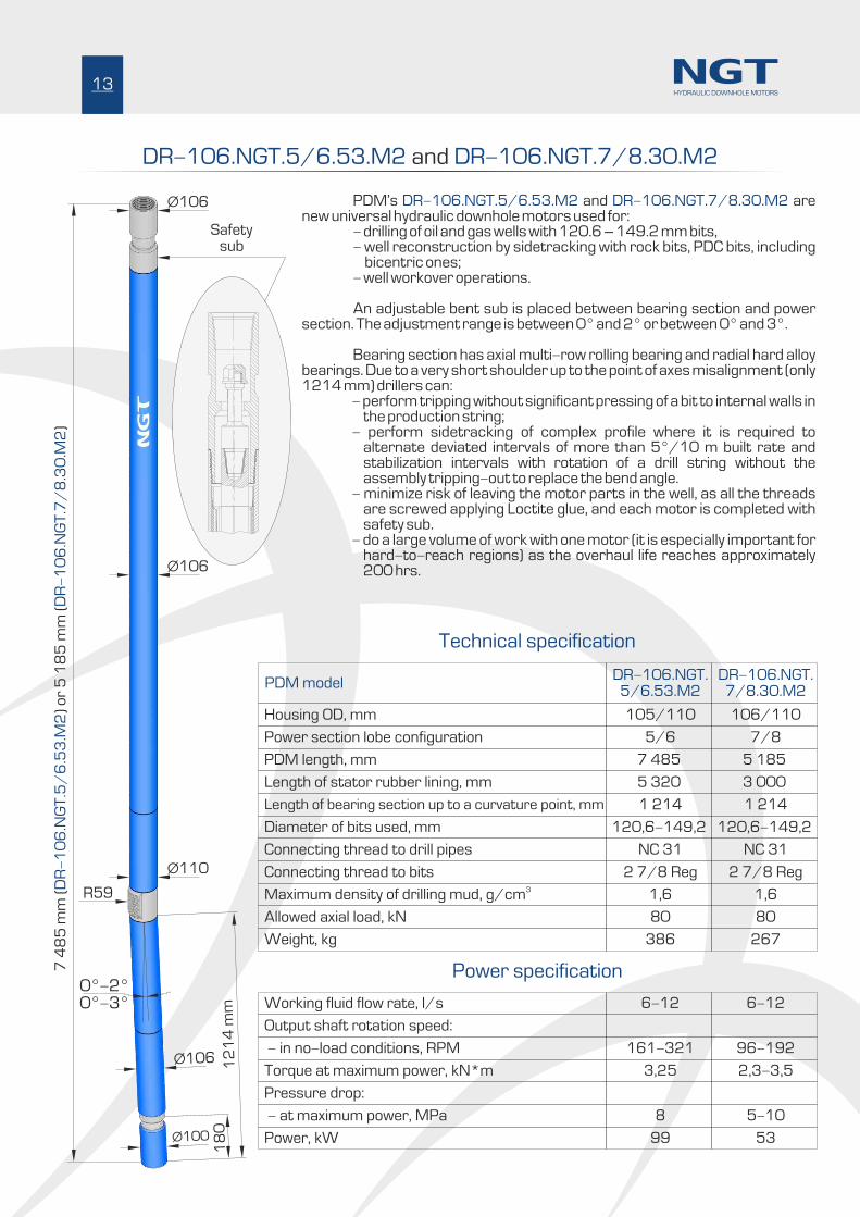
DR M2 DR M-106.NGT.5/6.53. -106.NGT.7/8.30. 2 and
PDM’s and are DR-106.NGT.5/6.53.M2 DR-106.NGT.7/8.30.M2new universal hydraulic downhole motors used for: - drilling of oil and gas wells with 120.6 – 149.2 mm bits, - well reconstruction by sidetracking with rock bits, PDC bits, including
bicentric ones; - well workover operations.
An adjustable bent sub is placed between bearing section and power section. The adjustment range is between 0° and 2° or between 0° and 3°.
Bearing section has axial multi-row rolling bearing and radial hard alloy bearings. Due to a very short shoulder up to the point of axes misalignment (only 1214 mm) drillers can:
- perform tripping without significant pressing of a bit to internal walls in the production string;
- perform sidetracking of complex profile where it is required to alternate deviated intervals of more than 5°/10 m built rate and stabilization intervals with rotation of a drill string without the assembly tripping-out to replace the bend angle.
- minimize risk of leaving the motor parts in the well, as all the threads are screwed applying Loctite glue, and each motor is completed with safety sub.
- do a large volume of work with one motor (it is especially important for hard-to-reach regions) as the overhaul life reaches approximately 200 hrs.
R59
Ø106
Ø106
Ø106
18
0
Ø100
12
14
mm
0°-2°0°-3°
5/6 7/8
105/110
DR-106.NGT.5/6.53.M2
106/110
DR-106.NGT.7/8.30.M2
6-12 6-12
NC 31 NC 31
2 7/8 Reg 2 7/8 Reg
1,6 1,6
80 80
386 267
3,25 2,3-3,5
161-321 96-192
8 5-10
99 53
7 4
85
mm
()
or
5 1
85
mm
()
DR
M2
DR
M2
-1
06
.NG
T.5
/6
.53
.-
10
6.N
GT
.7/
8.3
0.
Ø110
1 214 1 214
120,6-149,2 120,6-149,2
5 320 3 000
7 485 5 185
13HYDRAULIC DOWNHOLE MOTORS
Power section lobe configuration
Housing OD, mm
PDM model
Working fluid flow rate, l/s
Length of bearing section up to a curvature point, mm
Diameter of bits used, mm
Length of stator rubber lining, mm
PDM length, mm
Connecting thread to drill pipes
Output shaft rotation speed:
Connecting thread to bits3Maximum density of drilling mud, g/cm
Allowed axial load, kN
Weight, kg
Torque at maximum power, kN*m
- in no-load conditions, RPM
Pressure drop:
- at maximum power, MPa
Power, kW
Technical specification
Power specification
Safetysub

DR-120.NGT.6/7.30.M2 DR-120.NGT.7/8.59.M2 and
PDM’s and are DR-120.NGT.6/7.30.M2 DR-120.NGT.7/8.59.M2new universal hydraulic downhole motors used for: - drilling of oil and gas wells with 139.7 – 165.1 mm bits, - well reconstruction by sidetracking with rock bits, PDC bits, including
bicentric ones; - well workover operations.
An adjustable bent sub is placed between bearing section and power section. The adjustment range is between 0° and 2° or between 0° and 3°.
Bearing section has axial multi-row rolling bearing and radial hard alloy bearings. Due to a very short shoulder up to the point of axes misalignment (only 1370 mm) drillers can: - perform tripping without significant pressing of a bit to internal walls
in the production string; - perform sidetracking of complex profile where it is required to
alternate deviated intervals of more than 5°/10 m built rate and stabilization intervals with rotation of a drill string without the assembly tripping-out to replace the bend angle.
- minimize risk of leaving the motor parts in the well, as all the threads are screwed applying Loctite glue, and each motor is completed with safety sub.
- do a large volume of work with one motor (it is especially important for hard-to-reach regions) as the overhaul life reaches approximately 200 hrs.
R59
Ø120
Ø120
Ø120
Ø120
18
0
Ø115
13
70
mm
0°-2°0°-3°
5 4
07
mm
()
or
8 2
37
mm
()
DR
M2
DR
M2
-1
20
.NG
T.6
/7
.30
.-
12
0.N
GT
.7/
8.5
9.
6/7 7/8
120
DR-120.NGT.6/7.30.M2
120
DR-120.NGT.7/8.59.M2
10-20 12-25
NC 38 NC 38
3 1/2 Reg 3 1/2 Reg
1,6 1,6
100 100
358 545
4,7 5,3
162-324 130-261
9,0-13,5 5,2-7,3
101 122
1 370 1 370
139,7-165,1 139,7-165,1
3 000 5 900
5 407 8 237
14HYDRAULIC DOWNHOLE MOTORS
Power section lobe configuration
Housing OD, mm
PDM model
Working fluid flow rate, l/s
Length of bearing section up to a curvature point, mm
Diameter of bits used, mm
Length of stator rubber lining, mm
PDM length, mm
Connecting thread to drill pipes
Output shaft rotation speed:
Connecting thread to bits3Maximum density of drilling mud, g/cm
Allowed axial load, kN
Weight, kg
Torque at maximum power, kN*m
- in no-load conditions, RPM
Pressure drop:
- at maximum power, MPa
Power, kW
Technical specification
Power specification
Safetysub
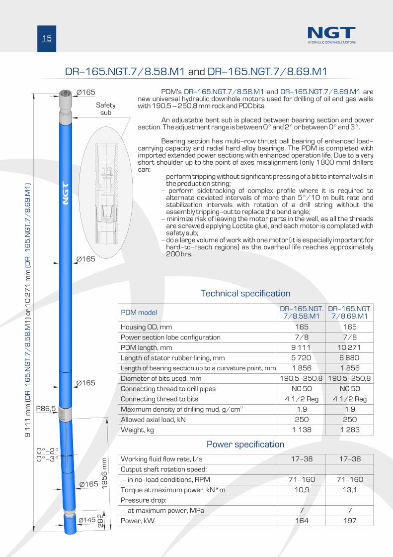
DR-165.NGT.7/8.58.M1 DR-165.NGT.7/8.69.M1 and
PDM’s and are DR-165.NGT.7/8.58.M1 DR-165.NGT.7/8.69.M1new universal hydraulic downhole motors used for drilling of oil and gas wells with 190,5 – 250,8 mm rock and PDC bits.
An adjustable bent sub is placed between bearing section and power section. The adjustment range is between 0° and 2° or between 0° and 3°. Bearing section has multi-row thrust ball bearing of enhanced load-carrying capacity and radial hard alloy bearings. The PDM is completed with imported extended power sections with enhanced operation life. Due to a very short shoulder up to the point of axes misalignment (only 1800 mm) drillers can: - perform tripping without significant pressing of a bit to internal walls in
the production string; - perform sidetracking of complex profile where it is required to
alternate deviated intervals of more than 5°/10 m built rate and stabilization intervals with rotation of a drill string without the assembly tripping-out to replace the bend angle;
- minimize risk of leaving the motor parts in the well, as all the threads are screwed applying Loctite glue, and each motor is completed with safety sub;
- do a large volume of work with one motor (it is especially important for hard-to-reach regions) as the overhaul life reaches approximately 200 hrs.
R86,5
Ø165
Ø165
Ø165
Ø165
28
2
Ø145
18
56
mm
0°-2°0°-3°
7/8 7/8
165
DR-165.NGT.7/8.58.M1
165
DR-165.NGT.7/8.69.M1
17-38 17-38
NC 50 NC 50
4 1/2 Reg 4 1/2 Reg
1,9 1,9
250 250
1 138 1 283
10,9 13,1
71-160 71-160
7 7
164 197
9 1
11
mm
()
or
10
27
1 m
m (
)D
RM
1D
R1
-1
65
.NG
T.7
/8
.58
.-
16
5.N
GT
.7/
8.6
9.Ì
1 856 1 856
190,5-250,8 190,5-250,8
5 720 6 880
9 111 10 271
15HYDRAULIC DOWNHOLE MOTORS
Power section lobe configuration
Housing OD, mm
PDM model
Working fluid flow rate, l/s
Length of bearing section up to a curvature point, mm
Diameter of bits used, mm
Length of stator rubber lining, mm
PDM length, mm
Connecting thread to drill pipes
Output shaft rotation speed:
Connecting thread to bits3Maximum density of drilling mud, g/cm
Allowed axial load, kN
Weight, kg
Torque at maximum power, kN*m
- in no-load conditions, RPM
Pressure drop:
- at maximum power, MPa
Power, kW
Technical specification
Power specification
Safetysub

16
DR-178.NGT.4/5.54.M15 DR-178.NGT.7/8.52.M15 and
PDM’s and DR-178.NGT.4/5.54.M15 DR-178.NGT.7/8.52.M15are new universal hydraulic downhole motors used for drilling of oil and gas wells with rock and PDC bits of 212.7 - 250.8 mm diameter. An adjustable bent sub is placed between bearing section and power section. The adjustment range is between 0° and 2° or between 0° and 3°. The bearing section has multi-row thrust ball bearing of enhanced load-carrying capacity and radial hard alloy bearings. PDMs are completed with imported extended power sections with enhanced operation life. Due to very short shoulder up to the point of axes misalignment (only 1856 mm) drillers can:
- perform tripping without significant pressing of a bit to internal walls in the production string;
- perform sidetracking of complex profile where it is required to alternate deviated intervals of more than 5°/10 m built rate and stabilization intervals with rotation of a drill string without the assembly tripping-out to replace the bend angle.
- minimize risk of leaving the motor parts in the well, as all the threads are screwed applying Loctite glue, and each motor is completed with safety sub.
- do a large volume of work with one motor (it is especially important for hard-to-reach regions) as the overhaul life reaches approximately 280 hrs.
PDMs can be completed with replaceable centralizer and calibrator sub:
Ø195
30
0
Ø145
18
56
mm
0°-2°0°-3°
Ø178
Ø178
Power section lobe configuration
Housing OD, mm
PDM model
Working fluid flow rate, l/s
Length of bearing section up to a curvature point, mm
Diameter of bits used, mm
Length of stator rubber lining, mm
PDM length, mm
Connecting thread to drill pipes
Output shaft rotation speed:
Connecting thread to bits3Maximum density of drilling mud, g/cm
Allowed axial load, kN
Weight, kg
4/5 7/8
178/195
DR-178.NGT.4/5.54.M15
178/195
DR-178.NGT.7/8.52.M15
30 25-40
1 856 1 856
212,7-250,8 212,7-250,8
5 400 5 210
8 751 8 511
NC 50/5 1/2 FH NC 50/5 1/2 FH
4 1/2 Reg 4 1/2 Reg
1,9 1,9
250 250
1 273 1 239
Power specification
Torque at maximum power, kN*m
- in no-load conditions, RPM
Pressure drop:
10 13,4
248 100-160
- at maximum power, MPa 13 13
Power, kW 230 164
Technical specification
8 7
51
mm
()
or
8 5
11
mm
()
DR
45
4M
15
DR
5M
15
-1
78
.NG
T.
/.5
.-
17
8.N
GT
.7/
8.
2.
17
0
Calibrator sub Centralizer
HYDRAULIC DOWNHOLE MOTORS
Safetysub
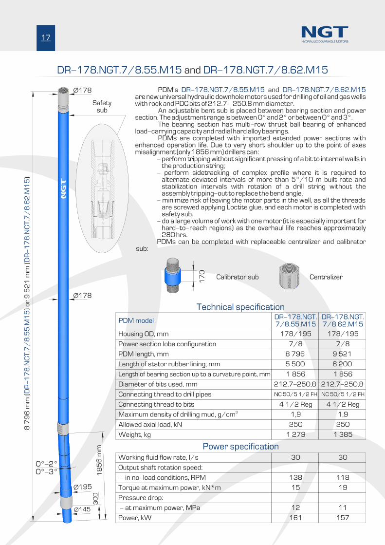
DR-178.NGT.7/8.55.M15 DR-178.NGT.7/8.62.M15 and
PDM’s and DR-178.NGT.7/8.55.M15 DR-178.NGT.7/8.62.M15are new universal hydraulic downhole motors used for drilling of oil and gas wells with rock and PDC bits of 212.7 - 250.8 mm diameter. An adjustable bent sub is placed between bearing section and power section. The adjustment range is between 0° and 2° or between 0° and 3°. The bearing section has multi-row thrust ball bearing of enhanced load-carrying capacity and radial hard alloy bearings. PDMs are completed with imported extended power sections with enhanced operation life. Due to very short shoulder up to the point of axes misalignment (only 1856 mm) drillers can:
- perform tripping without significant pressing of a bit to internal walls in the production string;
- perform sidetracking of complex profile where it is required to alternate deviated intervals of more than 5°/10 m built rate and stabilization intervals with rotation of a drill string without the assembly tripping-out to replace the bend angle.
- minimize risk of leaving the motor parts in the well, as all the threads are screwed applying Loctite glue, and each motor is completed with safety sub.
- do a large volume of work with one motor (it is especially important for hard-to-reach regions) as the overhaul life reaches approximately 280 hrs.
PDMs can be completed with replaceable centralizer and calibrator sub:
Ø195
30
0
Ø145
18
56
mm
0°-2°0°-3°
Ø178
Ø178
7/8 7/8
178/195
DR-178.NGT.7/8.55.Ì15
178/195
DR-178.NGT.7/8.62.Ì15
30 30
1 856 1 856
212,7-250,8 212,7-250,8
5 500 6 200
8 796 9 521
NC 50/5 1/2 FH NC 50/5 1/2 FH
4 1/2 Reg 4 1/2 Reg
1,9 1,9
250 250
1 279 1 385
15 19
138 118
12 11
161 157
8 7
96
mm
()
or
9 5
21
mm
()
DR
M1
5D
RM
15
-1
78
.NG
T.7
/8
.55
.-
17
8.N
GT
.7/
8.6
2.
17
0
17HYDRAULIC DOWNHOLE MOTORS
Power section lobe configuration
Housing OD, mm
PDM model
Working fluid flow rate, l/s
Length of bearing section up to a curvature point, mm
Diameter of bits used, mm
Length of stator rubber lining, mm
PDM length, mm
Connecting thread to drill pipes
Output shaft rotation speed:
Connecting thread to bits3Maximum density of drilling mud, g/cm
Allowed axial load, kN
Weight, kg
Torque at maximum power, kN*m
- in no-load conditions, RPM
Pressure drop:
- at maximum power, MPa
Power, kW
Power specification
Technical specification
Calibrator sub Centralizer
Safetysub
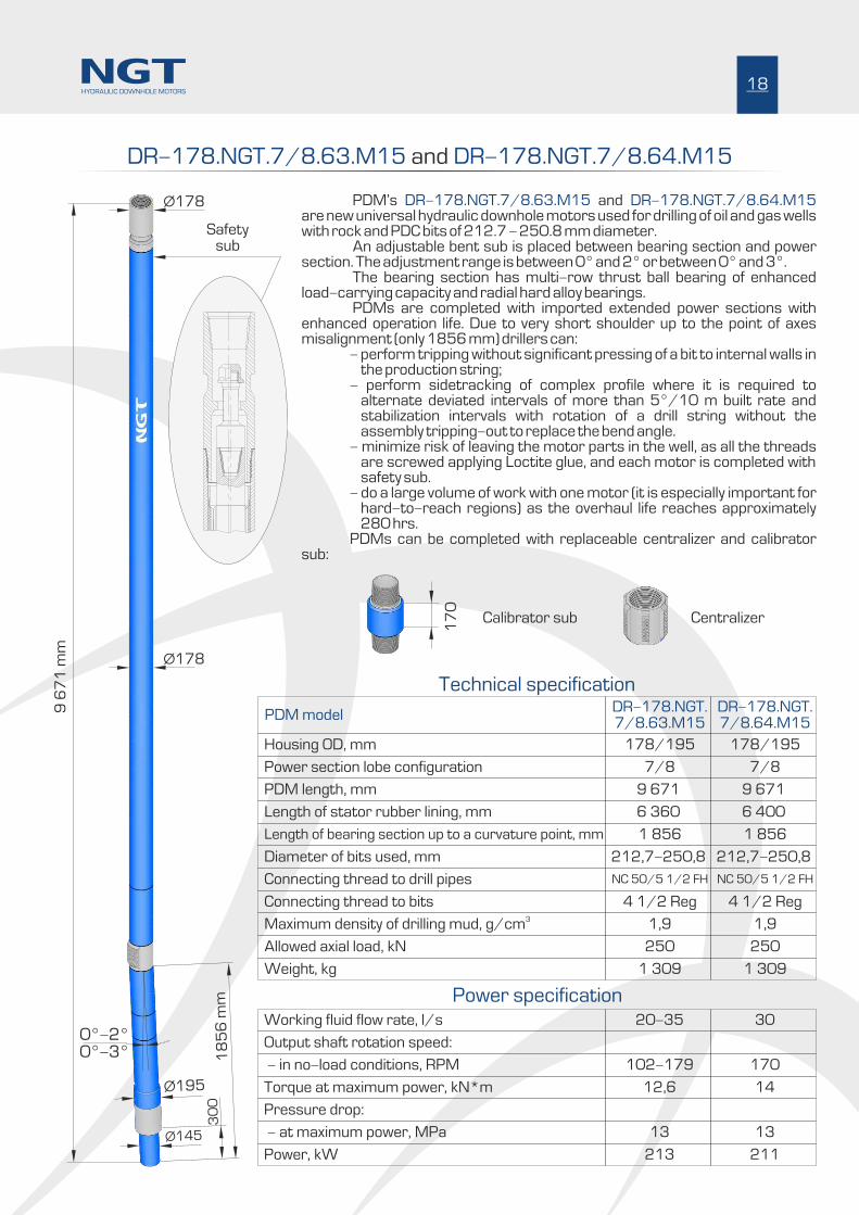
DR-178.NGT.7/8.63.M15 DR-178.NGT.7/8.64.M15 and
PDM’s and DR-178.NGT.7/8.63.M15 DR-178.NGT.7/8.64.M15are new universal hydraulic downhole motors used for drilling of oil and gas wells with rock and PDC bits of 212.7 - 250.8 mm diameter. An adjustable bent sub is placed between bearing section and power section. The adjustment range is between 0° and 2° or between 0° and 3°. The bearing section has multi-row thrust ball bearing of enhanced load-carrying capacity and radial hard alloy bearings. PDMs are completed with imported extended power sections with enhanced operation life. Due to very short shoulder up to the point of axes misalignment (only 1856 mm) drillers can:
- perform tripping without significant pressing of a bit to internal walls in the production string;
- perform sidetracking of complex profile where it is required to alternate deviated intervals of more than 5°/10 m built rate and stabilization intervals with rotation of a drill string without the assembly tripping-out to replace the bend angle.
- minimize risk of leaving the motor parts in the well, as all the threads are screwed applying Loctite glue, and each motor is completed with safety sub.
- do a large volume of work with one motor (it is especially important for hard-to-reach regions) as the overhaul life reaches approximately 280 hrs.
PDMs can be completed with replaceable centralizer and calibrator sub:
18
Ø195
30
0
Ø145
18
56
mm
0°-2°0°-3°
Ø178
Ø178
7/8 7/8
178/195
DR-178.NGT.7/8.63.Ì15
178/195
DR-178.NGT.7/8.64.Ì15
20-35 30
NC 50/5 1/2 FH NC 50/5 1/2 FH
4 1/2 Reg 4 1/2 Reg
1,9 1,9
250 250
1 309 1 309
12,6 14
102-179 170
13 13
213 211
9 6
71
mm
1 856 1 856
212,7-250,8 212,7-250,8
6 360 6 400
9 671 9 671
17
0
HYDRAULIC DOWNHOLE MOTORS
Calibrator sub Centralizer
Power specification
Technical specification
Power section lobe configuration
Housing OD, mm
PDM model
Working fluid flow rate, l/s
Length of bearing section up to a curvature point, mm
Diameter of bits used, mm
Length of stator rubber lining, mm
PDM length, mm
Connecting thread to drill pipes
Output shaft rotation speed:
Connecting thread to bits3Maximum density of drilling mud, g/cm
Allowed axial load, kN
Weight, kg
Torque at maximum power, kN*m
- in no-load conditions, RPM
Pressure drop:
- at maximum power, MPa
Power, kW
Safetysub

19
DR 4 5 4 M23 DR 52 M23-178.NGT. / .5 . -178.NGT.7/8. . and
Ø195
30
0
Ø145
18
56
mm
0°-2°0°-3°
Ø178
Ø178
4/5 7/8
178/195
DR-178.NGT.4/5.54.M23
178/195
DR-178.NGT.7/8.52.M23
30 25-40
NC 50/5 1/2 FH NC 50/5 1/2 FH
4 1/2 Reg 4 1/2 Reg
1,9 1,9
250 250
1 273 1 239
10 13,4
248 100-160
13 13
230 164
8 7
51
mm
()
or
8 5
11
mm
()
DR
45
54
23
DR
5M
23
-1
78
.NG
T.
/.
.Ì-
17
8.N
GT
.7/
8.
2.
PDM’s and are DR-178.NGT.4/5.54.M23 DR-178.NGT.7/8.52.M23new universal hydraulic downhole motors used for drilling of oil and gas wells with rock and PDC bits of 212.7 - 250.8 mm diameter. An adjustable bent sub is placed between bearing section and power section. The adjustment range is between 0° and 2° or between 0° and 3°. PDMs are completed with the bearing section of enhanced operational life, exceeding 300 hrs. The bearing section is fitted with the axial sliding bearing, having operating surfaces made of synthetic diamond, and the radial hard alloy bearings. PDMs are completed with imported extended power sections with enhanced operation life. Due to very short shoulder up to the point of axes misalignment (only 1856 mm) drillers can:
- perform tripping without significant pressing of a bit to internal walls in the production string;
- perform sidetracking of complex profile where it is required to alternate deviated intervals of more than 5°/10 m built rate and stabilization intervals with rotation of a drill string without the assembly tripping-out to replace the bend angle.
- minimize risk of leaving the motor parts in the well, as all the threads are screwed applying Loctite glue, and each motor is completed with safety sub.
- do a large volume of work with one motor (it is especially important for hard-to-reach regions) as the overhaul life reaches approximately 350 hrs.
PDMs can be completed with replaceable centralizer and calibrator sub:
1 856 1 856
212,7-250,8 212,7-250,8
5 400 5 210
8 751 8 511
17
0
HYDRAULIC DOWNHOLE MOTORS
Safetysub
Power section lobe configuration
Housing OD, mm
PDM model
Working fluid flow rate, l/s
Length of bearing section up to a curvature point, mm
Diameter of bits used, mm
Length of stator rubber lining, mm
PDM length, mm
Connecting thread to drill pipes
Output shaft rotation speed:
Connecting thread to bits3Maximum density of drilling mud, g/cm
Allowed axial load, kN
Weight, kg
Torque at maximum power, kN*m
- in no-load conditions, RPM
Pressure drop:
- at maximum power, MPa
Power, kW
Power specification
Technical specification
Calibrator sub Centralizer
DR M23 DR M23-178.NGT.7/8.55. -178.NGT.7/8.62. and
20
Ø195
30
0
Ø145
18
56
mm
0°-2°0°-3°
Ø178
Ø178
7/8 7/8
178/195
DR-178.NGT.7/8.55.Ì23
178/195
DR-178.NGT.7/8.62.Ì23
30 30
NC 50/5 1/2 FH NC 50/5 1/2 FH
4 1/2 Reg 4 1/2 Reg
1,9 1,9
250 250
1 279 1 385
15 19
138 118
12 11
161 157
8 7
96
mm
()
or
9 5
21
mm
()
DR
M2
3D
RM
23
-1
78
.NG
T.7
/8
.55
.-
17
8.N
GT
.7/
8.6
2.
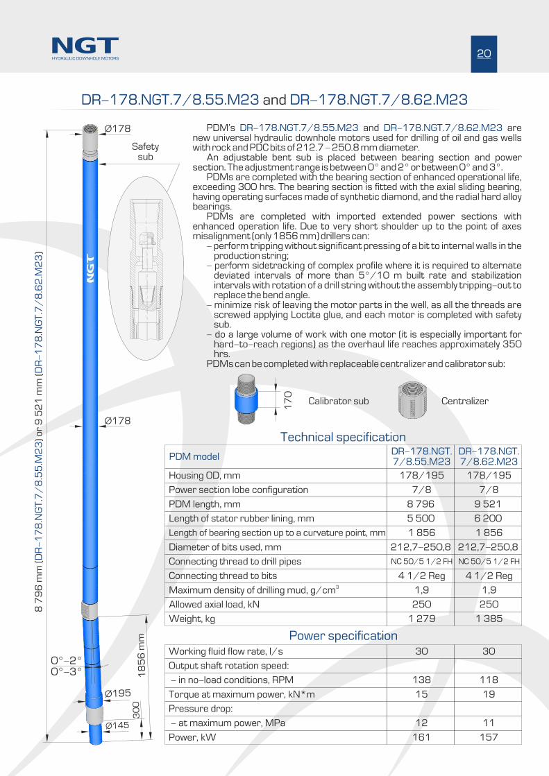
PDM’s and are DR-178.NGT.7/8.55.M23 DR-178.NGT.7/8.62.M23new universal hydraulic downhole motors used for drilling of oil and gas wells with rock and PDC bits of 212.7 - 250.8 mm diameter. An adjustable bent sub is placed between bearing section and power section. The adjustment range is between 0° and 2° or between 0° and 3°. PDMs are completed with the bearing section of enhanced operational life, exceeding 300 hrs. The bearing section is fitted with the axial sliding bearing, having operating surfaces made of synthetic diamond, and the radial hard alloy bearings. PDMs are completed with imported extended power sections with enhanced operation life. Due to very short shoulder up to the point of axes misalignment (only 1856 mm) drillers can: - perform tripping without significant pressing of a bit to internal walls in the
production string; - perform sidetracking of complex profile where it is required to alternate
deviated intervals of more than 5°/10 m built rate and stabilization intervals with rotation of a drill string without the assembly tripping-out to replace the bend angle.
- minimize risk of leaving the motor parts in the well, as all the threads are screwed applying Loctite glue, and each motor is completed with safety sub.
- do a large volume of work with one motor (it is especially important for hard-to-reach regions) as the overhaul life reaches approximately 350 hrs.
PDMs can be completed with replaceable centralizer and calibrator sub:
1 856 1 856
212,7-250,8 212,7-250,8
5 500 6 200
8 796 9 521
HYDRAULIC DOWNHOLE MOTORS
Power section lobe configuration
Housing OD, mm
PDM model
Working fluid flow rate, l/s
Length of bearing section up to a curvature point, mm
Diameter of bits used, mm
Length of stator rubber lining, mm
PDM length, mm
Connecting thread to drill pipes
Output shaft rotation speed:
Connecting thread to bits3Maximum density of drilling mud, g/cm
Allowed axial load, kN
Weight, kg
Torque at maximum power, kN*m
- in no-load conditions, RPM
Pressure drop:
- at maximum power, MPa
Power, kW
17
0
Calibrator sub Centralizer
Technical specification
Power specification
Safetysub
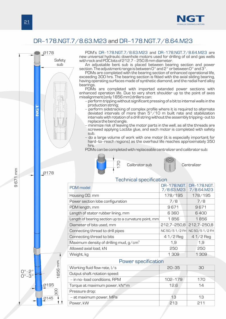
DR-178.NGT.7/8.63.M23 DR-178.NGT.7/8.64.M23 and
Ø195
30
0
Ø145
18
56
mm
0°-2°0°-3°
Ø178
Ø178
7/8 7/8
178/195
DR-178.NGT.7/8.63.M23
178/195
DR-178.NGT.7/8.64.M23
20-35 30
NC 50/5 1/2 FH NC 50/5 1/2 FH
4 1/2 Reg 4 1/2 Reg
1,9 1,9
250 250
1 309 1 309
12,6 14
102-179 170
13 13
213 211
9 6
71
mm
PDM’s and are DR-178.NGT.7/8.63.M23 DR-178.NGT.7/8.64.M23new universal hydraulic downhole motors used for drilling of oil and gas wells with rock and PDC bits of 212.7 - 250.8 mm diameter. An adjustable bent sub is placed between bearing section and power section. The adjustment range is between 0° and 2° or between 0° and 3°. PDMs are completed with the bearing section of enhanced operational life, exceeding 300 hrs. The bearing section is fitted with the axial sliding bearing, having operating surfaces made of synthetic diamond, and the radial hard alloy bearings. PDMs are completed with imported extended power sections with enhanced operation life. Due to very short shoulder up to the point of axes misalignment (only 1856 mm) drillers can: - perform tripping without significant pressing of a bit to internal walls in the
production string; - perform sidetracking of complex profile where it is required to alternate
deviated intervals of more than 5°/10 m built rate and stabilization intervals with rotation of a drill string without the assembly tripping-out to replace the bend angle.
- minimize risk of leaving the motor parts in the well, as all the threads are screwed applying Loctite glue, and each motor is completed with safety sub.
- do a large volume of work with one motor (it is especially important for hard-to-reach regions) as the overhaul life reaches approximately 350 hrs.
PDMs can be completed with replaceable centralizer and calibrator sub:
1 856 1 856
212,7-250,8 212,7-250,8
6 360 6 400
9 671 9 671
21HYDRAULIC DOWNHOLE MOTORS
Power section lobe configuration
Housing OD, mm
PDM model
Working fluid flow rate, l/s
Length of bearing section up to a curvature point, mm
Diameter of bits used, mm
Length of stator rubber lining, mm
PDM length, mm
Connecting thread to drill pipes
Output shaft rotation speed:
Connecting thread to bits3Maximum density of drilling mud, g/cm
Allowed axial load, kN
Weight, kg
Torque at maximum power, kN*m
- in no-load conditions, RPM
Pressure drop:
- at maximum power, MPa
Power, kW
Safetysub
Technical specification
Power specification
17
0
Calibrator sub Centralizer
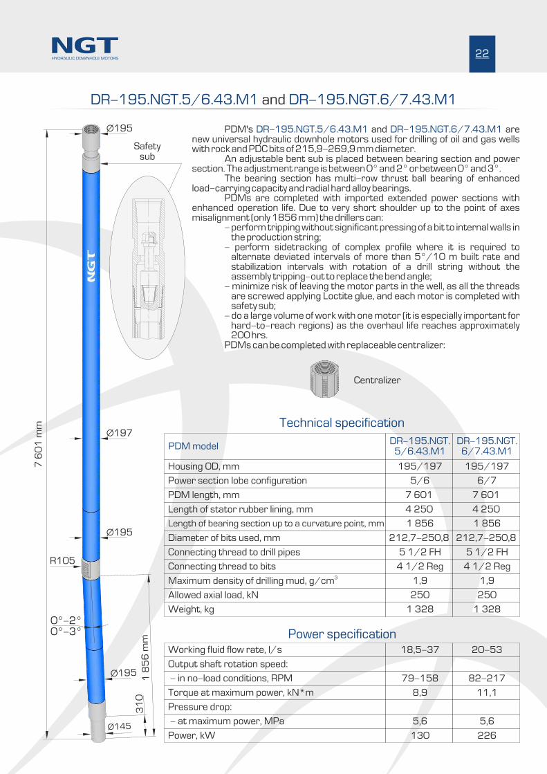
DR-195.NGT.5/6.43.M1 DR-195.NGT.6/7.43.M1 and
PDM's and are DR-195.NGT.5/6.43.M1 DR-195.NGT.6/7.43.M1new universal hydraulic downhole motors used for drilling of oil and gas wells with rock and PDC bits of 215,9-269,9 mm diameter. An adjustable bent sub is placed between bearing section and power section. The adjustment range is between 0° and 2° or between 0° and 3°. The bearing section has multi-row thrust ball bearing of enhanced load-carrying capacity and radial hard alloy bearings. PDMs are completed with imported extended power sections with enhanced operation life. Due to very short shoulder up to the point of axes misalignment (only 1856 mm) the drillers can: - perform tripping without significant pressing of a bit to internal walls in
the production string; - perform sidetracking of complex profile where it is required to
alternate deviated intervals of more than 5°/10 m built rate and stabilization intervals with rotation of a drill string without the assembly tripping-out to replace the bend angle;
- minimize risk of leaving the motor parts in the well, as all the threads are screwed applying Loctite glue, and each motor is completed with safety sub;
- do a large volume of work with one motor (it is especially important for hard-to-reach regions) as the overhaul life reaches approximately 200 hrs.
PDMs can be completed with replaceable centralizer:
22
R105
Ø195
Ø197
Ø195
Ø195
31
0
Ø145
7 6
01
mm
1 8
56
mm
0°-2°0°-3°
Power section lobe configuration
Housing OD, mm
PDM model
Connecting thread to drill pipes
Connecting thread to bits3Maximum density of drilling mud, g/cm
Allowed axial load, kN
Weight, kg
5/6 6/7
195/197
DR-195.NGT.5/6.43.Ì1
195/197
DR-195.NGT.6/7.43.Ì1
18,5-37 20-53
5 1/2 FH 5 1/2 FH
4 1/2 Reg 4 1/2 Reg
1,9 1,9
250 250
1 328 1 328
8,9 11,1
79-158 82-217
5,6 5,6
130 226
Length of bearing section up to a curvature point, mm
Diameter of bits used, mm
Length of stator rubber lining, mm
PDM length, mm
1 856 1 856
212,7-250,8 212,7-250,8
4 250 4 250
7 601 7 601
Centralizer
HYDRAULIC DOWNHOLE MOTORS
Working fluid flow rate, l/s
Output shaft rotation speed:
Torque at maximum power, kN*m
- in no-load conditions, RPM
Pressure drop:
- at maximum power, MPa
Power, kW
Technical specification
Power specification
Safetysub

DR-210.NGT.7/8.42.M1 DR-210.NGT.7/8.50.M1 and
PDM’s and are DR-210.NGT.7/8.42.M1 DR-210.NGT.7/8.50.M1new universal hydraulic downhole motors used for drilling of oil and gas wells with rock and PDC bits of 250,8 – 374.6 mm diameter. An adjustable bent sub is placed between bearing section and power section. The adjustment range is between 0° and 2° or between 0° and 3°. The bearing section has multi-row thrust ball bearing of enhanced load-carrying capacity and radial hard alloy bearings. PDMs are completed with imported extended power sections with enhanced operation life. Due to very short shoulder up to the point of axes misalignment (only 1987 mm) the drillers can:
- perform tripping without significant pressing of a bit to internal walls in the production string;
- perform sidetracking of complex profile where it is required to alternate deviated intervals of more than 5°/10 m built rate and stabilization intervals with rotation of a drill string without the assembly tripping-out to replace the bend angle.
- minimize risk of leaving the motor parts in the well, as all the threads are screwed applying Loctite glue, and each motor is completed with safety sub.
- do a large volume of work with one motor (it is especially important for hard-to-reach regions) as the overhaul life reaches approximately 200 hrs.
23
R122,5
Ø210
Ø210
Ø210
Ø210
29
0
Ø188
1 9
87
mm
0°-2°0°-3°
7/8 7/8
210
DR-210.NGT.7/8.42.M1
210
DR-210.NGT.7/8.50.M1
22,4-44,2 26,3-52,7
6 5/8 Reg 6 5/8 Reg
6 5/8 Reg 6 5/8 Reg
1,9 1,9
300 300
1 570 1 730
13,8 16,2
69-138 121-242
5,6 5,6
179 216
7 7
49
mm
()
or
8 5
49
mm
()
DR
M1
DR
M1
-2
10
.NG
T.7
/8
.42
.-
21
0.N
GT
.7/
8.5
0.
1 987 1 987
250,8-374,6 250,8-374,6
4 200 5 040
7 749 8 549
HYDRAULIC DOWNHOLE MOTORS
Safetysub
Power section lobe configuration
Housing OD, mm
PDM model
Connecting thread to drill pipes
Connecting thread to bits3Maximum density of drilling mud, g/cm
Allowed axial load, kN
Weight, kg
Length of bearing section up to a curvature point, mm
Diameter of bits used, mm
Length of stator rubber lining, mm
PDM length, mm
Working fluid flow rate, l/s
Output shaft rotation speed:
Torque at maximum power, kN*m
- in no-load conditions, RPM
Pressure drop:
- at maximum power, MPa
Power, kW
Technical specification
Power specification
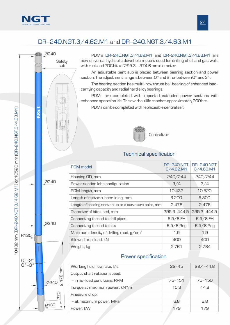
DR-240.NGT.3/4.62.M1 DR-240.NGT.3/4.63.M1 and
PDM’s and are DR-240.NGT.3/4.62.M1 DR-240.NGT.3/4.63.M1
new universal hydraulic downhole motors used for drilling of oil and gas wells
with rock and PDC bits of 295.3 – 374.6 mm diameter.
An adjustable bent sub is placed between bearing section and power
section. The adjustment range is between 0° and 2° or between 0° and 3°.
The bearing section has multi-row thrust ball bearing of enhanced load-
carrying capacity and radial hard alloy bearings.
PDMs are completed with imported extended power sections with
enhanced operation life. The overhaul life reaches approximately 200 hrs.
PDMs can be completed with replaceable centralizer:
24
Power section lobe configuration
Housing OD, mm
PDM model
Working fluid flow rate, l/s
Connecting thread to drill pipes
Output shaft rotation speed:
Connecting thread to bits
3Maximum density of drilling mud, g/cm
Allowed axial load, kN
Weight, kg
3/4 3/4
240/244
DR-240.NGT.3/4.62.M1
240/244
DR-240.NGT.3/4.63.M1
22-45 22,4-44,8
6 5/8 FH 6 5/8 FH
6 5/8 Reg 6 5/8 Reg
1,9 1,9
400 400
2 761 2 784
Technical specification
Power specification
Torque at maximum power, kN*m
- in no-load conditions, RPM
Pressure drop:
15,3 14,8
75-151 75-150
- at maximum power, MPa 6,8 6,8
Power, kW 179 179
Length of bearing section up to a curvature point, mm
Diameter of bits used, mm
Length of stator rubber lining, mm
PDM length, mm
2 478 2 478
295,3-444,5 295,3-444,5
6 200 6 300
10 432 10 520
R125
Ø240
Ø240
Ø240
Ø240
27
0
Ø180
2 4
78
mm
0°-2°0°-3°
10
43
2 m
m (
) o
r 1
05
20
mm
()
DR
24
03
46
2M
1D
R4
34
63
M1
-.N
GT
./
..
-2
0.N
GT
./
..
HYDRAULIC DOWNHOLE MOTORS
Centralizer
Safetysub

DR-240.NGT.5/6.63.M1
PDM is a new universal hydraulic downhole DR-240.NGT.5/6.63.M1
motor used for drilling of oil and gas wells with rock and PDC bits of 295.3 –
374.6 mm diameter.
An adjustable bent sub is placed between bearing section and power
section. The adjustment range is between 0° and 2° or between 0° and 3°.
The bearing section has multi-row thrust ball bearing of enhanced
load-carrying capacity and radial hard alloy bearings.
PDM is completed with imported extended power sections with
enhanced operation life. The overhaul life reaches approximately 200 hrs.
PDM can be completed with replaceable centralizer:
Power section lobe configuration
Housing OD, mm
Working fluid flow rate, l/s
Length of bearing section up to a curvature point, mm
Diameter of bits used, mm
Length of stator rubber lining, mm
PDM length, mm
Connecting thread to drill pipes
Output shaft rotation speed:
Connecting thread to bits
3Maximum density of drilling mud, g/cm
Allowed axial load, kN
Weight, kg
5/6
240/244
27,5-45
2 478
295,3-444,5
6 300
10 520
6 5/8 FH
6 5/8 Reg
1,9
400
2 784
Torque at maximum power, kN*m
- in no-load conditions, RPM
Pressure drop:
19,3
64-129
- at maximum power, MÐa 6,8
Power, kW 234
Power specification
Technical specification
R125
Ø240
Ø240
Ø240
Ø240
27
0
Ø180
2 4
78
mm
0°-2°0°-3°
10
52
0 m
m
25HYDRAULIC DOWNHOLE MOTORS
Safetysub
Centralizer

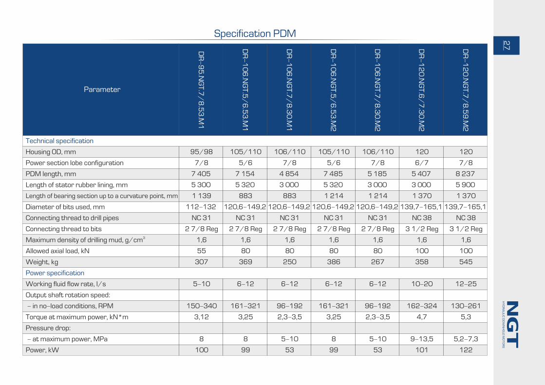
Specification PDM
Power section lobe configuration
Housing OD, mm
Technical specification
Parameter
Working fluid flow rate, l/s
Power specification
Length of bearing section up to a curvature point, mm
Diameter of bits used, mm
Length of stator rubber lining, mm
PDM length, mm
Connecting thread to drill pipes
Output shaft rotation speed:
Connecting thread to bits3Maximum density of drilling mud, g/cm
Allowed axial load, kN
Weight, kg
4/5 4/5 4/5 5/6 5/6 7/8 7/8
76 76/79 76/80 88 88/89 88/89 95/98
D-
76
.NG
T.4
/5
.20
.M1
DO
-7
6.N
GT
.4/
5.2
0.M
1
DR
-7
6.N
GT
.4/
5.2
0.M
2
DR
-8
8.N
GT
.5/
6.2
0.M
1
DR
-8
8.N
GT
.5/
6.2
4.M
1
DR
-8
8.N
GT
.7/
8.2
7.M
1
DR
-9
5.N
GT
.7/
8.4
2.M
1
3-5 3-5 3-5 5-7 4,3-12,8 2,8-8,2 5-10
- 810 855 1 025 1 025 1 025 1 139
83,0-98,4 83,0-98,4 83,0-98,4 98,4-120,6 98,4-120,6 98,4-120,6 112-132
2 000 2 000 2 000 2 000 2 400 2 736 4 180
3 565 3 565 3 646 3 845 4 245 4 581 6 285
2 3/8 Reg 2 3/8 Reg 2 3/8 Reg 2 3/8 Reg 2 3/8 Reg 2 3/8 Reg NC 31
2 3/8 Reg 2 3/8 Reg 2 3/8 Reg 2 3/8 Reg 2 3/8 Reg 2 3/8 Reg 2 7/8 Reg
1,6 1,6 1,6 1,6 1,6 1,6 1,6
25 25 45 50 50 50 55
94 94 97 137 151 162 260
Torque at maximum power, kN*m
- in no-load conditions, RPM
Pressure drop:
0,6-0,8 0,6-0,8 0,6-0,8 1,1-1,3 1,53 1,34 2,46
240-396 240-396 240-396 270-400 108-325 74-215 126-257
- at maximum power, MÐa 8-10 8-10 8-10 10-13 4,5 4,3 5,36
Power, kW 11-25 11-25 11-25 27-43 47 28 60
HY
DR
AU
LIC
DO
WN
HO
LE
MO
TO
RS
26
Parameter
7/8 5/6 7/8 5/6 7/8 6/7 7/8
95/98 105/110 106/110 105/110 106/110 120 120
DR
-9
5.N
GT
.7/
8.5
3.M
1
DR
-1
06
.NG
T.5
/6
.53
.M1
DR
-1
06
.NG
T.7
/8
.30
.M1
DR
-1
06
.NG
T.5
/6
.53
.M2
DR
-1
06
.NG
T.7
/8
.30
.M2
DR
-1
20
.NG
T.6
/7
.30
.M2
DR
-1
20
.NG
T.7
/8
.59
.M2
5-10 6-12 6-12 6-12 6-12 10-20 12-25
1 139 883 883 1 214 1 214 1 370 1 370
112-132 120,6-149,2 120,6-149,2 120,6-149,2 120,6-149,2 139,7-165,1 139,7-165,1
5 300 5 320 3 000 5 320 3 000 3 000 5 900
7 405 7 154 4 854 7 485 5 185 5 407 8 237
NC 31 NC 31 NC 31 NC 31 NC 31 NC 38 NC 38
2 7/8 Reg 2 7/8 Reg 2 7/8 Reg 2 7/8 Reg 2 7/8 Reg 3 1/2 Reg 3 1/2 Reg
1,6 1,6 1,6 1,6 1,6 1,6 1,6
55 80 80 80 80 100 100
307 369 250 386 267 358 545
3,12 3,25 2,3-3,5 3,25 2,3-3,5 4,7 5,3
150-340 161-321 96-192 161-321 96-192 162-324 130-261
8 8 5-10 8 5-10 9-13,5 5,2-7,3
100 99 53 99 53 101 122
27
HY
DR
AU
LIC
DO
WN
HO
LE
MO
TO
RS
Power section lobe configuration
Housing OD, mm
Working fluid flow rate, l/s
Length of bearing section up to a curvature point, mm
Diameter of bits used, mm
Length of stator rubber lining, mm
PDM length, mm
Connecting thread to drill pipes
Output shaft rotation speed:
Connecting thread to bits3Maximum density of drilling mud, g/cm
Allowed axial load, kN
Weight, kg
Torque at maximum power, kN*m
- in no-load conditions, RPM
Pressure drop:
- at maximum power, MÐa
Power, kW
Technical specification
Power specification
Specification PDM

7/8 7/8 4/5 7/8 7/8 7/8 7/8 7/8
165 165 178/195 178/195 178/195 178/195 178/195 178/195
DR
-1
65
.NG
T.7
/8
.58
.M1
DR
-1
65
.NG
T.7
/8
.69
.M1
DR
-1
78
.NG
T.4
/5
.54
.M1
5
DR
-1
78
.NG
T.4
/5
.54
.M2
3
DR
-1
78
.NG
T.7
/8
.52
.M1
5
DR
-1
78
.NG
T.7
/8
.52
.M2
3
DR
-1
78
.NG
T.7
/8
.55
.M1
5
DR
-1
78
.NG
T.7
/8
.55
.M2
3
DR
-1
78
.NG
T.7
/8
.62
.M1
5
DR
-1
78
.NG
T.7
/8
.62
.M2
3
DR
-1
78
.NG
T.7
/8
.63
.M1
5
DR
-1
78
.NG
T.7
/8
.63
.M2
3
DR
-1
78
.NG
T.7
/8
.64
.M1
5
DR
-1
78
.NG
T.7
/8
.64
.M2
3
17-38 17-38 30 25-40 30 30 20-35 30
1 856 1 856 1 856 1 856 1 856 1 856 1 856 1 856
190,5-250,8 190,5-250,8 212,7-250,8 212,7-250,8 212,7-250,8 212,7-250,8 212,7-250,8 212,7-250,8
5 720 6 880 5 400 5 210 5 500 6 200 6 360 6 400
9 111 10 271 8 751 8 511 8 796 9 521 9 671 9 671
NC 50 NC 50 NC 50/5 1/2 FH NC 50/5 1/2 FH NC 50/5 1/2 FH NC 50/5 1/2 FH NC 50/5 1/2 FH NC 50/5 1/2 FH
4 1/2 Reg 4 1/2 Reg 4 1/2 Reg 4 1/2 Reg 4 1/2 Reg 4 1/2 Reg 4 1/2 Reg 4 1/2 Reg
1,9 1,9 1,9 1,9 1,9 1,9 1,9 1,9
250 250 250 250 250 250 250 250
1 138 1 283 1 273 1 239 1 279 1 385 1 309 1 309
10,9 13,1 10 13,4 15 19 12,6 14
71-160 71-160 248 100-160 138 118 102-179 170
7 7 13 13 12 11 13 13
164 197 230 164 161 157 213 211
28
HY
DR
AU
LIC
DO
WN
HO
LE
MO
TO
RS
Power section lobe configuration
Housing OD, mm
Working fluid flow rate, l/s
Length of bearing section up to a curvature point, mm
Diameter of bits used, mm
Length of stator rubber lining, mm
PDM length, mm
Connecting thread to drill pipes
Output shaft rotation speed:
Connecting thread to bits3Maximum density of drilling mud, g/cm
Allowed axial load, kN
Weight, kg
Torque at maximum power, kN*m
- in no-load conditions, RPM
Pressure drop:
- at maximum power, MÐa
Power, kW
Technical specification
Power specification
Specification PDM
Parameter

5/6 6/7 7/8 7/8 3/4 3/4 5/6
195/197 195/197 210 210 240/244 240/244 240/244
DR
-1
95
.NG
T.5
/6
.43
.M1
DR
-1
95
.NG
T.6
/7
.43
.M1
DR
-2
10
.NG
T.7
/8
.42
.M1
DR
-2
10
.NG
T.7
/8
.50
.M1
DR
-2
40
.NG
T.3
/4
.62
.M1
DR
-2
40
.NG
T.3
/4
.63
.M1
DR
-2
40
.NG
T.5
/6
.63
.M1
18,5-37 20-53 22,4-44,2 26,3-52,7 22-45 22,4-44,8 27,5-45
1 856 1 856 1 987 1 987 2 478 2 478 2 478
212,7-250,8 212,7-250,8 250,8-374,6 250,8-374,6 295,3-444,5 295,3-444,5 295,3-444,5
4 250 4 250 4 200 5 040 6 200 6 300 6 300
7 601 7 601 7 749 8 549 10 432 10 520 10 520
5 1/2 FH 5 1/2 FH 6 5/8 Reg 6 5/8 Reg 6 5/8 FH 6 5/8 FH 6 5/8 FH
4 1/2 Reg 4 1/2 Reg 6 5/8 Reg 6 5/8 Reg 6 5/8 Reg 6 5/8 Reg 6 5/8 Reg
1,9 1,9 1,9 1,9 1,9 1,9 1,9
250 250 300 300 400 400 400
1 328 1 328 1 570 1 730 2 761 2 784 2 784
8,9 11,1 13,8 16,2 15,3 14,8 19,3
79-158 82-217 69-138 121-242 75-151 75-150 64-129
5,6 5,6 5,6 5,6 6,8 6,8 6,8
130 226 179 216 179 179 234
29
HY
DR
AU
LIC
DO
WN
HO
LE
MO
TO
RS
Power section lobe configuration
Housing OD, mm
Working fluid flow rate, l/s
Length of bearing section up to a curvature point, mm
Diameter of bits used, mm
Length of stator rubber lining, mm
PDM length, mm
Connecting thread to drill pipes
Output shaft rotation speed:
Connecting thread to bits3Maximum density of drilling mud, g/cm
Allowed axial load, kN
Weight, kg
Torque at maximum power, kN*m
- in no-load conditions, RPM
Pressure drop:
- at maximum power, MÐa
Power, kW
Technical specification
Power specification
Parameter
Specification PDM

30
HY
DR
AU
LIC
DO
WN
HO
LE
MO
TO
RS

Bearing sections for turbodrills and PDM
Production of bearing sections for PDMs and turbodrills is the main direction of the company's activity. The complete cycle of operations on the bearing section production is provided: design, prototype production, stand and field tests, design improvement, production of commercial batches, service.
As the result of significant increase of power and torque, when using long length power section PDMs of foreign production, the problem has occurred which is reliability and durability of all the transmission members (clutches, universal joints, threads, shafts of bearing sections) transferring the torque from the PDM rotor to bit.
Our company has carried out a large volume of works to increase load-carrying capacity of the transmission members of the PDM's within the range of 76 – 244 mm. Production of the bearing sections featuring enhanced operation life has been mastered.
Main advantages of the bearing sections developed and produced by our company:
1. Due to the short shoulder, drillers are able to perform Short lower shoulder to the bend angle point. PDM tripping without considerable pressing of a bit to internal borehole walls. It is possible to drill without pulling out of the assembly to change the bend angle while complicated profile sidetracking where it is required to alternate the sections of borehole deviation with the build rate exceeding 5°/10 m and the sections of stabilization with drill string rotation.
2. Bearing sections of our production, having multi-raw thrust ball bearing as an Enhanced operation life.axial bearing, have enhanced operation life. Its average overhaul period is 200 – 280 hours. Bearing sections of three standard sizes (106, 120 and 178 mm) are designed to have even more enhanced operation life. The bearing sections are fitted with the axial sliding bearing, the operating surfaces made of synthetic diamond. Average overhaul period is 300 – 350 hours.
3. are the result of increase of the universal joint OD and use of Powerful double-hinged universal joints large diameter balls. Load-carrying capacity and durability of the universal joint have been increased significantly. Rubber cups are produced out of special rubber at the aircraft factory. The friction pair “mushroom-insert” is made out of steel and bronze selected under the recommendations of Sukhoy Engineering Department which are used in aircraft building for production of sliding bearings.
4. is multi-row radial-thrust ball bearing of enhanced load-carrying Bearing section axial bearing capacity. The company has organized production of ball bearings. Modifying different members of axial bearing (rolling bearing profile, ball diameters, retainer sizes) at the stage of development and production, the following has been obtained:
- significant increase of load-carrying capacity of the axial bearings compared with the bearings of commercial production of the same overall sizes,
- extension of the range: the company produces the bearings of non-standard overall sizes for both - new designs and repair of imported bearing sections,
- best possible material: the bearings are made of imported silicomolybdic steel of vacuum-arc remelting, featuring high impact resilience and strength,
- high accuracy: due to high accuracy, while producing the bearing retainers, distribution of the load among the rows and, therefore, high load-carrying capacity and durability are obtained.
5. impregnated with hard alloy plates is placed at minimum available Reinforced lower radial bearing distance from the bit. The bearing advantages are:
- high mechanical properties of the casing: the radial bearing casing is produced of alloy steel, retaining high hardness and strength after sintering procedure, that allows the bearing to thread and use it as the bearing section nipple nut,
- high wear-resistance. Friction surfaces of the bearings are reinforced with hard alloy plates.
6. . The shaft blanks are forged on Forged blanks for bearing section shafts and universal joint shaftsradial-forging machine. During forging procedure the internal structure of metal is compressed, internal fibers, taking the form of the shaft surface that improves the mechanical properties significantly. This leads to significant reduction of the shaft damage risk at the places of diameter change.
7. While assembling hydraulic downhole All critical threaded connections are assembled using glue.motors (DHM), thread glues of different fixation degree of the companies 3M are used.
31HYDRAULIC DOWNHOLE MOTORS

216
263
222
290
257
277
Performance of 13 bearing sections run in the Tatarstan Republic
PDM model,Serial number
Cumulativeoperating time,
hour
Quantity ofrepairs, pcs
On PDM
Interrepair time, hour
Average
S-178.NGT.M14, number 223
871
642
919
641
988
538
937
865
789
666
871
513
830
4
2
4
2
2
1
3
4
3
3
3
2
3
218
321
230
321
494
538
312
280
In 2011-2013 13 positive displacement motors of 178 mm dia. run under control in
cooperation with RIPNO Ltd. - Tatarstan. The bearing sections used were: and S-178.NGT.M14
S-178.NGT.M16. The PDM's lessee was Bureniye Ltd. 13 positive displacement motors had
average overhaul period exceeding 280 hrs, proving high stable quality of the drilling equipment
developed and produced at JSC «NGT».
S-178.NGT.M14, number 225
S-178.NGT.M16, number 1
S-178.NGT.M16, number 3
S-178.NGT.M16, number 5
S-178.NGT.M16, number 7
S-178.NGT.M16, number 10
S-178.NGT.M14, number 224
S-178.NGT.M14, number 226
S-178.NGT.M16, number 2
S-178.NGT.M16, number 4
S-178.NGT.M16, number 6
S-178.NGT.M16, number 9
32HYDRAULIC DOWNHOLE MOTORS

S-178.NGT.M15
JSC «NGT» offers wide range of bearing sections for turbodrills and positive displacement motors to its customers. For convenience of the catalogue use, please, see the designation structure of bearing sections:
Number of bearing section modification
Standard size
Bearing section designation
Bearing sections presented in the catalogue:
Bearing section designation
33
S-76.NGT.M2
S-88.NGT.M1
S-95.NGT.M1
S-106.NGT.M1
S-106.NGT.M2
S-120.NGT.M2
S-165.NGT.M1
S-178.NGT.M12
S-178.NGT.M15
S-178.NGT.M16
S-178.NGT.M23
S-195.NGT.M4
S-210.NGT.M1
S-240.NGT.M1
HYDRAULIC DOWNHOLE MOTORS

S-76.NGT.M2
Bearing section is a new short bearing S-76.NGT.M2
section featuring enhanced operation life.
The bearing section is used in PDM power sections of 76
mm dia. and for:
- well rehabilitation in housing pipes;
- well drilling with bits of 83 – 98.4 mm diameter.
Axial bearing of bearing section is a multi-row thrust ball
bearing with toroidal raceways, radial bearings of bearing
section are steel sleeves, having the friction surfaces
reinforced with hard-alloy plates.
The bearing section is furnished with drive shaft with two
joints to connect to the power section rotor. The bearing
section design has adjustable bent sub. The adjustment range
is from 0° up to 2° or from 0° up to 3°.
Meeting customers' requirements, the bearing section
can be produced with the connecting threads for specific
power section.
Top sub (safety sub) is available with the bearing section
to connect the power section to drill pipes
Housing OD, mm
Bearing section length, mm
Range of angle adjuster change, degree
Bearing section length to curvature plane, mm
Connecting thread to bit
Torque transmitted, max. kN*m
Tolerance of axial loading, kN
Overhaul period, hour
80
1 227
0-2 èëè 0-3
855
2 3/8 Reg
3,0
45
200
855
1 2
27
mm
Thread torotor
Thread tostator
R43,5
Ж80
Ж80
0-2°0-3°
Ж76
Technical specifications
34HYDRAULIC DOWNHOLE MOTORS

Bearing section is a new short bearing S-88.NGT.M1
section featuring enhanced operation life.
The bearing section is used in PDM power sections of 88
- 89 mm dia. and for:
- drilling of oil and gas wells;
- well reconstruction by sidetracking with rock and PDC
bits, including bicentric ones, with the diameter of
98.4 – 120.6 mm;
- well workover.
Axial bearing of bearing section is a multi-row thrust ball
bearing with toroidal raceways, radial bearings of bearing
section are steel sleeves, having the friction surfaces
reinforced with hard-alloy plates.
The bearing section is furnished with drive shaft with two
joints to connect to the power section rotor. The bearing
section design has adjustable bent sub. The adjustment range
is from 0° up to 2° or from 0° up to 3°.
Meeting customers' requirements, the bearing section
can be produced with the connecting threads for specific
power section.
Top sub (safety sub) is available with the bearing section
to connect the power section to drill pipes.
88
1 405
0-2 èëè 0-3
1 025
2 3/8 Reg
2,0
55
S-88.NGT.M1
1025
14
05
mm
R49
Ж88
Ж88
0-2°0-3°
Ж80
200
35HYDRAULIC DOWNHOLE MOTORS
Thread torotor
Thread tostator
Housing OD, mm
Bearing section length, mm
Range of angle adjuster change, degree
Bearing section length to curvature plane, mm
Connecting thread to bit
Torque transmitted, max. kN*m
Tolerance of axial loading, kN
Overhaul period, hour
Technical specifications
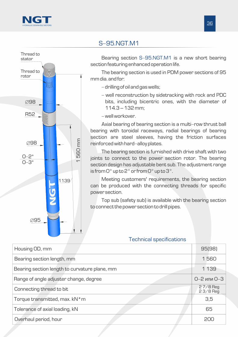
Bearing section is a new short bearing S-95.NGT.M1
section featuring enhanced operation life.
The bearing section is used in PDM power sections of 95
mm dia. and for:
- drilling of oil and gas wells;
- well reconstruction by sidetracking with rock and PDC
bits, including bicentric ones, with the diameter of
114.3 – 132 mm;
- well workover.
Axial bearing of bearing section is a multi-row thrust ball
bearing with toroidal raceways, radial bearings of bearing
section are steel sleeves, having the friction surfaces
reinforced with hard-alloy plates.
The bearing section is furnished with drive shaft with two
joints to connect to the power section rotor. The bearing
section design has adjustable bent sub. The adjustment range
is from 0° up to 2° or from 0° up to 3°.
Meeting customers' requirements, the bearing section
can be produced with the connecting threads for specific
power section.
Top sub (safety sub) is available with the bearing section
to connect the power section to drill pipes.
95(98)
1 560
0-2 èëè 0-3
1 139
2 7/8 Reg2 3/8 Reg
3,5
65
200
S-95.NGT.M1
1139
1 5
60
mm
R52
Ж98
Ж98
0-2°0-3°
Ж95
36HYDRAULIC DOWNHOLE MOTORS
Housing OD, mm
Bearing section length, mm
Range of angle adjuster change, degree
Bearing section length to curvature plane, mm
Connecting thread to bit
Torque transmitted, max. kN*m
Tolerance of axial loading, kN
Overhaul period, hour
Technical specifications
Thread torotor
Thread tostator

S-106.NGT.M1
Bearing section is a new ultra-short S-106.NGT.M1
bearing section featuring enhanced operation life.
The bearing section is used in PDM power sections of
106 mm dia. and for:
- drilling of oil and gas wells;
- well reconstruction by sidetracking with rock and
PDC bits, including bicentric ones, with the diameter
of 120.6 – 149.2 mm;
- well workover.
The bearing section is fitted with the axial sliding bearing,
having operating surfaces made of synthetic diamond, and the
radial hard alloy bearings.
The bearing section is furnished with drive shaft with two
joints to connect to the power section rotor. The bearing
section design has adjustable bent sub. The adjustment range
is from 0° up to 2° or from 0° up to 3°.
Meeting customers' requirements, the bearing section
can be produced with the connecting threads for specific
power section.
Top sub (safety sub) is available with the bearing section
to connect the power section to drill pipes.
106
1 309
0-2 èëè 0-3
883
2 7/8 Reg
5,0
80
300
883
1 3
09
mm
R59
Ж106
Ж110
0-2°0-3°
Ж100
37HYDRAULIC DOWNHOLE MOTORS
Housing OD, mm
Bearing section length, mm
Range of angle adjuster change, degree
Bearing section length to curvature plane, mm
Connecting thread to bit
Torque transmitted, max. kN*m
Tolerance of axial loading, kN
Overhaul period, hour
Technical specifications
Thread torotor
Thread tostator
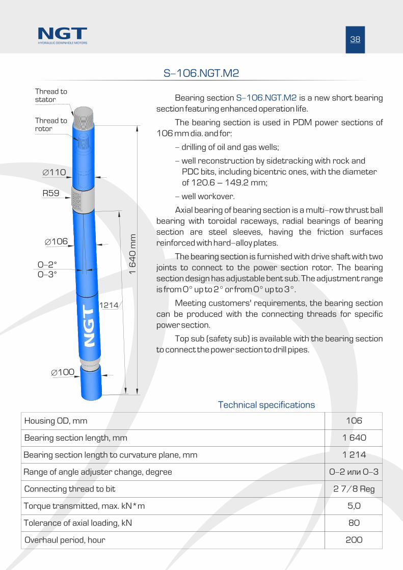
Bearing section is a new short bearing S-106.NGT.M2
section featuring enhanced operation life.
The bearing section is used in PDM power sections of
106 mm dia. and for:
- drilling of oil and gas wells;
- well reconstruction by sidetracking with rock and
PDC bits, including bicentric ones, with the diameter
of 120.6 – 149.2 mm;
- well workover.
Axial bearing of bearing section is a multi-row thrust ball
bearing with toroidal raceways, radial bearings of bearing
section are steel sleeves, having the friction surfaces
reinforced with hard-alloy plates.
The bearing section is furnished with drive shaft with two
joints to connect to the power section rotor. The bearing
section design has adjustable bent sub. The adjustment range
is from 0° up to 2° or from 0° up to 3°.
Meeting customers' requirements, the bearing section
can be produced with the connecting threads for specific
power section.
Top sub (safety sub) is available with the bearing section
to connect the power section to drill pipes.
106
1 640
0-2 èëè 0-3
1 214
2 7/8 Reg
5,0
80
200
S-106.NGT.M2
1214
1 6
40
mm
R59
Ж106
Ж110
0-2°0-3°
Ж100
38HYDRAULIC DOWNHOLE MOTORS
Housing OD, mm
Bearing section length, mm
Range of angle adjuster change, degree
Bearing section length to curvature plane, mm
Connecting thread to bit
Torque transmitted, max. kN*m
Tolerance of axial loading, kN
Overhaul period, hour
Technical specifications
Thread torotor
Thread tostator

Bearing section is a new short bearing S-120.NGT.M2
section featuring enhanced operation life.
The bearing section is used in PDM power sections of
120 - 127 mm dia. and for:
- drilling of oil and gas wells;
- well reconstruction by sidetracking with rock and
PDC bits, including bicentric ones, with the diameter
of 132 – 165.1 mm;
- well workover.
Axial bearing of bearing section is a multi-row thrust ball
bearing with toroidal raceways, radial bearings of bearing
section are steel sleeves, having the friction surfaces
reinforced with hard-alloy plates.
The bearing section is furnished with drive shaft with two
joints to connect to the power section rotor. The bearing
section design has adjustable bent sub. The adjustment range
is from 0° up to 2° or from 0° up to 3°.
Meeting customers' requirements, the bearing section
can be produced with the connecting threads for specific
power section.
Top sub (safety sub) is available with the bearing section
to connect the power section to drill pipes.
120
1 856
0-2 èëè 0-3
1 370
3 1/2 Reg
6,0
100
200
S-120.NGT.M2
1 8
56
mm
R62,5
Ж120
Ж120
0-2°0-3°
Ж110
1370
39HYDRAULIC DOWNHOLE MOTORS
Housing OD, mm
Bearing section length, mm
Range of angle adjuster change, degree
Bearing section length to curvature plane, mm
Connecting thread to bit
Torque transmitted, max. kN*m
Tolerance of axial loading, kN
Overhaul period, hour
Technical specifications
Thread torotor
Thread tostator
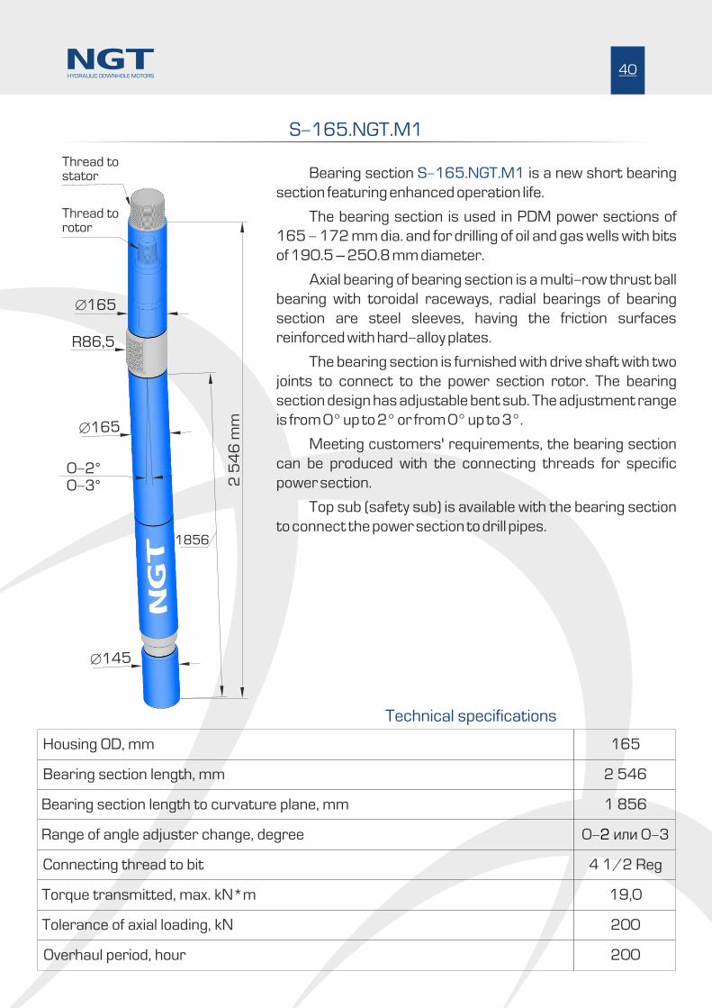
Bearing section is a new short bearing S-165.NGT.M1
section featuring enhanced operation life.
The bearing section is used in PDM power sections of
165 - 172 mm dia. and for drilling of oil and gas wells with bits
of 190.5 – 250.8 mm diameter.
Axial bearing of bearing section is a multi-row thrust ball
bearing with toroidal raceways, radial bearings of bearing
section are steel sleeves, having the friction surfaces
reinforced with hard-alloy plates.
The bearing section is furnished with drive shaft with two
joints to connect to the power section rotor. The bearing
section design has adjustable bent sub. The adjustment range
is from 0° up to 2° or from 0° up to 3°.
Meeting customers' requirements, the bearing section
can be produced with the connecting threads for specific
power section.
Top sub (safety sub) is available with the bearing section
to connect the power section to drill pipes.
165
2 546
0- èëè 0-32
1 856
4 1/2 Reg
19,0
200
200
S-165.NGT.M1
2 5
46
mm
R86,5
Ж165
Ж165
0-2°0-3°
Ж145
1856
40HYDRAULIC DOWNHOLE MOTORS
Housing OD, mm
Bearing section length, mm
Range of angle adjuster change, degree
Bearing section length to curvature plane, mm
Connecting thread to bit
Torque transmitted, max. kN*m
Tolerance of axial loading, kN
Overhaul period, hour
Technical specifications
Thread torotor
Thread tostator
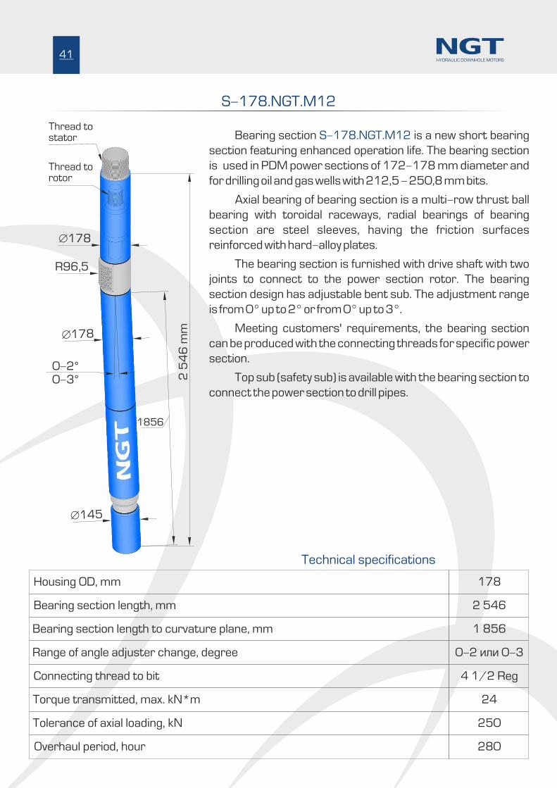
S-178.NGT.M12
Bearing section is a new short bearing S-178.NGT.M12
section featuring enhanced operation life. The bearing section
is used in PDM power sections of 172-178 mm diameter and
for drilling oil and gas wells with 212,5 - 250,8 mm bits.
Axial bearing of bearing section is a multi-row thrust ball
bearing with toroidal raceways, radial bearings of bearing
section are steel sleeves, having the friction surfaces
reinforced with hard-alloy plates.
The bearing section is furnished with drive shaft with two
joints to connect to the power section rotor. The bearing
section design has adjustable bent sub. The adjustment range
is from 0° up to 2° or from 0° up to 3°.
Meeting customers' requirements, the bearing section
can be produced with the connecting threads for specific power
section.
Top sub (safety sub) is available with the bearing section to
connect the power section to drill pipes.
178
2 546
0-2 èëè 0-3
1 856
4 1/2 Reg
24
250
280
1856
2 5
46
mm
R96,5
Ж178
Ж178
0-2°0-3°
Ж145
41HYDRAULIC DOWNHOLE MOTORS
Housing OD, mm
Bearing section length, mm
Range of angle adjuster change, degree
Bearing section length to curvature plane, mm
Connecting thread to bit
Torque transmitted, max. kN*m
Tolerance of axial loading, kN
Overhaul period, hour
Technical specifications
Thread torotor
Thread tostator

S-178.NGT.M15
Bearing section is a new short bearing S-178.NGT.M15
section featuring enhanced operation life. The bearing section
is used in PDM power sections of 172 – 178 mm diameter and
for drilling oil and gas wells with 212,5 - 250,8 mm bits.
Axial bearing of bearing section is a multi-row thrust ball
bearing with toroidal raceways, radial bearings of bearing
section are steel sleeves, having the friction surfaces
reinforced with hard-alloy plates.
The bearing section is furnished with drive shaft with two
joints to connect to the power section rotor. The bearing
section design has adjustable bent sub. The adjustment range
is from 0° up to 2° or from 0° up to 3°.
Meeting customers' requirements, the bearing section
can be produced with the connecting threads for specific power
section.
Top sub (safety sub), also replaceable centralizer and
calibrator sub are available with the bearing section to connect
the power section to drill pipes:
178
2 546
0-2 èëè 0-3
1 856
4 1/2 Reg
24
250
280
2 5
46
mm
R96,5
Ж178
Ж178
0-2°0-3°
Ж145
1856
Ж195
17
0
Calibrator
sub
24
5
Centralizer
or other
Ж210
42HYDRAULIC DOWNHOLE MOTORS
Thread torotor
Thread tostator
Housing OD, mm
Bearing section length, mm
Range of angle adjuster change, degree
Bearing section length to curvature plane, mm
Connecting thread to bit
Torque transmitted, max. kN*m
Tolerance of axial loading, kN
Overhaul period, hour
Technical specifications
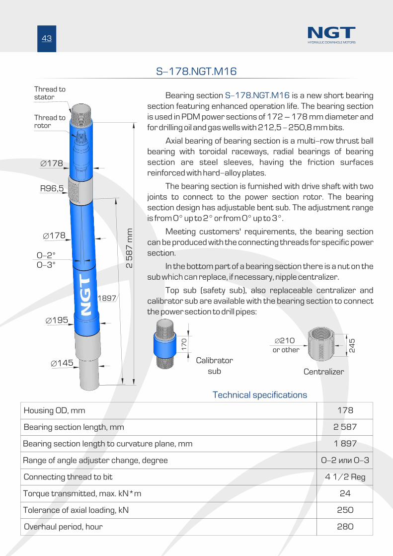
S-178.NGT.M16
Bearing section is a new short bearing S-178.NGT.M16
section featuring enhanced operation life. The bearing section
is used in PDM power sections of 172 – 178 mm diameter and
for drilling oil and gas wells with 212,5 - 250,8 mm bits.
Axial bearing of bearing section is a multi-row thrust ball
bearing with toroidal raceways, radial bearings of bearing
section are steel sleeves, having the friction surfaces
reinforced with hard-alloy plates.
The bearing section is furnished with drive shaft with two
joints to connect to the power section rotor. The bearing
section design has adjustable bent sub. The adjustment range
is from 0° up to 2° or from 0° up to 3°.
Meeting customers' requirements, the bearing section
can be produced with the connecting threads for specific power
section.
In the bottom part of a bearing section there is a nut on the
sub which can replace, if necessary, nipple centralizer.
Top sub (safety sub), also replaceable centralizer and
calibrator sub are available with the bearing section to connect
the power section to drill pipes:
178
2 587
0-2 èëè 0-3
1 897
4 1/2 Reg
24
250
280
17
0
24
5
2 5
87
mm
R96,5
Ж178
Ж178
0-2°0-3°
Ж145
1897
Ж195
43HYDRAULIC DOWNHOLE MOTORS
Calibrator
sub Centralizer
or other
Ж210
Thread torotor
Thread tostator
Technical specifications
Housing OD, mm
Bearing section length, mm
Range of angle adjuster change, degree
Bearing section length to curvature plane, mm
Connecting thread to bit
Torque transmitted, max. kN*m
Tolerance of axial loading, kN
Overhaul period, hour

S-178.NGT.M23
Bearing section is a new short bearing S-178.NGT.M23
section featuring enhanced overhaul period of around 350
hours. The bearing section is used in PDM power sections of
172 – 178 mm diameter and for drilling oil and gas wells with
212,5 - 250,8 mm bits.
The bearing section is fitted with the axial sliding bearing,
having operating surfaces made of synthetic diamond, and the
radial hard alloy bearings.
The bearing section is furnished with drive shaft with two
joints to connect to the power section rotor. The bearing
section design has adjustable bent sub. The adjustment range
is from 0° up to 2° or from 0° up to 3°.
Meeting customers' requirements, the bearing section
can be produced with the connecting threads for specific power
section.
Top sub (safety sub), also replaceable centralizer and
calibrator sub are available with the bearing section to connect
the power section to drill pipes:
178
2 546
0-2 èëè 0-3
1 856
4 1/2 Reg
24
250
350
17
0
24
5
2 5
46
mm
R96,5
Ж178
Ж178
0-2°0-3°
Ж145
1856
Ж195
44HYDRAULIC DOWNHOLE MOTORS
Calibrator
sub Centralizer
or other
Ж210
Technical specifications
Housing OD, mm
Bearing section length, mm
Range of angle adjuster change, degree
Bearing section length to curvature plane, mm
Connecting thread to bit
Torque transmitted, max. kN*m
Tolerance of axial loading, kN
Overhaul period, hour
Thread torotor
Thread tostator

Bearing section is a new short bearing S-195.NGT.M4
section featuring enhanced operation life. The bearing section
is used in PDM power sections of 195 mm diameter and for
drilling oil and gas wells with 215.9 – 269.9 mm rock and PDC
bits.
Axial bearing of bearing section is a multi-row thrust ball
bearing with toroidal raceways, radial bearings of bearing
section are steel sleeves, having the friction surfaces
reinforced with hard-alloy plates.
The bearing section is furnished with drive shaft with two
joints to connect to the power section rotor. The bearing
section design has adjustable bent sub. The adjustment range
is from 0° up to 2° or from 0° up to 3°.
Meeting customers' requirements, the bearing section
can be produced with the connecting threads for specific
power section.
Top sub (safety sub) and replaceable centralizer are
available with the bearing section to connect the power
section to drill pipes:
195
2 546
0-2 èëè 0-3
1 856
4 1/2 Reg
27,0
250
250
S-195.NGT.M4
2 5
46
mm
R105
Ж195
Ж195
0-2°0-3°
Ж145
1856
Ж195
45HYDRAULIC DOWNHOLE MOTORS
Technical specifications
Housing OD, mm
Bearing section length, mm
Range of angle adjuster change, degree
Bearing section length to curvature plane, mm
Connecting thread to bit
Torque transmitted, max. kN*m
Tolerance of axial loading, kN
Overhaul period, hour
Thread torotor
Thread tostator
24
5
Centralizer
or other
Ж210

Bearing section is a new short bearing S-210.NGT.M1
section featuring enhanced operation life. The bearing section
is used in PDM power sections of 203 – 210 mm diameter
and for drilling oil and gas wells with 250,8 – 374.6 mm bits.
Axial bearing of bearing section is a multi-row thrust ball
bearing with toroidal raceways, radial bearings of bearing
section are steel sleeves, having the friction surfaces
reinforced with hard-alloy plates.
The bearing section is furnished with drive shaft with two
joints to connect to the power section rotor. The bearing
section design has adjustable bent sub. The adjustment range
is from 0° up to 2° or from 0° up to 3°.
Meeting customers' requirements, the bearing section
can be produced with the connecting threads for specific
power section.
Top sub (safety sub) is available with the bearing section
to connect the power section to drill pipes.
210
2 719
0-2 èëè 0-3
1 987
6 5/8 Reg
25,0
350
250
S-210.NGT.M1
1987
2 7
19
mm
R122,5
Ж210
Ж210
0-2°0-3°
Ж210
46HYDRAULIC DOWNHOLE MOTORS
Technical specifications
Housing OD, mm
Bearing section length, mm
Range of angle adjuster change, degree
Bearing section length to curvature plane, mm
Connecting thread to bit
Torque transmitted, max. kN*m
Tolerance of axial loading, kN
Overhaul period, hour
Thread torotor
Thread tostator
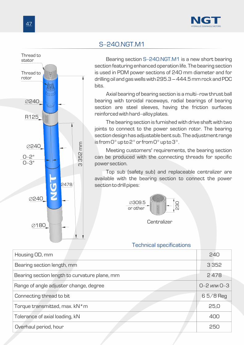
Bearing section is a new short bearing S-240.NGT.M1
section featuring enhanced operation life. The bearing section
is used in PDM power sections of 240 mm diameter and for
drilling oil and gas wells with 295.3 – 444.5 mm rock and PDC
bits.
Axial bearing of bearing section is a multi-row thrust ball
bearing with toroidal raceways, radial bearings of bearing
section are steel sleeves, having the friction surfaces
reinforced with hard-alloy plates.
The bearing section is furnished with drive shaft with two
joints to connect to the power section rotor. The bearing
section design has adjustable bent sub. The adjustment range
is from 0° up to 2° or from 0° up to 3°.
Meeting customers' requirements, the bearing section
can be produced with the connecting threads for specific
power section.
Top sub (safety sub) and replaceable centralizer are
available with the bearing section to connect the power
section to drill pipes:
240
3 352
0-2 èëè 0-3
2 478
6 5/8 Reg
25,0
400
250
S-240.NGT.M1
3 3
52
mm
R125
Ж240
Ж240
0-2°0-3°
Ж180
2478
Ж240
47HYDRAULIC DOWNHOLE MOTORS
Technical specifications
Housing OD, mm
Bearing section length, mm
Range of angle adjuster change, degree
Bearing section length to curvature plane, mm
Connecting thread to bit
Torque transmitted, max. kN*m
Tolerance of axial loading, kN
Overhaul period, hour
Thread torotor
Thread tostator
23
0
Centralizer
or other
Ж309.5

S-
24
0.N
GT
.M1
S-
17
8.N
GT
.M2
3
Bearing sections specification
Housing OD, mm
Bearing section length, mm
Range of angle adjusterchange, degree
Bearing section length tocurvature plane, mm
Connecting thread to bit
Torque transmitted, max. kN*m
Tolerance of axial loading, kN
Overhaul period, hour
76 9588 106
S-
10
6.N
GT
.M1
S-
10
6.N
GT
.M2
S-
12
0.N
GT
.M2
S-
17
8.N
GT
.M1
2S
-1
78
.NG
T.M
15
S-
17
8.N
GT
.M1
6
S-
19
5.N
GT
.M4
S-
21
0.N
GT
.M1
S-
16
5.N
GT
.M1
S-
76
.NG
T.M
2
S-
95
.NG
T.M
1
S-
88
.NG
T.M
1
106 120 178178 178 195 210165 240
1 227 1 5601 405 1 309 1 640 1 856 2 5462 546 2 587 2 546 2 7192 546 3 352
0-2 or 0-3
855 1 1391 025 883 1 214 1370 1 8561856 1 897 1 856 1 9871 856 2 478
2 3/8 Reg
2 3/8 Reg2 7/8 Reg
2 3/8 Reg
2 7/8 Reg
2 7/8 Reg
3 1/2 Reg
4 1/2 Reg
4 1/2 Reg
4 1/2 Reg
4 1/2 Reg
6 5/8 Reg
4 1/2 Reg
6 5/8 Reg
3,0 3,52,0 5,0 5,0 6,0 2424 24 27 2519 25
45 6555 80 80 100 250250 250 250 350200 400
200 200200 300 200 200 350280 280 250 250200 250
Bearing section code
48
HY
DR
AU
LIC
DO
WN
HO
LE
MO
TO
RS

The company provides full cycle of operations of the turbodrill production: designing, prototype production, stand and field tests, design improvement, commercial production of turbodrills.
Over the past 10 years close attention was paid to development and production of new turbine types, featuring high efficiency (efficiency of 60-70%). The turbines are produced by precision casting technique with investment pattern. Huge experience and knowledge accumulated by leading experts of the company have allowed using different methods of calculation while developing the turbine blade profiles and designing new turbines based on the experience accumulated and statistic data of the turbine model tests results.
Designing and production of a new turbine is the process requiring long period of time and significant expenses. Meeting clients' requirements, the company's specialists fulfill complete cycle of work regarding design and production of the turbine stages, starting from provision of the turbine blade profile for a mould production and finishing with the turbine stages production. The experience accumulated allows producing the turbines for the turbodrills having different speed characteristics from 350 to 2500 RPM for different bit types (cone, impregnated and PDC).
Today the company produces the turbines for 4 main standard sizes of the turbodrills - 127mm (4 3/4”), 178 mm (6 3/4“), 195 mm (7 11/16 “) and 240 mm (9 1/2”). All the turbine types (except 195 and 240 mm turbines) are produced of stainless steel. A new generation of the turbodrills has been designed based on these turbines. Most of them are presented in the catalogue.
One more achievement of NGT which is used in turbodrill designs is bearing section as damper with PDC axial bearings. Damping components are selected to reduce the intensity of vibrations from the bit during rock destruction. The bearing section and turbine radial bearings have support surfaces reinforced with hard alloy components.
Combination of the abovementioned design features and technological approaches being realized within the production of a new turbodrill generation provides high reliability and durability of all the main assemblies and members of the turbodrills at different conditions of operation: high temperatures, large range of chemical reagents used to support mud parameters required and effect of formation ingresses: H S; H SO ; H SO ; HCI; Cl . Warranty life of 2 2 3 2 4 2
the turbodrill till writing off reaches 900 hrs; overhaul period for the bearing sections with PDC axial bearing is 350 hrs and more (depending on dr i l l ing conditions).
Turbodrills
49HYDRAULIC DOWNHOLE MOTORS
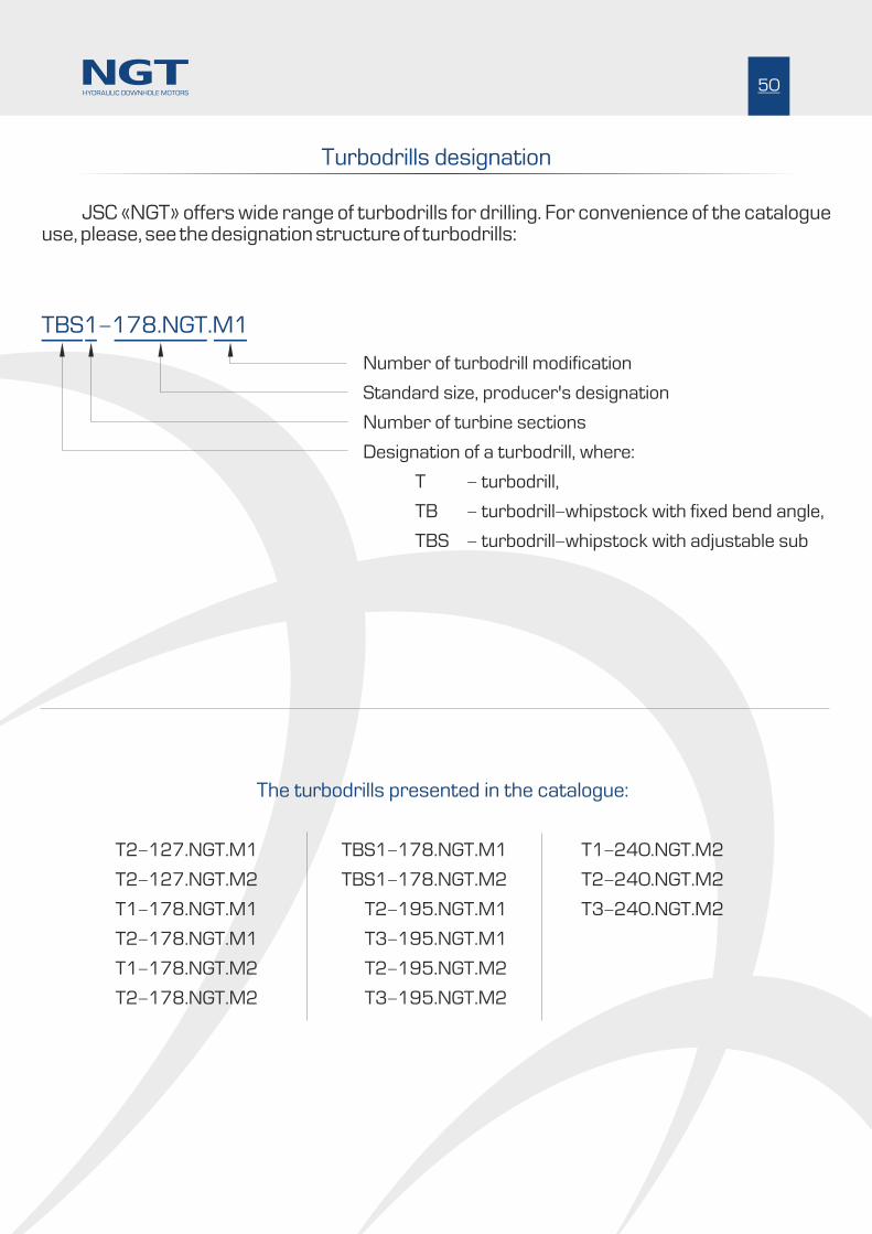
JSC «NGT» offers wide range of turbodrills for drilling. For convenience of the catalogue use, please, see the designation structure of turbodrills:
TBS1-178.NGT.M1
Number of turbodrill modification
Standard size, producer's designation
Number of turbine sections
Designation of a turbodrill, where:
Ò - turbodrill,
TB - turbodrill-whipstock with fixed bend angle,
TBS - turbodrill-whipstock with adjustable sub
The turbodrills presented in the catalogue:
T2-127.NGT.M1
T2-127.NGT.M2
T1-178.NGT.M1
T2-178.NGT.M1
T1-178.NGT.M2
T2-178.NGT.M2
TBS1-178.NGT.M1
TBS1-178.NGT.M2
T2-195.NGT.M1
T3-195.NGT.M1
T2-195.NGT.M2
T3-195.NGT.M2
T1-240.NGT.M2
T2-240.NGT.M2
T3-240.NGT.M2
Turbodrills designation
50HYDRAULIC DOWNHOLE MOTORS

T2-127.NGT.M1
Turbodrill has high speed of rotation and is used T2-127.NGT.M1
for drilling of wells with combination and impregnated bits of small
diameter.
The turbodrill contains two turbine sections and bearing section.
The turbine sections incorporate the turbine of high speed of rotation
and low pressure drop. The turbine efficiency constitutes 68-70% at
max. power. The turbodrill bearing section operates in mud and has axial
sliding bearing, the operating surfaces made out of synthetic diamond.
This allows reaching high power characteristics and overhaul operation
life (not less than 300 hours).
Housing OD, mm
OD of threaded connections, mm
Quantity of turbine sections, pc.
Turbodrill length, mm
Diameters of bits used, mm
Mud flow rate, l/sec
Connecting thread to drill pipes
Length of bearing section, mm
Length of bottom turbine section, mm
Length of top turbine section, mm
3Mud density, g/cm
Connecting thread to bit3
Max. density of mud, g/cm
Max. axial load, kN
Weight, kg
Max. temperature in well, °C
122
127
2
11 651
146,0-171,4
14-16
3 1/2 Reg
1 508
4 947
5 196
1,0
3 1/2 Reg
1,9
50
750
250
Turbodrill specification
Turbodrill power characteristic
Stall torque, N*m-1Speed of rotation at operating condition, min 1151-1316
1100-1450
Pressure drop, MPa 6,3-8,2
Max. power, kW 63-93
Bo
tto
m t
urb
ine
se
cti
on
4 9
47
mm
1 5
08
mm
Be
ari
ng
se
cti
on
5 1
96
mm
To
p t
urb
ine
se
cti
on
11
65
1 m
m
Ж122
Ж146-
Ж122
-162
Ж127
51HYDRAULIC DOWNHOLE MOTORS
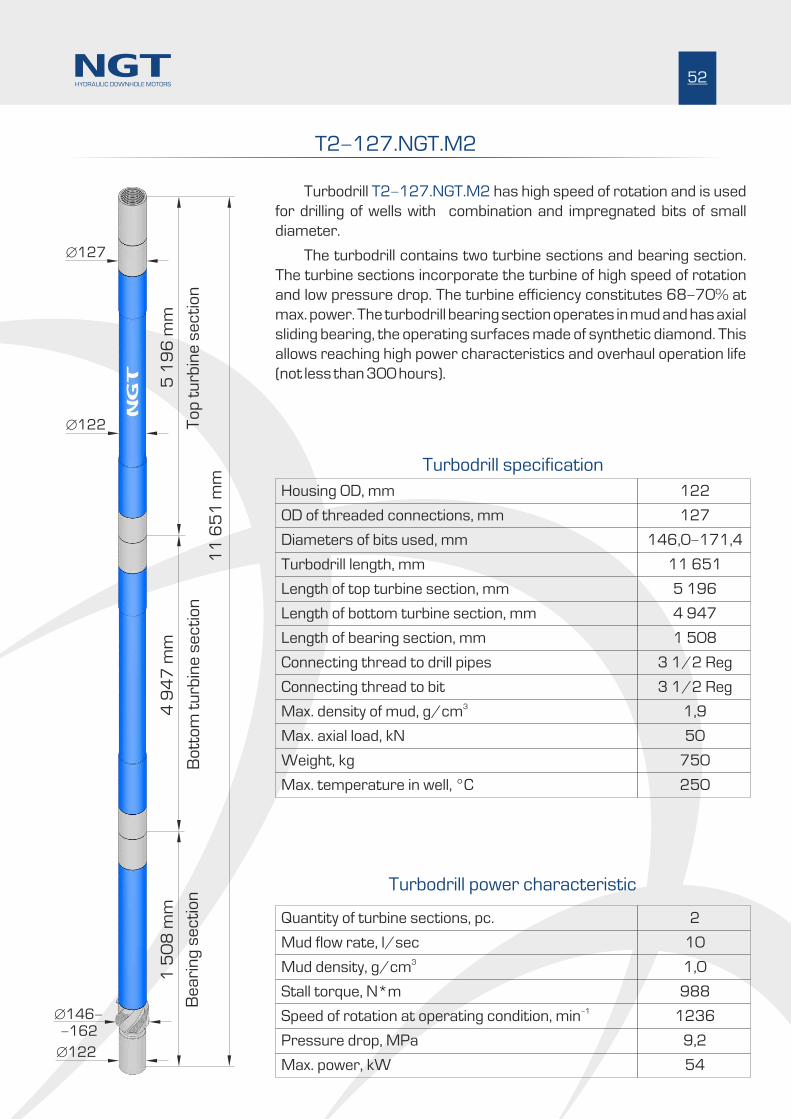
T2-127.NGT.M2
Turbodrill has high speed of rotation and is used T2-127.NGT.M2
for drilling of wells with combination and impregnated bits of small
diameter.
The turbodrill contains two turbine sections and bearing section.
The turbine sections incorporate the turbine of high speed of rotation
and low pressure drop. The turbine efficiency constitutes 68-70% at
max. power. The turbodrill bearing section operates in mud and has axial
sliding bearing, the operating surfaces made of synthetic diamond. This
allows reaching high power characteristics and overhaul operation life
(not less than 300 hours).
122
127
11 651
146,0-171,4
3 1/2 Reg
1 508
4 947
5 196
3 1/2 Reg
1,9
50
750
250
2
10
1,0
1236
988
9,2
54
52HYDRAULIC DOWNHOLE MOTORS
Housing OD, mm
OD of threaded connections, mm
Quantity of turbine sections, pc.
Turbodrill length, mm
Diameters of bits used, mm
Mud flow rate, l/sec
Connecting thread to drill pipes
Length of bearing section, mm
Length of bottom turbine section, mm
Length of top turbine section, mm
3Mud density, g/cm
Connecting thread to bit3
Max. density of mud, g/cm
Max. axial load, kN
Weight, kg
Max. temperature in well, °C
Stall torque, N*m-1Speed of rotation at operating condition, min
Pressure drop, MPa
Max. power, kW
Turbodrill specification
Turbodrill power characteristic
Bo
tto
m t
urb
ine
se
cti
on
4 9
47
mm
1 5
08
mm
Be
ari
ng
se
cti
on
5 1
96
mm
To
p t
urb
ine
se
cti
on
11
65
1 m
m
Ж122
Ж146-
Ж122
-162
Ж127

T1-178.NGT.M1 T2-178.NGT.M1 and
Turbodrill specification
Turbodrill power characteristic
High hydrodynamic alternating loads are created while tripping in a
well using 212,7-215,9 mm dia. bits and 195 mm dia. downhole motor due
to small annular distance between the well walls and the downhole motor.
This leads to reduction of the well wall stability, layer breakage, decrease of
well productivity. The turbodrills and of T1-178.NGT.M1 T2-178NGT.M1
178 mm OD are offered to increase the annular distance and, therefore, to
improve conditions of well drilling with 212,7-215,9 mm bits. The turbodrill
is available for drilling with impregnated and PDC bits.
The turbodrill incorporates one ( ) or two (T1-178.NGT.M1 T2-
178.NGT.M1) turbine sections and bearing section. High performance
turbine made out of stainless steel by precision casting method is used in the
turbine sections. The turbine efficiency constitutes 68-70% at max. power.
The turbodrill is completed with the bearing section of enhanced operation
life exceeding 400 hrs. The turbodrill bearing section operates in mud and
has axial sliding bearing, the operating surfaces made of synthetic diamond.
This allows reaching high power characteristics and increased overhaul life.
OD of threaded connections, mm
Code of turbodrill
Turbodrill length, mm
Diameters of bits used, mm
Connecting thread to drill pipes
Length of bearing section, mm
Length of bottom turbine section, mm
Length of top turbine section, mm
Connecting thread to bit3
Max. density of mud, g/cm
Max. axial load, kN
Weight, kg
Max. temperature in well, °C
T2-178.NGT.M1
178
T1-178.NGT.M1
13 0049 332
212,7-215,9
5 1/2 FH
2 0002 000
7 3327 332
3 672-
4 1/2 Reg
1,9
150
2 5002 100
250
Quantity of turbine sections, pc.
Mud flow rate, l/sec3Mud density, g/cm
21
25-32
1,0
32-36
1,0
Stall torque, N*m-1Speed of rotation at operating condition, min 646-827827-931
2450-40142843-3599
Pressure drop, MPa 5,0-8,25,8-7,4
Max. power, kW 72-151107-152
Bo
tto
m t
urb
ine
se
cti
on
7 3
32
mm
2 0
00
mm
Be
ari
ng
se
cti
on
3 6
72
mm
To
p t
urb
ine
se
cti
on
Ж178-
Ж152
Ж178
-214
Ж175
(on
ly in
)
Ò2
-1
78
.NG
T.M
1
53HYDRAULIC DOWNHOLE MOTORS
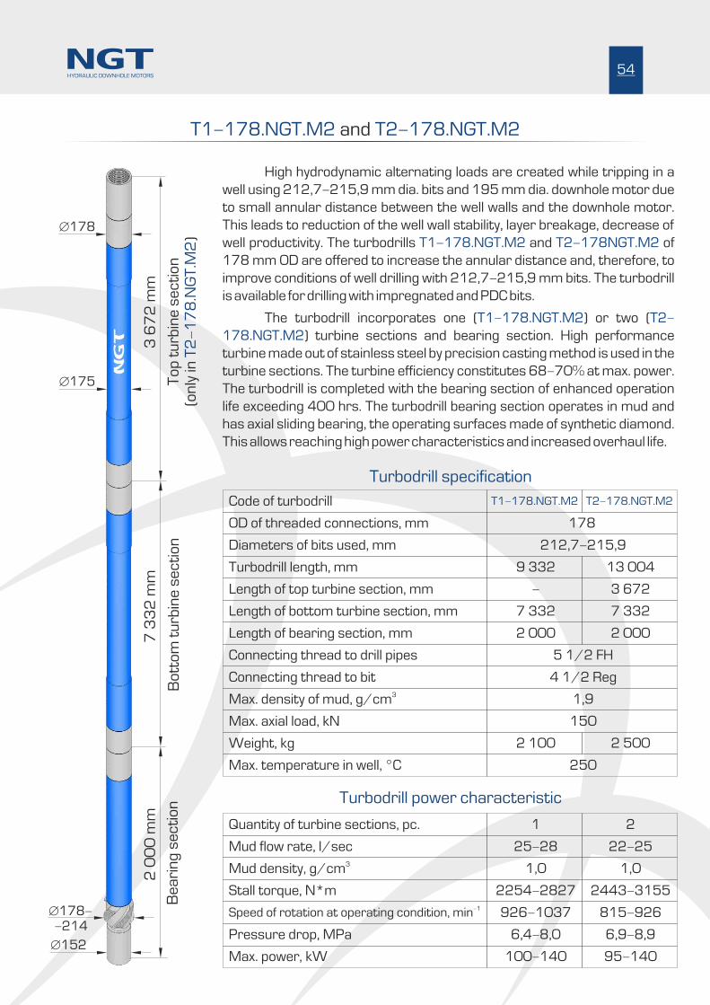
T1-178.NGT.M2 T2-178.NGT.M2 and
High hydrodynamic alternating loads are created while tripping in a
well using 212,7-215,9 mm dia. bits and 195 mm dia. downhole motor due
to small annular distance between the well walls and the downhole motor.
This leads to reduction of the well wall stability, layer breakage, decrease of
well productivity. The turbodrills and of T1-178.NGT.M2 T2-178NGT.M2
178 mm OD are offered to increase the annular distance and, therefore, to
improve conditions of well drilling with 212,7-215,9 mm bits. The turbodrill
is available for drilling with impregnated and PDC bits.
The turbodrill incorporates one ( ) or two (T1-178.NGT.M2 T2-
178.NGT.M2) turbine sections and bearing section. High performance
turbine made out of stainless steel by precision casting method is used in the
turbine sections. The turbine efficiency constitutes 68-70% at max. power.
The turbodrill is completed with the bearing section of enhanced operation
life exceeding 400 hrs. The turbodrill bearing section operates in mud and
has axial sliding bearing, the operating surfaces made of synthetic diamond.
This allows reaching high power characteristics and increased overhaul life.
T2-178.NGT.M2
178
T1-178.NGT.M2
13 0049 332
212,7-215,9
5 1/2 FH
2 0002 000
7 3327 332
3 672-
4 1/2 Reg
1,9
150
2 5002 100
250
21
22-25
1,0
25-28
1,0
815-926926-1037
2443-31552254-2827
6,9-8,96,4-8,0
95-140100-140
7 3
32
mm
2 0
00
mm
3 6
72
mm
To
p t
urb
ine
se
cti
on
Ж178-
Ж152
Ж178
-214
Ж175
(
)o
nly
inÒ
2-
17
8.N
GT
.M2
54HYDRAULIC DOWNHOLE MOTORS
OD of threaded connections, mm
Code of turbodrill
Turbodrill length, mm
Diameters of bits used, mm
Connecting thread to drill pipes
Length of bearing section, mm
Length of bottom turbine section, mm
Length of top turbine section, mm
Connecting thread to bit3
Max. density of mud, g/cm
Max. axial load, kN
Weight, kg
Max. temperature in well, °C
Quantity of turbine sections, pc.
Mud flow rate, l/sec3Mud density, g/cm
Stall torque, N*m-1Speed of rotation at operating condition, min
Pressure drop, MPa
Max. power, kW
Turbodrill specification
Turbodrill power characteristic
Bo
tto
m t
urb
ine
se
cti
on
Be
ari
ng
se
cti
on

TBS1-178.NGT.M1 TBS1-178.NGT.M2 and
Turbodrills and are new TBS1-178.NGT.M1 TBS1-178.NGT.M2
universal turbodrill-whipstocks with an ultra-short arm to the point of axes
curvature.
The turbodrill is available for drilling with impregnated and PDC bits in
212,7- 220,7 mm dia.
Turbodrill contains turbine section and bearing section as whipstock
with angle adjuster. Angle adjuster is available with the following bend angles
: 0°00', 0°13', 0°25', 0°37', 0°49', 1°00', 1°11', 1°20', 1°29', 1°37',
1°44', 1°50', 1°54', 2°00'. Flexible shaft of titanium alloy is used for torque
transmission.
Highly efficient turbines of M1 and M2 types are used in turbine
section of turbodrills. Both turbines are made of stainless steel by precision
casting method. The turbine efficiency constitutes 68-70% at max. power.
The turbodrill bearing sections have axial sliding bearing, the
operating surfaces made of synthetic diamond. This allows obtaining high
power characteristics and increased overhaul life.
Turbodrill specification
Turbodrill power characteristic
OD of threaded connections, mm
Code of turbodrill
Turbodrill length, mm
Diameters of bits used, mm
Connecting thread to drill pipes
Bearing section length to curvature plane, mm
Length of turbine section, mm
Connecting thread to bit3
Max. density of mud, g/cm
Max. axial load, kN
Weight, kg
Max. temperature in well, °C
TBS1-178.NGT.M2
178
TBS1-178.NGT.M1
10 96410 964
212,7-215,9
5 1/2 FH (NC-50)
1 4801 480
7 3327 332
4 1/2 Reg
1,9
150
2 1002 100
250
Quantity of turbine sections, pc.
Mud flow rate, l/sec3Mud density, g/cm
11
25-28
1,0
32-36
1,0
Stall torque, N*m-1Speed of rotation at operating condition, min 926-1037827-931
2254-28272843-3599
Pressure drop, MÐa 6,4-8,05,8-7,4
Max. power, kW 100-140107-152
Ж178
Ж178
7 3
32
mm
Tu
rbin
e s
ec
tio
n
10
96
4 m
m
3 3
04
mm
1 4
80
mm
up
to
a p
oin
t o
f a
cu
rva
ture
55HYDRAULIC DOWNHOLE MOTORS
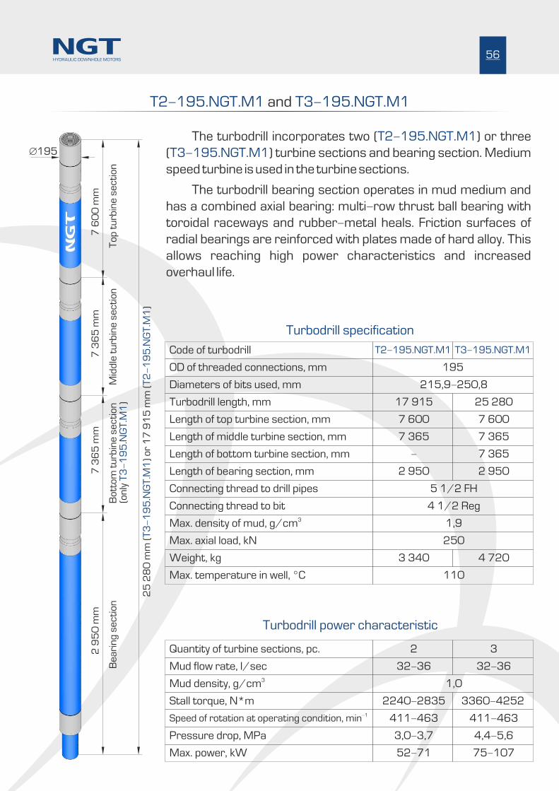
T2-195.NGT.M1 T3-195.NGT.M1 and
OD of threaded connections, mm
Code of turbodrill
Quantity of turbine sections, pc.
Turbodrill length, mm
Diameters of bits used, mm
Mud flow rate, l/sec
Connecting thread to drill pipes
Length of bearing section, mm
Length of bottom turbine section, mm
Length of top turbine section, mm
Length of middle turbine section, mm
3Mud density, g/cm
Connecting thread to bit3
Max. density of mud, g/cm
Max. axial load, kN
Weight, kg
Max. temperature in well, °C
T2-195.NGT.M1 T3-195.NGT.M1
195
2 3
17 915 25 280
215,9-250,8
32-36 32-36
5 1/2 FH
2 950 2 950
- 7 365
7 600 7 600
7 365 7 365
1,0
4 1/2 Reg
1,9
250
3 340 4 720
110
Turbodrill specification
Turbodrill power characteristic
Stall torque, N*m-1Speed of rotation at operating condition, min 411-463 411-463
2240-2835 3360-4252
Pressure drop, MÐa 3,0-3,7 4,4-5,6
Max. power, kW 52-71 75-107
The turbodrill incorporates two ( ) or three T2-195.NGT.M1
( ) turbine sections and bearing section. Medium T3-195.NGT.M1
speed turbine is used in the turbine sections.
The turbodrill bearing section operates in mud medium and
has a combined axial bearing: multi-row thrust ball bearing with
toroidal raceways and rubber-metal heals. Friction surfaces of
radial bearings are reinforced with plates made of hard alloy. This
allows reaching high power characteristics and increased
overhaul life.
7 3
65
mm
2 9
50
mm
7 6
00
mm
To
p t
urb
ine
se
cti
on
25
28
0 m
m (
.)
17
91
5
(.
)T
3-
19
5N
GT
.M1
T2
-1
95
NG
T.M
1o
rm
mЖ195
7 3
65
mm
Mid
dle
tu
rbin
e s
ec
tio
nB
ott
om
tu
rbin
e s
ec
tio
nB
ea
rin
g s
ec
tio
n(o
nly
.)
T3
-1
95
NG
T.M
1
56HYDRAULIC DOWNHOLE MOTORS

T2-195.NGT.M2 T3-195.NGT.M2and
T2-195.NGT.M2 T3-195.NGT.M2
195
2 3
17 915 25 280
215,9-250,8
32-36 32-36
5 1/2 FH
2 950 2 950
- 7 365
7 600 7 600
7 365 7 365
1,0
4 1/2 Reg
1,9
250
3 340 4 720
110
594-669 594-669
3151-3988 4726-5982
4,0-5,1 6,0-7,6
92-132 139-197
The turbodrill incorporates two ( ) or three (T2-195.NGT.M2 T3-
195.NGT.M2) turbine sections and bearing section. Highly productive
turbine made with precision casting technique is used in the turbine
sections.
The turbodrill bearing section operates in mud medium and has
a combined axial bearing: multi-row thrust ball bearing with toroidal
raceways and rubber-metal heals. Friction surfaces of radial bearings
are reinforced with plates made of hard alloy. This allows reaching
high power characteristics and increased overhaul life.
7 3
65
mm
2 9
50
mm
7 6
00
mm
25
28
0 m
m (
.)
17
91
5
(.
)T
3-
19
5N
GT
.M2
T2
-1
95
NG
T.M
2o
r m
m
Ж195
7 3
65
mm
(.
)o
nly
T3
-1
95
NG
T.M
2
57HYDRAULIC DOWNHOLE MOTORS
OD of threaded connections, mm
Code of turbodrill
Quantity of turbine sections, pc.
Turbodrill length, mm
Diameters of bits used, mm
Mud flow rate, l/sec
Connecting thread to drill pipes
Length of bearing section, mm
Length of bottom turbine section, mm
Length of top turbine section, mm
Length of middle turbine section, mm
3Mud density, g/cm
Connecting thread to bit3
Max. density of mud, g/cm
Max. axial load, kN
Weight, kg
Max. temperature in well, °C
Stall torque, N*m-1Speed of rotation at operating condition, min
Pressure drop, MÐa
Max. power, kW
Turbodrill power characteristic
Turbodrill specification
To
p t
urb
ine
se
cti
on
Mid
dle
tu
rbin
e s
ec
tio
nB
ott
om
tu
rbin
e s
ec
tio
nB
ea
rin
g s
ec
tio
n
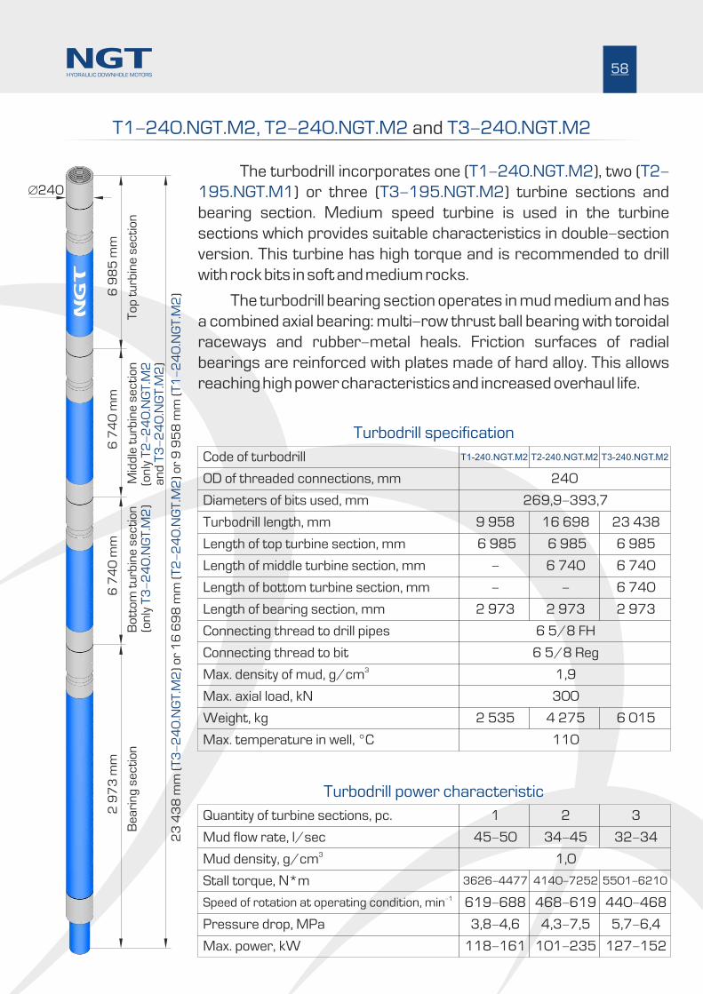
T1-240.NGT.M2, T2-240.NGT.M T3-240.NGT.M22 and
OD of threaded connections, mm
Code of turbodrill
Quantity of turbine sections, pc.
Turbodrill length, mm
Diameters of bits used, mm
Mud flow rate, l/sec
Connecting thread to drill pipes
Length of bearing section, mm
Length of bottom turbine section, mm
Length of top turbine section, mm
Length of middle turbine section, mm
3Mud density, g/cm
Connecting thread to bit3
Max. density of mud, g/cm
Max. axial load, kN
Weight, kg
Max. temperature in well, °C
T2-240.NGT.M2 T3-240.NGT.M2
240
T1-240.NGT.M2
2 31
16 698 23 4389 958
269,9-393,7
34-45 32-3445-50
6 5/8 FH
2 973 2 9732 973
- 6 740-
6 985 6 985
6 740 6 740
6 985
-
1,0
6 5/8 Reg
1,9
300
4 275 6 0152 535
110
Stall torque, N*m-1Speed of rotation at operating condition, min 468-619 440-468619-688
4140-7252 5501-62103626-4477
Pressure drop, MÐa 4,3-7,5 5,7-6,43,8-4,6
Max. power, kW 101-235 127-152118-161
The turbodrill incorporates one ( ), two (T1-240.NGT.M2 T2-
195.NGT.M1 T3-195.NGT.M2) or three ( ) turbine sections and
bearing section. Medium speed turbine is used in the turbine
sections which provides suitable characteristics in double-section
version. This turbine has high torque and is recommended to drill
with rock bits in soft and medium rocks.
The turbodrill bearing section operates in mud medium and has
a combined axial bearing: multi-row thrust ball bearing with toroidal
raceways and rubber-metal heals. Friction surfaces of radial
bearings are reinforced with plates made of hard alloy. This allows
reaching high power characteristics and increased overhaul life.
6 7
40
mm
2 9
73
mm
6 9
85
mm
To
p t
urb
ine
se
cti
on
23
43
8 m
m (
.)
16
69
8
()
9 9
58
(
)T
3-
24
0N
GT
.M2
T2
-2
40
.NG
T.M
2
T1
-2
40
.NG
T.M
2 o
r m
mo
rm
m
Ж240
6 7
40
mm
Mid
dle
tu
rbin
e s
ec
tio
nB
ott
om
tu
rbin
e s
ec
tio
nB
ea
rin
g s
ec
tio
n(
.
)o
nly
T3
-2
40
NG
T.M
2(
.o
nly
T2
-2
40
NG
T.M
2
)a
nd
T3
-2
40
.NG
T.M
2
58HYDRAULIC DOWNHOLE MOTORS
Turbodrill power characteristic
Turbodrill specification

T2-127.NGT.M1
Note: turbodrill power characteristics are given at mud density of 1.0 g/cm3
Length, mm
Quantity ofturbine
stages inturbodrill,
psc
Weight, kg
Speed ofrotation atoperatingcondition,
-1min
Stall torque,N*m
Pressuredrop,MPa to drill pipes
Max.power, kW
to bit
Dia. of bits used,mm
Quantity of turbine sections, pcs Connecting thread
Tu
rbin
e
Be
ari
ng
se
cti
on
11 651 750 2 1 220 -14-16 1151-1316 1100-1450 6,3-8,2 63-93 3 1/2 Reg 3 1/2 Reg146,0-171,4
Rage of bend
angles, deg
Mud flow rate, l/sec
Turbodrill specification
Code
T1-178.NGT.M1
T2-178.NGT.M1
T1-178.NGT.M2
TBS1-178.NGT.M1
T2-178.NGT.M2
TBS1-178.NGT.M2
T2-195.NGT.M1
T3-195.NGT.M1
T2-195.NGT.M2
T3-195.NGT.M2
T3-240.NGT.M2
T1-240.NGT.M2
T2-127.NGT.M2
9 332
11 651
13 004
9 332
10 964
13 004
10 964
17 915
25 280
17 915
25 280
2 100
750
2 500
2100
2100
2 500
2 100
3 340
4 720
3 340
4 720
1
2
2
1
1
2
1
2
3
2
3
1
1
1
1
1
1
1
1
1
1
1
170
220
240
150
170
210
150
220
330
220
330
-
-
32-36
10
-
-
0° - 2°
-
0° - 2°
-
-
-
-
25-32
25-28
32-36
22-25
25-28
32-36
32-36
32-36
32-36
827-931
1236
646-827
926-1037
827-931
815-926
926-1037
411-463
411-463
594-669
594-669
2843-3599
988
2450-4014
2254-2827
2843-3599
2443-3155
2254-2827
2240-2835
3360-4252
3151-3988
4726-5982
5,8-7,4
9,2
5,0-8,2
6,4-8,0
5.8-7.4
6,9-8,9
6.4-8.0
3,0-3,7
4,4-5,6
4,0-5,1
6,0-7,6
107-152
54
72-151
100-140
107-152
95-140
100-140
52-71
75-107
92-132
139-197
5 1/2 FH
3 1/2 Reg
5 1/2 FH
5 1/2 FH
5 1/2 FH
5 1/2 FH
5 1/2 FH
5 1/2 FH
5 1/2 FH
5 1/2 FH
5 1/2 FH
4 1/2 Reg
3 1/2 Reg
4 1/2 Reg
4 1/2 Reg
4 1/2 Reg
4 1/2 Reg
4 1/2 Reg
4 1/2 Reg
4 1/2 Reg
4 1/2 Reg
4 1/2 Reg
212,7-215,9
146,0-171,4
212,7-215,9
212,7-215,9
212,7-215,9
212,7-215,9
212,7-215,9
215,9-250,8
215,9-250,8
215,9-250,8
215,9-250,8
9 958
23 438
16 698
2 535
6 015
4 275
1
3
2
1
1
1
109
327
218
-45-50
-
-
32-34
34-45
619-688
440-468
468-619
3626-4477
5501-6210
4140-7252
3,8-4,6
5,7-6,4
4,3-7,5
118-161
127-152
101-235
6 5/8 FH
6 5/8 FH
6 5/8 FH
6 5/8 Reg
6 5/8 Reg
6 5/8 Reg
269,9-393,7
269,9-393,7
269,9-393,7T2-240.NGT.M2
HY
DR
AU
LIC
DO
WN
HO
LE
MO
TO
RS
59
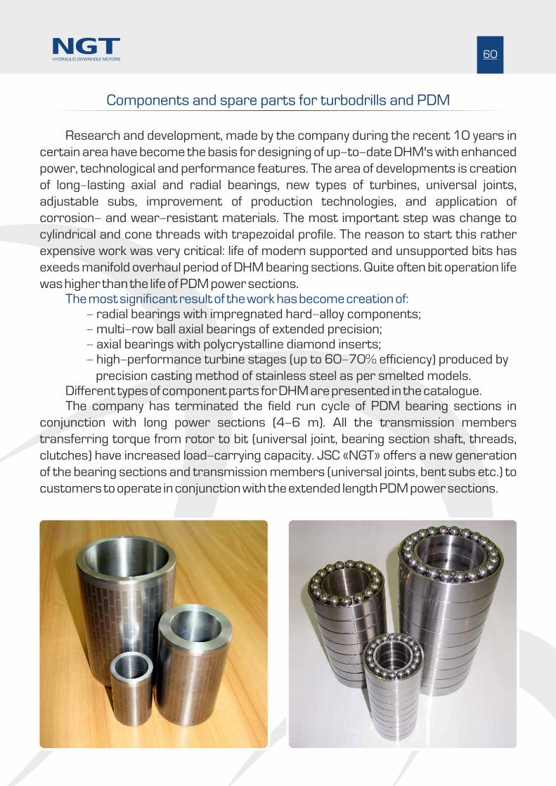
Research and development, made by the company during the recent 10 years in
certain area have become the basis for designing of up-to-date DHM's with enhanced
power, technological and performance features. The area of developments is creation
of long-lasting axial and radial bearings, new types of turbines, universal joints,
adjustable subs, improvement of production technologies, and application of
corrosion- and wear-resistant materials. The most important step was change to
cylindrical and cone threads with trapezoidal profile. The reason to start this rather
expensive work was very critical: life of modern supported and unsupported bits has
exeeds manifold overhaul period of DHM bearing sections. Quite often bit operation life
was higher than the life of PDM power sections.The most significant result of the work has become creation of:
- radial bearings with impregnated hard-alloy components;- multi-row ball axial bearings of extended precision;- axial bearings with polycrystalline diamond inserts;- high-performance turbine stages (up to 60-70% efficiency) produced by
precision casting method of stainless steel as per smelted models.Different types of component parts for DHM are presented in the catalogue. The company has terminated the field run cycle of PDM bearing sections in
conjunction with long power sections (4-6 m). All the transmission members
transferring torque from rotor to bit (universal joint, bearing section shaft, threads,
clutches) have increased load-carrying capacity. JSC «NGT» offers a new generation
of the bearing sections and transmission members (universal joints, bent subs etc.) to
customers to operate in conjunction with the extended length PDM power sections.
Components and spare parts for turbodrills and PDM
60HYDRAULIC DOWNHOLE MOTORS

JSC «NGT» has mastered production of hard alloy radial bearings using hard alloy plates of different configuration. Intervals between hard alloy plates are filled with wear-resistant material featuring much higher heat conductivity compared to the hard alloy. This excludes cracking of the hard alloy as the result of thermal shock at high radial loads or high sliding speeds.
See below different versions of friction surfaces of the radial bearings which differ by configuration of hard alloy plates, density of their location on friction surfaces, width of intervals between the plates which vary depending on operating conditions of the PDM or turbodrill run.
Hard alloy radial bearings
61HYDRAULIC DOWNHOLE MOTORS
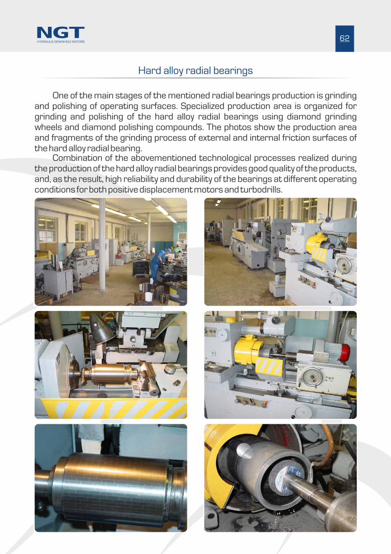
One of the main stages of the mentioned radial bearings production is grinding and polishing of operating surfaces. Specialized production area is organized for grinding and polishing of the hard alloy radial bearings using diamond grinding wheels and diamond polishing compounds. The photos show the production area and fragments of the grinding process of external and internal friction surfaces of the hard alloy radial bearing.
Combination of the abovementioned technological processes realized during the production of the hard alloy radial bearings provides good quality of the products, and, as the result, high reliability and durability of the bearings at different operating conditions for both positive displacement motors and turbodrills.
62HYDRAULIC DOWNHOLE MOTORS
Hard alloy radial bearings

The operating conditions of the radial bearing run are agreed beforehand:speed of rotation of the motor shaft , pressure drop across the bit, mud type ( drilling fluid), well configuration (deviation parameters), places of the bearing location in the motor bearing section ( at top, bottom). Materials, used while production of the composite hard alloy bearing are resistant to the temperature of up to 650°C and are compatible with all the chemical reagents such as water, oil, gas, salt, H S, H SO , H SO , HCl, Cl .2 2 3 2 4 2
Inner diameter 44 mm - 228 mm 25 mm - 460 mm
Outer diameter 51 mm - 242 mm 25 mm - 460 mm
Bearing diameter Bearing length
The hard alloy radial bearings for PDM's and turbodrills are produced in a wide range of sizes as per customers' drawings:
63HYDRAULIC DOWNHOLE MOTORS
Hard alloy radial bearings
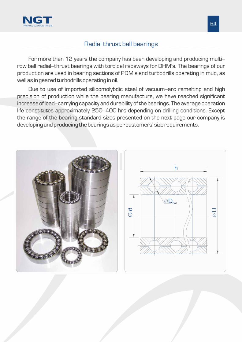
Radial thrust ball bearings
For more than 12 years the company has been developing and producing multi-
row ball radial-thrust bearings with toroidal raceways for DHM's. The bearings of our
production are used in bearing sections of PDM's and turbodrills operating in mud, as
well as in geared turbodrills operating in oil.
Due to use of imported silicomolybdic steel of vacuum-arc remelting and high
precision of production while the bearing manufacture, we have reached significant
increase of load-carrying capacity and durability of the bearings. The average operation
life constitutes approximately 250-400 hrs depending on drilling conditions. Except
the range of the bearing standard sizes presented on the next page our company is
developing and producing the bearings as per customers' size requirements.
Ж D
Ж d
h
Ж Dball
64HYDRAULIC DOWNHOLE MOTORS

90 152 385 10 20,638 499 30,5
92 148 550 16 19,050 614 37,5
65 128 352 10 19,050 390 22,2
60 100 315 13 12,700 256 8,4
50 88 350 13 12,700 234 11,5
Code d, mm D, mm h, mm N row D , mmball C , kNd M, kg
34
40
48
44
60
60
64,3
80
80
84
90
90
90
92
105
110
115
130
130
63
78
78
80
105
105
101,3
134
160
148
142
148
148
148
165
174
205
205
205
204
340
310
316
350
265
210
480
480
450
550
450
464
390
506
560
570
788
702
11
13
15
14
13
10
10
15
12
14
15
14
14
12
15
15
12
15
15
9,525
12,700
9,525
12,700
14,290
14,290
12,700
19,050
25,400
19,050
15,875
19,050
20,638
19,050
20,638
20,638
28,575
25,400
25,400
120
218
173
2,9
9,4
6,2
239 7,3
298
258
15,5
10,5
219 8,5
556 33,0
717 52,0
543 40,0
453 35,0
560 33,0
635
509
35,0
26,5
697 41,0
714 52,0
987 84,0
1 010
1010
106,0
93,0
Specification:
d N - inner diameter, mm - ball rows quantityrow
D D - outer diameter, mm - ball diameter, mm ball
h Ñ - length, mm -d dynamic load-carrying capacity, êN M - weight, kg
Note:
OM-718-11
OM-718-08
OM-713
OM-712-02
OM-710-01
OM-708
OM-708-01
OM-708-02
OM-709-01
OM-712-01
OM-712-05
OM-713-01
OM-716-01
OM-716-02
OM-717-01
OM-718
OM-718-01
OM-718-05
OM-718-10
OM-721
OM-722
OM-723
OM-726
OM-726-01
65HYDRAULIC DOWNHOLE MOTORS
Radial thrust ball bearings
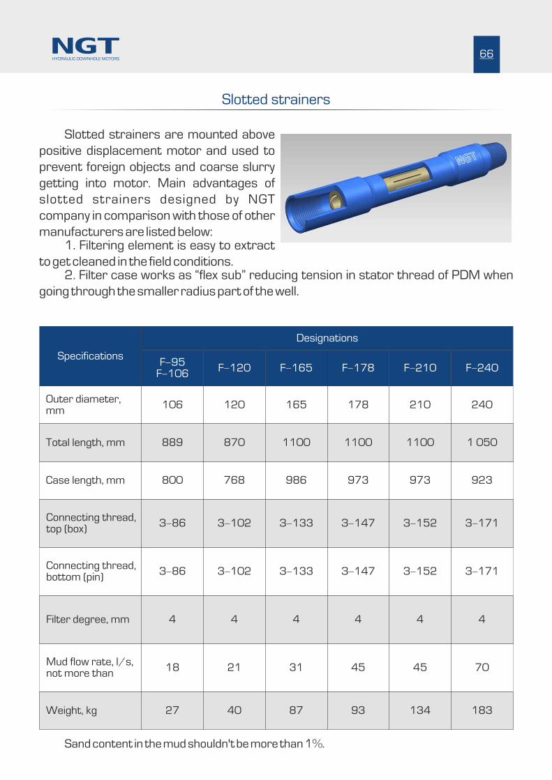
Slotted strainers
66
Connecting thread, top (box)
Filter degree, mm
Weight, kg
Total length, mm
Slotted strainers are mounted above
positive displacement motor and used to
prevent foreign objects and coarse slurry
getting into motor. Main advantages of
slotted strainers designed by NGT
company in comparison with those of other
manufacturers are listed below:1. Filtering element is easy to extract
to get cleaned in the field conditions.2. Filter case works as “flex sub” reducing tension in stator thread of PDM when
going through the smaller radius part of the well.
870
Ç-102
21
4
1100
Ç-133
31
4
1100 1100 1 050
Ç-147 Ç-152
45 45 70
4 4 4
Specifications
Designations
F-95F-106
F-120 F-165 F-178 F-210 F-240
889
Ç-86
18
4
106
800
Ç-86
27
120
768
Ç-102
40
165
986
Ç-133
87
178 210 240
973 973 923
Ç-147 Ç-152 Ç-171
93 134 183
Outer diameter, mm
Mud flow rate, l/s, not more than
Case length, mm
Connecting thread, bottom (pin)
Ç-171
Sand content in the mud shouldn't be more than 1%.
HYDRAULIC DOWNHOLE MOTORS
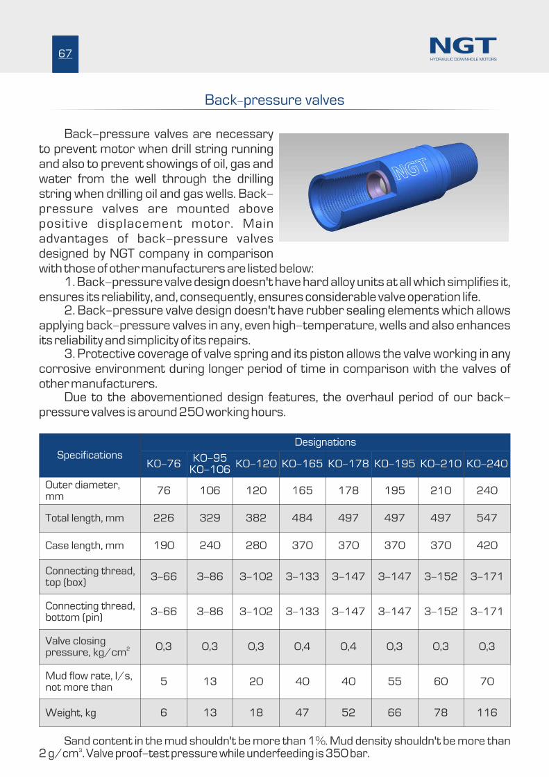
Connecting thread, top (box)
Valve closing 2pressure, kg/cm
Weight, kg
Total length, mm
Back-pressure valves
Back-pressure valves are necessary to prevent motor when drill string running and also to prevent showings of oil, gas and water from the well through the drilling string when drilling oil and gas wells. Back-pressure valves are mounted above positive displacement motor. Main advantages of back-pressure valves designed by NGT company in comparison with those of other manufacturers are listed below:
1. Back-pressure valve design doesn't have hard alloy units at all which simplifies it, ensures its reliability, and, consequently, ensures considerable valve operation life.
2. Back-pressure valve design doesn't have rubber sealing elements which allows applying back-pressure valves in any, even high-temperature, wells and also enhances its reliability and simplicity of its repairs.
3. Protective coverage of valve spring and its piston allows the valve working in any corrosive environment during longer period of time in comparison with the valves of other manufacturers.
Due to the abovementioned design features, the overhaul period of our back-pressure valves is around 250 working hours.
329
Ç-86
13
0,3
382
Ç-102
20
0,3
484 497 497 497 547
Ç-133 Ç-147
40 40 55 60 70
0,4 0,4 0,3 0,3 0,3
Specifications
Designations
KO-76KO-95
KO-106KO-120 KO-165 KO-178 KO-195 KO-210 KO-240
226
Ç-66
5
0,3
76
190
Ç-66
6
106
240
Ç-86
13
120
280
Ç-102
18
165 178 195 210 240
370 370 370 370 420
Ç-133 Ç-147 Ç-147 Ç-152 Ç-171
47 52 66 78 116
Outer diameter, mm
Mud flow rate, l/s, not more than
Case length, mm
Connecting thread, bottom (pin)
Ç-147 Ç-152 Ç-171
67
Sand content in the mud shouldn't be more than 1%. Mud density shouldn't be more than 32 g/cm . Valve proof-test pressure while underfeeding is 350 bar.
HYDRAULIC DOWNHOLE MOTORS
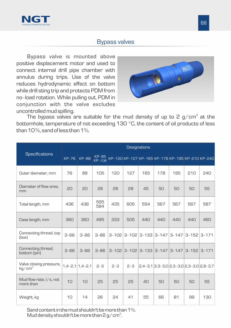
Bypass valves
Bypass valve is mounted above
positive displacement motor and used to
connect internal drill pipe chamber with
annulus during trips. Use of the valve
reduces hydrodynamic effect on bottom
while drill sting trip and protects PDM from
no-load rotation. While pulling out, PDM in
conjunction with the valve excludes
uncontrolled mud spilling.3
The bypass valves are suitable for the mud density of up to 2 g/cm at the
bottomhole, temperature of not exceeding 130 °C, the content of oil products of less
than 10 %, sand of less than 1%.
20 50
360 440
1,4-2,1 2,3-3,0
Ç-66 Ç-147
14 66
28 50
495 440
2-3 2,3-3,0
Ç-86 Ç-147
26 81
28 5028 5545
333 440505 460
2-3 2,3-3,02-3 2,8-3,72,4-3,1
Ç-102 Ç-1523-102 Ç-171Ç-133
24 9941 13055
Specifications
Designations
KP-76 KP-88 KP-178KP-95KP-106
KP-195KP-120 KP-210KP-127 KP-240KP-165
20
360
1,4-2,1
Ç-66
10
76
436
Ç-66
10
88 178
436 567
Ç-66 Ç-147
10 50
105 195
595584
567
Ç-86 Ç-147
25 50
120 210127 240165
435 567605 587554
Ç-102 Ç-1523-102 Ç-171Ç-133
25 5025 5540
Diameter of flow area, mm
Case length, mm
Connecting thread, bottom (pin)
Mud flow rate, l/s, not more than
Outer diameter, mm
Valve closing pressure, 2kg/cm
Weight, kg
Total length, mm
Connecting thread, top (box)
440
68
Sand content in the mud shouldn't be more than 1%.3
Mud density shouldn't be more than 2 g/cm .
HYDRAULIC DOWNHOLE MOTORS

Centralizers
Centralizers are used as components of bottom hole drill string assembly when
drilling oil and gas wells.
Application
The centralizers are used for:
- holding vertical borehole section when drilling vertical wells;
- steering parameters of well deviation and its stabilization.
Production versions
Meeting customer's requirements different centralizer versions are available:
- 98,4 - 311 mm diameter;
- straight blades;
- spiral blades;
- different lengths;
- different threads as per GOST P50864-96 or API Specs 7.
The centralizer housings are produced out of steel 40XH2MA. Operating surfaces
of the blades and lead-in chamfers are reinforced with teeth made out of hard alloy VK6
or VK8.
69HYDRAULIC DOWNHOLE MOTORS
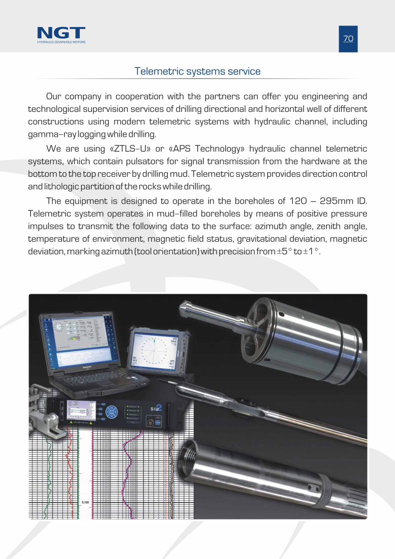
Telemetric systems service
Our company in cooperation with the partners can offer you engineering and
technological supervision services of drilling directional and horizontal well of different
constructions using modern telemetric systems with hydraulic channel, including
gamma-ray logging while drilling.
We are using «ZTLS-U» or «APS Technology» hydraulic channel telemetric
systems, which contain pulsators for signal transmission from the hardware at the
bottom to the top receiver by drilling mud. Telemetric system provides direction control
and lithologic partition of the rocks while drilling.
The equipment is designed to operate in the boreholes of 120 – 295mm ID.
Telemetric system operates in mud-filled boreholes by means of positive pressure
impulses to transmit the following data to the surface: azimuth angle, zenith angle,
temperature of environment, magnetic field status, gravitational deviation, magnetic
deviation, marking azimuth (tool orientation) with precision from ±5° to ±1°.
70HYDRAULIC DOWNHOLE MOTORS

Bit service
JSC «NGT» and partners can offer you bit services including development of the bit
program, delivery of the bits, and engineer support of the drilling process. Close
cooperation with bits producers allows our company to use the whole range of bits: from
classic rock bits to modern PDC bits and high-speed impregnated bits. Field engineers
are trained special manufacturer education programs and get all skills and knowledge
needed to service bits properly and effectively. Great experience gained in working with DHM allows us to provide optimal
matching of Bit-DHM set at the development stage of project. Besides, provision of the
complex Bit-DHM service leads to our full responsibility for this most important
components of DHM as to it reliability & rate of penetration and high cost efficiency as a
whole.
71HYDRAULIC DOWNHOLE MOTORS
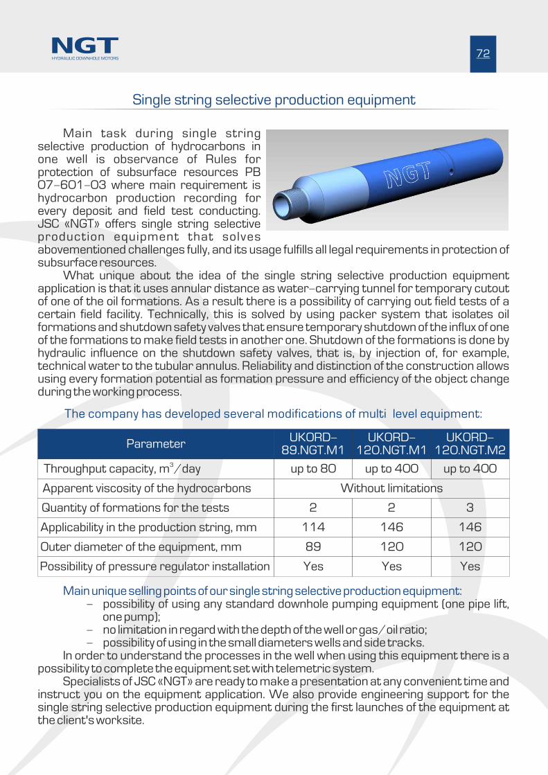
Single string selective production equipment
Main task during single string selective production of hydrocarbons in one well is observance of Rules for protection of subsurface resources PB 07-601-03 where main requirement is hydrocarbon production recording for every deposit and field test conducting. JSC «NGT» offers single string selective production equipment that solves abovementioned challenges fully, and its usage fulfills all legal requirements in protection of subsurface resources.
What unique about the idea of the single string selective production equipment application is that it uses annular distance as water-carrying tunnel for temporary cutout of one of the oil formations. As a result there is a possibility of carrying out field tests of a certain field facility. Technically, this is solved by using packer system that isolates oil formations and shutdown safety valves that ensure temporary shutdown of the influx of one of the formations to make field tests in another one. Shutdown of the formations is done by hydraulic influence on the shutdown safety valves, that is, by injection of, for example, technical water to the tubular annulus. Reliability and distinction of the construction allows using every formation potential as formation pressure and efficiency of the object change during the working process.
HYDRAULIC DOWNHOLE MOTORS72
The company has developed several modifications of multi�level equipment:
Main unique selling points of our single string selective production equipment: - possibility of using any standard downhole pumping equipment (one pipe lift,
one pump);- no limitation in regard with the depth of the well or gas/oil ratio; - possibility of using in the small diameters wells and side tracks.
In order to understand the processes in the well when using this equipment there is a possibility to complete the equipment set with telemetric system.
Specialists of JSC «NGT» are ready to make a presentation at any convenient time and instruct you on the equipment application. We also provide engineering support for the single string selective production equipment during the first launches of the equipment at the client's worksite.
Apparent viscosity of the hydrocarbons
Applicability in the production string, mm
Possibility of pressure regulator installation
Without limitations
114 146
Yes Yes Yes
ParameterUKORD-
89.NGT.M1UKORD-
120.NGT.M1UKORD-
120.NGT.M23
Throughput capacity, m /day
Quantity of formations for the tests
Outer diameter of the equipment, mm
up to 80 up to 400 up to 400
2 2 3
89 120 120
146

JSC «NGT»54, Fominskaya str., Perm, Russia
+007 (342) 238-61-01
+007 (342) 238-61-02
www.turbodrill.com
Address:
Phone:
Fax:
E-mail:
Web: