Embed Size (px)
Citation preview
Gas Well De-Liquification Workshop
Denver, Colorado
February 27 – March1, 2006
Downhole Gas SeparatorsA Laboratory and Field Study
Jim McCoy, Echometer CompanyTony Podio, University of Texas at AustinLynn Rowlan, Echometer CompanyResearch Funds Provided by Echometer, ConocoPhillips, & Yates Petroleum
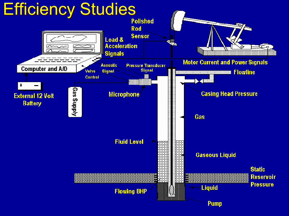
Efficiency StudiesEfficiency Studies
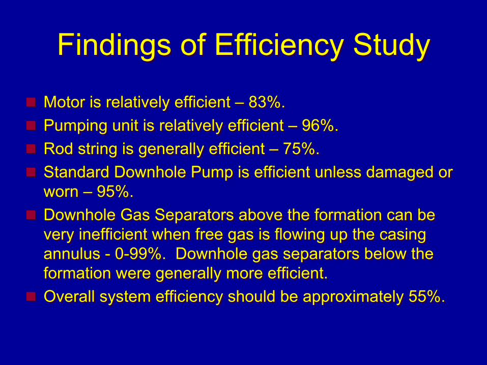
Findings of Efficiency StudyFindings of Efficiency Study
Motor is relatively efficient – 83%.Pumping unit is relatively efficient – 96%.Rod string is generally efficient – 75%.Standard Downhole Pump is efficient unless damaged or worn – 95%.Downhole Gas Separators above the formation can be very inefficient when free gas is flowing up the casing annulus - 0-99%. Downhole gas separators below the formation were generally more efficient.Overall system efficiency should be approximately 55%.
Motor is relatively efficient – 83%.Pumping unit is relatively efficient – 96%.Rod string is generally efficient – 75%.Standard Downhole Pump is efficient unless damaged or worn – 95%.Downhole Gas Separators above the formation can be very inefficient when free gas is flowing up the casing annulus - 0-99%. Downhole gas separators below the formation were generally more efficient.Overall system efficiency should be approximately 55%.
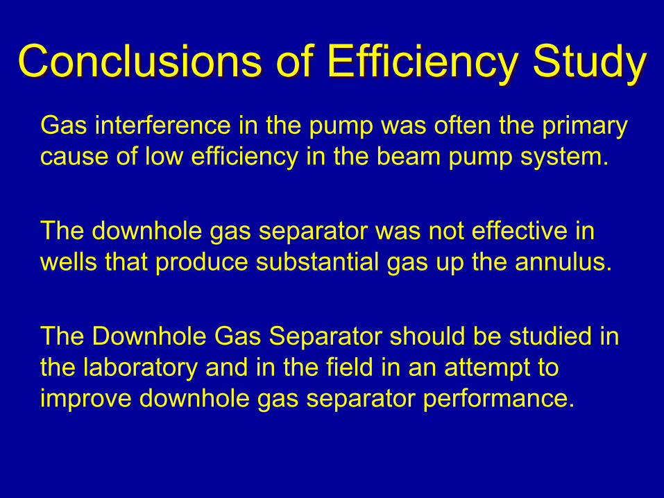
Conclusions of Efficiency StudyConclusions of Efficiency StudyGas interference in the pump was often the primary cause of low efficiency in the beam pump system.
The downhole gas separator was not effective in wells that produce substantial gas up the annulus.
The Downhole Gas Separator should be studied in the laboratory and in the field in an attempt to improve downhole gas separator performance.
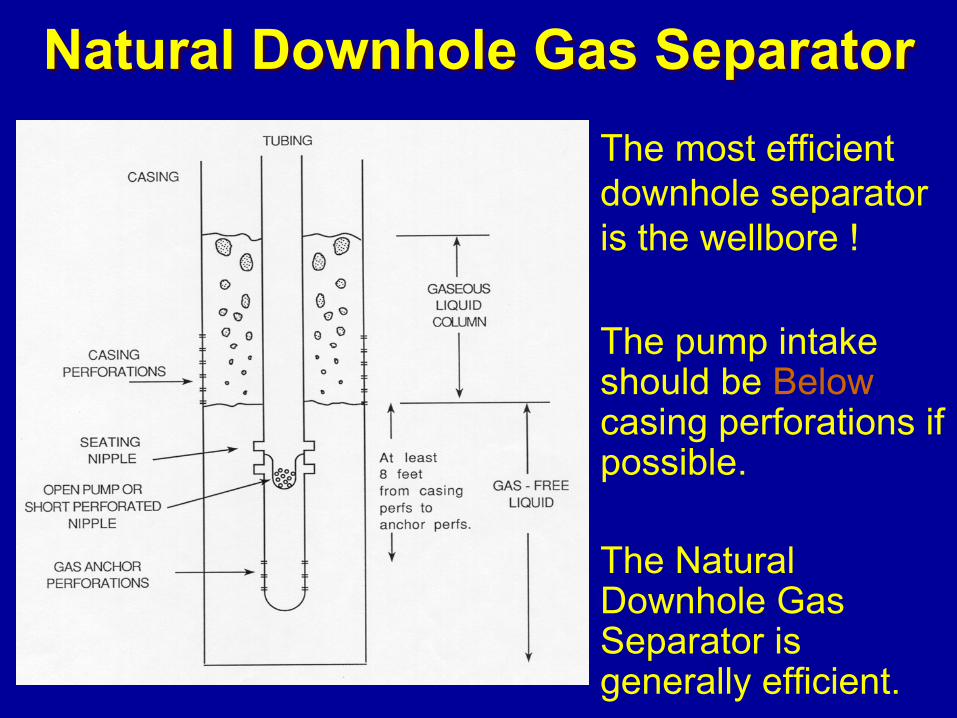
Natural Downhole Gas SeparatorNatural Downhole Gas SeparatorThe most efficient downhole separator is the wellbore !
The pump intake should be Belowcasing perforations if possible.
The Natural Downhole Gas Separator is generally efficient.
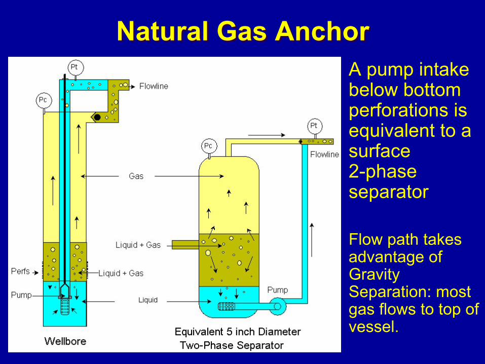
Natural Gas AnchorNatural Gas AnchorA pump intake below bottom perforations is equivalent to a surface2-phase separator
Flow path takes advantage of Gravity Separation: most gas flows to top of vessel.
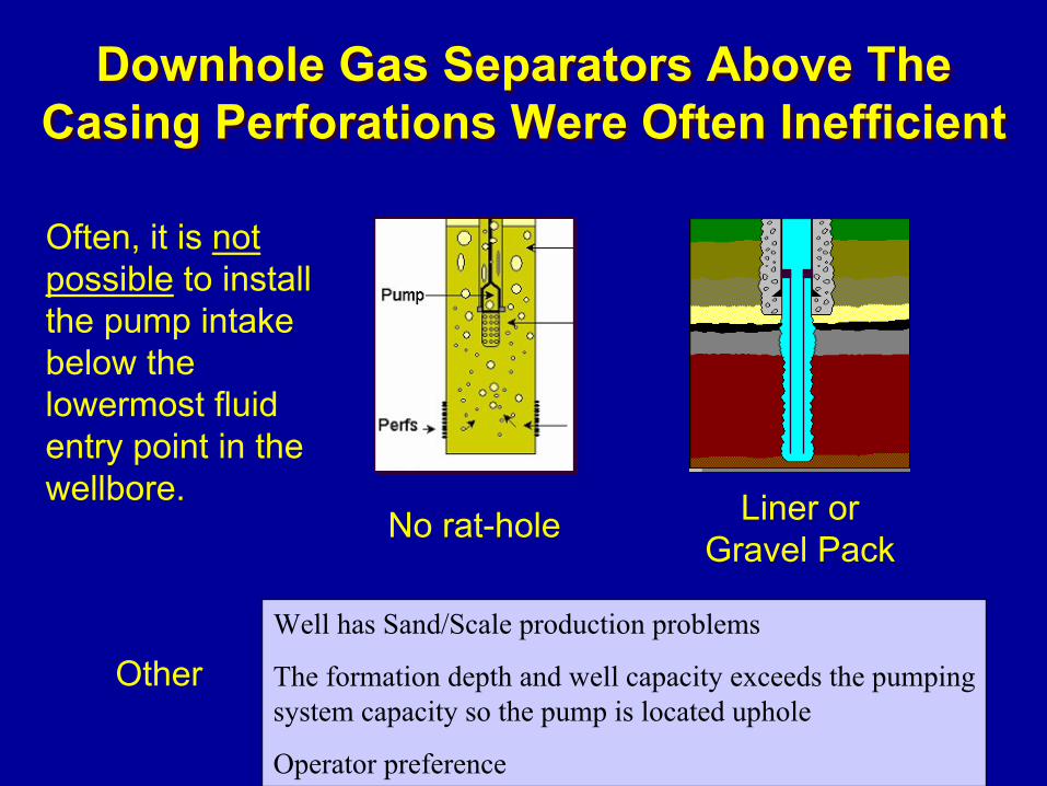
Downhole Gas Separators Above The Casing Perforations Were Often Inefficient
Downhole Gas Separators Above The Casing Perforations Were Often Inefficient
No rat-hole Liner or Gravel Pack
Well has Sand/Scale production problems
The formation depth and well capacity exceeds the pumping system capacity so the pump is located uphole
Operator preference
Other
Often, it is not possible to install the pump intake below the lowermost fluid entry point in the wellbore.
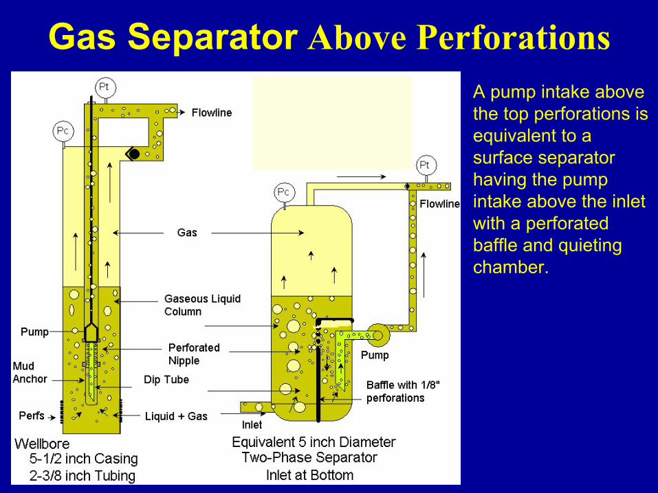
Gas Separator Above PerforationsA pump intake above the top perforations is equivalent to a surface separator having the pump intake above the inlet with a perforated baffle and quieting chamber.
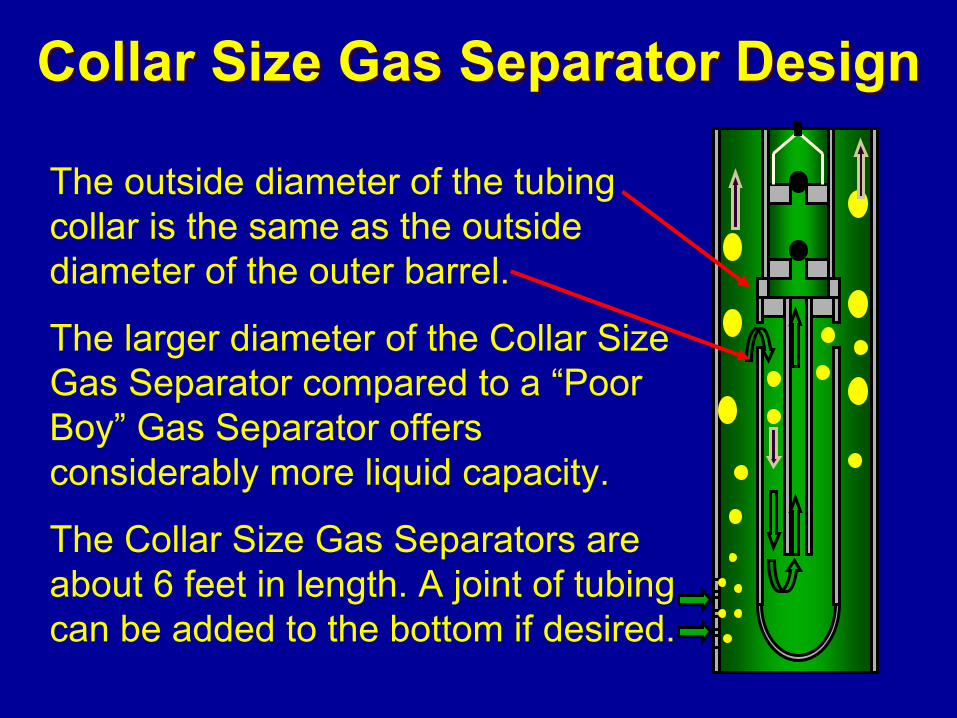
Collar Size Gas Separator DesignCollar Size Gas Separator Design
The outside diameter of the tubing collar is the same as the outside diameter of the outer barrel.
The larger diameter of the Collar Size Gas Separator compared to a “Poor Boy” Gas Separator offers considerably more liquid capacity.
The Collar Size Gas Separators are about 6 feet in length. A joint of tubing can be added to the bottom if desired.
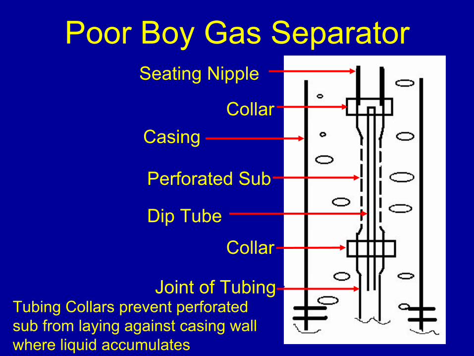
Poor Boy Gas SeparatorSeating Nipple
Collar
Perforated Sub
Collar
Joint of Tubing
Dip Tube
Tubing Collars prevent perforated sub from laying against casing wall where liquid accumulates
Casing
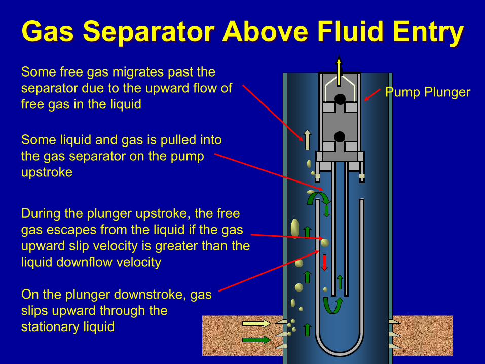
Gas Separator Above Fluid EntryGas Separator Above Fluid EntrySome free gas migrates past the separator due to the upward flow of free gas in the liquid
During the plunger upstroke, the free gas escapes from the liquid if the gas upward slip velocity is greater than the liquid downflow velocity
Some liquid and gas is pulled into the gas separator on the pump upstroke
On the plunger downstroke, gas slips upward through the stationary liquid
Pump Plunger
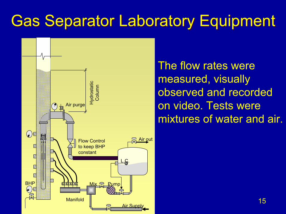
Gas Separator Laboratory EquipmentGas Separator Laboratory Equipment
BHP
Air purge Hyd
rost
atic
Col
umn
Flow Controlto keep BHPconstant
Air Supply
Air out
Manifold
Mix Pump
L.C.
The flow rates were measured, visually observed and recorded on video. Tests were mixtures of water and air.
15
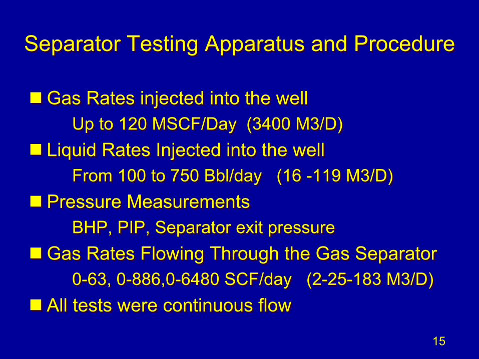
Separator Testing Apparatus and ProcedureSeparator Testing Apparatus and Procedure
Gas Rates injected into the wellUp to 120 MSCF/Day (3400 M3/D)
Liquid Rates Injected into the wellFrom 100 to 750 Bbl/day (16 -119 M3/D)
Pressure MeasurementsBHP, PIP, Separator exit pressure
Gas Rates Flowing Through the Gas Separator0-63, 0-886,0-6480 SCF/day (2-25-183 M3/D)
All tests were continuous flow
15
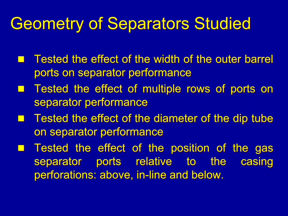
Geometry of Separators StudiedGeometry of Separators Studied
Tested the effect of the width of the outer barrel ports on separator performanceTested the effect of multiple rows of ports on separator performanceTested the effect of the diameter of the dip tube on separator performanceTested the effect of the position of the gas separator ports relative to the casing perforations: above, in-line and below.
Tested the effect of the width of the outer barrel ports on separator performanceTested the effect of multiple rows of ports on separator performanceTested the effect of the diameter of the dip tube on separator performanceTested the effect of the position of the gas separator ports relative to the casing perforations: above, in-line and below.
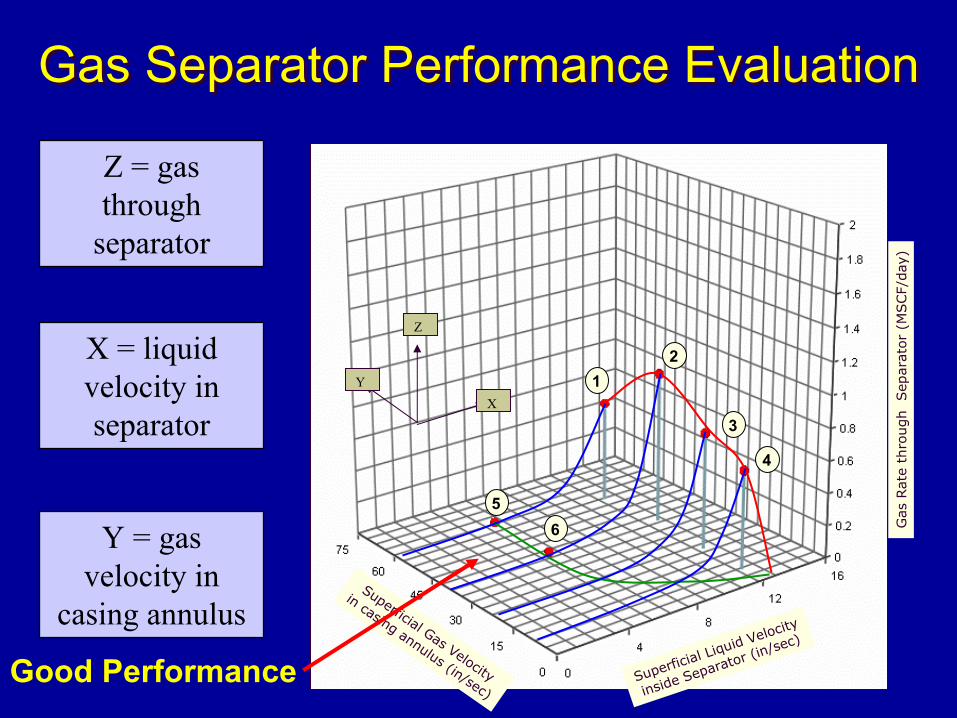
Gas Separator Performance EvaluationGas Separator Performance Evaluation
Superficial Liquid Velocity
inside Separator (in/sec)
Superficial Gas Velocity
in casing annulus (in/sec)
Gas
Rat
e th
rough
Sep
arat
or
(MSCF/
day
)
1
65
2
3
4
X
Z
Y
Z = gas through
separator
X = liquid velocity in separator
Y = gas velocity in
casing annulus
Good Performance
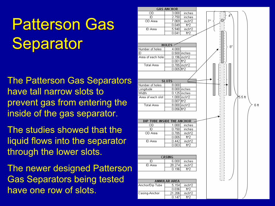
Patterson Gas SeparatorPatterson Gas Separator
The Patterson Gas Separators have tall narrow slots to prevent gas from entering the inside of the gas separator.
The studies showed that the liquid flows into the separator through the lower slots.
The newer designed Patterson Gas Separators being tested have one row of slots.
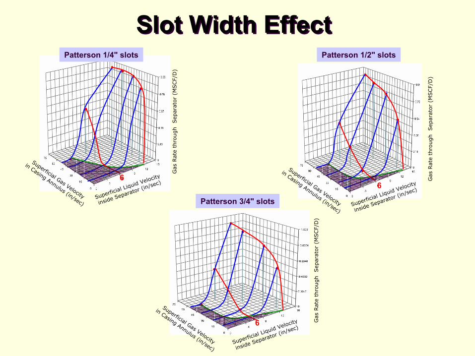
Slot Width EffectSlot Width Effect
Superficial Liquid Velocity
inside Separator (in/sec)
Superficial Gas Velocity
in Casing Annulus (in/sec)
Gas
Rat
e th
rough
Sep
arat
or
(MSC
F/D
)6
Superficial Liquid Velocity
inside Separator (in/sec)
Superficial Gas Velocity
in Casing Annulus (in/sec)
Gas
Rat
e th
rough
Sep
arat
or
(MSC
F/D
)
6
Superficial Liquid Velocity
inside Separator (in/sec)
Superficial Gas Velocity
in Casing Annulus (in/sec)
Gas
Rat
e th
rough
Sep
arat
or
(MSC
F/D
)6
Patterson 1/4" slots Patterson 1/2" slots
Patterson 3/4" slots
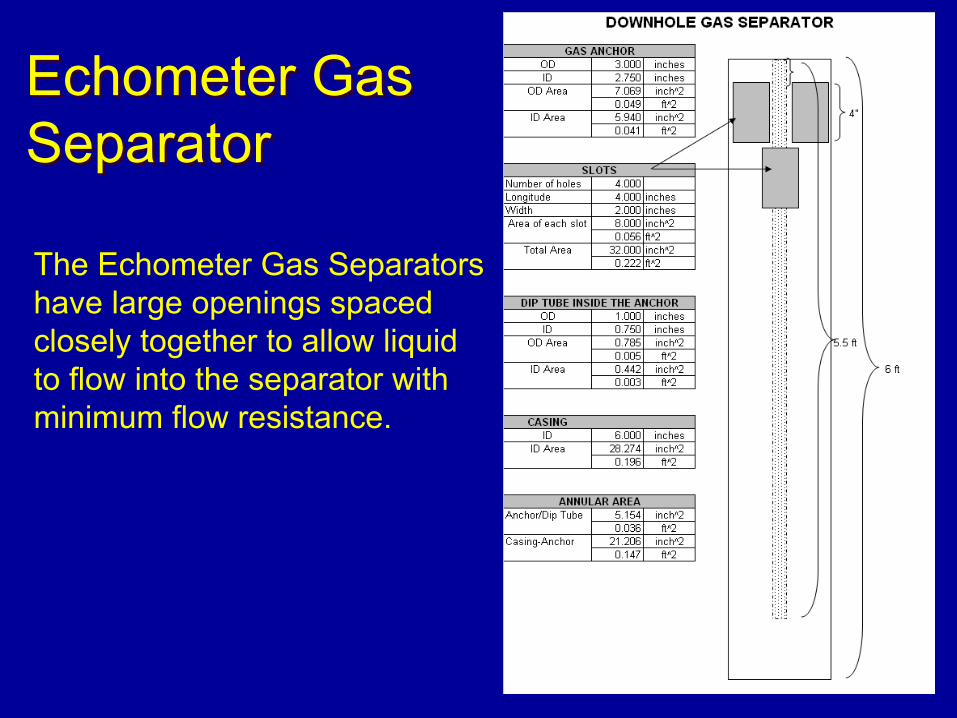
Echometer Gas SeparatorEchometer Gas Separator
The Echometer Gas Separators have large openings spaced closely together to allow liquid to flow into the separator with minimum flow resistance.
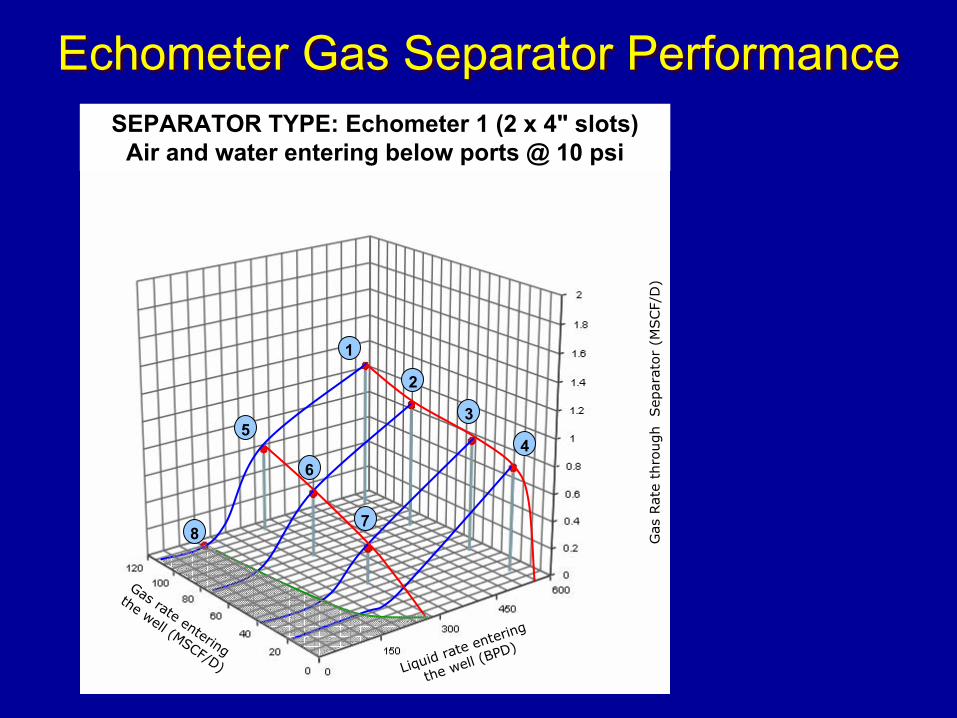
Echometer Gas Separator PerformanceEchometer Gas Separator Performance
Liquid rate entering
the well (BPD)
Gas rate entering
the well (MSCF/D)G
as R
ate
thro
ugh
Sep
arat
or
(MSCF/
D)
1
2
3
45
6
78
SEPARATOR TYPE: Echometer 1 (2 x 4" slots) Air and water entering below ports @ 10 psi
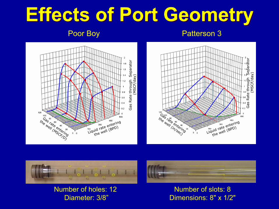
Effects of Port GeometryEffects of Port Geometry
Liquid rate entering
the well (BPD)
Gas rate entering
the well (MSCF/D)
Gas
Rat
e th
rough Sep
arat
or
(MSCF/
day
)Liquid rate entering
the well (BPD)
Gas rate entering
the well (in/sec)
Gas
Rat
e th
rough Sep
arat
or
(MSCF/
day
)
Poor Boy Patterson 3
Number of holes: 12Diameter: 3/8”
Number of slots: 8Dimensions: 8" x 1/2"
Additional Data in Paper
Additional laboratory data is presented in the paper. Time restraints do not permit showing all of the laboratory tests.
10

Field Applications
10
Collar Size Gas Separator Field TestsVs.
“Poor Boy” Gas Separator
Collar Size Gas Separator Field TestsVs.
“Poor Boy” Gas Separator
Vogt 8A - Improvement over “Poor Boy”
Coalbed Methane Well - Improvement
Jones 1- No Improvement over “Poor Boy”
Vogt 8A - Improvement over “Poor Boy”
Coalbed Methane Well - Improvement
Jones 1- No Improvement over “Poor Boy”
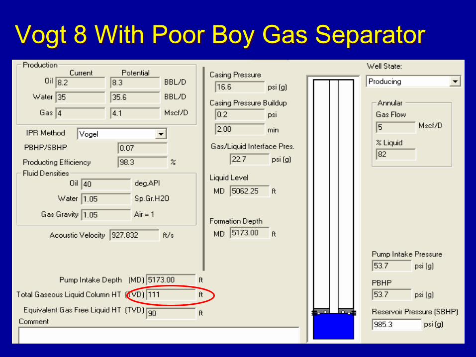
Vogt 8 With Poor Boy Gas SeparatorVogt 8 With Poor Boy Gas Separator
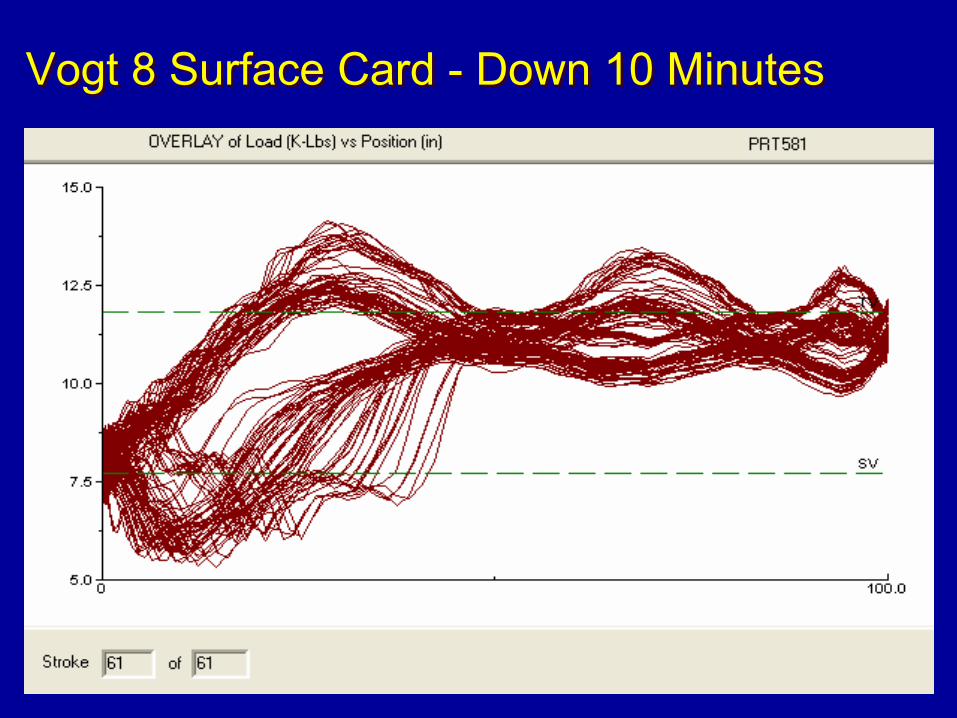
Vogt 8 Surface Card - Down 10 MinutesVogt 8 Surface Card - Down 10 Minutes
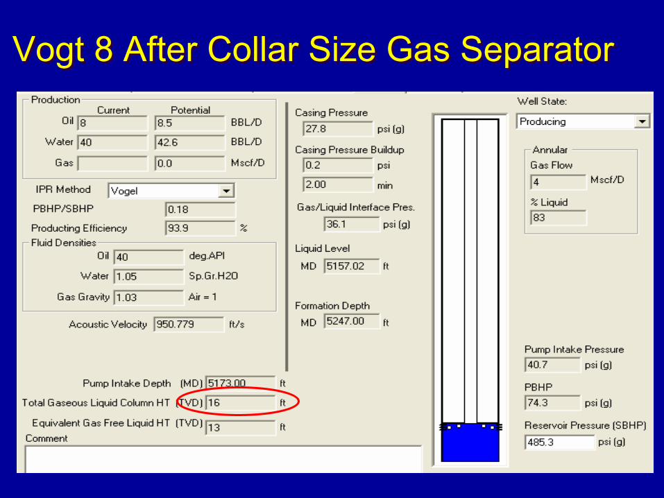
Vogt 8 After Collar Size Gas SeparatorVogt 8 After Collar Size Gas Separator
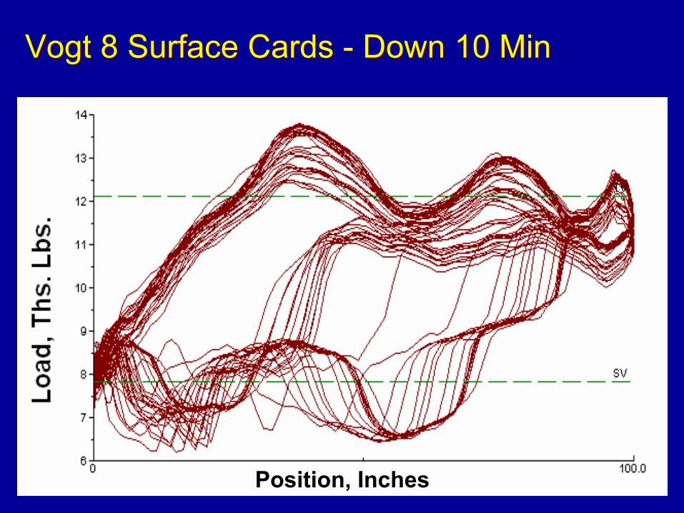
Vogt 8 Surface Cards - Down 10 MinVogt 8 Surface Cards - Down 10 Min
Position, Inches
Vogt 8 ResultsVogt 8 Results
The Collar Size Gas Separator was successful. It separated the gas from the liquid and allowed only liquid to enter the pump as long as liquid was present in the wellbore.
The Collar Size Gas Separator was successful. It separated the gas from the liquid and allowed only liquid to enter the pump as long as liquid was present in the wellbore.
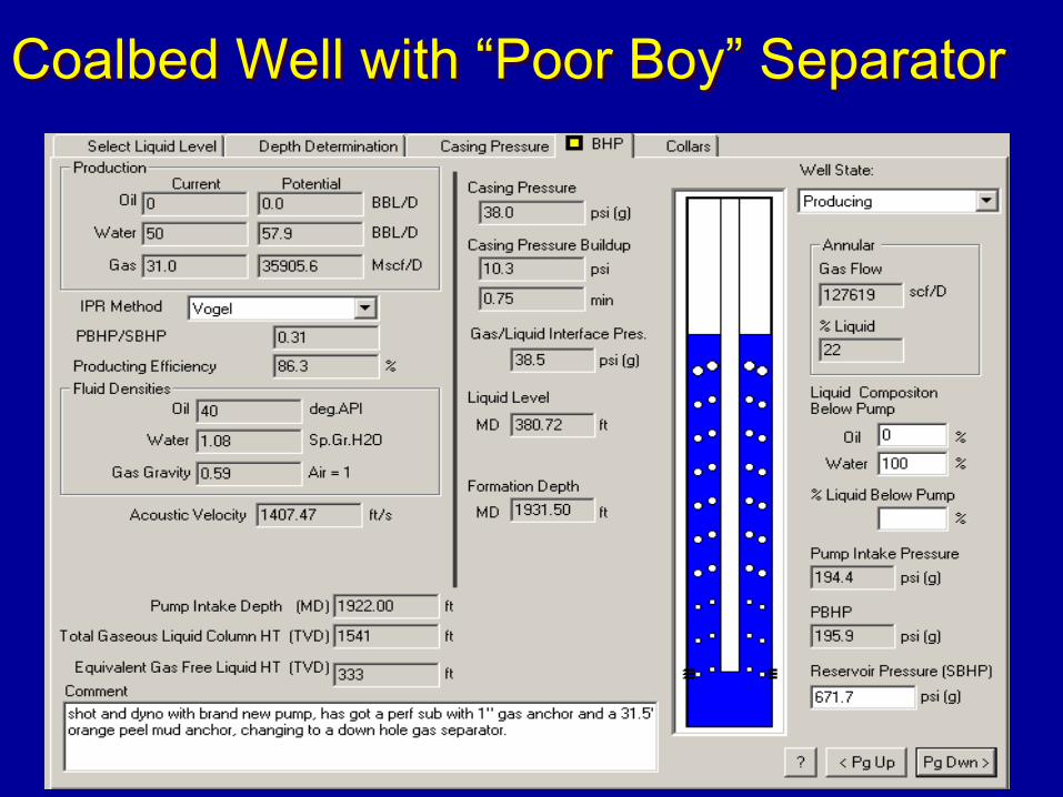
Coalbed Well with “Poor Boy” SeparatorCoalbed Well with “Poor Boy” Separator
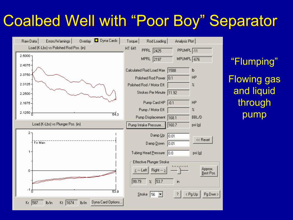
Coalbed Well with “Poor Boy” SeparatorCoalbed Well with “Poor Boy” Separator
“Flumping”
Flowing gas and liquid through pump
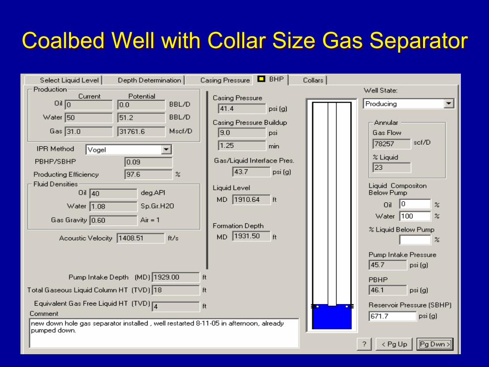
Coalbed Well with Collar Size Gas SeparatorCoalbed Well with Collar Size Gas Separator
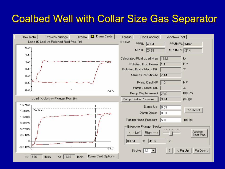
Coalbed Well with Collar Size Gas SeparatorCoalbed Well with Collar Size Gas Separator
Coalbed Well ResultsCoalbed Well Results
The Collar Size Gas Separator was successful. It separated free gas from water and allowed only water to enter the pump as long as water was present in the wellbore above the separator.
The Collar Size Gas Separator was successful. It separated free gas from water and allowed only water to enter the pump as long as water was present in the wellbore above the separator.
5
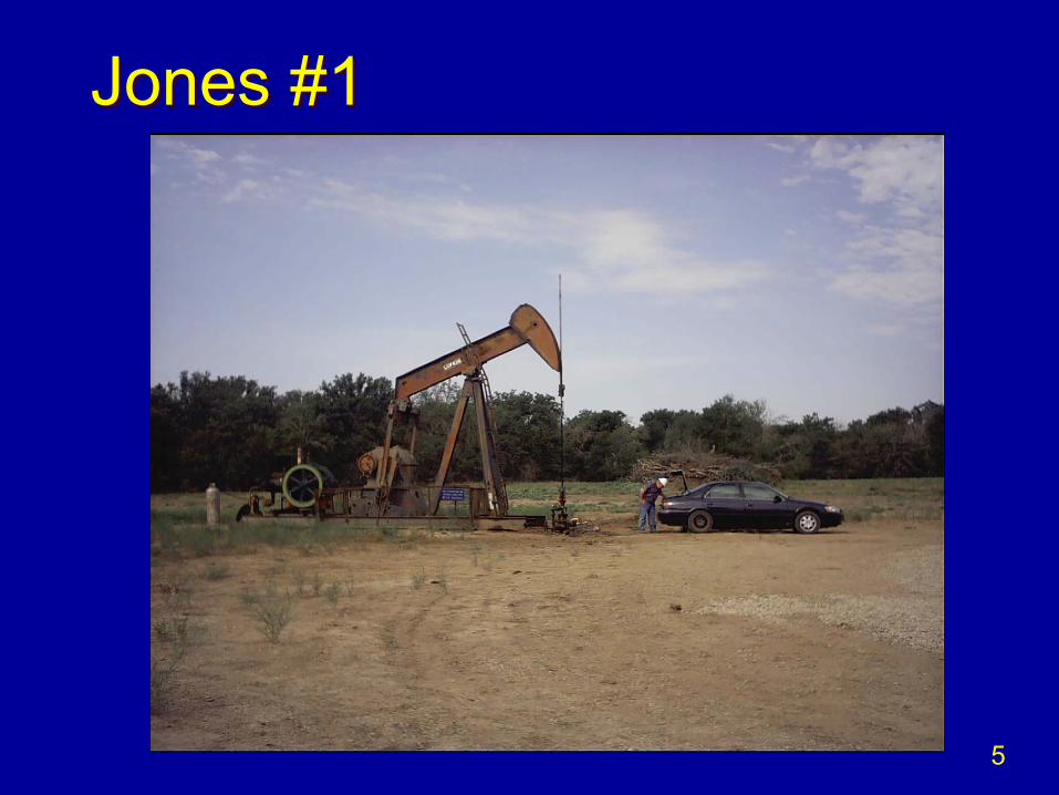
Jones #1Jones #1
5
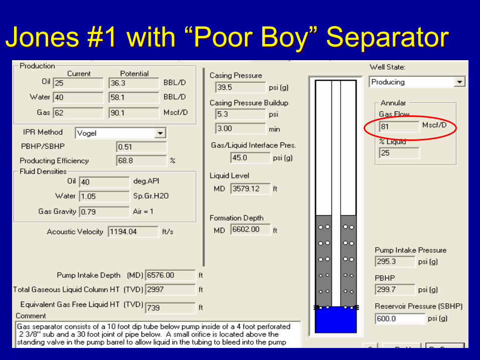
Jones #1 with “Poor Boy” SeparatorJones #1 with “Poor Boy” Separator
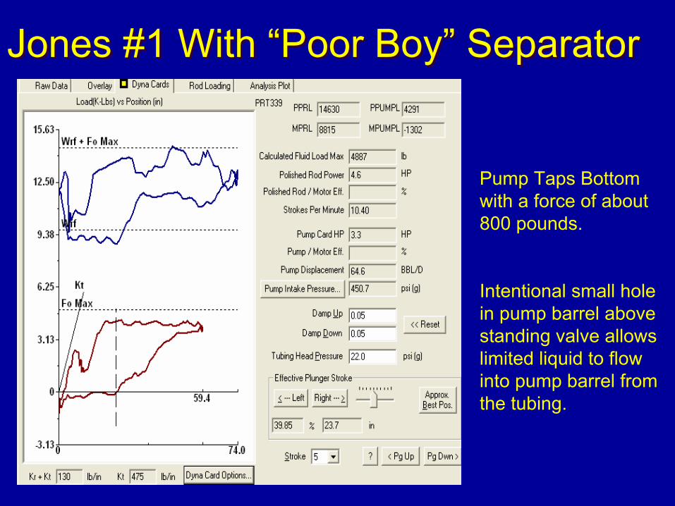
Jones #1 With “Poor Boy” SeparatorJones #1 With “Poor Boy” Separator
Pump Taps Bottom with a force of about 800 pounds.
Intentional small hole in pump barrel above standing valve allows limited liquid to flow into pump barrel from the tubing.
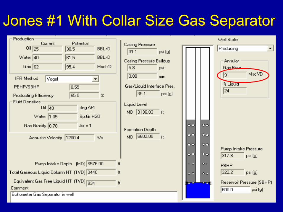
Jones #1 With Collar Size Gas SeparatorJones #1 With Collar Size Gas Separator
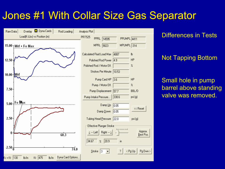
Jones #1 With Collar Size Gas SeparatorJones #1 With Collar Size Gas Separator
Differences in Tests
Not Tapping Bottom
Small hole in pump barrel above standing valve was removed.
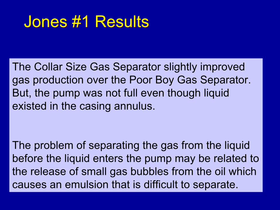
Jones #1 ResultsJones #1 Results
The Collar Size Gas Separator slightly improved gas production over the Poor Boy Gas Separator. But, the pump was not full even though liquid existed in the casing annulus.
The problem of separating the gas from the liquid before the liquid enters the pump may be related to the release of small gas bubbles from the oil which causes an emulsion that is difficult to separate.
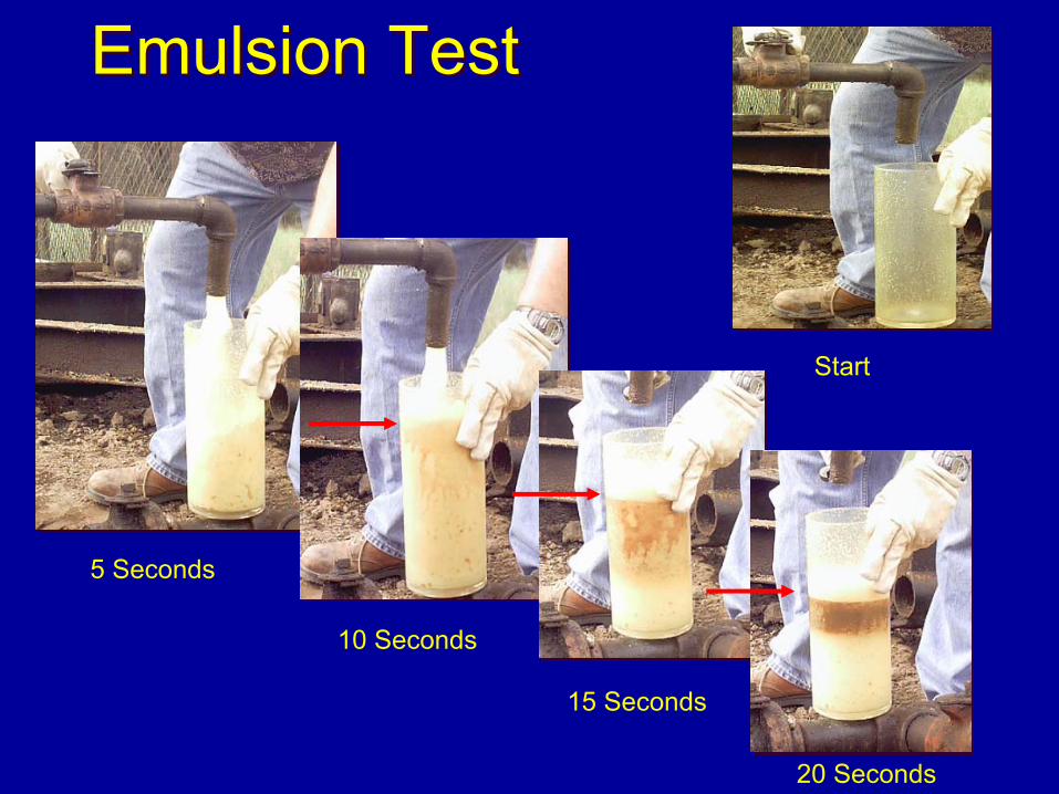
Emulsion TestEmulsion Test
5 Seconds
10 Seconds
15 Seconds
20 Seconds
Start
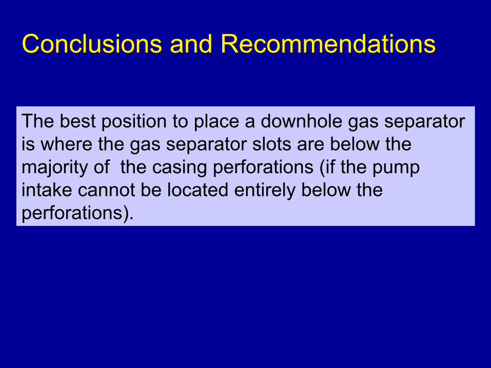
Conclusions and RecommendationsConclusions and Recommendations
The best position to place a downhole gas separator is where the gas separator slots are below the majority of the casing perforations (if the pump intake cannot be located entirely below the perforations).
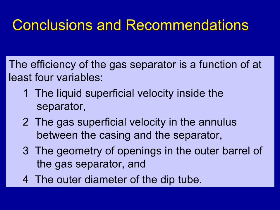
Conclusions and RecommendationsConclusions and Recommendations
The efficiency of the gas separator is a function of at least four variables:
1 The liquid superficial velocity inside the separator,
2 The gas superficial velocity in the annulus between the casing and the separator,
3 The geometry of openings in the outer barrel of the gas separator, and
4 The outer diameter of the dip tube.
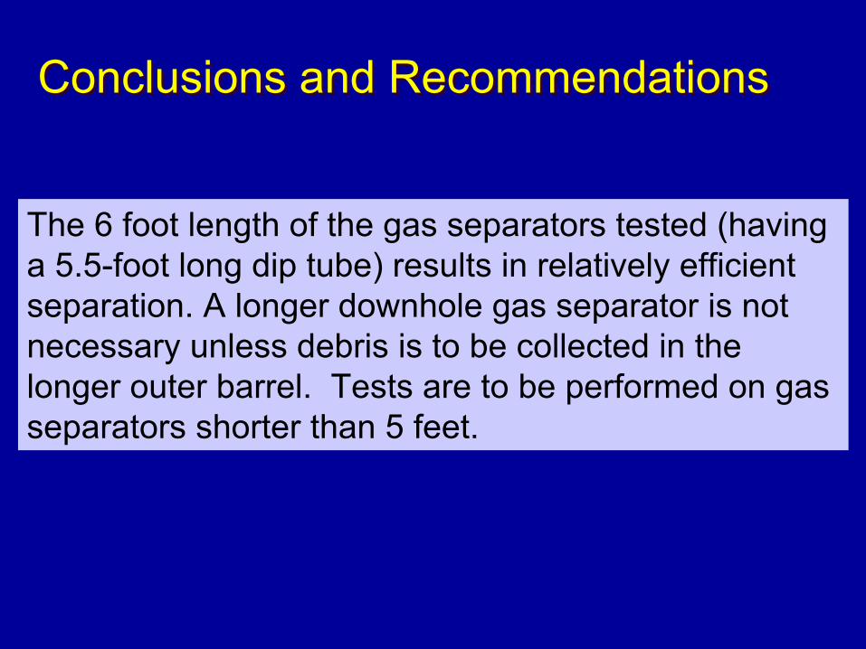
Conclusions and RecommendationsConclusions and Recommendations
The 6 foot length of the gas separators tested (having a 5.5-foot long dip tube) results in relatively efficient separation. A longer downhole gas separator is not necessary unless debris is to be collected in the longer outer barrel. Tests are to be performed on gas separators shorter than 5 feet.
Conclusions and RecommendationsConclusions and Recommendations
The laboratory tests were performed with water and the results should apply to water producing wells.
Conclusions and RecommendationsConclusions and Recommendations
The Jones # 1 field testing of the Collar Size gas separator indicates that gas separator performance is affected by foaming oil conditions.
The field test indicates that additional work should be performed on water, oil and gas mixtures especially when gas is being released from the oil in small bubbles.
Ongoing Project - Future TestsOngoing Project - Future Tests
A variety of geometric port shapes
Shorter dip tube lengths
More viscous liquids
Intermittent flow

Questions ??