Embed Size (px)
Citation preview
Oil & Natural Gas Technology
DOE Award No.: DE-FC26-06NT15486
Reporting Period: October 2004 to June 2008
Final Report HIGH-POWER TURBODRILL AND DRILL BIT FOR
DRILLING WITH COILED TUBING
Submitted by:
Technology International, Inc.
2103 River Falls Drive
Kingwood, Texas 77339-3154
Prepared by:
Principal Investigator
Robert Radtke
David Glowka
Dr. Man Mohan Rai
NASA AMES Research Center
Project Manager
Dr. David Conroy
Tim Beaton
Rocky Seale
Joseph Hanna
Smith Neyrfor
Homer Robertson
Terra Tek Drilling Laboratory
Prepared for:
United States Department of Energy
National Energy Technology Laboratory
July 2011
Office of Fossil Energy
High-Power Turbodrill and Drillbit for Drilling with Coiled Tubing DE-FC26-06NT15486
i
Notice
This report was prepared as an account of work sponsored by an agency of the United States Government.
Neither the United States Government nor any agency thereof, nor any of their employees, makes any
warranty, express or implied, or assumes any legal liability or responsibility for the accuracy,
completeness, or usefulness of any information, apparatus, product, or process disclosed, or represents
that its use would not infringe privately owned rights. Reference herein to any specific commercial
product, process, or service by trade name, trademark, manufacturer, or otherwise does not necessarily
constitute or imply its endorsement, recommendation, or favoring by the United States Government or
any agency thereof. The views and opinions of authors expressed herein do not necessarily state or reflect
those of the United States Government or any agency thereof.
High-Power Turbodrill and Drillbit for Drilling with Coiled Tubing DE-FC26-06NT15486
ii
Preface
Dr. Steve Holditch, 2002 President of the Society of Petroleum Engineers, said, “To economically recover
gas, we need to learn how to drill smaller boreholes more rapidly and less expensively.” However,
achieving this goal of increased drilling efficiency does not necessarily mean using a conventional rotary
drilling rig. Coiled tubing units increasingly are being used to drill for oil and natural gas deposits at
lower costs relative to the costs for using a conventional drilling rig and with a much smaller
environmental footprint. In many applications, coiled tubing drilling can be a cost-effective alternative for
drilling highly deviated wells or drilling new hole sections in existing wells.
The ability of a coiled tubing unit to achieve the drilling objectives for a well are often driven by the
capabilities of the downhole motor or Turbodrill used to convert the hydraulic energy of the drilling fluid
into mechanical energy for driving the drill bit. In the past, smaller diameter downhole motors and
Turbodrills were designed primarily for workover and remedial operations and often lacked the power
and downhole life characteristics necessary for more demanding drilling operations.
The purpose of this project was to demonstrate that the development of a more powerful high-speed
Turbodrill and high-temperature drill bit will reduce the cost per foot drilled and expand the use of coiled
tubing units for drilling purposes.
High-Power Turbodrill and Drillbit for Drilling with Coiled Tubing DE-FC26-06NT15486
iii
Abstract
Commercial introduction of Microhole Technology to the gas and oil drilling industry requires an
effective downhole drive mechanism which operates efficiently at relatively high RPM and low bit weight
for delivering efficient power to the special high RPM drill bit for ensuring both high penetration rate and
long bit life. This project entails developing and testing a more efficient 2-7/8 in. diameter Turbodrill and
a novel 4-1/8 in. diameter drill bit for drilling with coiled tubing. The high-power Turbodrill were
developed to deliver efficient power, and the more durable drill bit employed high-temperature cutters
that can more effectively drill hard and abrasive rock. This project teams Schlumberger Smith Neyrfor
and Smith Bits, and NASA AMES Research Center with Technology International, Inc (TII), to deliver a
downhole, hydraulically-driven power unit, matched with a custom drill bit designed to drill 4-1/8 in.
boreholes with a purpose-built coiled tubing rig.
The U.S. Department of Energy National Energy Technology Laboratory has funded Technology
International Inc. Houston, Texas to develop a higher power Turbodrill and drill bit for use in drilling
with a coiled tubing unit. This project entails developing and testing an effective downhole drive
mechanism and a novel drill bit for drilling “microholes” with coiled tubing. The new higher power
Turbodrill is shorter, delivers power more efficiently, operates at relatively high revolutions per minute,
and requires low weight on bit. The more durable thermally stable diamond drill bit employs high-
temperature TSP (thermally stable) diamond cutters that can more effectively drill hard and abrasive rock.
Expectations are that widespread adoption of microhole technology could spawn a wave of "infill
development" drilling of wells spaced between existing wells, which could tap potentially billions of
barrels of bypassed oil at shallow depths in mature producing areas. At the same time, microhole coiled
tube drilling offers the opportunity to dramatically cut producers' exploration risk to a level comparable to
that of drilling development wells.
Together, such efforts hold great promise for economically recovering a sizeable portion of the estimated
remaining shallow (less than 5,000 feet subsurface) oil resource in the United States. The DOE estimates
this U.S. targeted shallow resource at 218 billion barrels. Furthermore, the smaller "footprint" of the
lightweight rigs utilized for microhole drilling and the accompanying reduced drilling waste disposal
volumes offer the bonus of added environmental benefits. DOE analysis shows that microhole
technology has the potential to cut exploratory drilling costs by at least a third and to slash development
drilling costs in half.
High-Power Turbodrill and Drillbit for Drilling with Coiled Tubing DE-FC26-06NT15486
iv
Table of Contents
EXECUTIVE SUMMARY...............................................................................................................1
INTRODUCTION...............................................................................................................................3
RESULTS...............................................................................................................................7
Turbodrill Redesign for High Efficiency...........................................................................7
Drill Bit Design for High Rotary Speeds.............................................................................9
Catoosa Field Test…..…………………….….……….……..………….……………….27
Terra Tek Laboratory Drilling Tests..................................................................................29
INSTRUMENTATION, CONTROLS, AND DATA ACQUISITION.................................30
Test Parameters.................................................................................................................30
Test Rocks..........................................................................................................................31
TEST RESULTS.............................................................................................................................32
Test 1- NASA Blade Turbodrill Drilling White Sierra Granite with an
Impregnated Diamond Drill Bit .............................................................................34
Test 2- NASA Blade Turbodrill Drilling Sandstone with an
Impregnated Diamond Drill Bit ..............................................................................35
Test 3- NASA Blade Turbodrill Drilling White Sierra Granite with a PDC Drill Bit .....36
Test 4- NASA Blade Turbodrill Drilling Sandstone with a PDC Drill Bit ......................37
Test 5- HEAT Blade Turbodrill Drilling Granite with an
Impregnated Diamond Drill Bit ..............................................................................38
Test 6- HEAT Blade Turbodrill Drilling Sandstone with an Impregnated Diamond
Drill Bit ................................................................................................................39
Test 7 and 8 – Heat Turbodrill Drilling Granite and Sandstone with a PDC Drill Bit.....40
Test 9 and 10 – The Commercial Turbodrill Drilling Granite and Sandstone
with an Impregnated Diamond Drill Bit...............................................................40
Test 11 Commercial Mk2 Blade Turbodrill Drilling granite with a PDC Drill Bit .........40
Test 12 Commercial Blade Turbodrill Drilling sandstone with a PDC Drill Bit............. 42
CONCLUSIONS……………………………………………………………………………….42
REFERENCES.……………………………………………………………………………..… 44

High-Power Turbodrill and Drillbit for Drilling with Coiled Tubing DE-FC26-06NT15486
v
ACKNOWLEDGEMENTS……………….……………………………………………………45
LIST OF ACRONYMS.……...…………….…… …………………………….……………….46
High-Power Turbodrill and Drillbit for Drilling with Coiled Tubing DE-FC26-06NT15486
vi
List of Figures
Figure 1: Direct Drive Turbodrill Components............................................................................. 5
Figure 2: Computational Fluid Dynamics...................................................................................... 8
Figure 3: Smith Neyrfor Flow Test Facility....................................................................................9
Figure 4: Effect of Weight-on-bit to Achieve Constant ROP as the Cutters Wear ......................12
Figure 5: Cutter wearflat-area distributions at 100 RPM, 30 ft/hr ...............................................13
Figure 6: Cutter wearflat-area distributions at 2,200 RPM .........................................................13
Figure 7: Maximum cutter wearflat temperatures at both rotary speeds.......................................14
Figure 8: Cutter 14 Wearflat Temperature at 2,200 RPM ............................................................15
Figure 9: ROP response to WOB .................................................................................................16
Figure 10: Drilling Torque vs. ROP .............................................................................................16
Figure 11: Bit Imbalance-force Ratio (Bit Side Force/WOB....................................................... 17
Figure 12: Cutting profiles for drill bit at 100 RPM .....................................................................18
Figure 13: Cutting profiles for drill bit at 2200 RPM ....................................................................18
Figure 14: Forces on Cutter While Drilling ..................................................................................19
Figure 15: PDC Cutter Wear Rate vs. Temperature .....................................................................19
Figure 16: Cutter Wear Flats .........................................................................................................20
Figure 17: PDC Cutter Cooling Coefficients ...............................................................................20
Figure 18: Cutter Heat Flux ..........................................................................................................21
Figure 19: Typical FE Temperature Result ..................................................................................21
Figure 20: Temperature of TSP and PDC Cutters ........................................................................22
Figure 21: Effect of Rock-Chip Build-up on Temperature ...........................................................22
Figure 22: Cutter Heat Flux ..........................................................................................................23
Figure 23: Gage Cutter Temperature............................................................................................ 23
Figure 24: New DragBit Simulator ..............................................................................................24
Figure 25: Forces on Cutters While Drilling ................................................................................25
Figure 26: Effective Depth of Cut ................................................................................................25
Figure 27: Cutter Penetrating Stresses .........................................................................................26
Figure 28: The Turbodrills for the Catoosa I Test .......................................................................27
Figure 29: Fixed Cutter 4-1/8” Bit for Coiled Tubing Drilling ...................................................27
Figure 30: Impregnated 4-1/8” Bit for Coiled Tubing Drilling ...................................................27
Figure 31: Turbodrill Drilling Simulator .....................................................................................28
Figure 32: Turbodrill Power Section ...........................................................................................29
High-Power Turbodrill and Drillbit for Drilling with Coiled Tubing DE-FC26-06NT15486
vii
Figure 33: Test Rock .....................................................................................................................31
Figure 34: Typical Turbodrilling Test Data ..................................................................................32
Figure 35: Test 1 Turbodrilling Test Data ....................................................................................33
Figure 36: Test 1 Nearly Perfect Borehole ..................................................................................34
Figure 37: Test 1 Drill Bit After Test............................................................................................34
Figure 38: Test 2 Turbodrilling Test Data.....................................................................................34
Figure 39: Test 2 Nearly Perfect Borehole....................................................................................35
Figure 40: Test 3 Turbodrilling Test Data.....................................................................................35
Figure 41: Test 3 Misaligned Borehole........................................................................................ 36
Figure 42: Test 4 Turbodrilling Test Data.....................................................................................36
Figure 43: Test 4 Drill Bit After Test............................................................................................37
Figure 44: Test 5 Turbodrilling Test Data.....................................................................................37
Figure 45: Test 5 Misaligned Borehole.........................................................................................38
Figure 46: Test 6 Turbodrilling Test Data.....................................................................................38
Figure 47: Test 6 Misaligned Borehole.........................................................................................39
Figure 48: Test 6 Drill Bit After Test............................................................................................39
Figure 49: Test 11 Turbodrilling Test Data...................................................................................40
Figure 50: Test 11 Nearly Perfect Borehole.................................................................................40
Figure 51: Test 12 Turbodrilling Test Data..................................................................................41

High-Power Turbodrill and Drillbit for Drilling with Coiled Tubing DE-FC26-06NT15486
viii
List of Tables
Table 1: Test matrix showing the turbine, bit, rock, and flow and WOB used for each test..........30
Table 2: Test Rock Physical Properties..........................................................................................31
Table 3: Planned Test Operating Parameters.....................................................................................33
High-Power Turbodrill and Drillbit for Drilling with Coiled Tubing DE-FC26-06NT15486
1
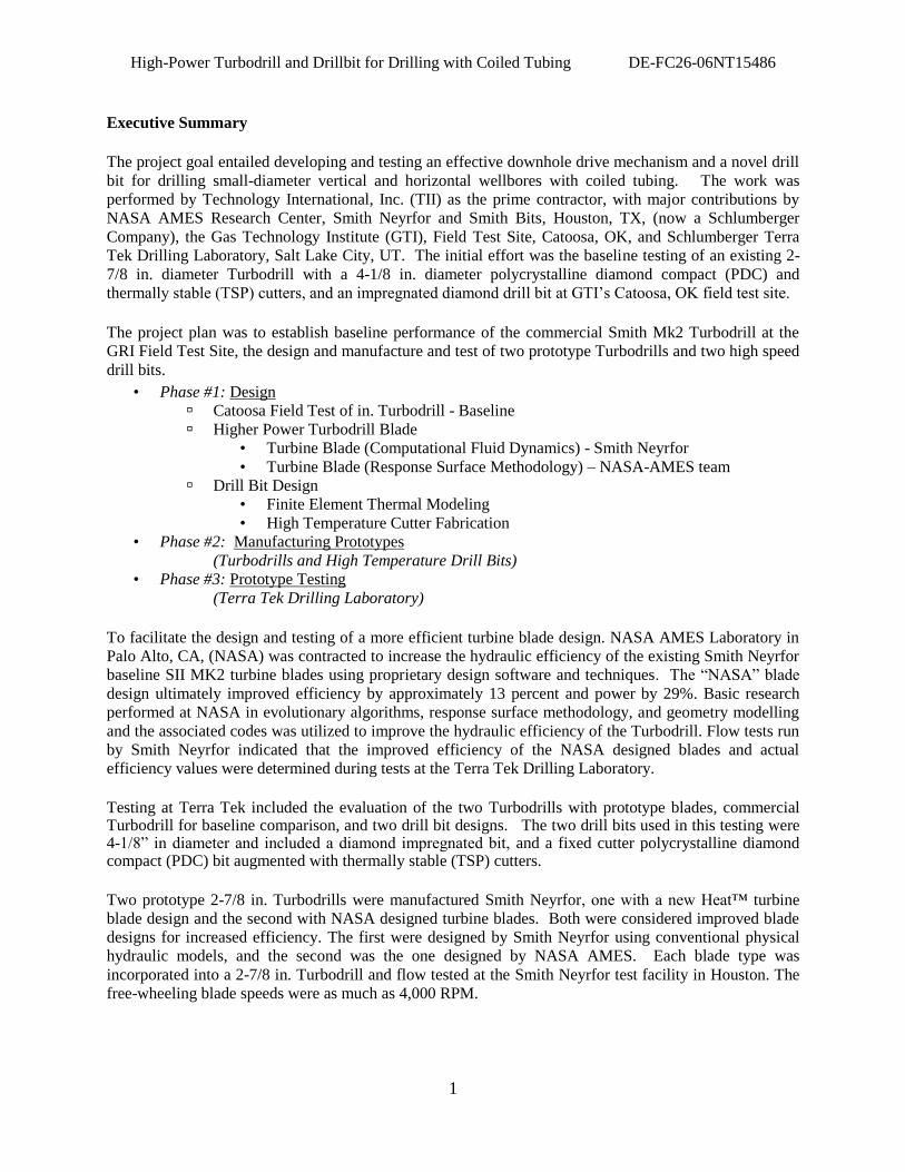
Executive Summary
The project goal entailed developing and testing an effective downhole drive mechanism and a novel drill
bit for drilling small-diameter vertical and horizontal wellbores with coiled tubing. The work was
performed by Technology International, Inc. (TII) as the prime contractor, with major contributions by
NASA AMES Research Center, Smith Neyrfor and Smith Bits, Houston, TX, (now a Schlumberger
Company), the Gas Technology Institute (GTI), Field Test Site, Catoosa, OK, and Schlumberger Terra
Tek Drilling Laboratory, Salt Lake City, UT. The initial effort was the baseline testing of an existing 2-
7/8 in. diameter Turbodrill with a 4-1/8 in. diameter polycrystalline diamond compact (PDC) and
thermally stable (TSP) cutters, and an impregnated diamond drill bit at GTI‟s Catoosa, OK field test site.
The project plan was to establish baseline performance of the commercial Smith Mk2 Turbodrill at the
GRI Field Test Site, the design and manufacture and test of two prototype Turbodrills and two high speed
drill bits.
• Phase #1: Design
Catoosa Field Test of in. Turbodrill - Baseline
Higher Power Turbodrill Blade
• Turbine Blade (Computational Fluid Dynamics) - Smith Neyrfor
• Turbine Blade (Response Surface Methodology) – NASA-AMES team
Drill Bit Design
• Finite Element Thermal Modeling
• High Temperature Cutter Fabrication
• Phase #2: Manufacturing Prototypes
(Turbodrills and High Temperature Drill Bits)
• Phase #3: Prototype Testing
(Terra Tek Drilling Laboratory)
To facilitate the design and testing of a more efficient turbine blade design. NASA AMES Laboratory in
Palo Alto, CA, (NASA) was contracted to increase the hydraulic efficiency of the existing Smith Neyrfor
baseline SII MK2 turbine blades using proprietary design software and techniques. The “NASA” blade
design ultimately improved efficiency by approximately 13 percent and power by 29%. Basic research
performed at NASA in evolutionary algorithms, response surface methodology, and geometry modelling
and the associated codes was utilized to improve the hydraulic efficiency of the Turbodrill. Flow tests run
by Smith Neyrfor indicated that the improved efficiency of the NASA designed blades and actual
efficiency values were determined during tests at the Terra Tek Drilling Laboratory.
Testing at Terra Tek included the evaluation of the two Turbodrills with prototype blades, commercial Turbodrill for baseline comparison, and two drill bit designs. The two drill bits used in this testing were 4-1/8” in diameter and included a diamond impregnated bit, and a fixed cutter polycrystalline diamond compact (PDC) bit augmented with thermally stable (TSP) cutters.
Two prototype 2-7/8 in. Turbodrills were manufactured Smith Neyrfor, one with a new Heat™ turbine
blade design and the second with NASA designed turbine blades. Both were considered improved blade
designs for increased efficiency. The first were designed by Smith Neyrfor using conventional physical
hydraulic models, and the second was the one designed by NASA AMES. Each blade type was
incorporated into a 2-7/8 in. Turbodrill and flow tested at the Smith Neyrfor test facility in Houston. The
free-wheeling blade speeds were as much as 4,000 RPM.
High-Power Turbodrill and Drillbit for Drilling with Coiled Tubing DE-FC26-06NT15486
2
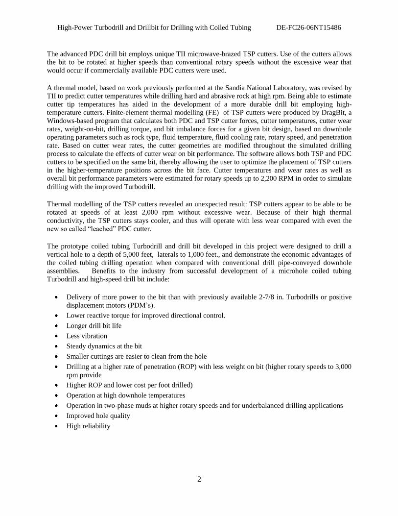
The advanced PDC drill bit employs unique TII microwave-brazed TSP cutters. Use of the cutters allows
the bit to be rotated at higher speeds than conventional rotary speeds without the excessive wear that
would occur if commercially available PDC cutters were used.
A thermal model, based on work previously performed at the Sandia National Laboratory, was revised by
TII to predict cutter temperatures while drilling hard and abrasive rock at high rpm. Being able to estimate
cutter tip temperatures has aided in the development of a more durable drill bit employing high-
temperature cutters. Finite-element thermal modelling (FE) of TSP cutters were produced by DragBit, a
Windows-based program that calculates both PDC and TSP cutter forces, cutter temperatures, cutter wear
rates, weight-on-bit, drilling torque, and bit imbalance forces for a given bit design, based on downhole
operating parameters such as rock type, fluid temperature, fluid cooling rate, rotary speed, and penetration
rate. Based on cutter wear rates, the cutter geometries are modified throughout the simulated drilling
process to calculate the effects of cutter wear on bit performance. The software allows both TSP and PDC
cutters to be specified on the same bit, thereby allowing the user to optimize the placement of TSP cutters
in the higher-temperature positions across the bit face. Cutter temperatures and wear rates as well as
overall bit performance parameters were estimated for rotary speeds up to 2,200 RPM in order to simulate
drilling with the improved Turbodrill.
Thermal modelling of the TSP cutters revealed an unexpected result: TSP cutters appear to be able to be
rotated at speeds of at least 2,000 rpm without excessive wear. Because of their high thermal
conductivity, the TSP cutters stays cooler, and thus will operate with less wear compared with even the
new so called “leached” PDC cutter.
The prototype coiled tubing Turbodrill and drill bit developed in this project were designed to drill a
vertical hole to a depth of 5,000 feet, laterals to 1,000 feet., and demonstrate the economic advantages of
the coiled tubing drilling operation when compared with conventional drill pipe-conveyed downhole
assemblies. Benefits to the industry from successful development of a microhole coiled tubing
Turbodrill and high-speed drill bit include:
Delivery of more power to the bit than with previously available 2-7/8 in. Turbodrills or positive
displacement motors (PDM‟s).
Lower reactive torque for improved directional control.
Longer drill bit life
Less vibration
Steady dynamics at the bit
Smaller cuttings are easier to clean from the hole
Drilling at a higher rate of penetration (ROP) with less weight on bit (higher rotary speeds to 3,000
rpm provide
Higher ROP and lower cost per foot drilled)
Operation at high downhole temperatures
Operation in two-phase muds at higher rotary speeds and for underbalanced drilling applications
Improved hole quality
High reliability
High-Power Turbodrill and Drillbit for Drilling with Coiled Tubing DE-FC26-06NT15486
3
Introduction
Dr. Steve Holditch, 2002 president of the Society of Petroleum Engineering said “To economically
recover gas we need to learn how to drill smaller boreholes more rapidly and less expensively.” The
American Petroleum Institute publication, Coiled Tubing Drilling: “A Novel Alternative to Conventional
Drill Rigs” states that lower cost drilling techniques are needed to economically drill shallow gas and oil
wells needed to reach the reserves of oil and natural gas to get to work and school, harvest our food and
run our businesses, appliances, computers and factories. But drilling today does not necessarily mean
using a conventional rotary drilling rig. Coiled tubing units are being increasingly used to drill for oil and
natural gas deposits for less cost and with a much smaller environmental footprint. With conventional
drilling rigs, hundreds of 30 foot sections of rigid drill pipe are continuously threaded together to reach
deep below the surface. Large crews are required to thread the pipe together after each 30 feet of hole is
drilled. To ensure that sufficient weight is put on the drill bit to destroy the rock formations, heavy weight
drill collars are placed in the drilling assembly below the drill pipe. To drill, the entire string of pipe is
spun rapidly so that the bit on the end of the drill pipe can penetrate the rock formations. This requires
lots of power and a large derrick to hoist the drill pipe up so that it can be threaded together. Each time
that the bit becomes dull, the entire string of pipe has to be pulled up and unthreaded a joint at a time to
remove the bit from the hole.
A cost-effective alternative, especially for drilling highly deviated wells or drilling new hole sections in
existing wells is coiled tubing drilling. Coiled tubing units consist of a continuous length of flexible pipe
that is coiled onto a spool, much in the way that cable is spooled. Thus, crews are not needed to thread
the pipe together and large derricks are not needed to hoist the pipe in the air for threading and
unthreading. Instead of rotating the entire string of drill pipe to turn the bit, the bit is turned by pumping
mud through a turbine motor, known as a Turbodrill which spins only the bit. Mud is used in all drilling
operations to cool the bit, remove rock pieces from the hole, contain formation pressures and keep the
hole from collapsing. The benefits of using coiled tubing units for drilling include:
The units require about half the surface area that a conventional drilling rig requires. The
units require less power so there is less fuel consumption and emissions during drilling.
Noise levels are 18 percent lower than with conventional rigs.
There is less visual impact as the units are small with no large derrick tower.
The units require fewer workers and have less rotating equipment, so they are generally safer
to operate.
Smaller volumes of drilling mud are needed, and a smaller volume of rock cuttings is created
during drilling because the drilled holes are a smaller diameter.
Set-up time is greatly reduced. Drilling time is also reduced because the drill pipe does not
need to be threaded and unthreaded. Changing dull bits is also quicker because the pipe is
just rolled back on the spool to pull the bit out of the hole.
Coiled tubing units, because they are smaller and lighter than conventional drilling rigs, are
more easily transported by truck, barge, ship or helicopter.
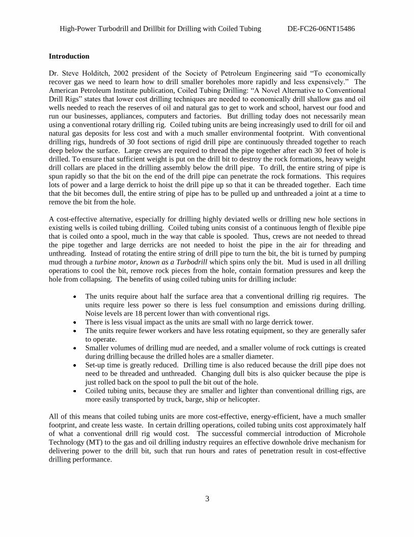
All of this means that coiled tubing units are more cost-effective, energy-efficient, have a much smaller
footprint, and create less waste. In certain drilling operations, coiled tubing units cost approximately half
of what a conventional drill rig would cost. The successful commercial introduction of Microhole
Technology (MT) to the gas and oil drilling industry requires an effective downhole drive mechanism for
delivering power to the drill bit, such that run hours and rates of penetration result in cost-effective
drilling performance.
High-Power Turbodrill and Drillbit for Drilling with Coiled Tubing DE-FC26-06NT15486
4
Applications for Coil Tubing Downhole Motors include drilling, production remediation, and shallow
seismic exploration holes for burying arrays, and Vertical Seismic Profiling (VSP) during the drilling
operation. Initial tests of prototype hardware was conducted at drilling research centers to expedite the
testing process and to ensure maintenance of carefully controlled operating conditions not compromised
by customers‟ operational drilling requirements. However, because of Smith Neyrfor‟s position as the
leading provider of Turbodrilling services in the oilfield, much of the subsequent testing was
accomplished in wells drilled with conventional drill pipe and in workover applications using
conventional coiled tubing rigs for operations such as scale removal. This approach served to both reduce
development time and minimize total costs necessary to meet project objectives.
The use of turbine motors ((i.e. Turbodrills) is over a hundred years old and was first applied to oilfield
drilling in the USSR in 1924. Neyrfor introduced the first steerable downhole drilling motor in 1982.
Neyrfor was purchased by Smith International. Advanced PDC bearings were introduced into Turbodrills
in 1992. Bent housing Turbodrills were also introduced in 1992. Speed reduction gearing for Turbodrills
was introduced in 2001.
A Turbodrill power section is entirely metallic (metallic turbine blades, metallic shaft, metallic housing,
etc.), therefore, the tool is extremely resistant to high temperatures and high pressures. Historically,
Turbodrills have proven to be the most reliable drive mechanism in elevated temperature environments.
In many cases, Turbodrills are the exclusive drive mechanism used in high temperature/high pressure
areas because of the tool‟s ability to reliably operate in extreme environments.
Many critical developments have contributed to the growing success of Turbodrills and high speed drill
bits. The term „high speed drill bits‟ (HS bits) is meant to describe any type of drill bit that is compatible
with high speed Turbodrills which, depending on tool size, will produce an output speed from 700 to
about 2,000 RPM. Most of the developments associated with this system have been focused on
improving the durability and reliability of the system. Because Turbodrills and HS bits are both made
from very expensive, tight tolerance components, there must be a significant performance benefit when
using the system to justify the increased cost of the system. That benefit can be realized in the form of
improved ROP, improved run length, reduced trips, improved hole quality, improved directional
performance, improved hole cleaning, or a variety of other factors. However, in most cases, it is easiest
to justify the expense of the system through either an increase in ROP or a reduction in the number of
required trips. Therefore, the durability and reliability of the Turbodrill/HS bit system is of primary
importance
Some of the most important developments concerning the durability and reliability of this drilling system
are found in Turbodrill bearings. The bearings, both radial and thrust, maintain the appropriate turbine
blade position, radially and axially, allowing them to perform as designed. Since Turbodrills are very
long lasting tools that run in high RPM ranges, the development of bearing technology has been crucial to
the durability of the tool. One of the most important developments in bearing technology has been the
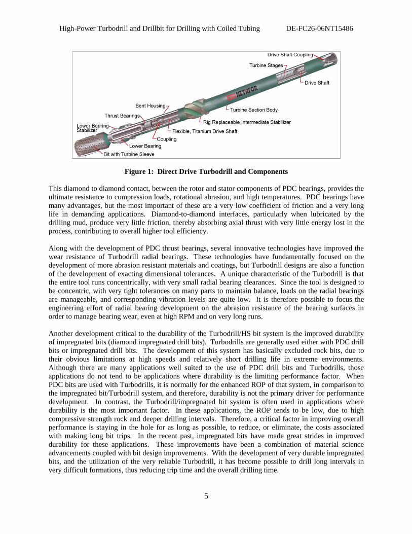
optimization of PDC thrust bearings. Bearings, through diamond to diamond contact, support the axial
thrust and rotations created by the turbine blades and reside in the bearing section (Figure 1).
High-Power Turbodrill and Drillbit for Drilling with Coiled Tubing DE-FC26-06NT15486
5
Figure 1: Direct Drive Turbodrill and Components
This diamond to diamond contact, between the rotor and stator components of PDC bearings, provides the
ultimate resistance to compression loads, rotational abrasion, and high temperatures. PDC bearings have
many advantages, but the most important of these are a very low coefficient of friction and a very long
life in demanding applications. Diamond-to-diamond interfaces, particularly when lubricated by the
drilling mud, produce very little friction, thereby absorbing axial thrust with very little energy lost in the
process, contributing to overall higher tool efficiency.
Along with the development of PDC thrust bearings, several innovative technologies have improved the
wear resistance of Turbodrill radial bearings. These technologies have fundamentally focused on the
development of more abrasion resistant materials and coatings, but Turbodrill designs are also a function
of the development of exacting dimensional tolerances. A unique characteristic of the Turbodrill is that
the entire tool runs concentrically, with very small radial bearing clearances. Since the tool is designed to
be concentric, with very tight tolerances on many parts to maintain balance, loads on the radial bearings
are manageable, and corresponding vibration levels are quite low. It is therefore possible to focus the
engineering effort of radial bearing development on the abrasion resistance of the bearing surfaces in
order to manage bearing wear, even at high RPM and on very long runs.
Another development critical to the durability of the Turbodrill/HS bit system is the improved durability
of impregnated bits (diamond impregnated drill bits). Turbodrills are generally used either with PDC drill
bits or impregnated drill bits. The development of this system has basically excluded rock bits, due to
their obvious limitations at high speeds and relatively short drilling life in extreme environments.
Although there are many applications well suited to the use of PDC drill bits and Turbodrills, those
applications do not tend to be applications where durability is the limiting performance factor. When
PDC bits are used with Turbodrills, it is normally for the enhanced ROP of that system, in comparison to
the impregnated bit/Turbodrill system, and therefore, durability is not the primary driver for performance
development. In contrast, the Turbodrill/impregnated bit system is often used in applications where
durability is the most important factor. In these applications, the ROP tends to be low, due to high
compressive strength rock and deeper drilling intervals. Therefore, a critical factor in improving overall
performance is staying in the hole for as long as possible, to reduce, or eliminate, the costs associated
with making long bit trips. In the recent past, impregnated bits have made great strides in improved
durability for these applications. These improvements have been a combination of material science
advancements coupled with bit design improvements. With the development of very durable impregnated
bits, and the utilization of the very reliable Turbodrill, it has become possible to drill long intervals in
very difficult formations, thus reducing trip time and the overall drilling time.
High-Power Turbodrill and Drillbit for Drilling with Coiled Tubing DE-FC26-06NT15486
6
In the drilling environment, the easiest performance measure is the ROP. For fixed cutter bits, whether a
PDC drill bit or impregnated bit, there is a ROP limit attributed with the design of the bit. With an
impregnated bit, the rock is failed through a grinding operation using small natural or synthetic diamonds
as the cutting structure. The diamonds used in these bits have a very low maximum depth of cut (DOC).
Consequently, the most effective method for increasing the ROP for this type of cutting structure is to
increase the RPM. Since each revolution of the bit can only penetrate the rock by a small distance, the
more frequent the revolutions, the faster the overall ROP. As mentioned above, in the design of
impregnated bits over the last few decades, the majority of the development effort has centered on
increasing the durability of the bit. This is due to the fact that most of the formations that are commonly
drilled by impregnated bits are very hard, hard and abrasive, or very abrasive. It has also been proven that
not only higher speeds, but higher power supplied to the bit, will also improve performance in most
instances. However, as indicated above, since the DOC of an impregnated is relatively low, the
maximum attainable ROP of the bit is also relatively low, regardless of the power or weight on bit (WOB)
applied to the bit.
In general, current impregnated diamond drill bit designs are very durable, but often fall behind in ROP
potential when compared to PDC or roller cone bits. This can be understood by evaluating how each type
of cutter fails the rock. Research and development efforts are underway to develop impregnated designs
that will increase the ROP through cutting structure aggressiveness and hydraulic efficiency, without
compromising the durability that is so important to overall performance.
In comparison, PDC bits often achieve good ROP, due to the shearing action by which the rock is failed.
Theoretically, this cutting action can provide a much better penetration rate than the grinding action of an
impregnated bit. However, in harder and/or more abrasive formations, when running at high RPM, the
durability of PDC cutting structures is currently relatively limited, especially when compared to
impregnated bits. That is not to say that there are not applications for running high speed Turbodrills with
PDC bits, there are many such applications. However, the applications that are currently suitable for the
HS Turbodrill/PDC drill bit system tend to be in applications that are either not both hard and abrasive, or
not highly abrasive, regardless of formation strength. Many developments are underway both in PDC
cutting structure design and PDC cutter technology to address the excessive wear issue and allow PDC
drill bit designs to add durability to a good record of ROP. The development of the geared Turbodrill has
also had a beneficial impact on the suitability of PDC drill bits because geared Turbodrills operate at
lower RPM than direct drive Turbodrill.
Many different approaches are currently under investigation to improve the performance of the
Turbodrill/HS drill bit system. Research and development is proceeding on PDC and impregnated bits in
combination with Turbodrill configurations to maximize the system potential. These efforts include
increasing the ROP potential of impregnated bits, increasing the durability of PDC bits, and optimizing
the power delivery of the Turbodrill at the various operating parameters.
PDC bits often achieve good ROP, due to the shearing action by which the rock is failed. However, when
run with Turbodrills in hard and/or abrasive drilling environments, they often wear quite rapidly. Many
developments are underway both in PDC cutting structure design and PDC and thermally stable diamond
cutter technologies to address the excessive wear issue and allow PDC drill bit designs to add durability
to a good record of ROP.
The purpose of the proposed project is to protect the environment, reduce the cost and increase the safety
of drilling 5,000 feet onshore petroleum wells with 1,000 feet laterals. This proposed project delivered a
downhole, hydraulically-driven power unit, matched with a custom drill bit design, with the power
unit/drill bit system designed specifically to provide an optimized combination of run life and penetration
High-Power Turbodrill and Drillbit for Drilling with Coiled Tubing DE-FC26-06NT15486
7
rate when used to drill 4-1/8” boreholes meet these depth and horizontal requirements, with a purpose-
built coiled tubing rig. The goal is an advanced Turbodrill and Drill Bit systems.
Major objectives were to (a) establish a baseline performance by initially drilling with commercially
available 2-7/8 in. Turbodrills and coil tubing bits, (b) increase the performance of turbine and drill bit
components, (c) model the turbine and drilling process to achieve drill bit performance that will deliver
the optimum performance affordable with the Turbodrill-bit combination, (d) manufacture the prototype
Turbodrill and optimized drill bit and demonstrate the improvements in ROP and equipment life while
drilling at the GTI Catoosa field test site, and the Terra Tek Drilling Laboratory.
Results
Initially, a design review was held in Tulsa, OK with the DOE technical staff. The agenda included
(1) Catoosa field test benchmark drilling record with the commercial 2-7/8 in. Smith Neyrfor Turbodrill
and Smith Bits drill bit performance, (2) FE thermal and Neural Network based aerodynamic vane
modelling results, (3) the redesign of the in. Smith Neyrfor Turbodrill, and (4) a coil tubing drill bit
redesign.
A commercial 2-7/8 in. Smith Neyrfor Turbodrill with an “aggressive” Smith Bit drill bit with
polycrystalline diamond cutters (PDC) and thermally stable diamond (TSP) cutters was field tested at the
Gas Technology Institute (GTI) field test site at Catoosa, OK to establish benchmark performance. A
commercial Turbodrill and drill bit hardware for drilling 4-1/8 in diameter hole using existing
Turbodrilling and drill bit technology was used to establish “benchmark” performance at the GTI Catoosa
Test Site using jointed drill pipe and a downhole assembly to simulate coiled tubing drilling. The
downhole assembly included a commercial Smith Neyrfor 2-7/8 in. directional Turbodrill and an
“aggressive” Smith 4-1/8 in fixed cutter drill bit specifically designed with to include thermally stable
diamond cutters. The motor section for the Smith MK2 Turbodrill is designed to rotate at 1,100 to 2,000
RPM depending on mud weight, pressure drop, and flow rate. The drill test was designed to establish a
baseline for the manufacture of prototype Turbodrill and high speed drill bit. The detailed results of the
Catoosa testing are reported herein. Improvements were incorporated into a prototype Turbodrill and drill
bit that was tested at the Terra Tek Drilling Laboratory. The prototype Turbodrills, HEAT and NASA
Turbodrill Redesign for High Efficiency
Turbodrills obtain hydraulic power to rotate a drill bit from the flow of drilling fluids, (mud, foam, or air).
This hydraulic flow is converted to rotary movement by a system of blades within the turbine assembly.
They may be variable pressure profile blades or constant pressure drop blades. The efficiency of the
turbine section rotor and stator blade is the effectiveness to convert hydraulic energy to mechanical
energy in the form of rotation and torque at the bit. The Smith Neyrfor commercial Turbodrill efficiency
is 50%. TII contracted NASA Ames Research Center to apply for the first time to petroleum downhole
Turbodrills, new turbine design software based on an aerodynamic design optimization procedure using
neural networks and “response surface methodology” (RSM). New blade and stator profiles were
successfully designed and tested.
Dr. Man Mohan Rai at the NASA Ames Research Center, Moffett Field, CA has developed a series of
fluid dynamic algorithms and neural networks which have been successfully used for redesign of turbine
blades to optimum efficiency. Dr. Rai produced an improved blade design given the mechanical
operating requirements and hydraulic flow conditions, both steady and unsteady flow. Additionally, since
flow conditions change, it is possible to maintain near-optimal performance levels at otherwise off-design
operating conditions. Additionally, the accuracy to which the optimal shape is manufactured depends on
High-Power Turbodrill and Drillbit for Drilling with Coiled Tubing DE-FC26-06NT15486
8
the manufacturing tolerances and normal wear and tear. These requirements lead to the need for a robust
optimal design solution. Thus, evolutionary algorithms are needed, and the learning of the neural network
is used to achieve robust optimal design solutions. Both traditional response surface methodology (RMS)
and neural networks are incorporated in this design method by a strategy called parameter-based
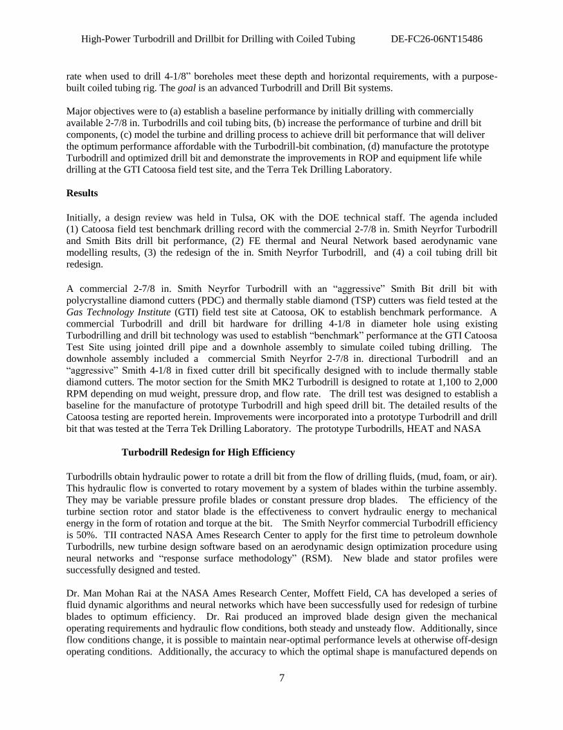
partitioning of the design space. Starting with the reference design, a sequence of turbine vane response
surfaces based on both neural networks and polynomial fits are constructed to traverse the turbine vane
profile in search of the optimal solution. Figure 2 shown below is an illustration of computational fluid
dynamics as it applies to the Turbodrill. To our knowledge, this was the first use of these state-of-the-art
techniques for petroleum Turbodrills. Dr. Rai presented the results of his modelling and methodology
while training Smith Neyrfor project personnel in the use of the system.
Figure 2: Computational Fluid Dynamics
Changes to the turbine blade profiles gave 13% more power per stage, reducing the required number of
stages and further reducing assembly length. Further, the power was increased by 29%. Conventional,
constant pressure drop, turbine blades produce very similar pressure drops, whether the tool is off bottom
with the blades rotating at maximum RPM or stalled out on bottom with no blade rotation. The new
blade profile reduced the pressure drop through the blades as RPM decreases.
Elastomer thrust bearings are used for low temperature and high mud weight applications, while tungsten
carbide radial bearings for high temperature wells, and PDC thrust bearings are used for high temperature
High-Power Turbodrill and Drillbit for Drilling with Coiled Tubing DE-FC26-06NT15486
9
and high mud weight applications. The PDC thrust bearings used on the in. conventional Turbodrill
bearings were tested to review bearing design adequacy for the coiled tubing drilling application, even
though the rated design life exceeds 200 hours.
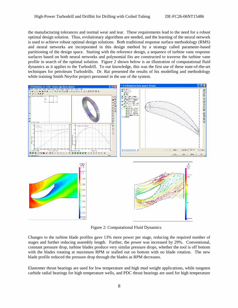
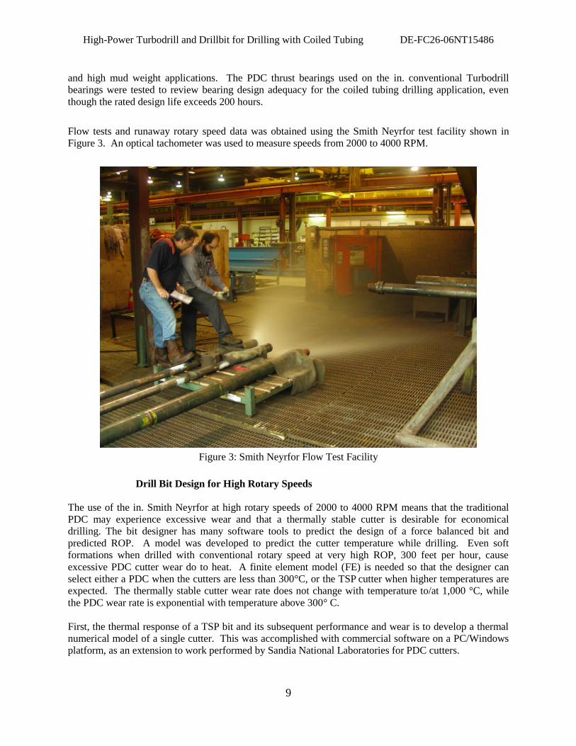
Flow tests and runaway rotary speed data was obtained using the Smith Neyrfor test facility shown in
Figure 3. An optical tachometer was used to measure speeds from 2000 to 4000 RPM.
Figure 3: Smith Neyrfor Flow Test Facility
Drill Bit Design for High Rotary Speeds
The use of the in. Smith Neyrfor at high rotary speeds of 2000 to 4000 RPM means that the traditional
PDC may experience excessive wear and that a thermally stable cutter is desirable for economical
drilling. The bit designer has many software tools to predict the design of a force balanced bit and
predicted ROP. A model was developed to predict the cutter temperature while drilling. Even soft
formations when drilled with conventional rotary speed at very high ROP, 300 feet per hour, cause
excessive PDC cutter wear do to heat. A finite element model (FE) is needed so that the designer can
select either a PDC when the cutters are less than 300°C, or the TSP cutter when higher temperatures are
expected. The thermally stable cutter wear rate does not change with temperature to/at 1,000 °C, while
the PDC wear rate is exponential with temperature above 300° C.
First, the thermal response of a TSP bit and its subsequent performance and wear is to develop a thermal
numerical model of a single cutter. This was accomplished with commercial software on a PC/Windows
platform, as an extension to work performed by Sandia National Laboratories for PDC cutters.
High-Power Turbodrill and Drillbit for Drilling with Coiled Tubing DE-FC26-06NT15486
10
Three-dimensional models were developed for various wear conditions, ranging from sharp to severely
worn. Two dimensional models were used in previous work at Sandia National Laboratories.
Appropriate boundary conditions for such a model include frictional heating at the wearflat, convective
cooling along the TSP diamond face and sides of the cutter, and heat conduction into the body of the bit.
Appropriate values for all these conditions are known from previous work.
The output from such a model is the temperature field throughout the cutter. Of critical importance here
are the temperatures and thermal gradients along the TSP diamond face, at the diamond/cutter interface,
and along the cutter wearflat. These predictions allowed the thermal stresses throughout the cutter to be
estimated. In addition the mean temperature along the wearflat can be calculated, which leads to a single,
quantitative parameter known as the thermal response function. This parameter is basically the mean
temperature rise, per unit heat input, of the cutter wearflat above the ambient fluid temperature. It is a
function of the convective cooling rate and the cutter wear configuration.
The thermal response function can then be used in a classical analytical solution for a sliding heat source
along a semi-infinite slab, in this case the rock surface. This solution provides a partitioning of the
frictional heat between the cutter and the rock and is a function of the friction coefficient, the sliding
velocity, and the rock‟s thermal properties. Again, appropriate values for all these parameters are known
from previous work.
The result of this task was a model used to predict the mean wearflat and diamond-face temperatures of a
TSP cutter under a wide variety of conditions. The ability to predict these temperatures allowed the
severity of the frictional heating and the subsequent performance and wear of a single TSP cutter was
assessed for the wide range of conditions existing for a TSP cutter on a high-speed motor.
Then, the thermal model of the single TSP cutter was exercised to characterize the range of thermal
response expected of a given TSP cutter on a high-speed bit. Parameters such as cutter speed, weight-on-
cutter, drilling fluid cooling rates, and rock type was varied to predict the cutter wearflat and diamond-
face temperatures. These results provided valuable insight regarding the thermal effect of variables, some
of which can be controlled and some of which cannot be controlled.
For example, the velocity of a cutter at a given location on a bit turning at a specific rotary speed cannot
be changed; but the weight on that cutter can be controlled to a certain extent by providing additional
cutters at or near that radial location. This is the so-called cutter redundancy that is an important factor in
TSP and PDC bit design. Likewise, the thermal properties of a given rock type cannot be controlled; but
the cooling rate of a given cutter can be controlled to a large extent with proper hydraulic design of the
bit.
The PDCWEAR code developed by Sandia National Laboratories has been extensively used by the PDC
bit industry to guide the design and to predict the performance of their bits over the past two decades.
The code allows a designer to specify many bit design and operational parameters, such as the location of
cutters on the bit face, drilling fluid cooling rates, the bit rotary speed, rock characteristics, and the bit
penetration rate, among others.
Based on these inputs, the code predicts the individual cutter loads, temperatures, and wear rates, and it
integrates these across the bit face to predict total bit performance parameters such as weight-on-bit,
drilling torque, bit side loading, and bending moments. One of the unique features of this code is its
ability to determine the interaction of nearby cutters and the effect of this interaction on cutter loads and
wear rates.
High-Power Turbodrill and Drillbit for Drilling with Coiled Tubing DE-FC26-06NT15486
11
As the bit is run in virtual space, the individual cutter geometries are modified according to their predicted
wear rates, and the cutter and bit performance parameters are calculated again for the next specified
drilling interval. Virtual drilling thus proceeds until the bit is worn out, as indicated by any number of
cutter or bit performance thresholds. One such threshold is a cutter reaching its critical wearflat
temperature, where thermally accelerated wear occurs. Another threshold is reaching a maximum drilling
torque or weight-on bit based on practical drilling limitations.
The predicted performance of a given bit can then be compared with the predicted performance of
different bits or the same bit with design modifications. It is thus a relatively straightforward matter of
iterating toward an optimized bit design for a given rock type or rotary speed. PDC bit companies have
successfully used the code to balance their bits, provide appropriate cutter redundancy, and identify
potential design problems, to name a few uses, before actually building and running a physical bit.
Under this task, the PDCWEAR code was modified to accommodate the physical properties of TSP
cutters and named DragBit. It was modified as necessary to also run TSP bits on high-speed (up to 4,000
rpm) Turbodrills. The various algorithms used to calculate cutter temperatures, cutter interaction, wear
rates, and a variety of other phenomena modelled in the code was examined in detail. These algorithms
can be changed, where necessary, to account for any significant differences in cutter geometry, bit design
practices, or operating conditions posed by using TSP cutters instead of PDC cutters. Any changes thus
identified can be implemented in an incremental, methodical manner in order to assess and document the
effects of these changes on the performance of the code.
PDCWEAR has been updated so that it now deals better with bits that have multiple redundant cutters. It
took a relatively simple fix to the logic to enable the routine to work when very thin, vertical slices of
rock are cut by a multitude of gage cutters. This correlation provides a single equation that includes the
wearflat heat flux and the wearflat length. Because of the non-linearity of the numerical results and the
resulting correlation equation, the program required a routine that iterates on the cutter temperatures at
each step. The routine converges fairly rapidly, within 5-10 iterations, so it does not contribute
significantly to the program execution time.
Using the upgraded code, two runs of the 4-1/8 “fixed cutter bit were completed. Both runs simulate
drilling in Sierra White Granite with water-based mud cooling. The first run uses a bit rotary speed of
100 RPM and penetration rates of 10-50 ft/hr, with cutter wear calculations based on 30 ft/hr. The second
run uses a rotary speed of 2,200 RPM and penetration rates of 50-250 ft/hr, with wear calculations based
on 150 ft/hr.
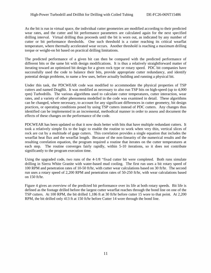
Figure 4 gives an overview of the predicted bit performance over its life at both rotary speeds. Bit life is
defined as the footage drilled before the largest cutter wearflat reaches through the bond line on one of the
TSP cutters. At 100 RPM, the bit drilled 1,186 ft at 30 ft/hr before cutter 15 wore to that point. At 2,200
RPM, the bit drilled only 413 ft at 150 ft/hr before Cutter 14 wore through the bond line.
High-Power Turbodrill and Drillbit for Drilling with Coiled Tubing DE-FC26-06NT15486
12
0
1,000
2,000
3,000
4,000
5,000
6,000
7,000
8,000
9,000
10,000
0 200 400 600 800 1000 1200 1400
WO
B (
lb)
at
Sp
ecif
ied
RO
P
Drilled Footage, ft
2200 RPM, 150 ft/hr100 RPM, 30 ft/hr
Figure 4: Effect of Weight-on-bit to Achieve Constant ROP as the Cutters Wear
Note that when sharp, the high-speed bit requires only about 20% as much weight-on-bit to drill 5 times
faster than the low-speed bit. To maintain that ROP advantage as the bit wears, however, the high-speed
bit eventually requires more WOB at a given drilled footage. This is because the cutters wear faster on a
per-foot basis with the high-speed conditions assumed in these runs.
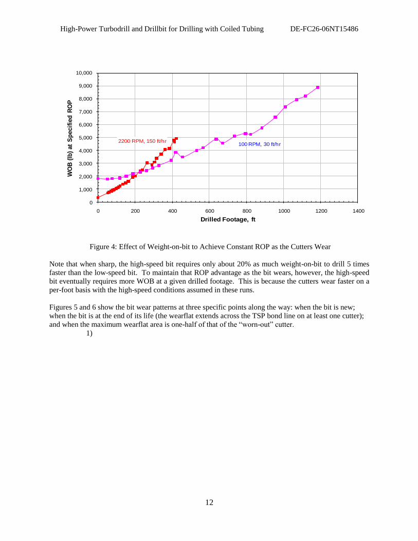
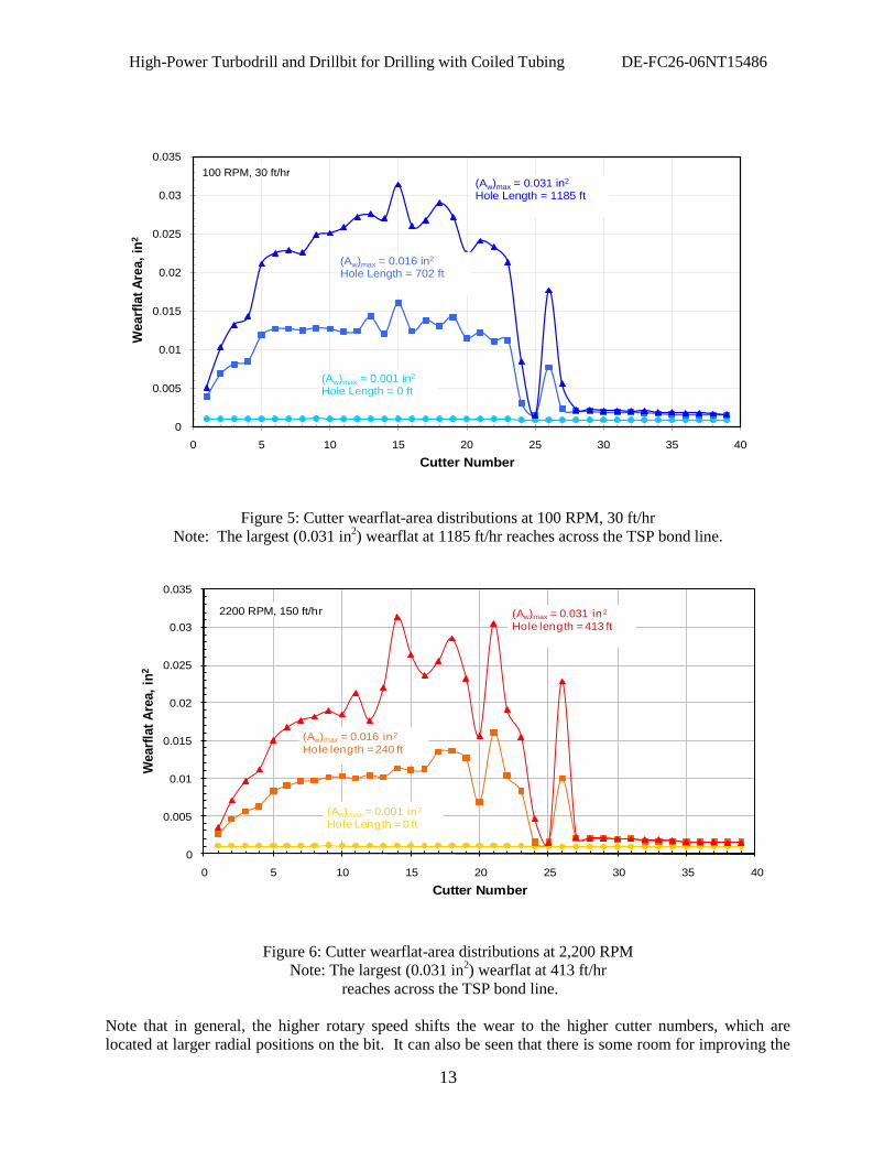
Figures 5 and 6 show the bit wear patterns at three specific points along the way: when the bit is new;
when the bit is at the end of its life (the wearflat extends across the TSP bond line on at least one cutter);
and when the maximum wearflat area is one-half of that of the “worn-out” cutter.
1)
High-Power Turbodrill and Drillbit for Drilling with Coiled Tubing DE-FC26-06NT15486
13
0
0.005
0.01
0.015
0.02
0.025
0.03
0.035
0 5 10 15 20 25 30 35 40
Wearf
lat
Are
a,
in2
Cutter Number
100 RPM, 30 ft/hr
(Aw)max = 0.001 in2
Hole Length = 0 ft
(Aw)max = 0.016 in2
Hole Length = 702 ft
(Aw)max = 0.031 in2
Hole Length = 1185 ft
Figure 5: Cutter wearflat-area distributions at 100 RPM, 30 ft/hr
Note: The largest (0.031 in2) wearflat at 1185 ft/hr reaches across the TSP bond line.
0
0.005
0.01
0.015
0.02
0.025
0.03
0.035
0 5 10 15 20 25 30 35 40
Wearf
lat
Are
a,
in2
Cutter Number
2200 RPM, 150 ft/hr
(Aw)max = 0.001 in2
Hole Length = 0 ft
(Aw)max = 0.016 in2
Hole length = 240 ft
(Aw)max = 0.031 in2
Hole length = 413 ft
Figure 6: Cutter wearflat-area distributions at 2,200 RPM
Note: The largest (0.031 in2) wearflat at 413 ft/hr
reaches across the TSP bond line.
Note that in general, the higher rotary speed shifts the wear to the higher cutter numbers, which are
located at larger radial positions on the bit. It can also be seen that there is some room for improving the
High-Power Turbodrill and Drillbit for Drilling with Coiled Tubing DE-FC26-06NT15486
14
wear pattern of the bit at both speeds because some cutters experience much higher wear than some of the
surrounding cutters. Slightly changing the radial and circumferential positions of these cutters could
spread the wear more evenly and increase the bit life at both rotary speeds.
The cutter wear model used to calculate these wear patterns assumes the volumetric cutter wear per length
of hole drilled to be directly proportional to the cutter penetrating force and radial position on the cutter
and inversely proportional to the bit feed rate (inches/revolution). This model does not include any
temperature effects, primarily because we had so little quantitative data available in 1986. We knew that
wear rates for conventional PDC cutters at that time increased by about an order of magnitude when
cutter temperatures exceeded about 350oC, so PDCWEAR was set up to raise a flag when any cutter
temperature exceeds that level. At conventional rotary speeds, that level is usually attained only when
one or more cutters become very worn, so the usual interpretation of the flag is as a sign that the bit is
worn out. As a practical matter, once thermally accelerated wear begins, there is little additional bit life
left anyway.
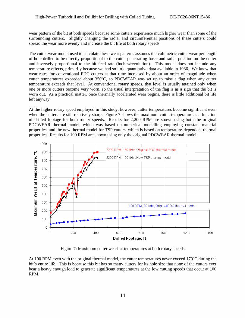
At the higher rotary speed employed in this study, however, cutter temperatures become significant even
when the cutters are still relatively sharp. Figure 7 shows the maximum cutter temperature as a function
of drilled footage for both rotary speeds. Results for 2,200 RPM are shown using both the original
PDCWEAR thermal model, which was based on numerical modelling employing constant material
properties, and the new thermal model for TSP cutters, which is based on temperature-dependent thermal
properties. Results for 100 RPM are shown using only the original PDCWEAR thermal model.
Figure 7: Maximum cutter wearflat temperatures at both rotary speeds
At 100 RPM even with the original thermal model, the cutter temperatures never exceed 170oC during the
bit‟s entire life. This is because this bit has so many cutters for its hole size that none of the cutters ever
bear a heavy enough load to generate significant temperatures at the low cutting speeds that occur at 100
RPM.
High-Power Turbodrill and Drillbit for Drilling with Coiled Tubing DE-FC26-06NT15486
15
At 2,200 RPM, however, the maximum cutter temperature exceeds 350oC after 104 ft of drilling. It
exceeds 600oC after about 260 ft of drilling and reaches 830
oC before the end of the bit‟s life (at 413 ft
based on non-thermal abrasive wear). Note that the new TSP thermal model predicts lower temperatures
than the original PDC thermal model. Although the results for the new temperature-dependent PDC
numerical modelling have not yet been incorporated into PDCWEAR, those results indicate that the
predicted PDC cutter temperatures would be higher than those predicted by the original PDC thermal
model. The difference in thermal performance between TSP and PDC cutters, therefore, showed up as
very significant when this graph is re-drawn with the updated PDC thermal model predictions.
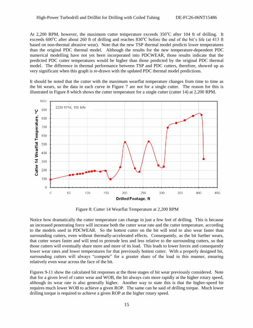
It should be noted that the cutter with the maximum wearflat temperature changes from time to time as
the bit wears, so the data in each curve in Figure 7 are not for a single cutter. The reason for this is
illustrated in Figure 8 which shows the cutter temperature for a single cutter (cutter 14) at 2,200 RPM.
Figure 8: Cutter 14 Wearflat Temperature at 2,200 RPM
Notice how dramatically the cutter temperature can change in just a few feet of drilling. This is because
an increased penetrating force will increase both the cutter wear rate and the cutter temperature, according
to the models used in PDCWEAR. So the hottest cutter on the bit will tend to also wear faster than
surrounding cutters, even without thermally-accelerated effects. Consequently, as the bit further wears,
that cutter wears faster and will tend to protrude less and less relative to the surrounding cutters, so that
those cutters will eventually share more and more of its load. This leads to lower forces and consequently
lower wear rates and lower temperatures for that previously hottest cutter. With a properly designed bit,
surrounding cutters will always “compete” for a greater share of the load in this manner, ensuring
relatively even wear across the face of the bit.
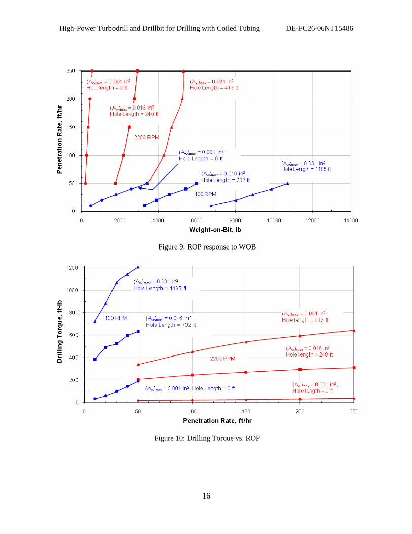
Figures 9-11 show the calculated bit responses at the three stages of bit wear previously considered. Note
that for a given level of cutter wear and WOB, the bit always cuts more rapidly at the higher rotary speed,
although its wear rate is also generally higher. Another way to state this is that the higher-speed bit
requires much lower WOB to achieve a given ROP. The same can be said of drilling torque. Much lower
drilling torque is required to achieve a given ROP at the higher rotary speed.
High-Power Turbodrill and Drillbit for Drilling with Coiled Tubing DE-FC26-06NT15486
16
Figure 9: ROP response to WOB
Figure 10: Drilling Torque vs. ROP
High-Power Turbodrill and Drillbit for Drilling with Coiled Tubing DE-FC26-06NT15486
17
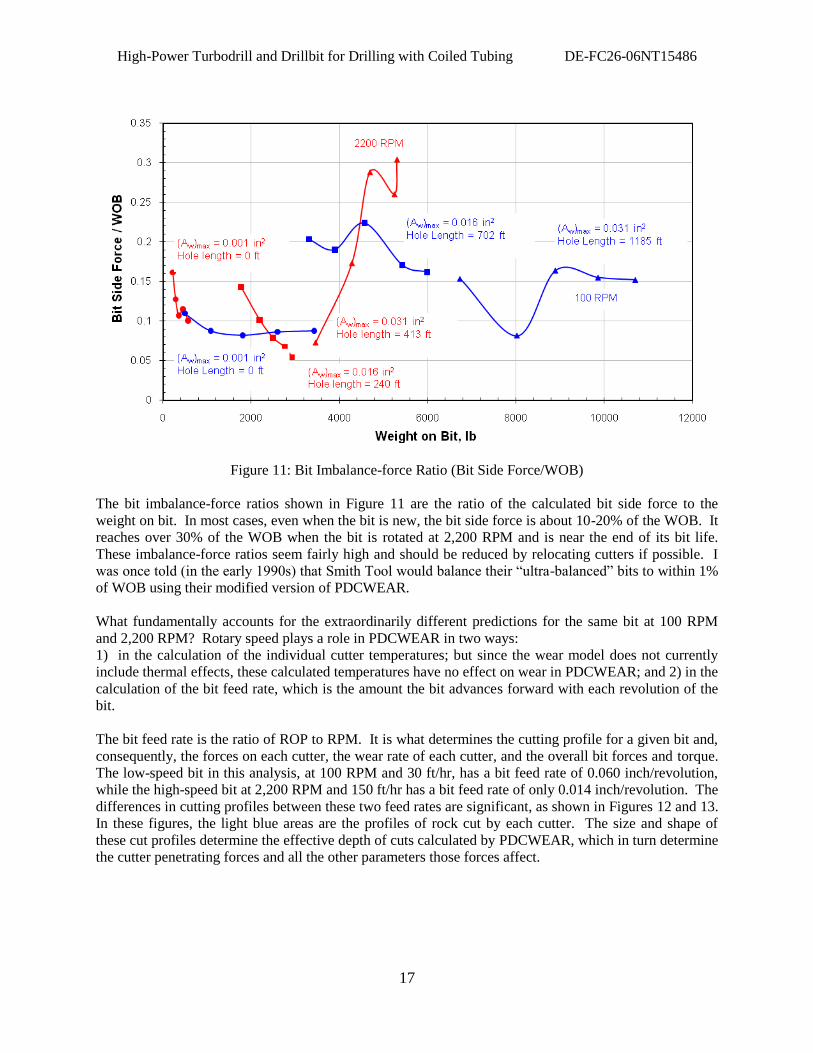
Figure 11: Bit Imbalance-force Ratio (Bit Side Force/WOB)
The bit imbalance-force ratios shown in Figure 11 are the ratio of the calculated bit side force to the
weight on bit. In most cases, even when the bit is new, the bit side force is about 10-20% of the WOB. It
reaches over 30% of the WOB when the bit is rotated at 2,200 RPM and is near the end of its bit life.
These imbalance-force ratios seem fairly high and should be reduced by relocating cutters if possible. I
was once told (in the early 1990s) that Smith Tool would balance their “ultra-balanced” bits to within 1%
of WOB using their modified version of PDCWEAR.
What fundamentally accounts for the extraordinarily different predictions for the same bit at 100 RPM
and 2,200 RPM? Rotary speed plays a role in PDCWEAR in two ways:
1) in the calculation of the individual cutter temperatures; but since the wear model does not currently
include thermal effects, these calculated temperatures have no effect on wear in PDCWEAR; and 2) in the
calculation of the bit feed rate, which is the amount the bit advances forward with each revolution of the
bit.
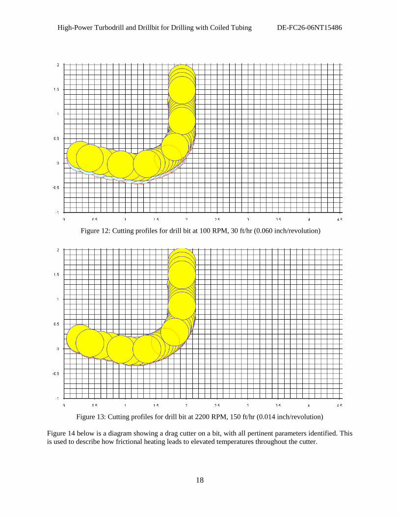
The bit feed rate is the ratio of ROP to RPM. It is what determines the cutting profile for a given bit and,
consequently, the forces on each cutter, the wear rate of each cutter, and the overall bit forces and torque.
The low-speed bit in this analysis, at 100 RPM and 30 ft/hr, has a bit feed rate of 0.060 inch/revolution,
while the high-speed bit at 2,200 RPM and 150 ft/hr has a bit feed rate of only 0.014 inch/revolution. The
differences in cutting profiles between these two feed rates are significant, as shown in Figures 12 and 13.
In these figures, the light blue areas are the profiles of rock cut by each cutter. The size and shape of
these cut profiles determine the effective depth of cuts calculated by PDCWEAR, which in turn determine
the cutter penetrating forces and all the other parameters those forces affect.
High-Power Turbodrill and Drillbit for Drilling with Coiled Tubing DE-FC26-06NT15486
18
Figure 12: Cutting profiles for drill bit at 100 RPM, 30 ft/hr (0.060 inch/revolution)
Figure 13: Cutting profiles for drill bit at 2200 RPM, 150 ft/hr (0.014 inch/revolution)
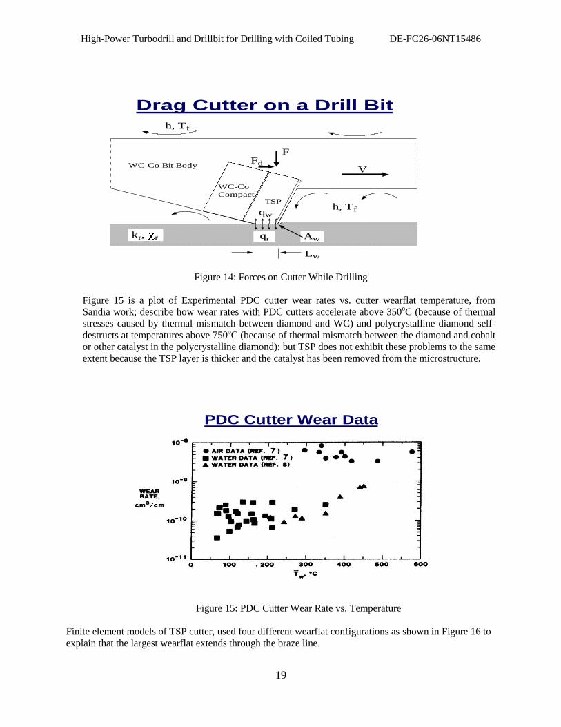
Figure 14 below is a diagram showing a drag cutter on a bit, with all pertinent parameters identified. This
is used to describe how frictional heating leads to elevated temperatures throughout the cutter.
High-Power Turbodrill and Drillbit for Drilling with Coiled Tubing DE-FC26-06NT15486
19
Drag Cutter on a Drill Bit
h, Tf
FFd
V
qw
qrkr, r Aw
Lw
h, Tf
TSP
WC-Co
Compact
WC-Co Bit Body
Figure 14: Forces on Cutter While Drilling
Figure 15 is a plot of Experimental PDC cutter wear rates vs. cutter wearflat temperature, from
Sandia work; describe how wear rates with PDC cutters accelerate above 350oC (because of thermal
stresses caused by thermal mismatch between diamond and WC) and polycrystalline diamond self-
destructs at temperatures above 750oC (because of thermal mismatch between the diamond and cobalt
or other catalyst in the polycrystalline diamond); but TSP does not exhibit these problems to the same
extent because the TSP layer is thicker and the catalyst has been removed from the microstructure.
PDC Cutter Wear Data
Figure 15: PDC Cutter Wear Rate vs. Temperature
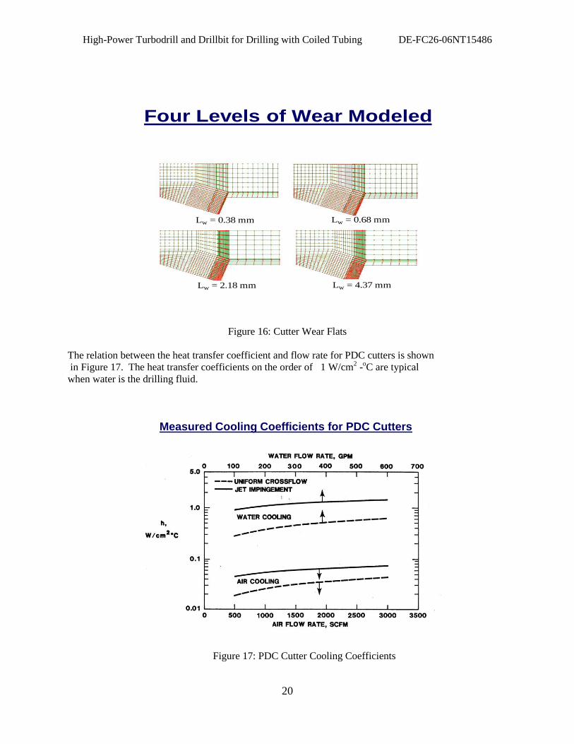
Finite element models of TSP cutter, used four different wearflat configurations as shown in Figure 16 to
explain that the largest wearflat extends through the braze line.
High-Power Turbodrill and Drillbit for Drilling with Coiled Tubing DE-FC26-06NT15486
20
Four Levels of Wear Modeled
Lw = 0.38 mm Lw = 0.68 mm
Lw = 2.18 mm Lw = 4.37 mm
Figure 16: Cutter Wear Flats
The relation between the heat transfer coefficient and flow rate for PDC cutters is shown
in Figure 17. The heat transfer coefficients on the order of 1 W/cm2 -
oC are typical
when water is the drilling fluid.
Measured Cooling Coefficients for PDC Cutters
Figure 17: PDC Cutter Cooling Coefficients
High-Power Turbodrill and Drillbit for Drilling with Coiled Tubing DE-FC26-06NT15486
21
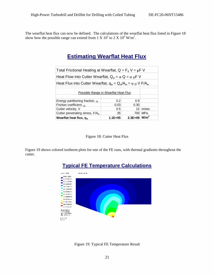
The wearflat heat flux can now be defined. The calculations of the wearflat heat flux listed in Figure 18
show how the possible range can extend from 1 X 10⁵ to 2 X 10
9 W/m
2.
Estimating Wearflat Heat Flux
Total Frictional Heating at Wearflat, Q = Fd V = F V
Heat Flow into Cutter Wearflat, Qw = Q = F V
Heat Flux into Cutter Wearflat, qw = Qw/Aw = V F/Aw
Possible Range in Wearflat Heat Flux
Energy partitioning fraction, 0.2 0.9
Friction coefficient, 0.03 0.30
Cutter velocity, V 0.5 12 m/sec
Cutter penetrating stress, F/Aw 35 700 MPa
Wearflat heat flux, qw 1.1E+05 2.3E+09 W/m2
Figure 18: Cutter Heat Flux
Figure 19 shows colored isotherm plots for one of the FE runs, with thermal gradients throughout the
cutter.
Typical FE Temperature Calculations
Figure 19: Typical FE Temperature Result
High-Power Turbodrill and Drillbit for Drilling with Coiled Tubing DE-FC26-06NT15486
22
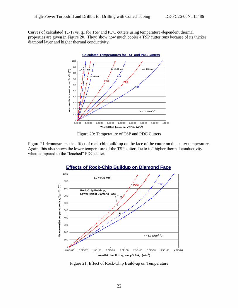
Curves of calculated Tw-Tf vs. qw for TSP and PDC cutters using temperature-dependent thermal
properties are given in Figure 20. They; show how much cooler a TSP cutter runs because of its thicker
diamond layer and higher thermal conductivity.
Calculated Temperatures for TSP and PDC Cutters
0
100
200
300
400
500
600
700
800
900
1000
0.0E+00 5.0E+07 1.0E+08 1.5E+08 2.0E+08 2.5E+08 3.0E+08 3.5E+08 4.0E+08
Wearflat Heat flux, qw = V F/Aw (W/m2)
Me
an
we
arf
lat
tem
pe
ratu
re r
ise
, T
w -
Tf (
oC
) Lw = 0.38 mmLw = 0.68 mm
Lw = 2.19 mm
TSP
TSP
PDCPDC
Lw = 4.37 mm
h = 1.0 W/cm2-oC
Figure 20: Temperature of TSP and PDC Cutters
Figure 21 demonstrates the affect of rock-chip build-up on the face of the cutter on the cutter temperature.
Again, this also shows the lower temperature of the TSP cutter due to its‟ higher thermal conductivity
when compared to the “leached” PDC cutter.
Effects of Rock-Chip Buildup on Diamond Face
0
100
200
300
400
500
600
700
800
900
1000
0.0E+00 5.0E+07 1.0E+08 1.5E+08 2.0E+08 2.5E+08 3.0E+08 3.5E+08 4.0E+08
Wearflat Heat flux, qw = V F/Aw (W/m2)
Me
an
we
arf
lat
tem
pe
ratu
re r
ise
, T
w -
Tf (
oC
)
Lw = 0.38 mm
TSPPDC
Rock-Chip Build-up,
Lower Half of Diamond Face
h = 1.0 W/cm2-oC
Figure 21: Effect of Rock-Chip Build-up on Temperature
High-Power Turbodrill and Drillbit for Drilling with Coiled Tubing DE-FC26-06NT15486
23
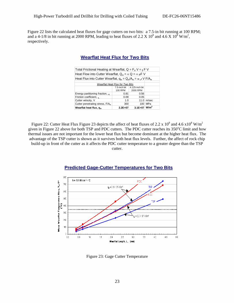
Figure 22 lists the calculated heat fluxes for gage cutters on two bits: a 7.5-in bit running at 100 RPM;
and a 4-1/8 in bit running at 2000 RPM, leading to heat fluxes of 2.2 X 10⁸ and 4.6 X 10
8 W/m
2,
respectively.
Wearflat Heat Flux for Two Bits
Total Frictional Heating at Wearflat, Q = Fd V = F V
Heat Flow into Cutter Wearflat, Qw = Q = F V
Heat Flux into Cutter Wearflat, qw = Qw/Aw = V F/Aw
Wearflat Heat Flux for Two Bits7.5-inch bit
100 RPM
4.125-inch bit
2000 RPM
Energy partitioning fraction, 0.81 0.56
Friction coefficient, 0.09 0.05
Cutter velocity, V 1.0 11.0 m/sec
Cutter penetrating stress, F/Aw 300 100 MPa
Wearflat heat flux, qw 2.2E+07 3.1E+07 W/m2
Figure 22: Cutter Heat Flux Figure 23 depicts the affect of heat fluxes of 2.2 x 10
8 and 4.6 x10
8 W/m
2
given in Figure 22 above for both TSP and PDC cutters. The PDC cutter reaches its 350oC limit and how
thermal issues are not important for the lower heat flux but become dominant at the higher heat flux. The
advantage of the TSP cutter is shown as it survives both heat flux levels. Further, the affect of rock chip
build-up in front of the cutter as it affects the PDC cutter temperature to a greater degree than the TSP
cutter.
Predicted Gage-Cutter Temperatures for Two Bits
Figure 23: Gage Cutter Temperature
High-Power Turbodrill and Drillbit for Drilling with Coiled Tubing DE-FC26-06NT15486
24
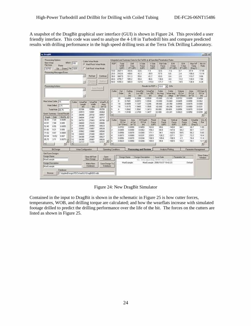
A snapshot of the DragBit graphical user interface (GUI) is shown in Figure 24. This provided a user
friendly interface. This code was used to analyze the 4-1/8 in Turbodrill bits and compare predicted
results with drilling performance in the high speed drilling tests at the Terra Tek Drilling Laboratory.
Figure 24: New DragBit Simulator
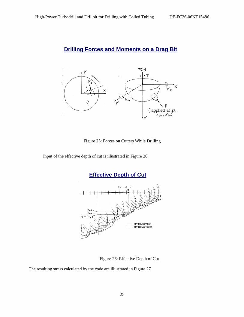
Contained in the input to DragBit is shown in the schematic in Figure 25 is how cutter forces,
temperatures, WOB, and drilling torque are calculated; and how the wearflats increase with simulated
footage drilled to predict the drilling performance over the life of the bit. The forces on the cutters are
listed as shown in Figure 25.
High-Power Turbodrill and Drillbit for Drilling with Coiled Tubing DE-FC26-06NT15486
25
Drilling Forces and Moments on a Drag Bit
Figure 25: Forces on Cutters While Drilling
Input of the effective depth of cut is illustrated in Figure 26.
Effective Depth of Cut
Figure 26: Effective Depth of Cut
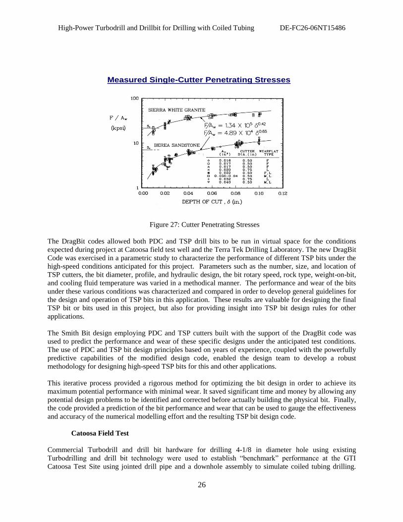
The resulting stress calculated by the code are illustrated in Figure 27
High-Power Turbodrill and Drillbit for Drilling with Coiled Tubing DE-FC26-06NT15486
26
Measured Single-Cutter Penetrating Stresses
Figure 27: Cutter Penetrating Stresses
The DragBit codes allowed both PDC and TSP drill bits to be run in virtual space for the conditions
expected during project at Catoosa field test well and the Terra Tek Drilling Laboratory. The new DragBit
Code was exercised in a parametric study to characterize the performance of different TSP bits under the
high-speed conditions anticipated for this project. Parameters such as the number, size, and location of
TSP cutters, the bit diameter, profile, and hydraulic design, the bit rotary speed, rock type, weight-on-bit,
and cooling fluid temperature was varied in a methodical manner. The performance and wear of the bits
under these various conditions was characterized and compared in order to develop general guidelines for
the design and operation of TSP bits in this application. These results are valuable for designing the final
TSP bit or bits used in this project, but also for providing insight into TSP bit design rules for other
applications.
The Smith Bit design employing PDC and TSP cutters built with the support of the DragBit code was
used to predict the performance and wear of these specific designs under the anticipated test conditions.
The use of PDC and TSP bit design principles based on years of experience, coupled with the powerfully
predictive capabilities of the modified design code, enabled the design team to develop a robust
methodology for designing high-speed TSP bits for this and other applications.
This iterative process provided a rigorous method for optimizing the bit design in order to achieve its
maximum potential performance with minimal wear. It saved significant time and money by allowing any
potential design problems to be identified and corrected before actually building the physical bit. Finally,
the code provided a prediction of the bit performance and wear that can be used to gauge the effectiveness
and accuracy of the numerical modelling effort and the resulting TSP bit design code.
Catoosa Field Test
Commercial Turbodrill and drill bit hardware for drilling 4-1/8 in diameter hole using existing
Turbodrilling and drill bit technology were used to establish “benchmark” performance at the GTI
Catoosa Test Site using jointed drill pipe and a downhole assembly to simulate coiled tubing drilling.
High-Power Turbodrill and Drillbit for Drilling with Coiled Tubing DE-FC26-06NT15486
27
The downhole assembly included a commercial Smith Neyrfor 2-7/8 in directional Turbodrill and an
“aggressive” Smith 4-1/8 in fixed cutter drill bit specifically designed with TSP cutters for coiled tubing
drilling. The Turbodrill section for the baseline case rotated at 1,100 to 2,000 RPM depending on mud
weight, pressure drop, and flow rate.
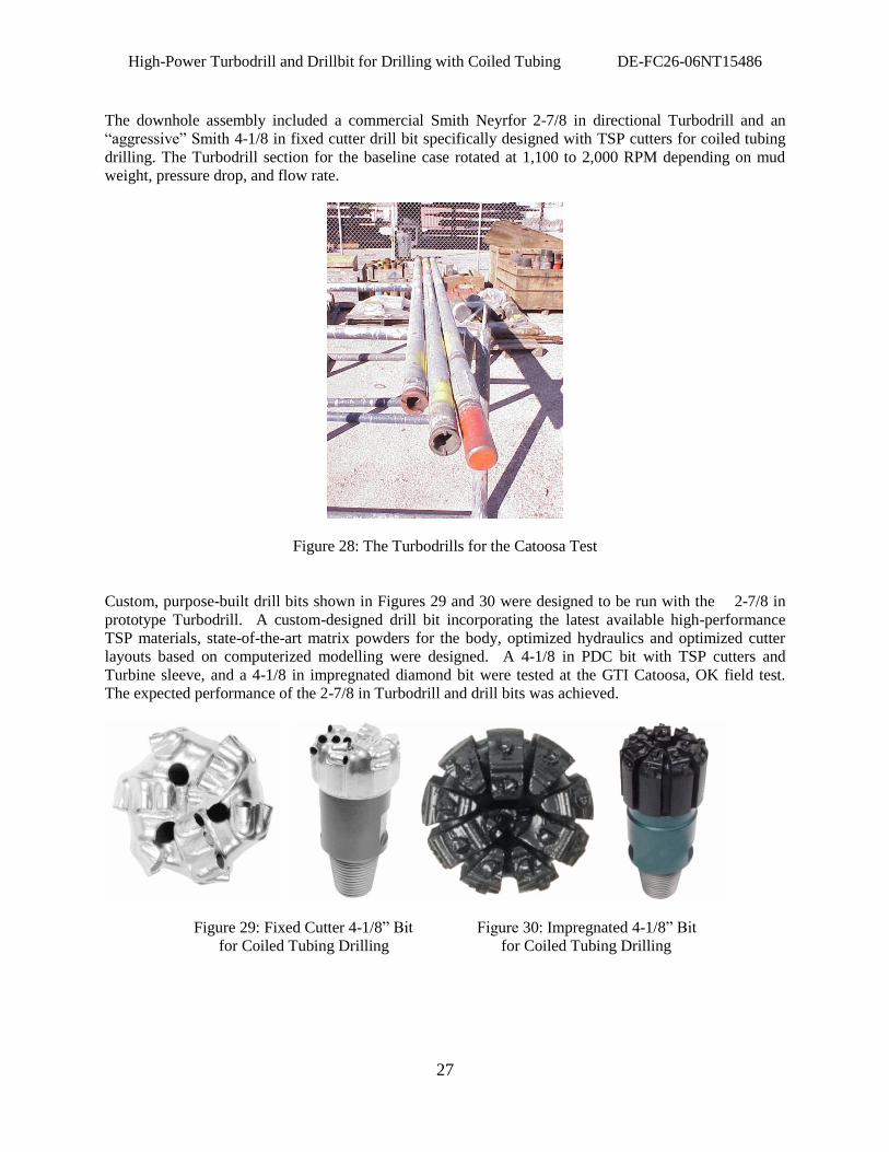
Figure 28: The Turbodrills for the Catoosa Test
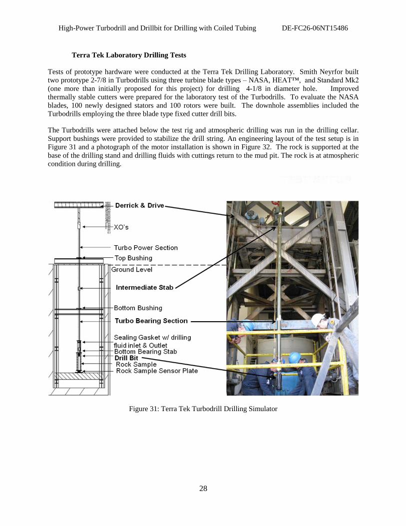
Custom, purpose-built drill bits shown in Figures 29 and 30 were designed to be run with the 2-7/8 in
prototype Turbodrill. A custom-designed drill bit incorporating the latest available high-performance
TSP materials, state-of-the-art matrix powders for the body, optimized hydraulics and optimized cutter
layouts based on computerized modelling were designed. A 4-1/8 in PDC bit with TSP cutters and
Turbine sleeve, and a 4-1/8 in impregnated diamond bit were tested at the GTI Catoosa, OK field test.
The expected performance of the 2-7/8 in Turbodrill and drill bits was achieved.
Figure 29: Fixed Cutter 4-1/8” Bit Figure 30: Impregnated 4-1/8” Bit
for Coiled Tubing Drilling for Coiled Tubing Drilling
High-Power Turbodrill and Drillbit for Drilling with Coiled Tubing DE-FC26-06NT15486
28
Terra Tek Laboratory Drilling Tests
Tests of prototype hardware were conducted at the Terra Tek Drilling Laboratory. Smith Neyrfor built
two prototype 2-7/8 in Turbodrills using three turbine blade types – NASA, HEAT™, and Standard Mk2
(one more than initially proposed for this project) for drilling 4-1/8 in diameter hole. Improved
thermally stable cutters were prepared for the laboratory test of the Turbodrills. To evaluate the NASA
blades, 100 newly designed stators and 100 rotors were built. The downhole assemblies included the
Turbodrills employing the three blade type fixed cutter drill bits.
The Turbodrills were attached below the test rig and atmospheric drilling was run in the drilling cellar.
Support bushings were provided to stabilize the drill string. An engineering layout of the test setup is in
Figure 31 and a photograph of the motor installation is shown in Figure 32. The rock is supported at the
base of the drilling stand and drilling fluids with cuttings return to the mud pit. The rock is at atmospheric
condition during drilling.
Figure 31: Terra Tek Turbodrill Drilling Simulator
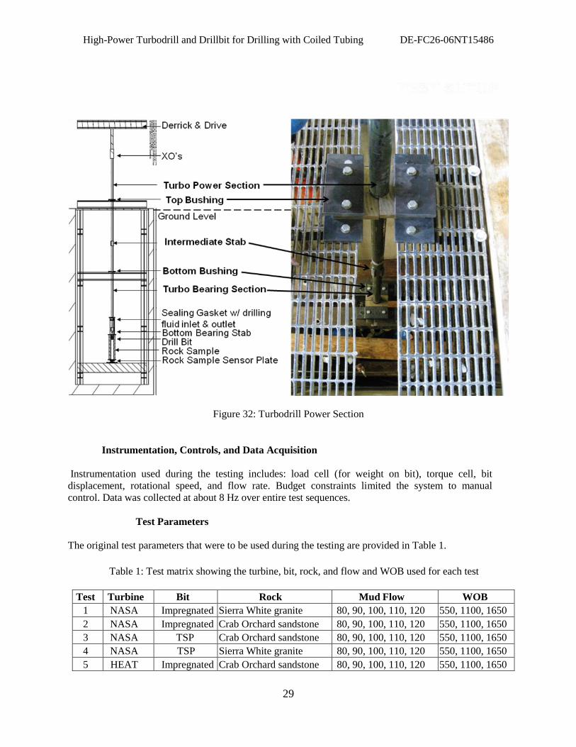
High-Power Turbodrill and Drillbit for Drilling with Coiled Tubing DE-FC26-06NT15486
29
Figure 32: Turbodrill Power Section
Instrumentation, Controls, and Data Acquisition
Instrumentation used during the testing includes: load cell (for weight on bit), torque cell, bit
displacement, rotational speed, and flow rate. Budget constraints limited the system to manual
control. Data was collected at about 8 Hz over entire test sequences.
Test Parameters
The original test parameters that were to be used during the testing are provided in Table 1.
Table 1: Test matrix showing the turbine, bit, rock, and flow and WOB used for each test
Test Turbine Bit Rock Mud Flow WOB
1 NASA Impregnated Sierra White granite 80, 90, 100, 110, 120 550, 1100, 1650
2 NASA Impregnated Crab Orchard sandstone 80, 90, 100, 110, 120 550, 1100, 1650
3 NASA TSP
C
Crab Orchard sandstone 80, 90, 100, 110, 120 550, 1100, 1650
4 NASA TSP Sierra White granite 80, 90, 100, 110, 120 550, 1100, 1650
5 HEAT Impregnated Crab Orchard sandstone 80, 90, 100, 110, 120 550, 1100, 1650
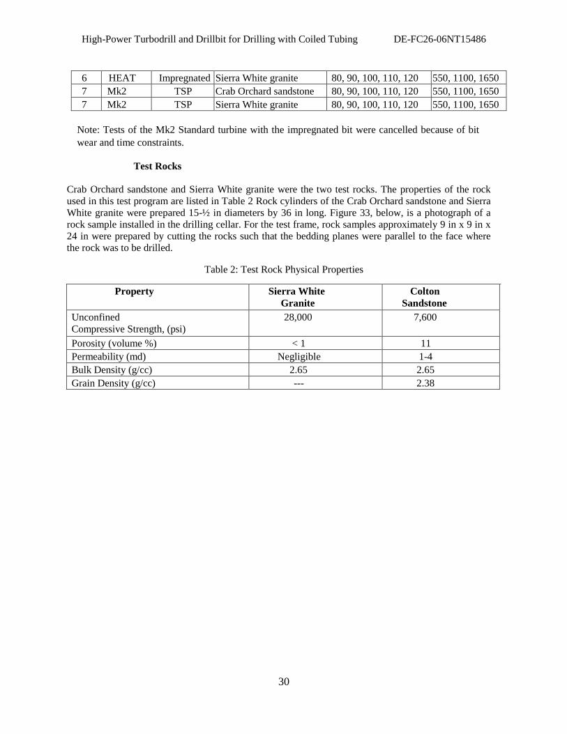
High-Power Turbodrill and Drillbit for Drilling with Coiled Tubing DE-FC26-06NT15486
30
6 HEAT Impregnated Sierra White granite 80, 90, 100, 110, 120 550, 1100, 1650
7 Mk2 TSP Crab Orchard sandstone 80, 90, 100, 110, 120 550, 1100, 1650
7 Mk2 TSP Sierra White granite 80, 90, 100, 110, 120 550, 1100, 1650
Note: Tests of the Mk2 Standard turbine with the impregnated bit were cancelled because of bit
wear and time constraints.
Test Rocks
Crab Orchard sandstone and Sierra White granite were the two test rocks. The properties of the rock
used in this test program are listed in Table 2 Rock cylinders of the Crab Orchard sandstone and Sierra
White granite were prepared 15-½ in diameters by 36 in long. Figure 33, below, is a photograph of a
rock sample installed in the drilling cellar. For the test frame, rock samples approximately 9 in x 9 in x
24 in were prepared by cutting the rocks such that the bedding planes were parallel to the face where
the rock was to be drilled.
Table 2: Test Rock Physical Properties
Property Sierra White
Granite
Colton
Sandstone
Unconfined
Compressive Strength, (psi)
28,000 7,600
Porosity (volume %) < 1 11
Permeability (md) Negligible 1-4
Bulk Density (g/cc) 2.65 2.65
Grain Density (g/cc) --- 2.38
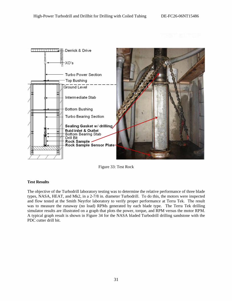
High-Power Turbodrill and Drillbit for Drilling with Coiled Tubing DE-FC26-06NT15486
31
Figure 33: Test Rock
Test Results
The objective of the Turbodrill laboratory testing was to determine the relative performance of three blade
types, NASA, HEAT, and Mk2, in a 2-7/8 in. diameter Turbodrill. To do this, the motors were inspected
and flow tested at the Smith Neyrfor laboratory to verify proper performance at Terra Tek. The result
was to measure the runaway (no load) RPMs generated by each blade type. The Terra Tek drilling
simulator results are illustrated on a graph that plots the power, torque, and RPM versus the motor RPM.
A typical graph result is shown in Figure 34 for the NASA bladed Turbodrill drilling sandstone with the
PDC cutter drill bit.
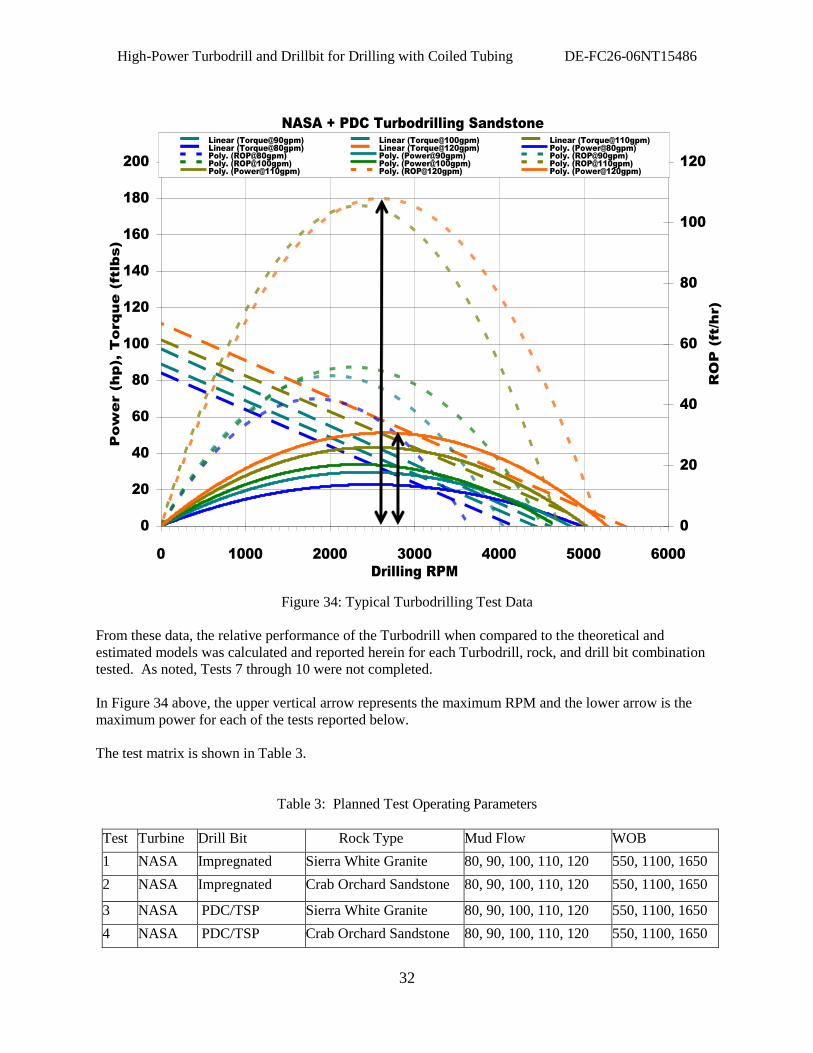
High-Power Turbodrill and Drillbit for Drilling with Coiled Tubing DE-FC26-06NT15486
32
NASA + PDC Turbodrilling Sandstone
0
20
40
60
80
100
120
140
160
180
200
0 1000 2000 3000 4000 5000 6000
Drilling RPM
Pow
er (hp), T
orque (ftlbs)
0
20
40
60
80
100
120
RO
P (ft/hr)
Linear (Torque@90gpm) Linear (Torque@100gpm) Linear (Torque@110gpm)
Linear (Torque@80gpm) Linear (Torque@120gpm) Poly. (Power@80gpm)
Poly. (ROP@80gpm) Poly. (Power@90gpm) Poly. (ROP@90gpm)
Poly. (ROP@100gpm) Poly. (Power@100gpm) Poly. (ROP@110gpm)
Poly. (Power@110gpm) Poly. (ROP@120gpm) Poly. (Power@120gpm)
Figure 34: Typical Turbodrilling Test Data
From these data, the relative performance of the Turbodrill when compared to the theoretical and
estimated models was calculated and reported herein for each Turbodrill, rock, and drill bit combination
tested. As noted, Tests 7 through 10 were not completed.
In Figure 34 above, the upper vertical arrow represents the maximum RPM and the lower arrow is the
maximum power for each of the tests reported below.
The test matrix is shown in Table 3.
Table 3: Planned Test Operating Parameters
Test Turbine Drill Bit Rock Type Mud Flow WOB
1 NASA Impregnated Sierra White Granite 80, 90, 100, 110, 120 550, 1100, 1650
2 NASA Impregnated Crab Orchard Sandstone 80, 90, 100, 110, 120 550, 1100, 1650
3 NASA PDC/TSP Sierra White Granite 80, 90, 100, 110, 120 550, 1100, 1650
4 NASA PDC/TSP Crab Orchard Sandstone 80, 90, 100, 110, 120 550, 1100, 1650
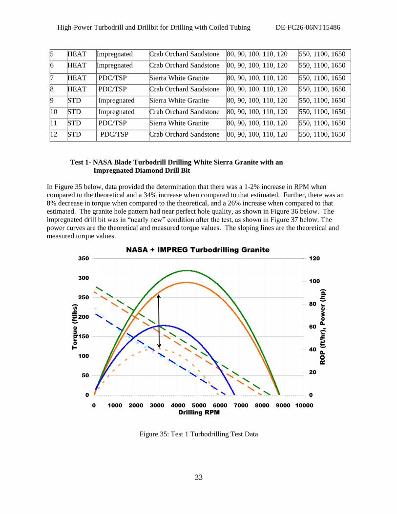
High-Power Turbodrill and Drillbit for Drilling with Coiled Tubing DE-FC26-06NT15486
33
5 HEAT Impregnated Crab Orchard Sandstone 80, 90, 100, 110, 120 550, 1100, 1650
6 HEAT Impregnated Crab Orchard Sandstone 80, 90, 100, 110, 120 550, 1100, 1650
7 HEAT PDC/TSP Sierra White Granite 80, 90, 100, 110, 120 550, 1100, 1650
8 HEAT PDC/TSP Crab Orchard Sandstone 80, 90, 100, 110, 120 550, 1100, 1650
9 STD Impregnated Sierra White Granite 80, 90, 100, 110, 120 550, 1100, 1650
10 STD Impregnated Crab Orchard Sandstone 80, 90, 100, 110, 120 550, 1100, 1650
11 STD PDC/TSP Sierra White Granite 80, 90, 100, 110, 120 550, 1100, 1650
12 STD PDC/TSP Crab Orchard Sandstone 80, 90, 100, 110, 120 550, 1100, 1650
Test 1- NASA Blade Turbodrill Drilling White Sierra Granite with an
Impregnated Diamond Drill Bit
In Figure 35 below, data provided the determination that there was a 1-2% increase in RPM when
compared to the theoretical and a 34% increase when compared to that estimated. Further, there was an
8% decrease in torque when compared to the theoretical, and a 26% increase when compared to that
estimated. The granite hole pattern had near perfect hole quality, as shown in Figure 36 below. The
impregnated drill bit was in “nearly new” condition after the test, as shown in Figure 37 below. The
power curves are the theoretical and measured torque values. The sloping lines are the theoretical and
measured torque values.
NASA + IMPREG Turbodrilling Granite
0
50
100
150
200
250
300
350
0 1000 2000 3000 4000 5000 6000 7000 8000 9000 10000
Drilling RPM
To
rq
ue
(ftlb
s)
0
20
40
60
80
100
120
RO
P (ft/h
r), P
ow
er (h
p)
Figure 35: Test 1 Turbodrilling Test Data
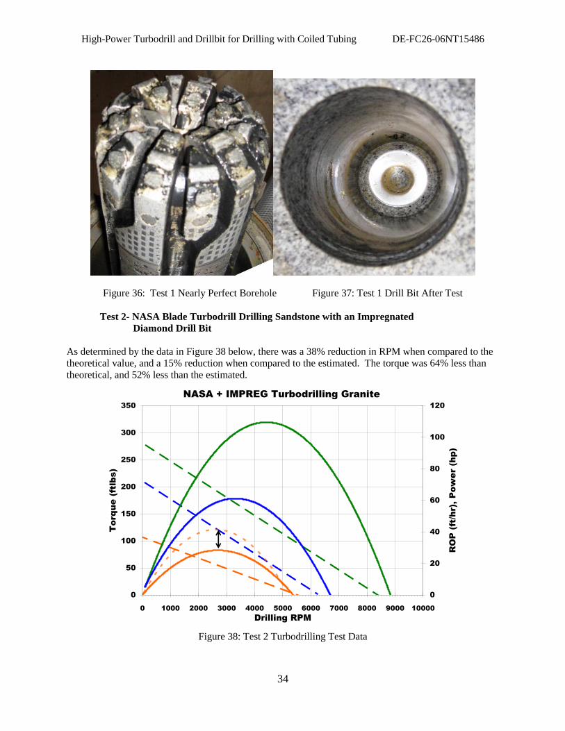
High-Power Turbodrill and Drillbit for Drilling with Coiled Tubing DE-FC26-06NT15486
34
Figure 36: Test 1 Nearly Perfect Borehole Figure 37: Test 1 Drill Bit After Test
Test 2- NASA Blade Turbodrill Drilling Sandstone with an Impregnated
Diamond Drill Bit
As determined by the data in Figure 38 below, there was a 38% reduction in RPM when compared to the
theoretical value, and a 15% reduction when compared to the estimated. The torque was 64% less than
theoretical, and 52% less than the estimated.
NASA + IMPREG Turbodrilling Granite
0
50
100
150
200
250
300
350
0 1000 2000 3000 4000 5000 6000 7000 8000 9000 10000
Drilling RPM
To
rq
ue
(ftlb
s)
0
20
40
60
80
100
120
RO
P (ft/h
r), P
ow
er (h
p)
Figure 38: Test 2 Turbodrilling Test Data
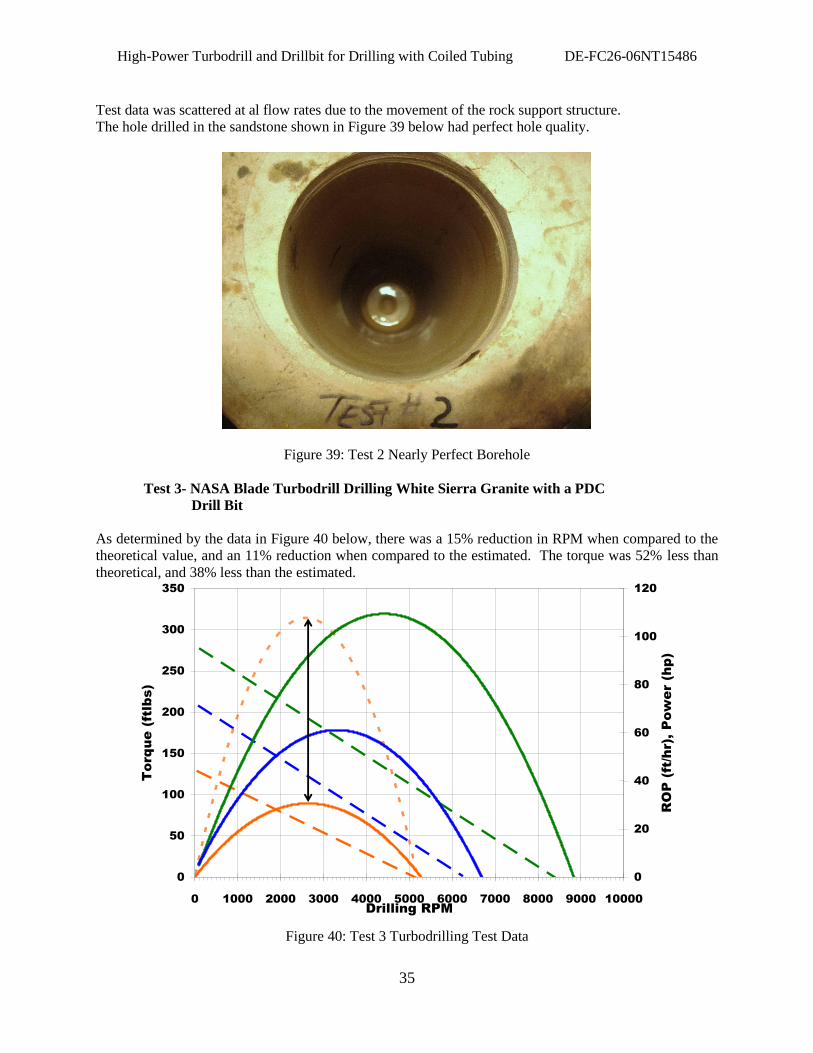
High-Power Turbodrill and Drillbit for Drilling with Coiled Tubing DE-FC26-06NT15486
35
Test data was scattered at al flow rates due to the movement of the rock support structure.
The hole drilled in the sandstone shown in Figure 39 below had perfect hole quality.
Figure 39: Test 2 Nearly Perfect Borehole
Test 3- NASA Blade Turbodrill Drilling White Sierra Granite with a PDC
Drill Bit
As determined by the data in Figure 40 below, there was a 15% reduction in RPM when compared to the
theoretical value, and an 11% reduction when compared to the estimated. The torque was 52% less than
theoretical, and 38% less than the estimated. NASA + PDC Turbodrilling Sandstone
0
50
100
150
200
250
300
350
0 1000 2000 3000 4000 5000 6000 7000 8000 9000 10000
Drilling RPM
To
rq
ue
(ftlb
s)
0
20
40
60
80
100
120
RO
P (ft/h
r), P
ow
er (h
p)
Figure 40: Test 3 Turbodrilling Test Data
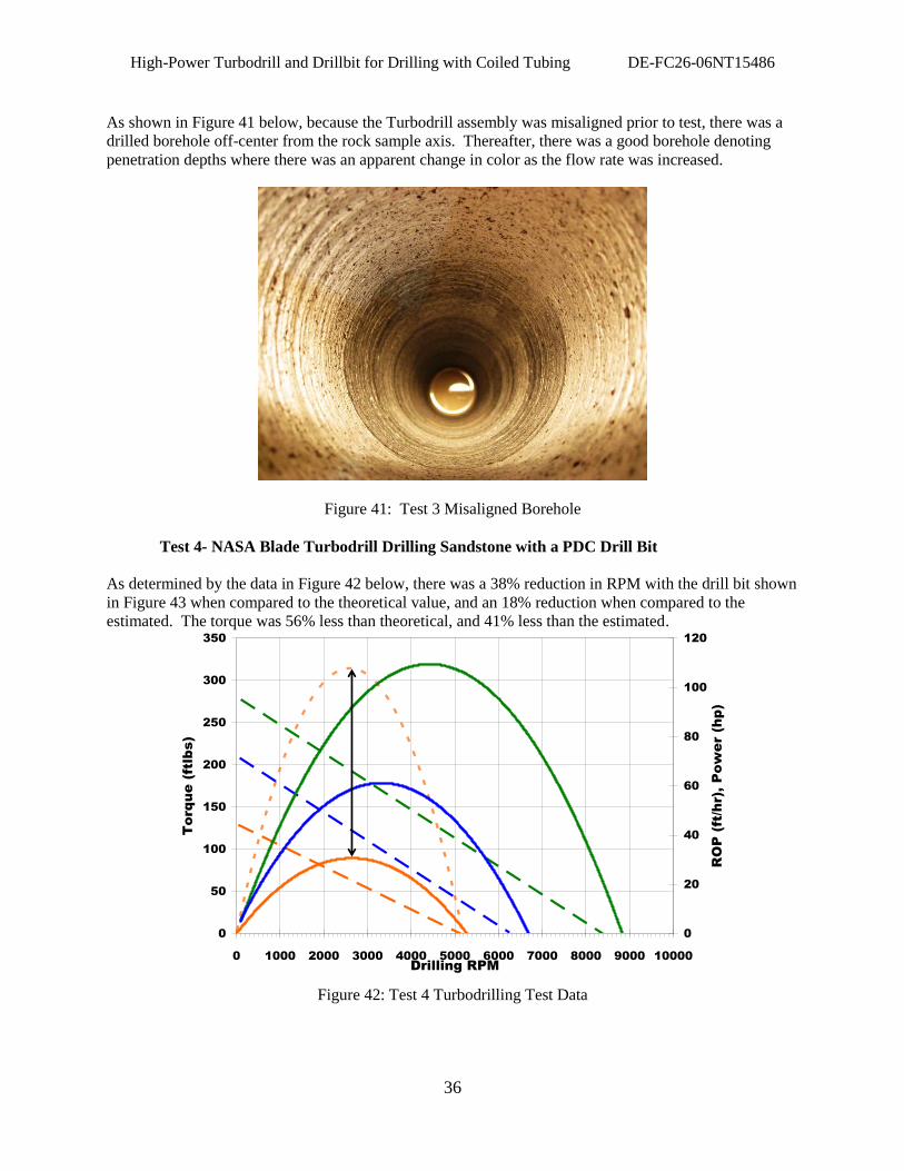
High-Power Turbodrill and Drillbit for Drilling with Coiled Tubing DE-FC26-06NT15486
36
As shown in Figure 41 below, because the Turbodrill assembly was misaligned prior to test, there was a
drilled borehole off-center from the rock sample axis. Thereafter, there was a good borehole denoting
penetration depths where there was an apparent change in color as the flow rate was increased.
Figure 41: Test 3 Misaligned Borehole
Test 4- NASA Blade Turbodrill Drilling Sandstone with a PDC Drill Bit
As determined by the data in Figure 42 below, there was a 38% reduction in RPM with the drill bit shown
in Figure 43 when compared to the theoretical value, and an 18% reduction when compared to the
estimated. The torque was 56% less than theoretical, and 41% less than the estimated. NASA + PDC Turbodrilling Sandstone
0
50
100
150
200
250
300
350
0 1000 2000 3000 4000 5000 6000 7000 8000 9000 10000
Drilling RPM
To
rq
ue
(ftlb
s)
0
20
40
60
80
100
120
RO
P (ft/h
r), P
ow
er (h
p)
Figure 42: Test 4 Turbodrilling Test Data
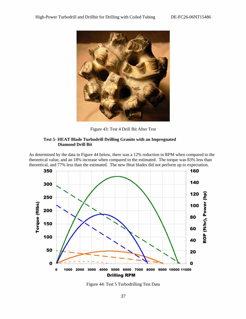
High-Power Turbodrill and Drillbit for Drilling with Coiled Tubing DE-FC26-06NT15486
37
Figure 43: Test 4 Drill Bit After Test
Test 5- HEAT Blade Turbodrill Drilling Granite with an Impregnated
Diamond Drill Bit
As determined by the data in Figure 44 below, there was a 12% reduction in RPM when compared to the
theoretical value, and an 18% increase when compared to the estimated. The torque was 83% less than
theoretical, and 77% less than the estimated. The new Heat blades did not perform up to expectation. HEAT + IMPREG Turbodrilling Granite
0
50
100
150
200
250
300
350
0 1000 2000 3000 4000 5000 6000 7000 8000 9000 10000 11000
Drilling RPM
To
rq
ue
(ftlb
s)
0
20
40
60
80
100
120
140
160
RO
P (ft/h
r), P
ow
er (h
p)
Figure 44: Test 5 Turbodrilling Test Data
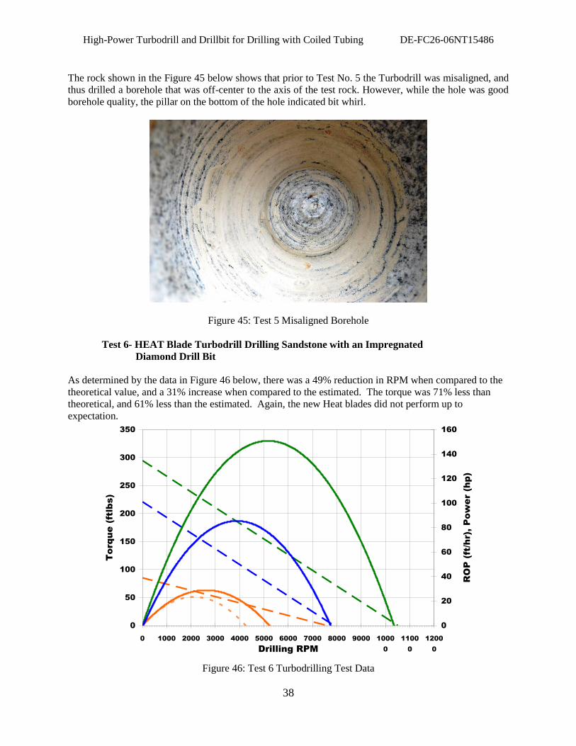
High-Power Turbodrill and Drillbit for Drilling with Coiled Tubing DE-FC26-06NT15486
38
The rock shown in the Figure 45 below shows that prior to Test No. 5 the Turbodrill was misaligned, and
thus drilled a borehole that was off-center to the axis of the test rock. However, while the hole was good
borehole quality, the pillar on the bottom of the hole indicated bit whirl.
Figure 45: Test 5 Misaligned Borehole
Test 6- HEAT Blade Turbodrill Drilling Sandstone with an Impregnated
Diamond Drill Bit
As determined by the data in Figure 46 below, there was a 49% reduction in RPM when compared to the
theoretical value, and a 31% increase when compared to the estimated. The torque was 71% less than
theoretical, and 61% less than the estimated. Again, the new Heat blades did not perform up to
expectation. HEAT + IMPREG Turbodrilling Granite
0
50
100
150
200
250
300
350
0 1000 2000 3000 4000 5000 6000 7000 8000 9000 1000
0
1100
0
1200
0Drilling RPM
To
rq
ue
(ftlb
s)
0
20
40
60
80
100
120
140
160
RO
P (ft/h
r), P
ow
er (h
p)
Figure 46: Test 6 Turbodrilling Test Data
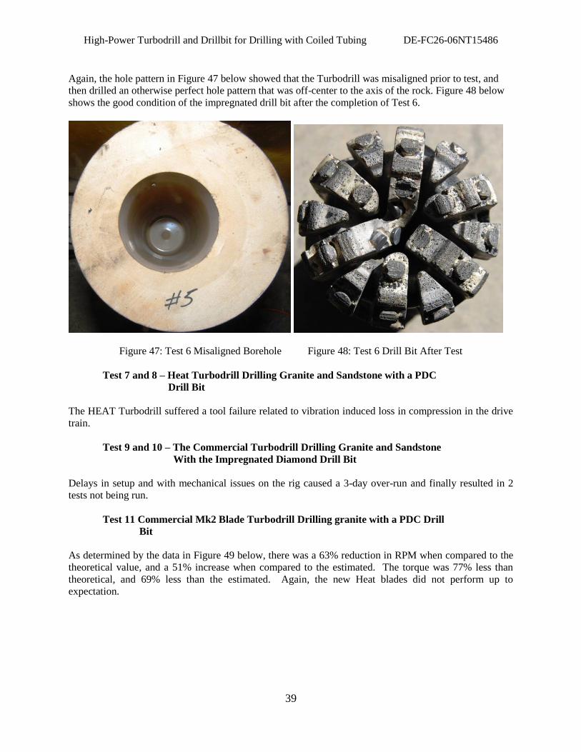
High-Power Turbodrill and Drillbit for Drilling with Coiled Tubing DE-FC26-06NT15486
39
Again, the hole pattern in Figure 47 below showed that the Turbodrill was misaligned prior to test, and
then drilled an otherwise perfect hole pattern that was off-center to the axis of the rock. Figure 48 below
shows the good condition of the impregnated drill bit after the completion of Test 6.
Figure 47: Test 6 Misaligned Borehole Figure 48: Test 6 Drill Bit After Test
Test 7 and 8 – Heat Turbodrill Drilling Granite and Sandstone with a PDC
Drill Bit
The HEAT Turbodrill suffered a tool failure related to vibration induced loss in compression in the drive
train.
Test 9 and 10 – The Commercial Turbodrill Drilling Granite and Sandstone
With the Impregnated Diamond Drill Bit
Delays in setup and with mechanical issues on the rig caused a 3-day over-run and finally resulted in 2
tests not being run.
Test 11 Commercial Mk2 Blade Turbodrill Drilling granite with a PDC Drill
Bit
As determined by the data in Figure 49 below, there was a 63% reduction in RPM when compared to the
theoretical value, and a 51% increase when compared to the estimated. The torque was 77% less than
theoretical, and 69% less than the estimated. Again, the new Heat blades did not perform up to
expectation.
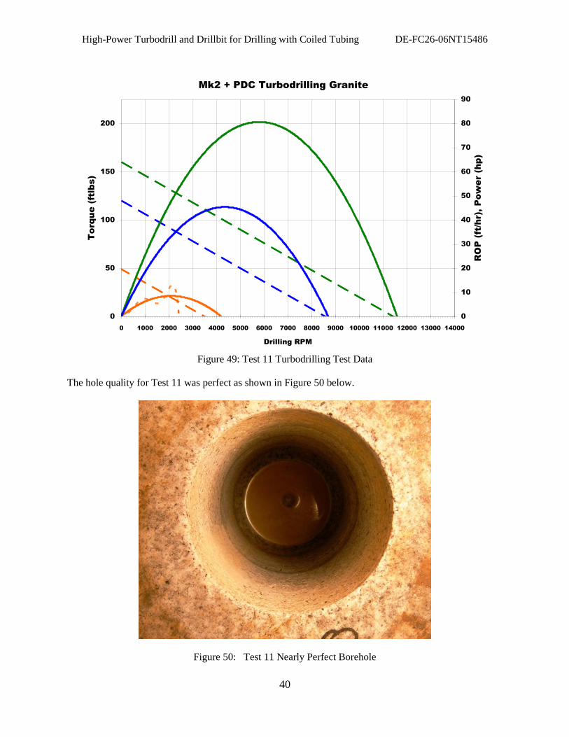
High-Power Turbodrill and Drillbit for Drilling with Coiled Tubing DE-FC26-06NT15486
40
Mk2 + PDC Turbodrilling Granite
0
50
100
150
200
0 1000 2000 3000 4000 5000 6000 7000 8000 9000 10000 11000 12000 13000 14000
Drilling RPM
Torque (ftlbs)
0
10
20
30
40
50
60
70
80
90
RO
P (ft/hr), P
ow
er (hp)
Figure 49: Test 11 Turbodrilling Test Data
The hole quality for Test 11 was perfect as shown in Figure 50 below.
Figure 50: Test 11 Nearly Perfect Borehole
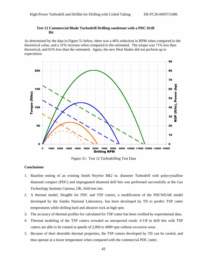
High-Power Turbodrill and Drillbit for Drilling with Coiled Tubing DE-FC26-06NT15486
41
Test 12 Commercial Blade Turbodrill Drilling sandstone with a PDC Drill
Bit
As determined by the data in Figure 51 below, there was a 46% reduction in RPM when compared to the
theoretical value, and a 31% increase when compared to the estimated. The torque was 71% less than
theoretical, and 61% less than the estimated. Again, the new Heat blades did not perform up to
expectation.
Mk2 + PDC Turbodrilling Granite
0
50
100
150
200
0 1000 2000 3000 4000 5000 6000 7000 8000 9000 10000 11000 12000 13000 14000
Drilling RPM
Torque (ftlbs)
0
10
20
30
40
50
60
70
80
90
RO
P (ft/hr), P
ow
er (hp)
Figure 51: Test 12 Turbodrilling Test Data
Conclusions
1. Baseline testing of an existing Smith Neyrfor Mk2 in. diameter Turbodrill with polycrystalline
diamond compact (PDC) and impregnated diamond drill bits was performed successfully at the Gas
Technology Institute Catoosa, OK, field test site.
2. A thermal model, DragBit for PDC and TSP cutters, a modification of the PDCWEAR model
developed by the Sandia National Laboratory, has been developed by TII to predict TSP cutter
temperatures while drilling hard and abrasive rock at high rpm.
3. The accuracy of thermal profiles for calculated for TSP cutter has been verified by experimental data.
4. Thermal modeling of the TSP cutters revealed an unexpected result: 4-1/8 in drill bits with TSP
cutters are able to be rotated at speeds of 2,000 to 4000 rpm without excessive wear.
5. Because of their desirable thermal properties, the TSP cutters developed by TII can be cooled, and
thus operate at a lower temperature when compared with the commercial PDC cutter.
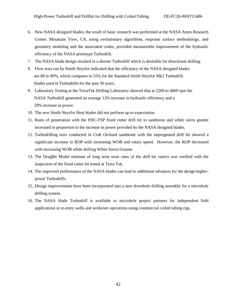
High-Power Turbodrill and Drillbit for Drilling with Coiled Tubing DE-FC26-06NT15486
42
6. New NASA designed blades, the result of basic research was performed at the NASA Ames Research
Center, Mountain View, CA, using evolutionary algorithms, response surface methodology, and
geometry modeling and the associated codes, provided measureable improvement of the hydraulic
efficiency of the NASA prototype Turbodrill.
7. The NASA blade design resulted in a shorter Turbodrill which is desirable for directional drilling.
8. Flow tests run by Smith Neyrfor indicated that the efficiency of the NASA designed blades
are 80 to 90%, which compares to 55% for the Standard Smith Neyrfor Mk2 Turbodrill.
blades used in Turbodrills for the past 30 years.
9. Laboratory Testing at the TerraTek Drilling Laboratory showed that at 2200 to 4000 rpm the
NASA Turbodrill generated an average 13% increase in hydraulic efficiency and a
29% increase in power.
10. The new Smith Neyrfor Heat blades did not perform up to expectation.
11. Rates of penetration with the PDC-TSP fixed cutter drill bit in sandstone and white sierra granite
increased in proportion to the increase in power provided by the NASA designed blades.
12. Turbodrilling tests conducted in Crab Orchard sandstone with the impregnated drill bit showed a
significant increase in ROP with increasing WOB and rotary speed. However, the ROP decreased
with increasing WOB while drilling White Sierra Granite.
13. The DragBit Model estimate of long term wear rates of the drill bit cutters was verified with the
inspection of the fixed cutter bit tested at Terra Tek.
14. The improved performance of the NASA blades can lead to additional advances for the design higher-
power Turbodrills.
15. Design improvements have been incorporated into a new downhole drilling assembly for a microhole
drilling system.
16. The NASA blade Turbodrill is available to microhole project partners for independent field
applications in re-entry wells and workover operations using commercial coiled tubing rigs.
High-Power Turbodrill and Drillbit for Drilling with Coiled Tubing DE-FC26-06NT15486
43
References
1. Seale, R. Smith Neyrfor, T. Beaton-Sii-Neyrfor, D. Conroy-Smith Bits, C. Hoffmaster-GeoDiamond,
“Turbodrill and High Speed Bit Analysis in Extreme Drilling Applications,”,2004 DEA Workshop “Step
Changes in Drilling Technology 2004,” Moody Gardens, Galveston, Texas, June 22-23, 2004.
2. Seale, R, Smith Neyrfor, T. Beaton-Smith Neyrfor, D. Conroy-Smith Bits, C. Hoffmaster-
GeoDiamond, “Turbodrill and High Speed Bit Analysis in Extreme Drilling Applications,”
DEA Workshop, June 22-23, 2004.
3. Seale, R. Smith Neyrfor, T. Beaton-Smith Neyrfor, D. Conroy-Smith Bits, C. Hoffmaster-
Geodiamond, “Technology Tackles Drilling Challenges,” The Reporter, pp. 106 to 111, July 2005
4 Terra Tek, A Schlumberger Company, “Smaller Footprint Drilling System for Deep and Hard Rock
environments; Feasibility of Ultra-High –Speed Diamond Drilling,” DOE Award No.: DE-FE26-
03NT15401, dated August 5, 2009.
5 Glowka, David, Technology International, Inc., “DragBit Users‟ Guide, PDC and TSP Fixed Cutter
Drill Bit Design Software Drill Bit Performance, Cutter Temperature, and Wear,” August 22, 2007.

High-Power Turbodrill and Drillbit for Drilling with Coiled Tubing DE-FC26-06NT15486
44
Acknowledgements
Technology International, Inc. wants to recognize the contributions of the Principal Investigator, Robert
P. Radtke, and project participants David A. Glowka, Sheila Unterreiner, and Virlen Wagner, Technology
International, Inc.; Dr. Man Mohan Rai, NASA Ames Research Laboratory; David Conroy, Dan Sarik,
Rocky Seale, Joseph Hanna, Smith Neyrfor, Dr. Anthony Griffo, Smith Bits; and Homer Robertson, Terra
Tek Drilling Laboratory. The investigation was performed with funding from the United States
Department of Energy National Energy Technology Laboratory (DOE NETL), plus cost sharing from
Smith Neyrfor and Technology International, Inc. We especially want to recognize Virginia Weyland and
Roy Long, DOE NETL, for their guidance and support.

High-Power Turbodrill and Drillbit for Drilling with Coiled Tubing DE-FC26-06NT15486
45
List of Acronyms
% percent
C Centigrade
Co Cobalt
D Depth
CM Centimeter
DOC Depth of Cut
DOE U.S. Department of Energy
E Exponent
F Fahrenheit and Force
FE Finite Element Model
FFT Fast Fourier Transfer
Ft Feet
GPM Gallons per minute
GTI Gas Technology Institute
GUI Graphical User Interface
H Height
HR Hour
Lb Pound
HS High Speed Drill Bit
Hz Hertz
ID Inside Diameter
In Inch
K Kilo
L Length
M Meter
MCTR Microhole Coiled Tubing Rig
MTBF Mean Time Between Failure
Mk2 Mark 2 Turbodrill
MT Microhole Technology
PDC Polycrystalline Diamond Cutter
Q Heat Flux
ROP Rate of Penetration

High-Power Turbodrill and Drillbit for Drilling with Coiled Tubing DE-FC26-06NT15486
46
RPM Revolutions per Minute
SCFM Standard Cubic Feet per Minute
T Temperature or Torque
TII Technology International, Inc.
TSP Thermally Stable Diamond
V Velocity
VSP Vertical Seismic Profiling
W Watts
WC Tungsten Carbide
WOB Weight on Bit
NETL AAD DOCUMENT CONTROL
BLDG. 921
U. S. DEPARTMENT OF ENERGY
NATIONAL ENERGY TECHNOLOGY LABORATORY
P. O. BOX 10940
PITTSBURGH, PA 15236-0940
National Energy Technology Laboratory
626 Cochrans Mill Road
P.O. Box 10940
Pittsburgh, PA 15236-0940
3610 Collins Ferry Road
P.O. Box 880
Morgantown, WV 26507-0880
1450 Queen Avenue SW
Albany, OR 97321-2198
2175 University Ave. South
Suite 201
Fairbanks, AK 99709 Visit the NETL website at:
www.netl.doe.gov
Customer Service:
1-800-553-7681
47