Embed Size (px)
Citation preview

01250/15 NA
Balancing valve,variable orifice
142 series
Product range
142 series Variable orifice balancing valve sizes 1/2”, 3/4”, 1”, 1 1/4”, 1 1/2”, and 2" NPT female
CALEFFI
DimensionsTechnical specifications
MaterialsValve Body: DZR low-lead brassBonnet: DZR low-lead brassValve adjustment plug: DZR low-lead brassHydraulic seals: EPDMAdjustment knob: PA6G30Pressure test ports: DZR low-lead brass body, EPDM seal elements
Reduction of Lead in Drinking Water Act Compliant: 0.25% Max. weighted average lead content. Reduction of Lead in Drinking Water Act Certified by IAPMO R&T. PerformanceSuitable Fluids: water, glycol solutionsMax. percentage of glycol: 50%Max. working pressure: 232 psi (16 bar)Working temperature range: 15 - 250°F (-10–120°C)Accuracy: ±15%Number of adjustment turns: 4Threaded connections: 1/2”– 2" FNPT
InsulationMaterials: EPPThickness: ½ inch (15mm)Density: 2.8 lb/ft³ (45 kg/m³)Thermal conductivity (ISO 2581): - at 50°F (10°C): BTU · in/hr · ft² · °F (0.037 W/m · K))Working temperature range: 23 - 250°F (-5 - 120°C)Reaction to fire (UL 94): Class HBF
ISO 9001 No. 0003
ACCREDITED
ISO 9001 FM 21654
Function
Caleffi 142 series low lead manual balancing valves are used to measure and adjust the fluid flow rate in hydronic or plumbing circuits. Turning the knob moves a plug within the fluid stream which varies the flow rate. The flow rate is determined from the pressure drop created across the two test ports as the fluid passes the adjustment plug. The pressure drop value is measured by a differential pressure meter connected to the pressure test ports. The valve design is variable orifice with pressure ports located upstream and downstream of the adjustment plug. A memory stop feature allows the valve to be closed, and later reopened to the original set position. Optional insulation shells are available, purchase separately.
A1/2"
3/4"
1"
DN15
20
25
Code140.40
140.50
B
140.60
65
75
85
C106,5
106,5
112,5
0,790
0,924
1,185
B
C
A
D
D Mass (kg)
69
69
69
B
C
A
DN15
20
25
A1/2"
3/4"
1"
Code142140
142150
142160
B65
75
85
C64
64
64
0,434
0,523
0,677
Mass (kg)Code A B C Wt (lb)
142241A ½" 2 9/16" 2 ½" 1.0142251A ¾" 2 15/16" 2 ½" 1.2142261A 1" 3 7/16" 2 ½" 1.5142271A 1 ¼" 3 ¾" 3 ¼" 2.3142281A 1 ½" 3 15/16" 3 3/8" 3.0142291A 2" 4 ¾" 3 3/8" 3.5

Advantages of balanced circuits
Balanced circuits have the following principal benefi ts:
1. In hydronic applications, the system emitters operate properly saving energy and providing greater comfort.2. In plumbing applications such as hot water recirculation, water is not wasted when there is a call for hot water from a fi xture.3. Circuit pumps operate at maximum effi ciency, reducing the risk of overheating and excessive wear.4. High fl uid velocities which can result in noise, erosion and abrasion are avoided.5. The differential pressures acting on the circuit control valves are reduced preventing faulty operation.
Operating principle
The 142 series balancing valve is a hydraulic device that controls the fl ow rate of a fl uid. Turning the knob moves a plug within the fl uid stream which varies the fl ow rate. The fl ow rate is determined according to the pressure drop value measured by a differential pressure meter connected to the pressure test ports and the adjustment knob position.
Construction details
Adjustment knob
The knob is made of a reinforced high strength corrosion-resistant polymer. The shape of the knob is designed to ensure maximum comfort for the operator and an accurate adjustment.
Adjustment reference scale
Each 360° rotation of the knob moves the turn indicator by one position, ranging from 0 (valve closed) to 4 (valve fully open).
OPEN
CLOSE
RESET ON OF FBT OFF
Measuringprobe
Safetycap
Seal
OPEN
CLOSE
RESET ON OF FBT OFF
Memory stop
After adjusting the fl ow rate, insert a 2.5 mm hex key in the hex hole, fully turn it clockwise without forcing it. This sets the valve's maximum stroke position. If necessary, it is possible to shutoff the balancing valve by turning the adjustment knob fully clockwise manually. To restore the valve to the pre-set position, turn the adjustment knob fully counter-clockwise.
Fast-coupling pressure test ports
The 142 series balancing valve has as standard probe type, fast-coupling pressure test ports. The probe from the differential pressure meter is inserted into the port packing, until the end of the probe enters the system. When the measuring probe is pulled out, the test port automatically closes, preventing fl uid leakage. Care should be taken to pull the probe out slowly so as to allow adequate time for the packing to re-seal – otherwise fl uid can quickly escape creating a hazardous situation. Consult differential pressure meter manufacturer instructions for proper use of instrument and pressure port couplings.

Insulation shells
The 142 series balancing valve can be supplied with optional insulation shells, code CBN142xxxx series purchased separately, to minimize heat loss or elim-inate condensation in chilled water applications.
Code Size
CBN142241A Fits ½"
CBN142251A Fits ¾"
CBN142261A Fits 1"
CBN142271A Fits 1¼"
CBN142281A Fits 1½"
USING AND SETTING THE BALANCING VALVE
Measuring the flow rate
The 142 series balancing valves contain pressure test ports located upstream and downstream of the valve plug. As fluid flows through the valve and past the adjustment plug, a differential pressure across the two ports is induced. By measuring this differential pressure value and knowing the flow coefficient of the valve (corresponding to the knob position) the flow rate can be determined.
When fluid medium is water
When the fluid is water, the flow rate can be determined by either referencing the flow characteristics chart for the respective valve size, or by using the formula G = Cv ∙ √∆P where G is the flow rate in gpm, Cv is the flow coefficient of the balancing valve, and ∆P is the pressure differential in psi.
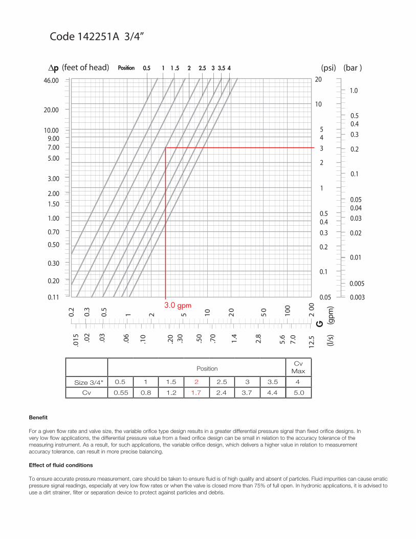
Example (see graph on next page), for balancing valve code 142251A (¾") with the knob position set to position #2, and the differential pressure measured to be 3.0 psi, find the point on the chart where the 3.0 psi value intersects the position #2 line. Drop a line vertically to intersect the gpm axis and estimate the corresponding flow rate to be 3 gpm. Alternately, we can determine the flow rate G by substituting the values into the above formula: G = 1.7√3 = 3 gpm, where 1.7 is the value Cv at position #2.
When fluid medium is other than water
A correction factor for calculating flowrate needs to be applied when using fluids with viscosities similar to water (which is the case for most glycol and salt based anti-freeze solutions). GA = , where GA is the actual flow rate of the fluid, G is the calculated value from the chart or formula, and SGF is the specific gravity of the fluid.
For example, if a 50% polypropylene glycol solution is the medium instead of water, we must first determine the specific gravity, which is 1.04. The actual flow rate can be the calculated as: GA = = = 3/1.02 = 2.94 gpm.
GSG� F
GSG� F
3.01.04�
.03
.06
Δp
G(l/
s)
(gpm
)
0.1
1
0.2
0.3
0.5
(psi) (bar )
10
2
3
5
20
0.01
0.1
0.02
0.03
0.05
1.0
0.2
0.3
0.5
0.4
4
0.04
0.4
.30
.50
1.4
2.8
5.6
10.2
0.5
2 5 10 20
50
100
200
.015
46.00
20.00
10.009.007.00
5.00
2.00
1.50
1.00
0.70
0.50
0.20
(feet of head)
0.05
3.00
0.30
0.11 0.003
0.0057.
0
12.5.0
20.
3
.10
.20
.70
3.0 gpm
2 3Position 1 2.5 0.5 1 .5 3.5 4
Cv Max
Size 3/4" 0.5 1 1.5 2 2.5 3 3.5
Cv 0.55 0.8 1.2 1.7 2.4 3.7 4.4 5.0
Position
4
Code 142251A 3/4”
Benefit
For a given flow rate and valve size, the variable orifice type design results in a greater differential pressure signal than fixed orifice designs. In very low flow applications, the differential pressure value from a fixed orifice design can be small in relation to the accuracy tolerance of the measuring instrument. As a result, for such applications, the variable orifice design, which delivers a higher value in relation to measurement accuracy tolerance, can result in more precise balancing.
Effect of fluid conditions
To ensure accurate pressure measurement, care should be taken to ensure fluid is of high quality and absent of particles. Fluid impurities can cause erratic pressure signal readings, especially at very low flow rates or when the valve is closed more than 75% of full open. In hydronic applications, it is advised to use a dirt strainer, filter or separation device to protect against particles and debris.

USING AND SETTING THE BALANCING VALVE
Presetting
The 142 series balancing valve features highly graduated adjustment which facilitates pre-setting. In commercial balancing applications where multiple balancing valves are used, significant labor time can be saved in the balancing process if in advance of being installed, the valves are pre-set to the expected knob position value. To pre-set, the anticipated pressure drop across the valve is required. For example, if it has been calculated that to accomplish a flow rate of 3.0 gpm in a circuit, a 3.0 psi pressure drop across the balancing valve will be required, the knob should be preset to position #2.
.03
.06
∆p
G(l/
s)
(gpm
)
0.1
1
0.2
0.3
0.5
(psi) (bar)
10
2
3
5
20
0.01
0.1
0.02
0.03
0.05
1.0
0.2
0.3
0.5
0.4
4
0.04
0.4
.30
.50
1.4
2.8
5.6
10.2
0.5
2 5 10
20
50
10
0
20
0
.015
46.00
20.00
10.009.007.005.00
2.001.50
1.00
0.70
0.50
0.20
(feet of head)
0.05
3.00
0.30
0.10 0.003
0.005
7.0
12.5.02
0.3
.10
.20
.70
0.02
0.006
0.01
0.03
0.005
0.008
0.05
0.030.02
0.0150.0115
0.0006
0.001
0.00040.00035
0.002
2 3Position
1 2.5 0.5 1 .5 3.5
4
Cv Max
Size 1/2" 0.5 1 1.5 2 2.5 3 3.5
Cv 0.37 0.63 1.07 1.6 2.13 2.9 3.3 3.4
Position
4
Code 142241A 1/2”
.03
.06
∆p
G(l/
s)
(gpm
)
0.1
1
0.2
0.3
0.5
(psi) (bar )
10
2
3
5
20
0.01
0.1
0.02
0.03
0.05
1.0
0.2
0.3
0.5
0.4
4
0.04
0.4
.30
.50
1.4
2.8
5.6
10.2
0.5
2 5 10 20
50
100
200
.015
46.00
20.00
10.009.007.00
5.00
2.00
1.50
1.00
0.70
0.50
0.20
(feet of head)
0.05
3.00
0.30
0.10 0.003
0.005
7.0
12.5.0
20.
3
.10
.20
.70
0.02
0.006
0.01
0.03
0.005
0.008
0.05
0.030.02
0.015
0.0115
0.0006
0.001
0.00040.00035
0.002
2 3Position 1 2.5 0.5 1 .5 3.5 4
Cv Max
Size 3/4" 0.5 1 1.5 2 2.5 3 3.5
Cv 0.55 0.8 1.2 1.7 2.4 3.7 4.4 5.0
Position
4
Code 142251A 3/4”
3.0 gpm
.03
.06
∆p
G(l/
s)
(gpm
)
0.1
1
0.2
0.3
0.5
(psi) (bar)
10
2
3
5
20
0.01
0.1
0.02
0.03
0.05
1.0
0.2
0.3
0.5
0.4
4
0.04
0.4
.30
.50
1.4
2.8
5.6
10.2
0.5
2 5 10
20
50
100
200
.015
46.00
20.00
10.009.007.005.00
2.001.50
1.00
0.70
0.50
0.20
(feet of head)
0.05
3.00
0.30
0.10 0.003
0.005
7.0
12.5.02
0.3
.10
.20
.70
0.02
0.006
0.01
0.03
0.005
0.008
0.05
0.030.02
0.0150.0115
0.0006
0.001
0.00040.00035
0.002
Code 142261A 1” 2 3Position 1 2.5 0.5 1 .5 3.5 4
Cv Max
Size 1" 0.5 1 1.5 2 2.5 3 3.5
Cv 1.0 1.2 1.8 2.6 3.3 5.0 6.5 7.5
Position
4
.03
.06
∆p
G(l/
s)
(gpm
)
0.1
1
0.2
0.3
0.5
(psi) (bar)
10
2
3
5
20
0.01
0.1
0.02
0.03
0.05
1.0
0.2
0.3
0.5
0.4
4
0.04
0.4
.30
.50
1.4
2.8
5.6
10.2
0.5
2 5 10
20
50
100
200
.015
46.00
20.00
10.009.007.005.00
2.001.50
1.00
0.70
0.50
0.20
(feet of head)
0.05
3.00
0.30
0.10 0.003
0.005
7.0
12.5.02
0.3
.10
.20
.70
0.02
0.006
0.01
0.03
0.005
0.008
0.05
0.030.02
0.0150.0115
0.0006
0.001
0.00040.00035
0.002
Code 142271A 1 1/4” 2 3Position 1 2.5 0.5 1 .5 3.5 4
Cv Max
Size 1 1/4" 0.5 1 1.5 2 2.5 3 3.5
Cv 1.5 2.6 3.6 4.5 7.7 10.0 11.8 12.9
Position
4
Code 142241A 1/2" Code 142251A 3/4"
Code 142261A 1" Code 142271A 1 1/4"

.03
.06
∆p
G(l/
s)
(gpm
)0.1
1
0.2
0.3
0.5
(psi) (bar)
10
2
3
5
20
0.01
0.1
0.02
0.03
0.05
1.0
0.2
0.3
0.5
0.4
4
0.04
0.4.3
0
.50
1.4
2.8
5.6
10.2
0.5
2 5 10
20
50
10
0
200
.01
5
46.00
20.00
10.009.007.005.00
2.001.50
1.00
0.70
0.50
0.20
(feet of head)
0.05
3.00
0.30
0.10 0.003
0.005
7.0
12
.5.02
0.3
.10
.20
.70
0.02
0.006
0.01
0.03
0.005
0.008
0.05
0.030.02
0.0150.0115
0.0006
0.001
0.00040.00035
0.002
Code 142281A 1 1/2” 2 3Position 1 2.5 0.5 1 .5 3.5 4
Cv Max
Size 1 1/2" 0.5 1 1.5 2 2.5 3 3.5
Cv 2.0 3.3 5.6 8.1 10.9 13.4 14.9 16.8
Position
4
.03
.06
∆p
G(l/
s)
(gpm
)
0.1
1
0.2
0.3
0.5
(psi) (bar)
10
2
3
5
20
0.01
0.1
0.02
0.03
0.05
1.0
0.2
0.3
0.5
0.4
4
0.04
0.4
.30
.50
1.4
2.8
5.6
10.2
0.5
2 5 10
20
50
10
0
200
.01
5
46.00
20.00
10.009.007.005.00
2.001.50
1.00
0.70
0.50
0.20
(feet of head)
0.05
3.00
0.30
0.10 0.003
0.005
7.0
12
.5.02
0.3
.10
.20
.70
0.02
0.006
0.01
0.03
0.005
0.008
0.05
0.030.02
0.0150.0115
0.0006
0.001
0.00040.00035
0.002
Code 142291A 2” 2 3Position 1 2.5 0.5 1 .5 3.5 4
Cv Max
Size 2" 0.5 1 1.5 2 2.5 3 3.5
Cv 2.3 5.5 7.2 10.2 13.2 17.1 20.0 22.0
Position
4
Valve flow coefficient Cv versus knob position
Knob position ½"142241A
¾"142251A
1"142261A
1 ¼"142271A
1 ½"142281A
2"142291A
0.5 0.37 0.55 1.0 1.5 2.0 2.3
1.0 0.63 0.8 1.2 2.6 3.3 5.5
1.5 1.07 1.2 1.8 3.6 5.6 7.2
2.0 1.6 1.7 2.6 4.5 8.1 10.2
2.5 2.13 2.4 3.3 7.7 10.9 13.2
3.0 2.9 3.7 5.0 10.0 13.4 17.1
3.5 3.3 4.4 6.5 11.8 14.9 20.0
max 4.0 3.4 5.0 7.5 12.9 16.8 22.0
Flow formulas
∆p = (G/Cv)²G = Cv · √∆p Cv = G
∆p�
Code 142281A 1 1/2" Code 142291A 2"

To balance zone branches in circuits with three-way valves.
To balance potable water distribution circuits.
Application diagrams
To control the flow rate that flows to each riser. To control the flow rate supplying each emitter.

To balance circuts that supply the coils of air handling units. To balance circuits that supply cooling towers.
G R 1 G R 2
G R 1 G R 2
To balance circuits that supply cooling unit evaporators or condensers.
To balance the various substations in district heating systems.
s
To balance the by-pass line in circuits for temperature control.
s
To balance primary/secondary coupled circuits.
Application diagrams

142 seriesBalancing valve with variable orifice. Threaded connections 1/2”, 3/4", 1", 1-1/4", 1-1/2", 2" NPT Female by Female. DZR low-lead brass body, bonnet and valve plug (< 0.25% lead content) certified by IAPMO R&T. EPDM hydraulic seals. PA6G30 adjusting knob with memory stop. Pressure test ports with DZR low-lead brass body and EPDM seal elements. Water and glycol solutions. Maximum percentage of glycol 50%. Maximum working pressure 232 psi (16 bar). Working temperature range 15 to 250 deg F (-10 to 120°C). Number of adjustment turns: 4. Accuracy ± 15%. Pre-formed insulation shells available for field installation.
SPECIFICATION SUMMARIES
We reserve the right to change our products and their relevant technical data, contained in this publication, at any time and without prior notice.
Caleffi North America, Inc.3883 W. Milwaukee RoadMilwaukee, WI 53208Tel: 414-238-2360 · Fax: [email protected] · www.caleffi.us© Copyright 2015 Caleffi North America, Inc.