Embed Size (px)
Citation preview
Fluid System Building Blocks• Basic Modeling Elements
– Resistance
– Capacitance
– Inertance
– Pressure and Flow Sources
• Interconnection Relationships– Compatibility Law
– Continuity Law
Thermal System Building Blocks
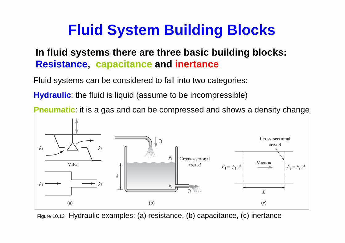
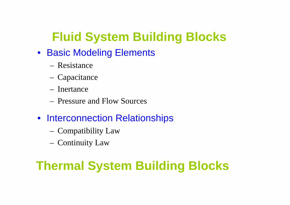
Figure 10.13 Hydraulic examples: (a) resistance, (b) capacitance, (c) inertance
Fluid System Building BlocksIn fluid systems there are three basic building blo cks: Resistance , capacitance and inertance
Fluid systems can be considered to fall into two categories:
Hydraulic : the fluid is liquid (assume to be incompressible)
Pneumatic : it is a gas and can be compressed and shows a density change
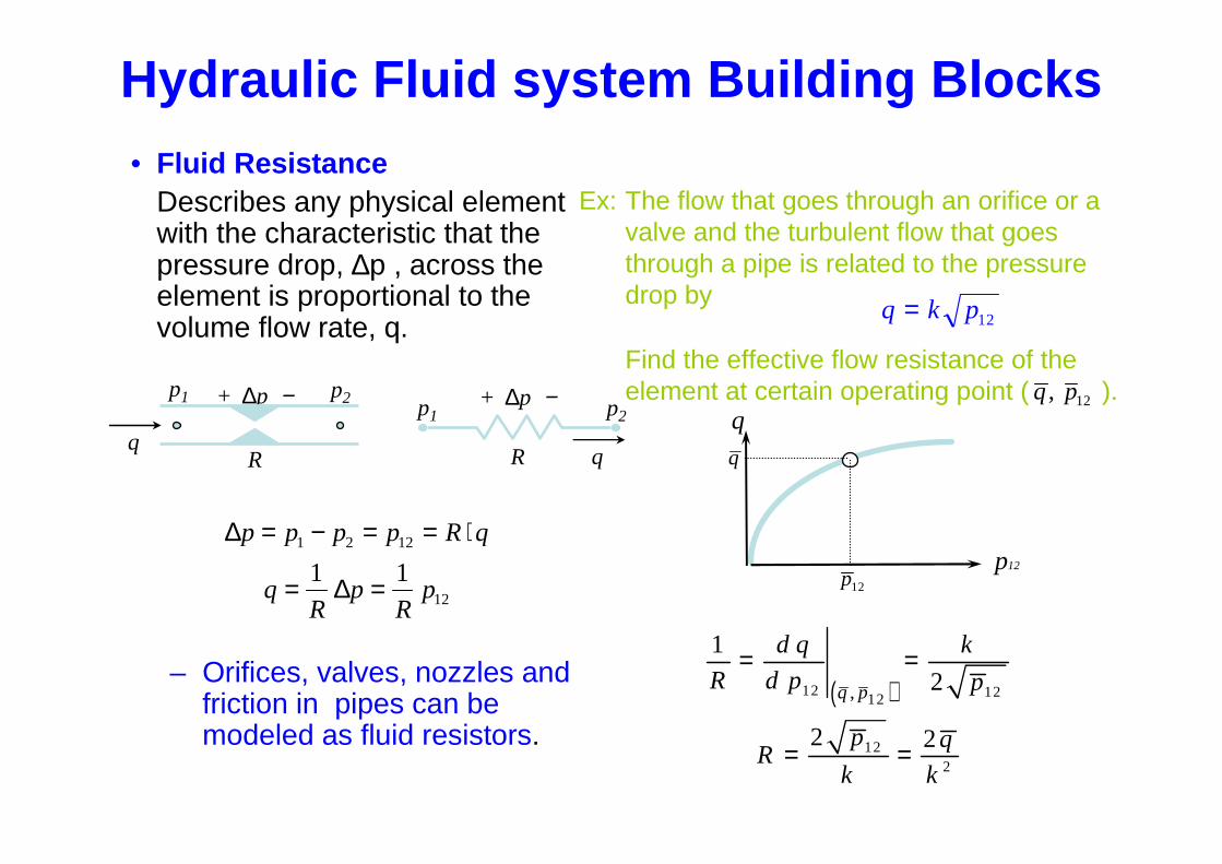
• Fluid ResistanceDescribes any physical element with the characteristic that the pressure drop, ∆p , across the element is proportional to the volume flow rate, q.
– Orifices, valves, nozzles and friction in pipes can be modeled as fluid resistors.
Hydraulic Fluid system Building Blocks
∆
∆
p p p p R q
qR
pR
p
= − = = ⋅
= =
1 2 12
12
1 1
Ex: The flow that goes through an orifice or a valve and the turbulent flow that goes through a pipe is related to the pressure drop by
Find the effective flow resistance of the element at certain operating point ( ).q p, 12
q k p= 12
q
p12
( )12 12
122
12,
1
2
2 2
q p
d q k
R d p p
p qR
k k
= =
= =
qR
+ ∆p −p1 p2+ ∆p −
R
p1 p2
p12
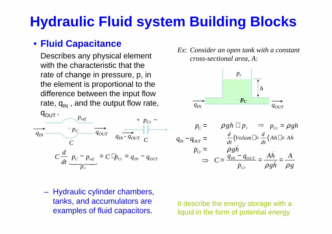
• Fluid CapacitanceDescribes any physical element with the characteristic that the rate of change in pressure, p, in the element is proportional to the difference between the input flow rate, qIN , and the output flow rate, qOUT .
– Hydraulic cylinder chambers, tanks, and accumulators are examples of fluid capacitors.
ghρ
Cd
dtp p C p q qC ref Cr IN OUT
pCr
− = ⋅ = −1 24 34
&
qIN
pref
C
pC qOUT
CqIN - qOUT
+ pCr −
Ex: Consider an open tank with a constant cross-sectional area, A:
qIN qOUT
pC
h
pr
C
IN OUT
Cr
p
q q
p
C
=
− ==⇒ =
&
( ) ( )d dVolum Ah Ah
dt dt= = &
rgh pρ + ⇒Crp ghρ=
ghρ &
IN OUT
Cr
q q Ah A
p ggh ρρ− = =
&
&&
Hydraulic Fluid system Building Blocks
It describe the energy storage with a liquid in the form of potential energy
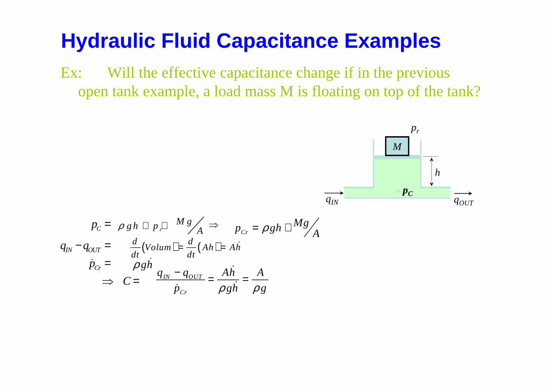
Ex: Will the effective capacitance change if in the previous open tank example, a load mass M is floating on top of the tank?
Hydraulic Fluid Capacitance Examples
qIN qOUT
pC
h
pr
M
C
IN OUT
Cr
p
q q
p
C
=
− ==⇒ =
&
( ) ( )d dVolum Ah Ah
dt dt= = &
rM gg h p Aρ + + ⇒
CrMgp gh Aρ= +
ghρ &
IN OUT
Cr
q q Ah A
p ggh ρρ− = =
&
&&
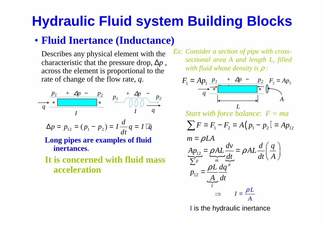
• Fluid Inertance (Inductance)Describes any physical element with the characteristic that the pressure drop, ∆p , across the element is proportional to the rate of change of the flow rate, q.
Long pipes are examples of fluid inertances.
It is concerned with fluid mass acceleration
1 1F Ap=
∆p p p p Id
dtq I q= = − = = ⋅12 1 2( ) &
Ex: Consider a section of pipe with cross-sectional area A and length L, filled with fluid whose density is ρ :
Start with force balance: F = maIq
p1 p2+ ∆p −
q
+ ∆p −
I
p1 p2
L
q
p1 p2+ ∆p −
A
⇒ = IL
A
ρ
2 2F Ap=1 1F Ap=
( )1 2 1 2 12F F F A p p Ap= − = − =∑m LAρ=
{ {{
12
mFa
dv d qAp AL AL
dt dt Aρ ρ = =
∑
{12
I
L dqp
A dt
ρ=
Hydraulic Fluid system Building Blocks
I is the hydraulic inertance
• Pneumatic has the same three basic building blocks with hydraulic systems.
• Gases differ from liquids in being compressible i.e. change in pressure causes change in volume and hence density:
• The basic blocks are:• Pneumatic Resistance, • Pneumatic capacitance, & • Pneumatic Inertance
Pneumatic Fluid system Building Blocks
Pneumatic Fluid system Building Blocks
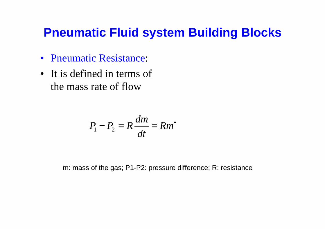
• Pneumatic Resistance:
• It is defined in terms of the mass rate of flow
•==− Rmdt
dmRPP 21
m: mass of the gas; P1-P2: pressure difference; R: resistance
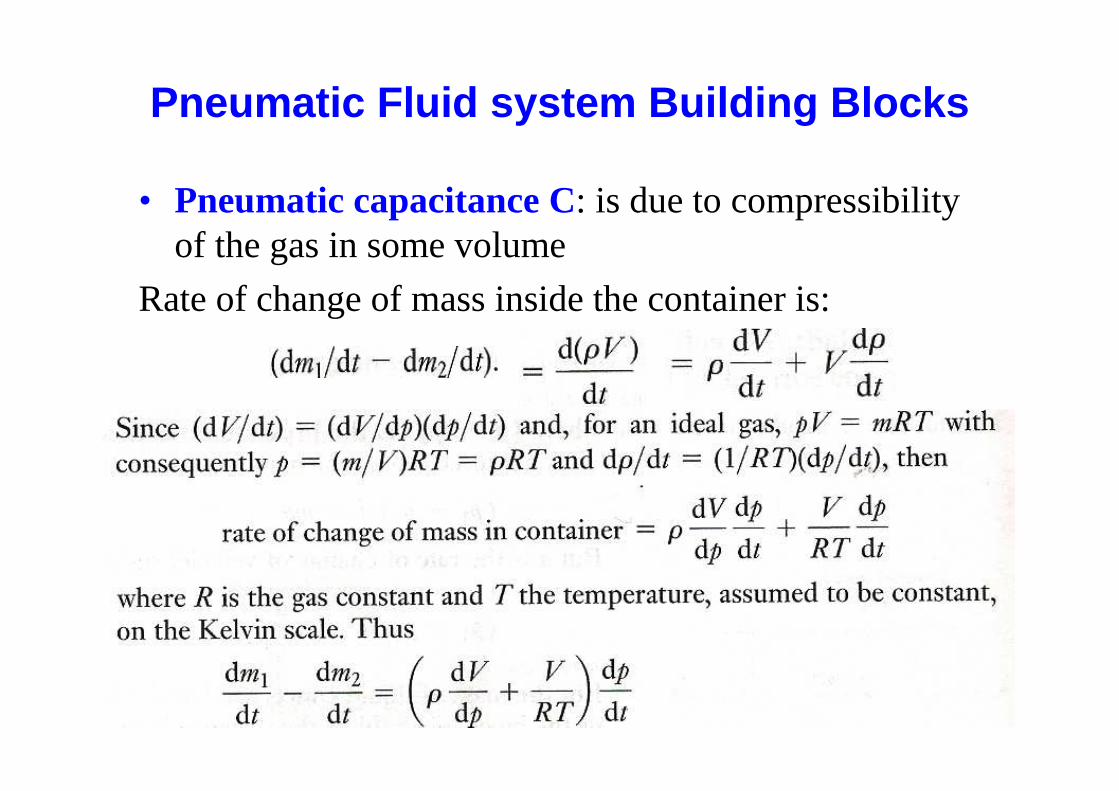
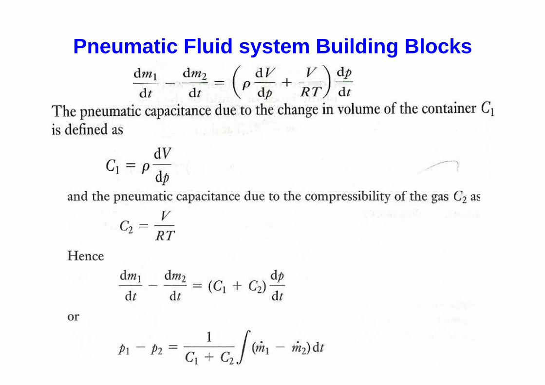
• Pneumatic capacitance C: is due to compressibility of the gas in some volume
Rate of change of mass inside the container is:
Pneumatic Fluid system Building Blocks
Pneumatic Fluid system Building Blocks
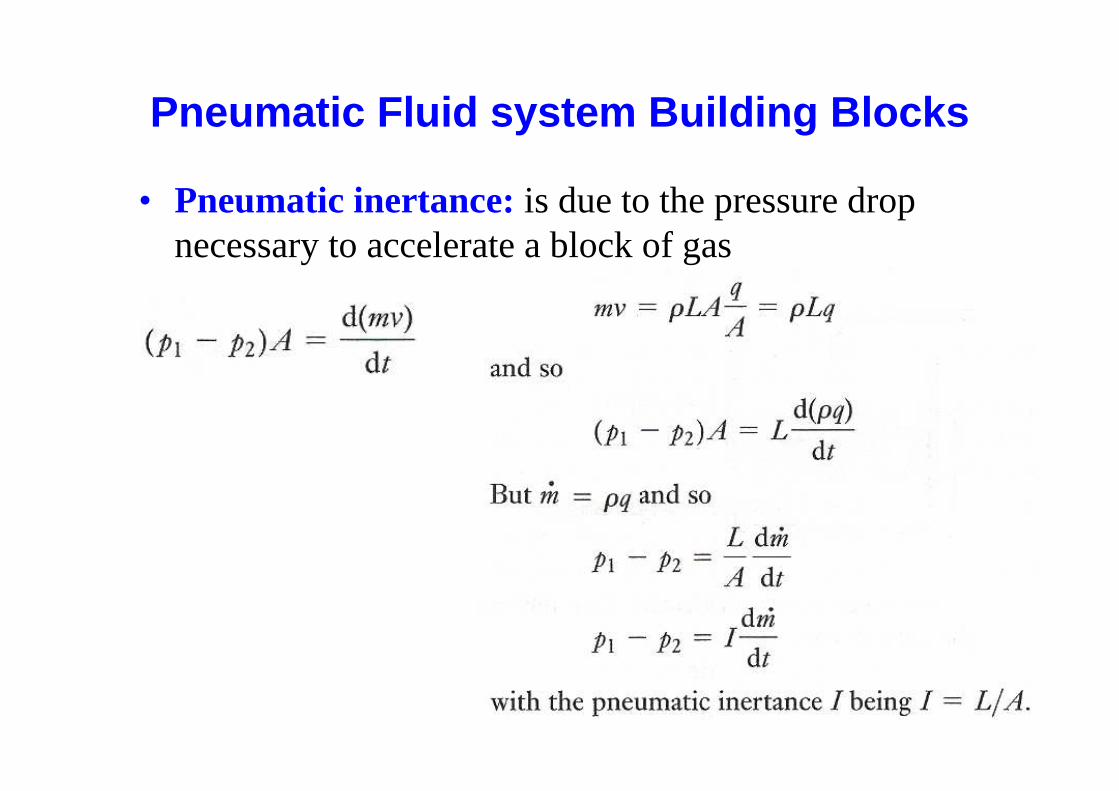
• Pneumatic inertance: is due to the pressure drop necessary to accelerate a block of gas
Pneumatic Fluid system Building Blocks
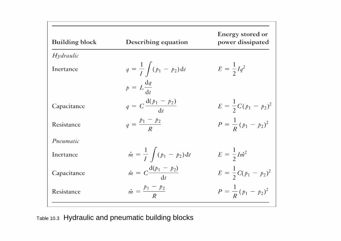
Table 10.3 Hydraulic and pneumatic building blocks
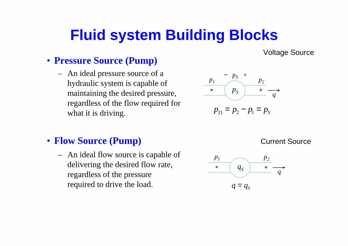
• Pressure Source (Pump)– An ideal pressure source of a
hydraulic system is capable of maintaining the desired pressure, regardless of the flow required for what it is driving.
• Flow Source (Pump)– An ideal flow source is capable of
delivering the desired flow rate, regardless of the pressure required to drive the load.
− pS +p1 p2
pS q
p p p pS21 2 1= − =
p1 p2
qS q
q qS=
Voltage Source
Current Source
Fluid system Building Blocks
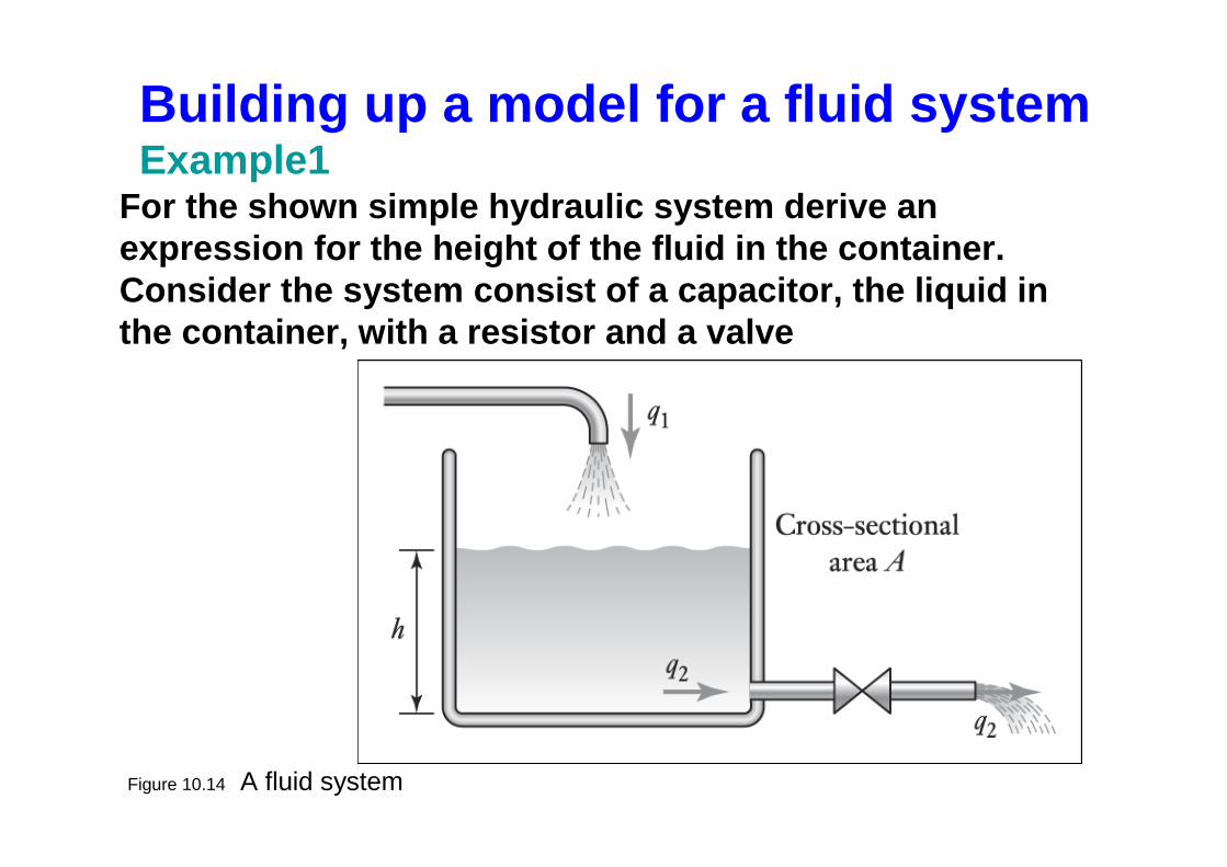
Figure 10.14 A fluid system
Building up a model for a fluid system Example1
For the shown simple hydraulic system derive an expression for the height of the fluid in the conta iner. Consider the system consist of a capacitor, the liq uid in the container, with a resistor and a valve
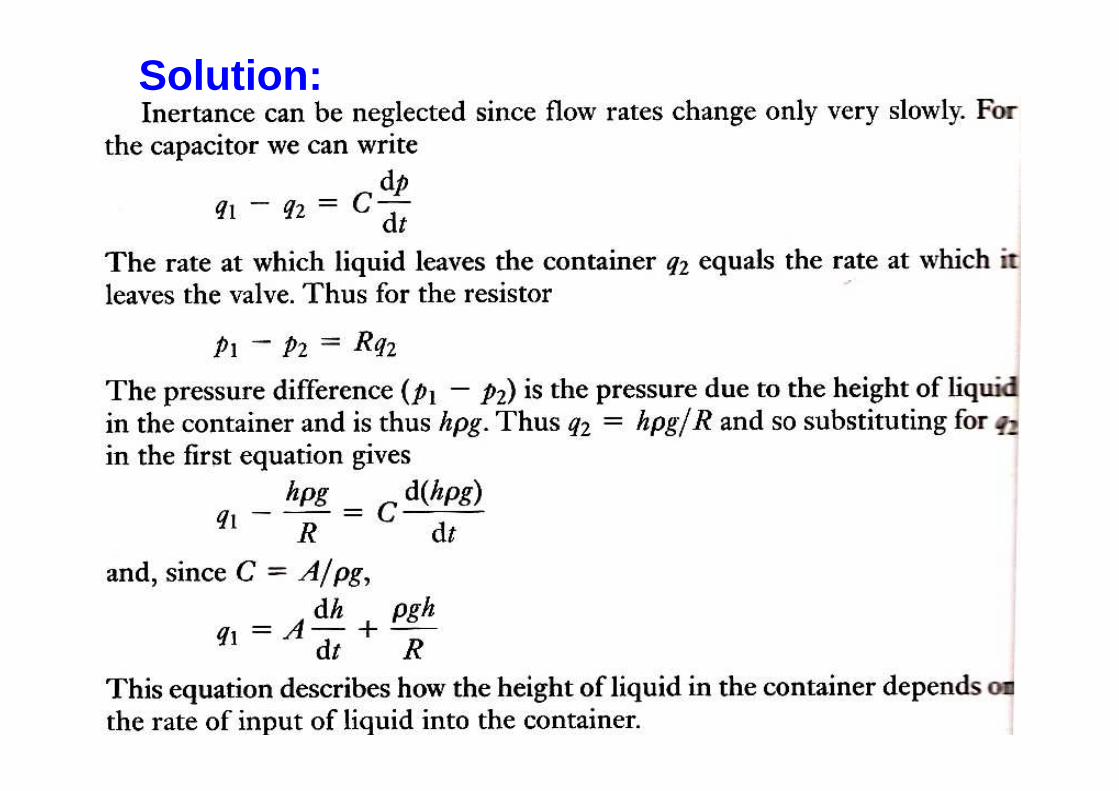
Solution:
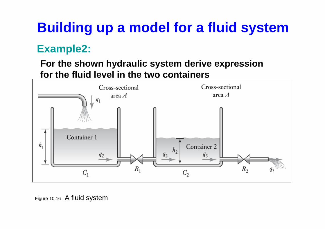
Figure 10.16 A fluid system
Building up a model for a fluid systemExample2:For the shown hydraulic system derive expression for the fluid level in the two containers
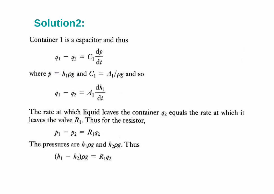
Solution2:
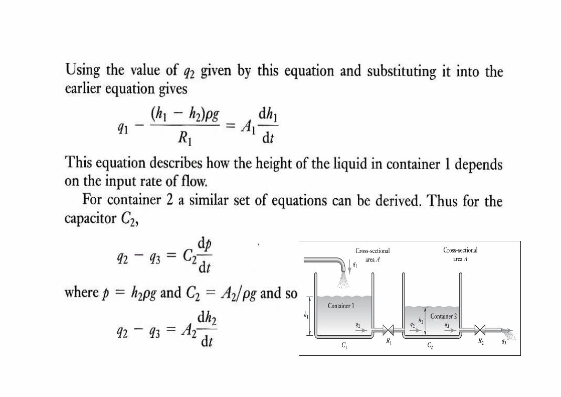
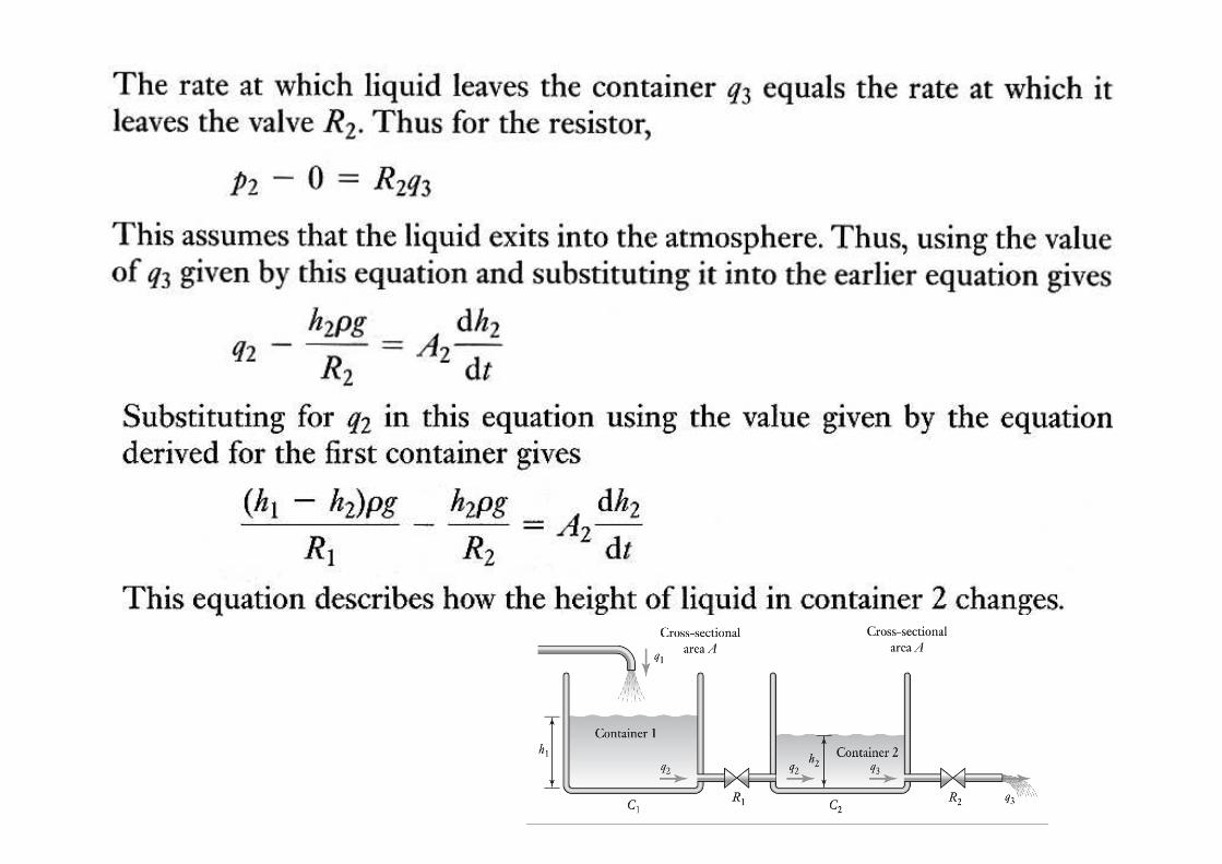
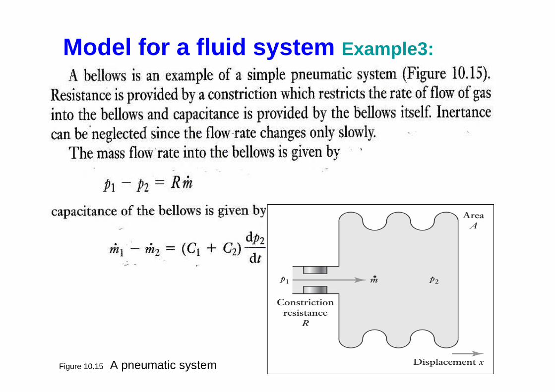
Figure 10.15 A pneumatic system
Model for a fluid system Example3:
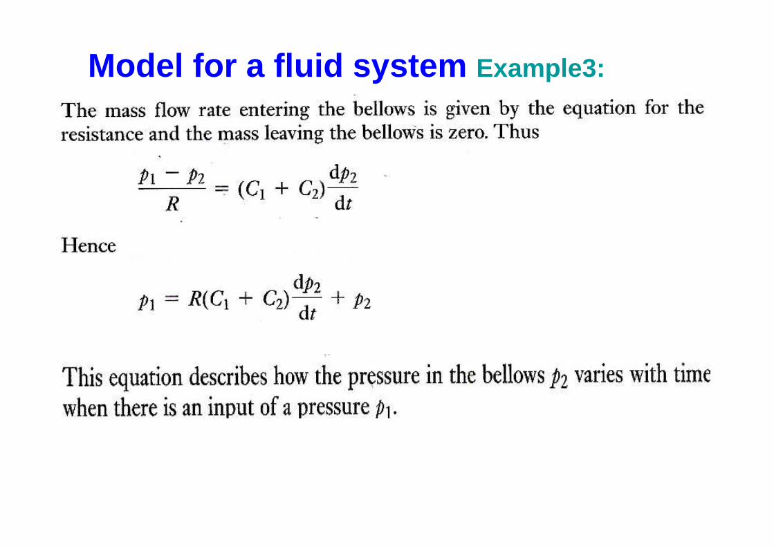
Model for a fluid system Example3:
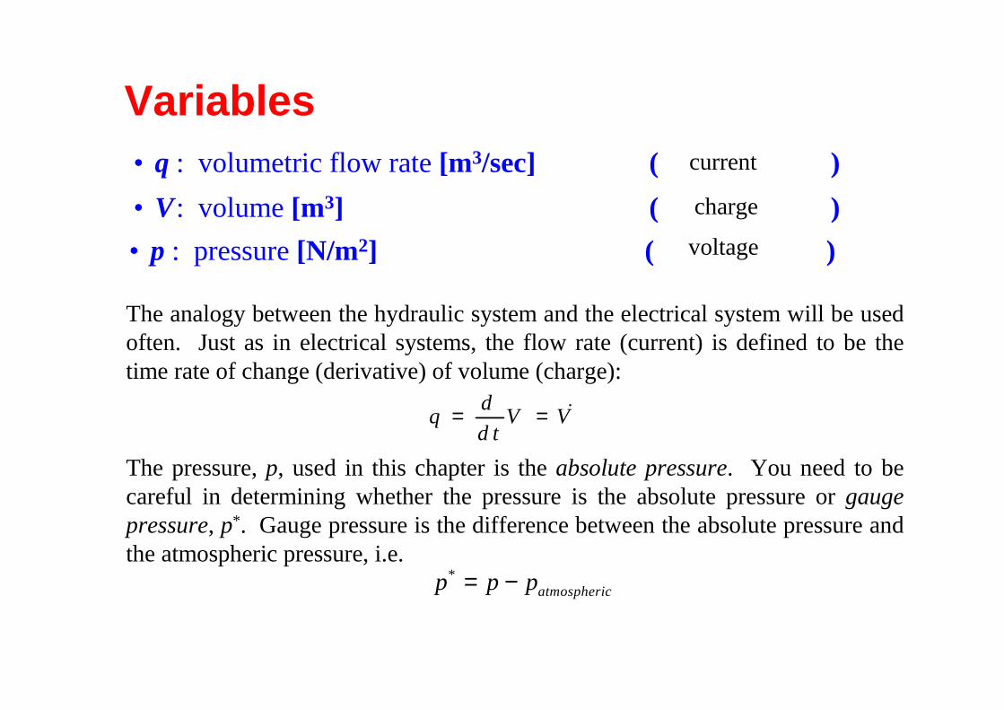
The analogy between the hydraulic system and the electrical system will be used often. Just as in electrical systems, the flow rate (current) is defined to be the time rate of change (derivative) of volume (charge):
The pressure, p, used in this chapter is the absolute pressure. You need to be careful in determining whether the pressure is the absolute pressure or gauge pressure, p*. Gauge pressure is the difference between the absolute pressure and the atmospheric pressure, i.e.
Variables• q : volumetric flow rate [m3/sec] ( )
p p patmospheric* = −
dq V V
d t= = &
current
voltage• p : pressure [N/m2] ( )
charge• V: volume [m3] ( )
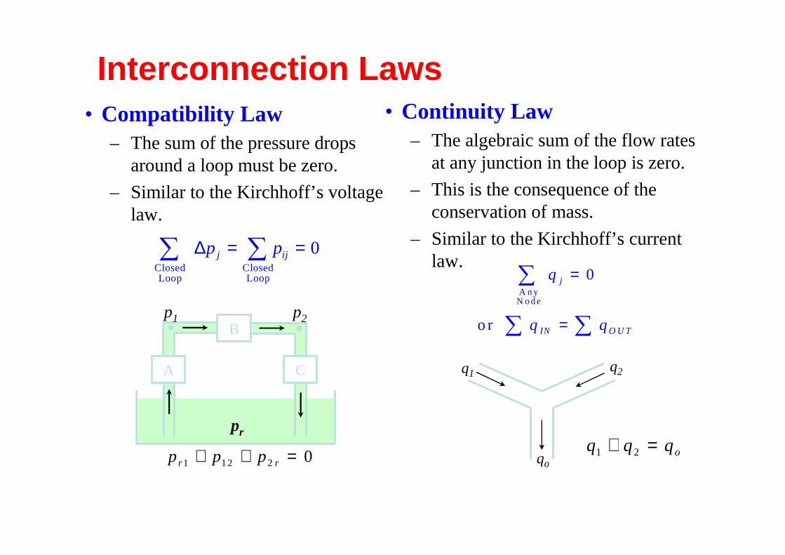
Interconnection Laws• Compatibility Law
– The sum of the pressure drops around a loop must be zero.
– Similar to the Kirchhoff’s voltage law.
• Continuity Law– The algebraic sum of the flow rates
at any junction in the loop is zero.
– This is the consequence of the conservation of mass.
– Similar to the Kirchhoff’s current law.
∆p pj ij= =∑∑ClosedLoop
ClosedLoop
0
q
q q
j
IN O U T
=
=
∑
∑∑
0A n y
N ode
or
q1 q2
qo
q q qo1 2+ =
A
B
C
pr
p1 p2
p p pr r1 12 2 0+ + =
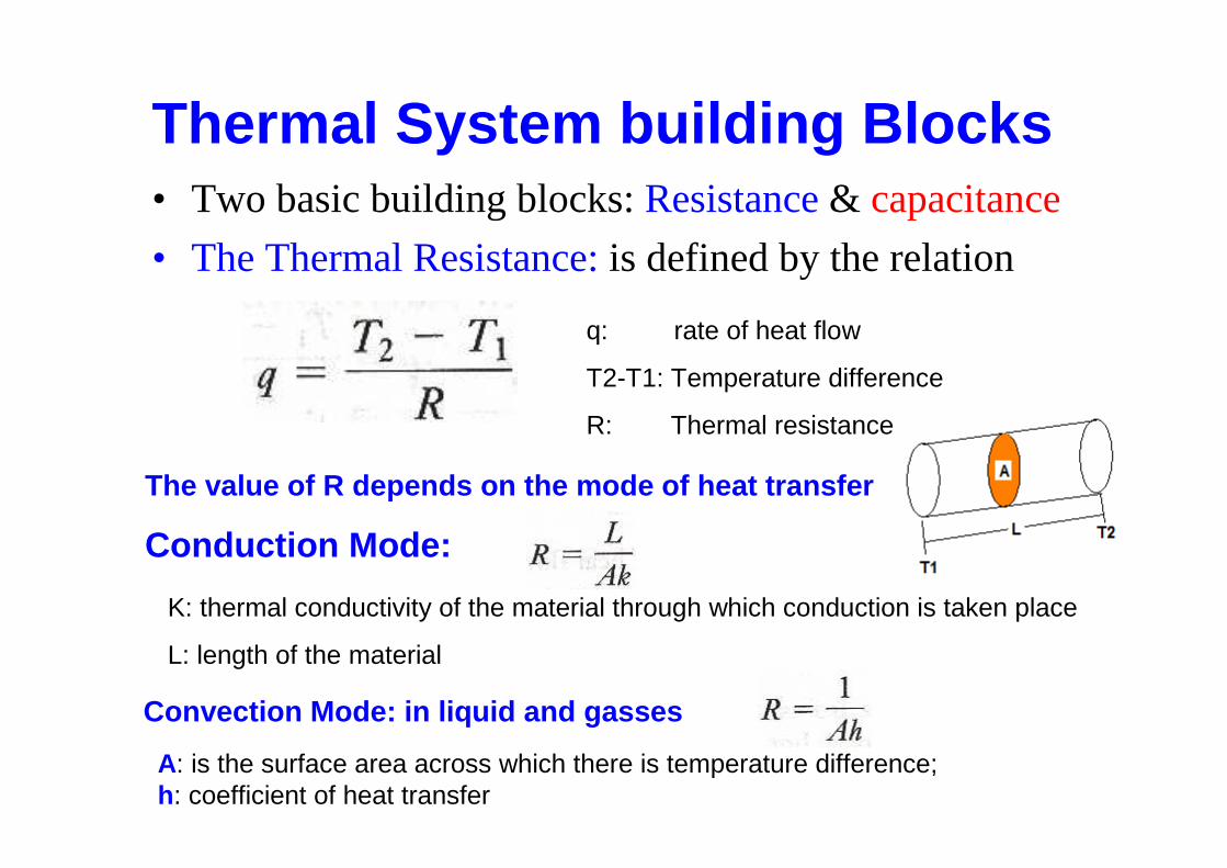
Thermal System building Blocks• Two basic building blocks: Resistance& capacitance
• The Thermal Resistance:is defined by the relation
q: rate of heat flow
T2-T1: Temperature difference
R: Thermal resistance
The value of R depends on the mode of heat transfer
Conduction Mode:
Convection Mode: in liquid and gasses
K: thermal conductivity of the material through which conduction is taken place
L: length of the material
A: is the surface area across which there is temperature difference; h: coefficient of heat transfer
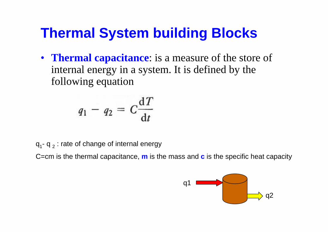
• Thermal capacitance: is a measure of the store of internal energy in a system. It is defined by the following equation
Thermal System building Blocks
q1- q 2 : rate of change of internal energy
C=cm is the thermal capacitance, m is the mass and c is the specific heat capacity
q1
q2
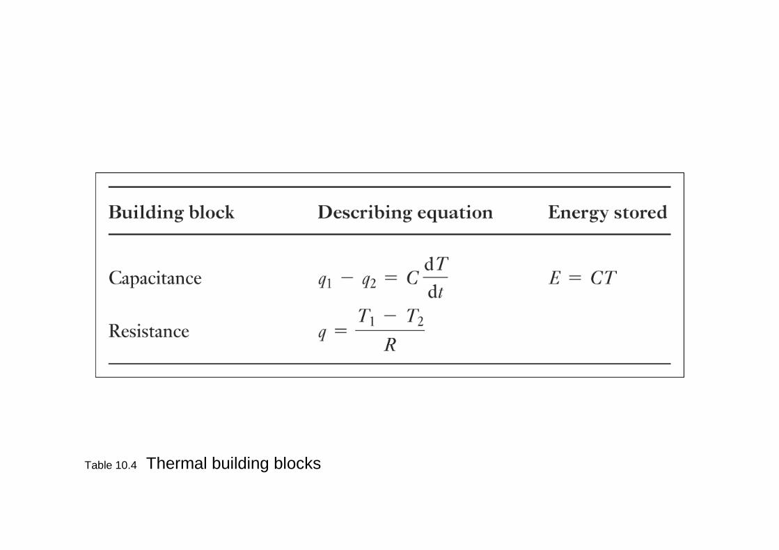
Table 10.4 Thermal building blocks
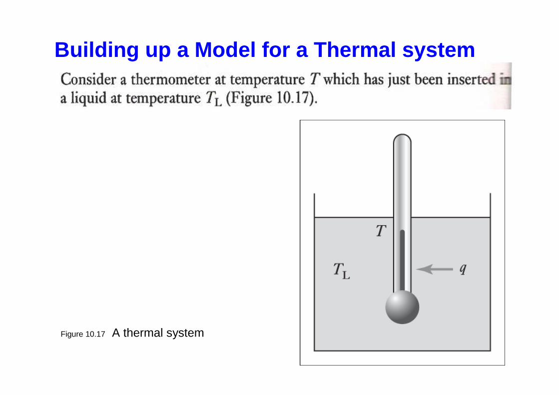
Figure 10.17 A thermal system
Building up a Model for a Thermal system
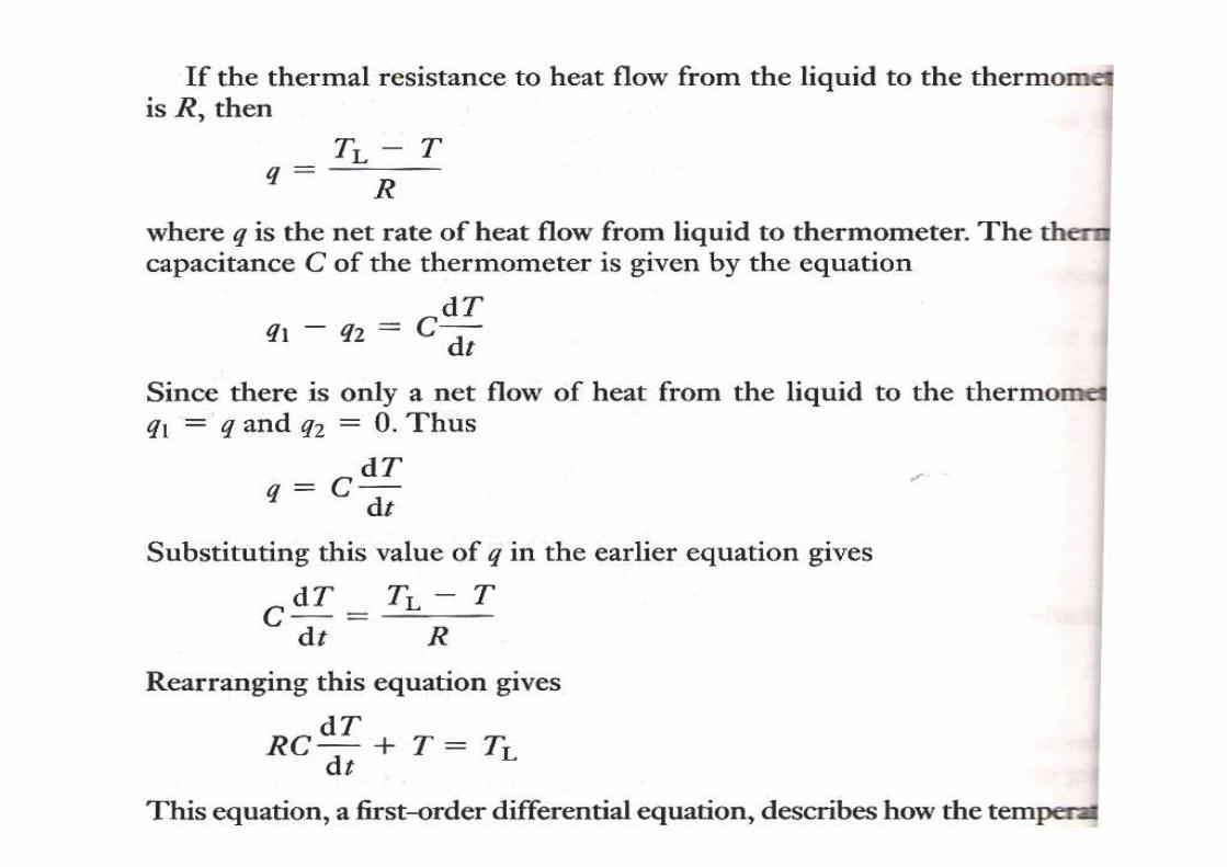
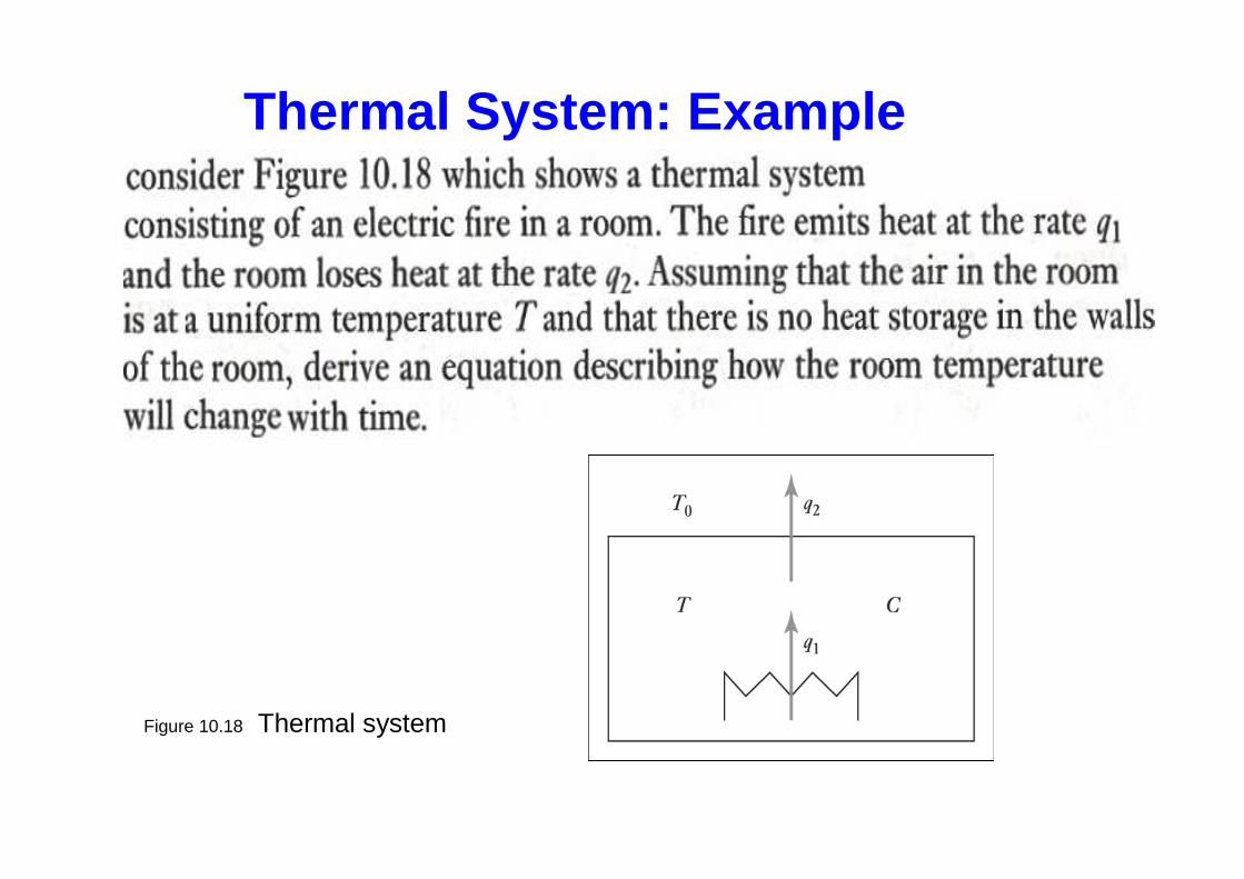
Figure 10.18 Thermal system
Thermal System: Example
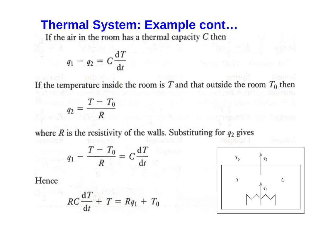
Thermal System: Example cont…
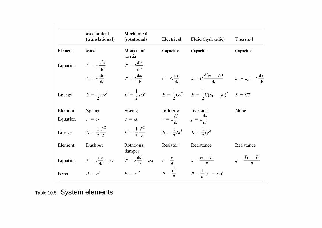
Table 10.5 System elements