Embed Size (px)
Citation preview
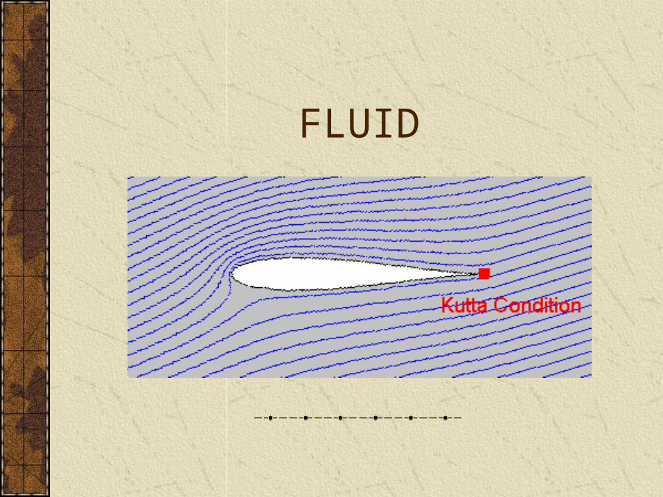
FLUID
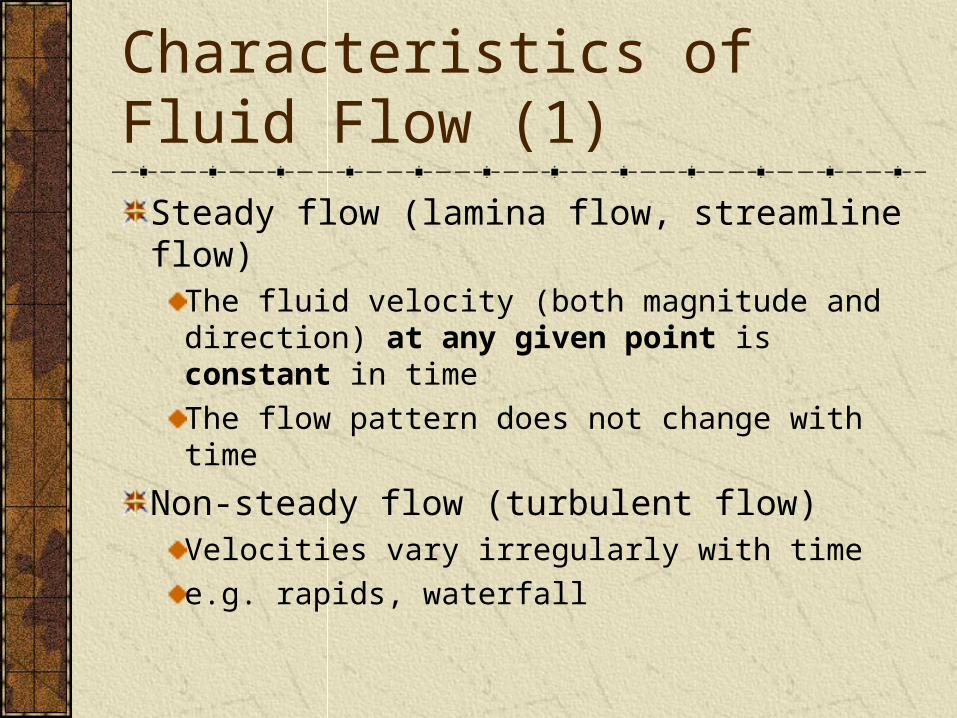
Characteristics of Fluid Flow (1)
Steady flow (lamina flow, streamline flow)The fluid velocity (both magnitude and direction) at any given point is constant in time
The flow pattern does not change with time
Non-steady flow (turbulent flow)Velocities vary irregularly with time
e.g. rapids, waterfall
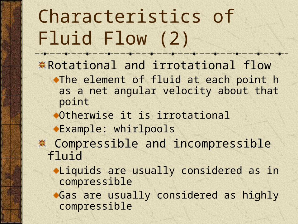
Rotational and irrotational flowThe element of fluid at each point has a net angular velocity about that pointOtherwise it is irrotationalExample: whirlpools
Compressible and incompressible fluidLiquids are usually considered as incompressibleGas are usually considered as highly compressible
Characteristics of Fluid Flow (2)
Viscous and non-viscous fluidViscosity in fluid motion is the analog of friction in the motion of solids
It introduces tangential forces between layers of fluid in relative motion and results in dissipation of mechanical energy
Characteristics of Fluid Flow (3)
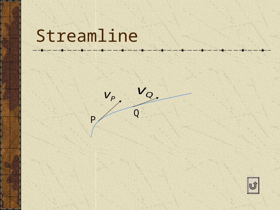
Streamline
A streamline is a curve whose tangent at any point is along the velocity of the fluid particle at that point It is parallel to the velocity of the fluid particles at every point No two streamlines can cross one another In steady flow the pattern of streamlines in a flow is stationary with time

Change of speed of flow with cross-sectional area
If the same mass of fluid is to pass through every section at any time, the fluid speed must be higher in the narrower region
Therefore, within a constriction the streamlines must get closer together
Kinematics (1)
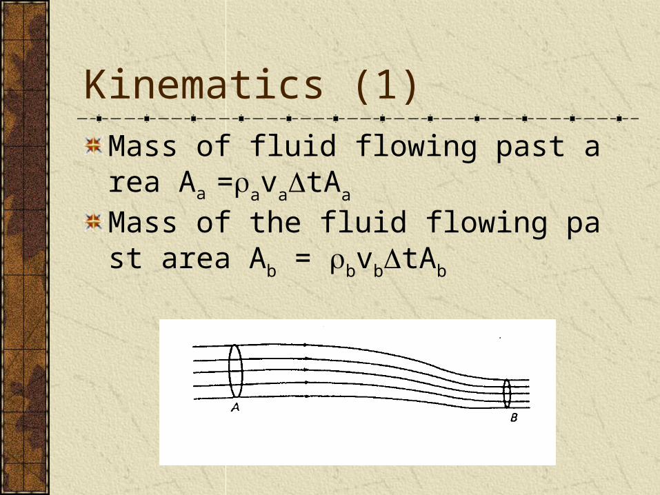
Mass of fluid flowing past area Aa =avatA
a
Mass of the fluid flowing past area Ab = bv
btAb
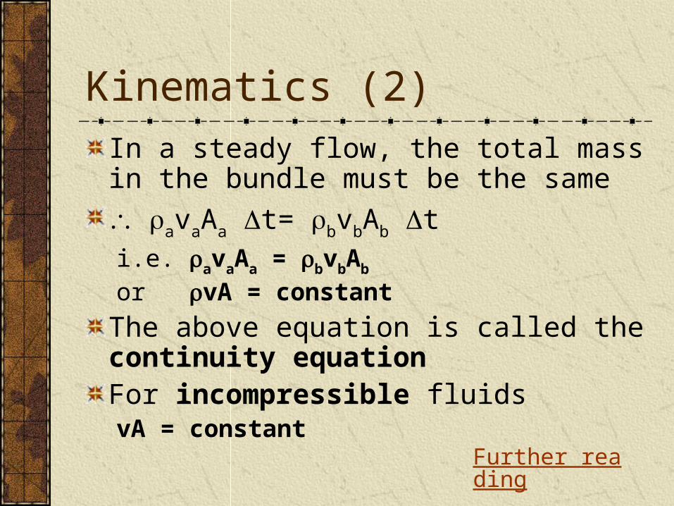
In a steady flow, the total mass in the bundle must be the same
avaAa t= bvbAb ti.e. avaAa = bvbAb or vA = constant
The above equation is called the continuity equation For incompressible fluids vA = constant
Kinematics (2)
Further reading
Static liquid pressure
The pressure at a point within a liquid acts in all directions
The pressure depends on the density of the liquid and the depth below the surfaceP = gh
Further reading
Bernoulli’s equation
Bernoulli’s equationThis states that for an incompressible, non-viscous fluid undergoing steady lamina flow, the pressure plus the kinetic energy per unit volume plus the potential energy per unit volume is constant at all points on a streamline
i.e. constant 221 ghvp
Derivation of Bernoulli’s equation (1)
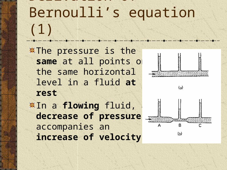
The pressure is the same at all points on the same horizontal level in a fluid at rest
In a flowing fluid, a decrease of pressure accompanies an increase of velocity
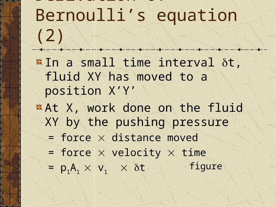
In a small time interval t, fluid XY has moved to a position X’Y’
At X, work done on the fluid XY by the pushing pressure= force distance moved
= force velocity time
= p1A1 v1 t
Derivation of Bernoulli’s equation (2)
figure
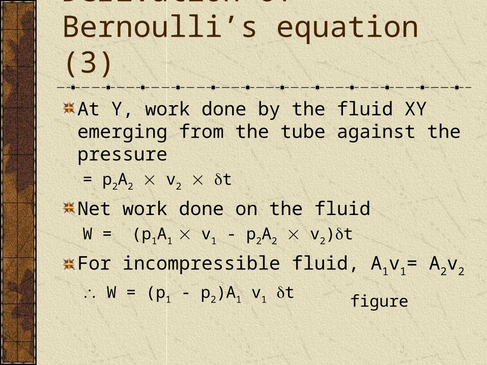
At Y, work done by the fluid XY emerging from the tube against the pressure= p2A2 v2 t
Net work done on the fluidW = (p1A1 v1 - p2A2 v2)t
For incompressible fluid, A1v1= A2v2
W = (p1 - p2)A1 v1 t
Derivation of Bernoulli’s equation (3)
figure
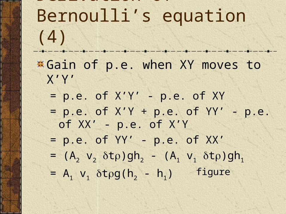
Gain of p.e. when XY moves to X’Y’= p.e. of X’Y’ - p.e. of XY
= p.e. of X’Y + p.e. of YY’ - p.e. of XX’ - p.e. of X’Y
= p.e. of YY’ - p.e. of XX’
= (A2 v2 t)gh2 - (A1 v1 t)gh1
= A1 v1 tg(h2 - h1)
Derivation of Bernoulli’s equation (4)
figure
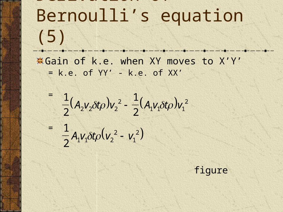
Gain of k.e. when XY moves to X’Y’= k.e. of YY’ - k.e. of XX’
=
=
Derivation of Bernoulli’s equation (5)
1
2
1
22 2 22
1 1 12A v t v A v t v
1
2 1 1 22
12A v t v v
figure
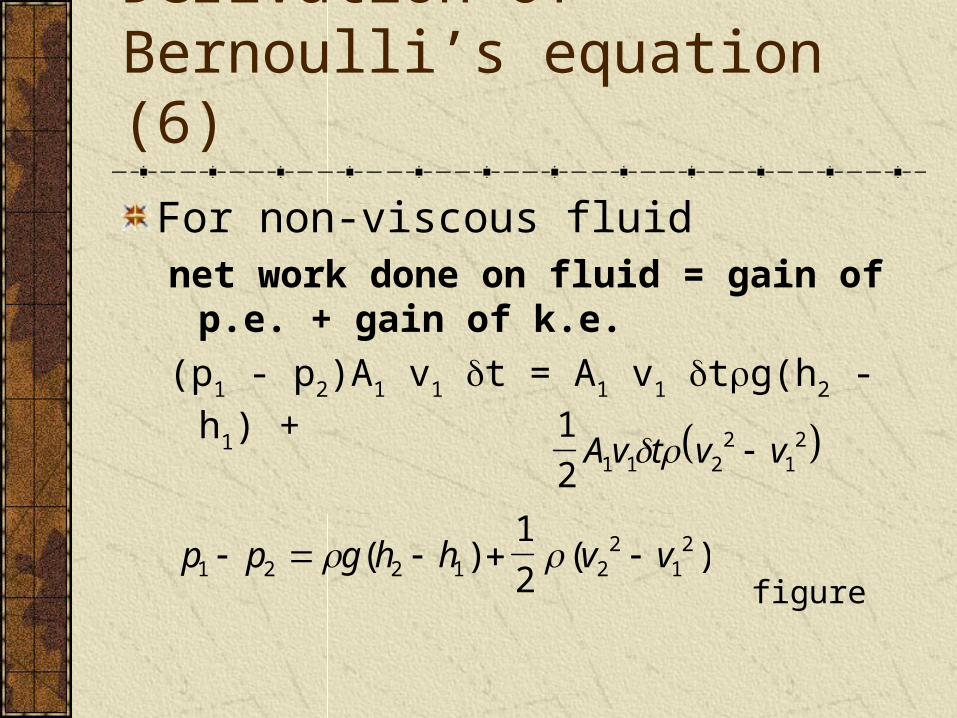
For non-viscous fluidnet work done on fluid = gain of p.e. + gain of
k.e.
(p1 - p2)A1 v1 t = A1 v1 tg(h2 - h1) +
Derivation of Bernoulli’s equation (6)
1
2 1 1 22
12A v t v v
p p g h h v v1 2 2 1 22
121
2 ( ) ( )
figure
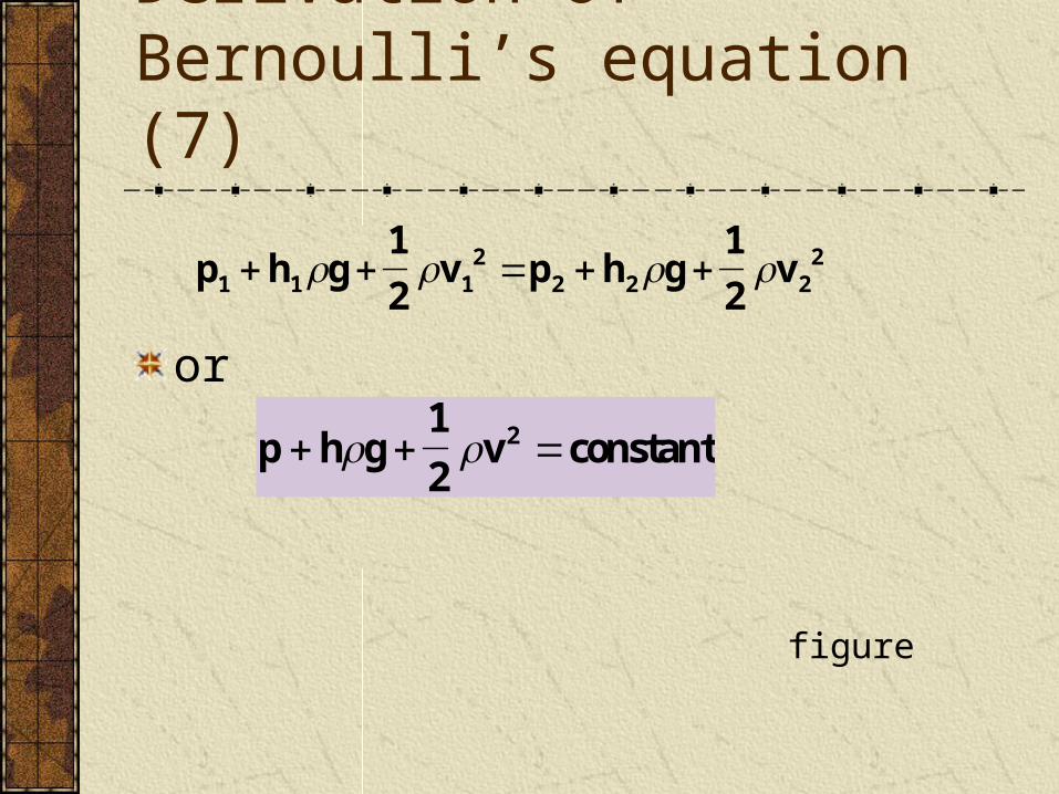
or
Derivation of Bernoulli’s equation (7)
p h g1
2v p h g
1
2v1 1 1
22 2 2
2
p h g1
2v constant2
figure
Assumptions made in deriving the equationNegligible viscous force
The flow is steady
The fluid is incompressible
There is no source of energy
The pressure and velocity are uniform over any cross-section of the tube
Derivation of Bernoulli’s equation (8)
Further reading
Applications of Bernoulli principle (1)
Jets and nozzlesBernoulli’s equation suggests that for fluid flow where the potential energy change hg is very small or zero, as in a horizontal pipe, the pressure falls when the velocity rises
The velocity increases at a constriction and this creates a pressure drop. The following devices make use of this effect in their action
Bunsen burnerThe coal gas is made to pass a constriction before entering the burner The decrease in cross-sectional area causes a sudden increase in flow speed The reduction in pressure causes air to be sucked in from the air hole The coal gas is well mixed with air before leaving the barrel and this enables complete combustion
Applications of Bernoulli principle (2)
Carburettor of a car engine The air first flows through a filter which removes dust and particles It then enters a narrow region where the flow velocity increases The reduced pressure sucks the fuel vapour from the fuel reservoir, and so the proper air-fuel mixture is produced for the internal combustion engine
Applications of Bernoulli principle (3)
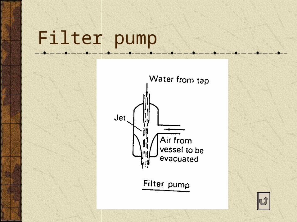
Filter pumpThe velocity of the running water increases at the constriction
The surrounding air is dragged along by the water jet and this causes a drop in pressure
Air is then sucked in from the vessel to be evacuated
Applications of Bernoulli principle (4)
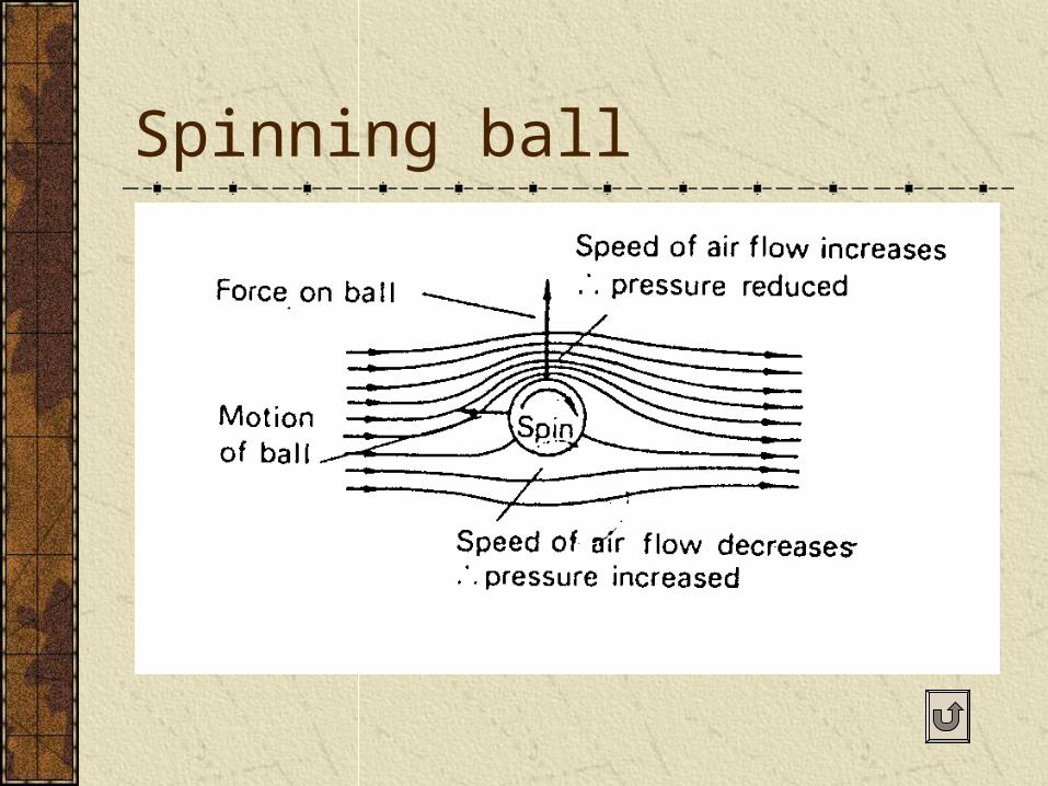
Spinning ball
If a tennis ball is `cut’ it spins as it travels through the air and experiences a sideways force which causes it to curve in flight This is due to air being dragged round by the spinning ball, thereby increasing the air flow on one side and decreasing it on the other A pressure difference is thus created
Further readingfigure
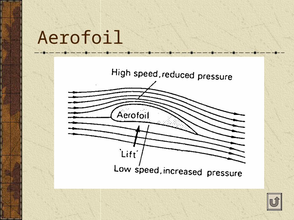
Aerofoil
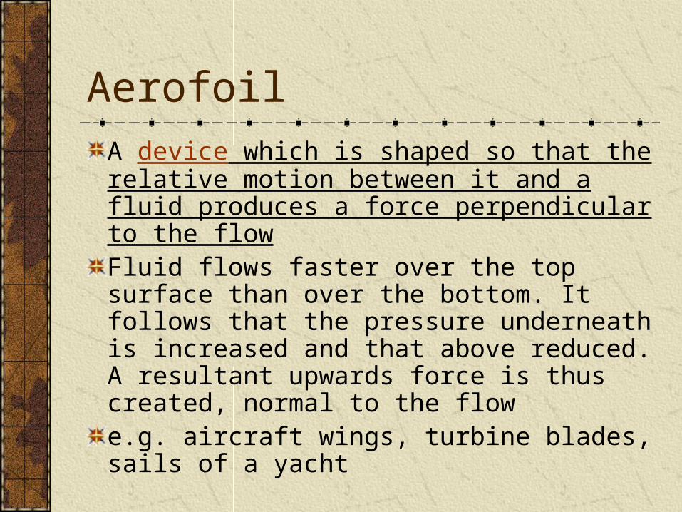
A device which is shaped so that the relative motion between it and a fluid produces a force perpendicular to the flowFluid flows faster over the top surface than over the bottom. It follows that the pressure underneath is increased and that above reduced. A resultant upwards force is thus created, normal to the flow e.g. aircraft wings, turbine blades, sails of a yacht
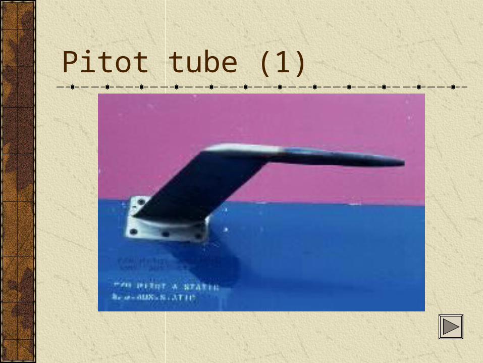
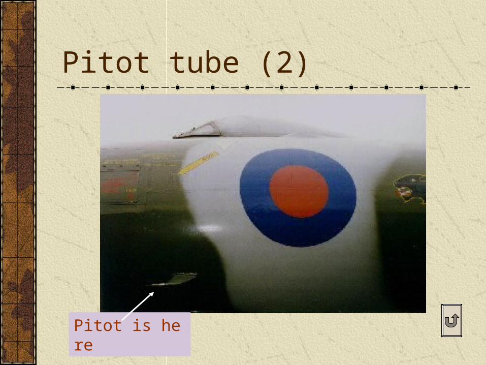
Pitot tube (1)
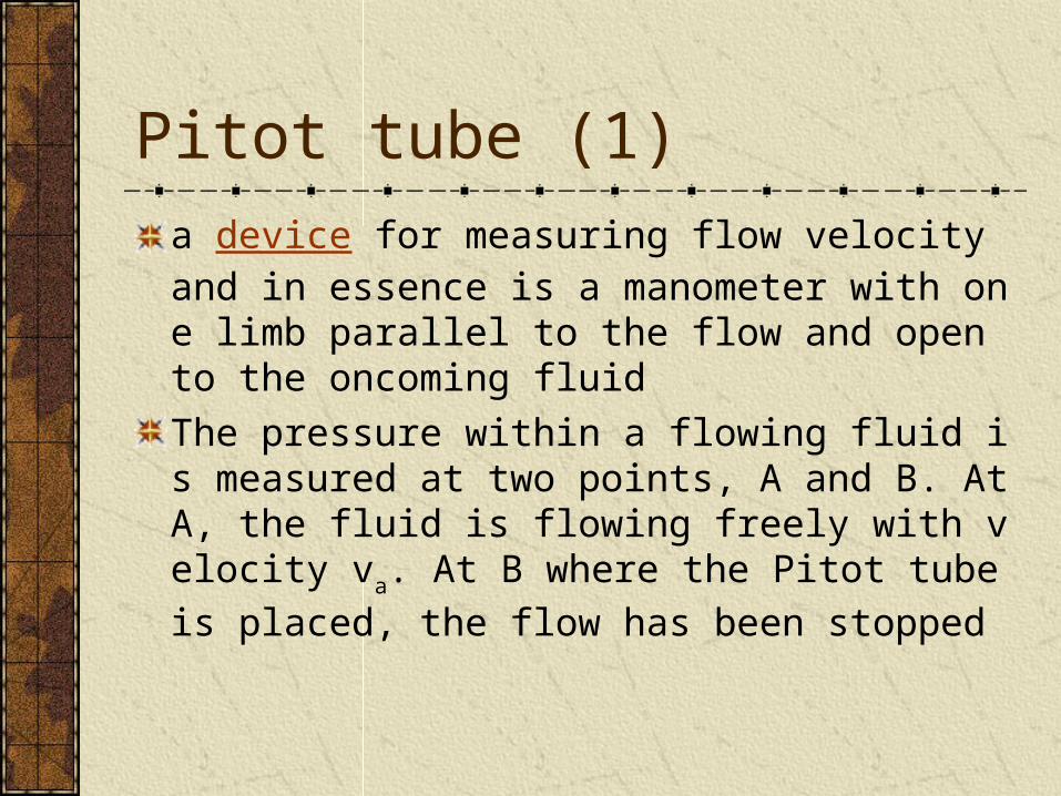
a device for measuring flow velocity and in essence is a manometer with one limb parallel to the flow and open to the oncoming fluid
The pressure within a flowing fluid is measured at two points, A and B. At A, the fluid is flowing freely with velocity va. At B where the Pitot tube is pl
aced, the flow has been stopped
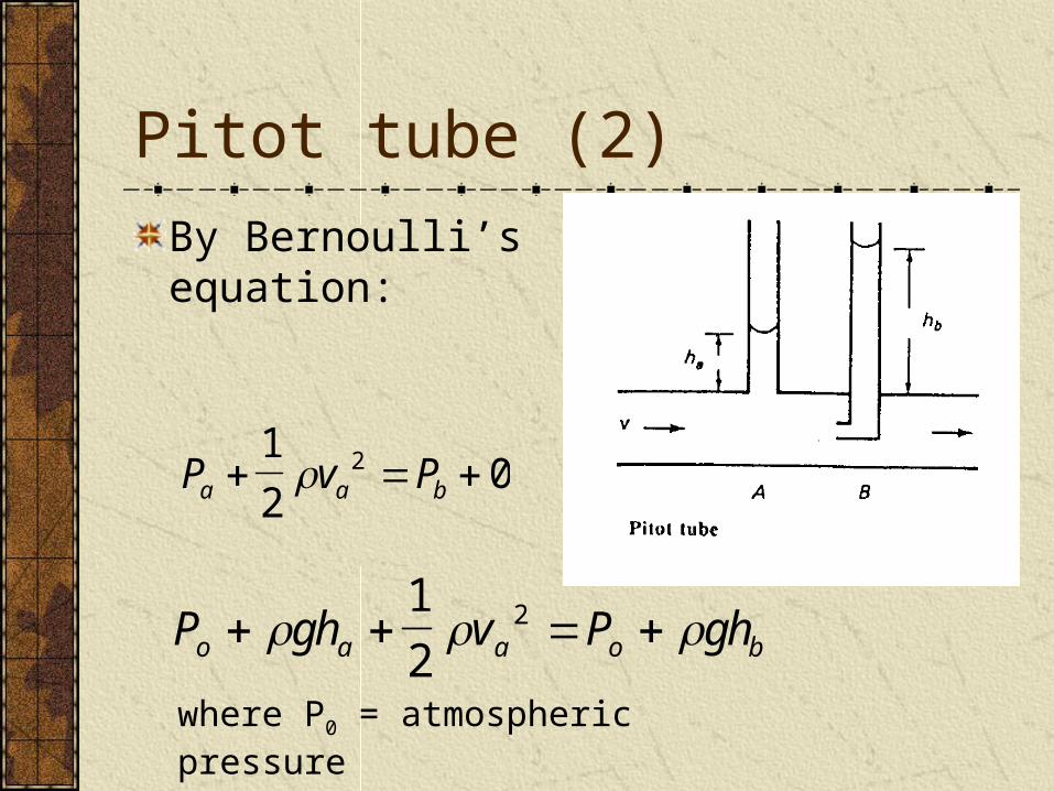
By Bernoulli’s equation:
Pitot tube (2)
P v Pa a b 1
202
P gh v P gho a a o b 1
22
where P0 = atmospheric pressure
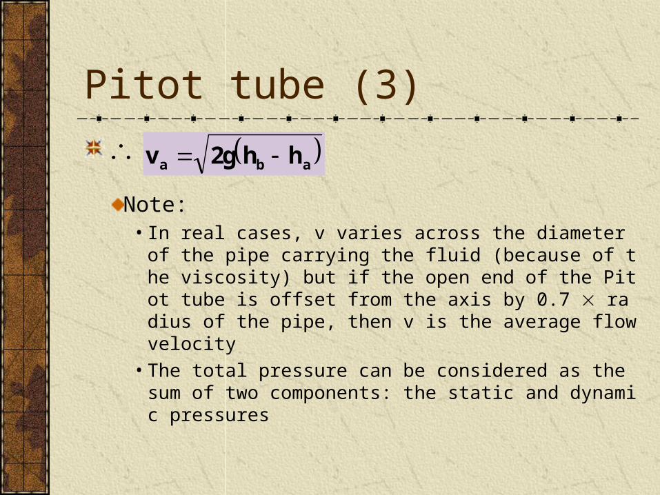
Note:• In real cases, v varies across the diameter of the pipe
carrying the fluid (because of the viscosity) but if the open end of the Pitot tube is offset from the axis by 0.7 radius of the pipe, then v is the average flow velocity
• The total pressure can be considered as the sum of two components: the static and dynamic pressures
Pitot tube (3)
v 2g h ha b a

A moving fluid exerts its total pressure in the direction of flow. In directions at right angles to the flow, the fluid exerts its static pressure only figures
P p gh vT ( ) 12
2
Total Static Dynamic
pressure pressure pressure
Pitot tube (4)
Further reading: paragraph of ‘Pitot Static System’ near the bottom of the page
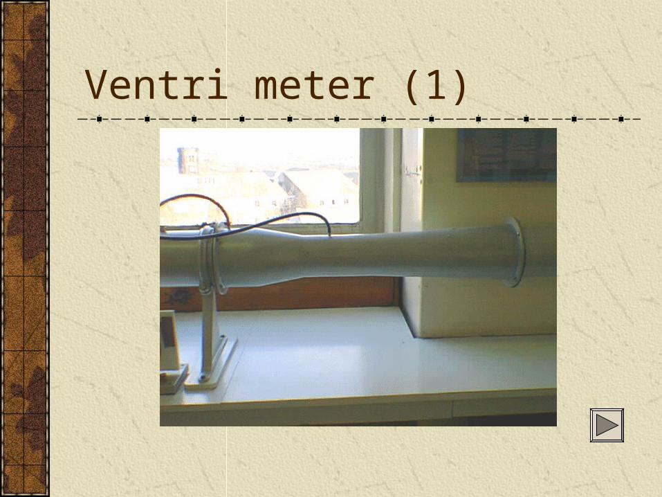
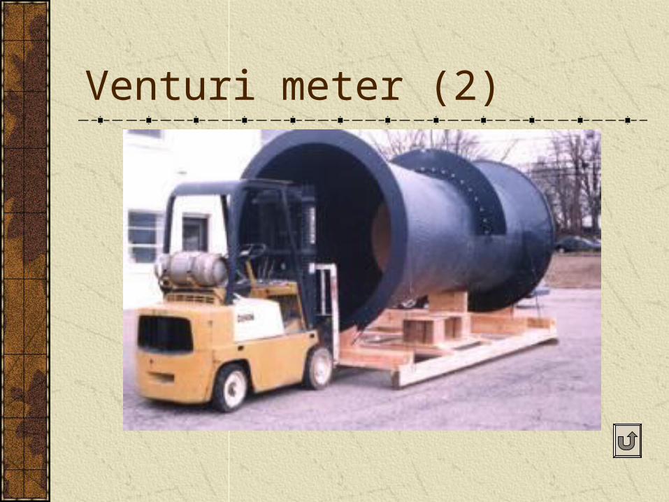
Venturi meter (1)
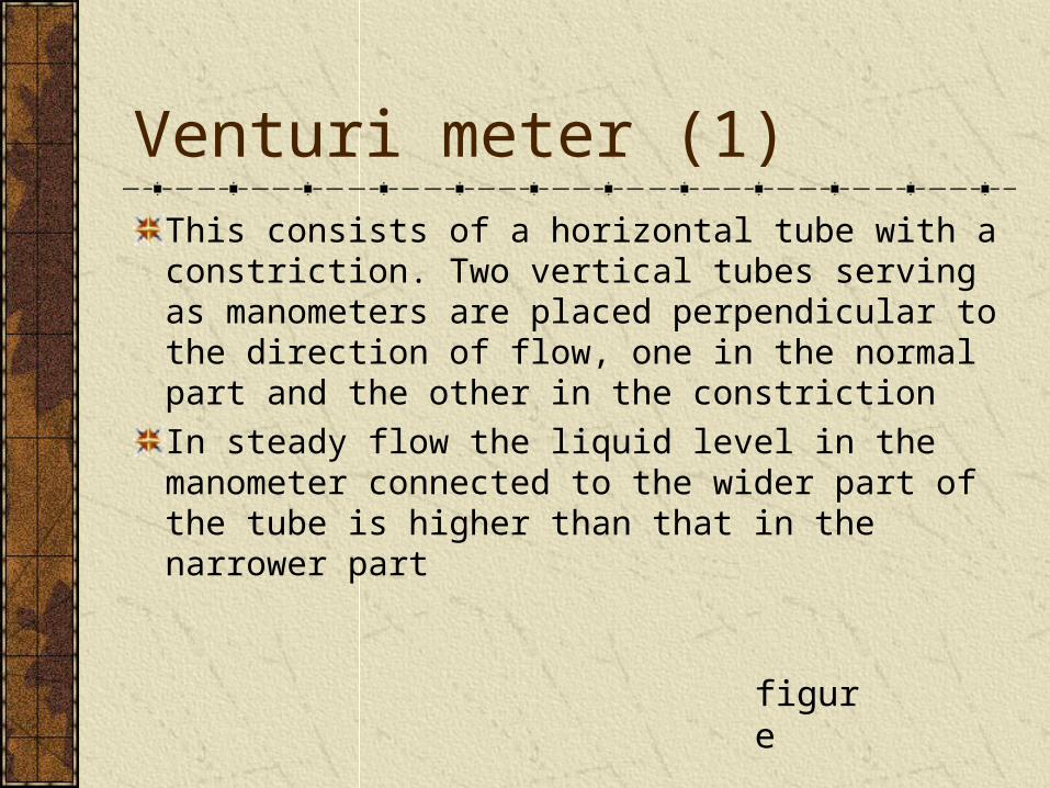
This consists of a horizontal tube with a constriction. Two vertical tubes serving as manometers are placed perpendicular to the direction of flow, one in the normal part and the other in the constriction
In steady flow the liquid level in the manometer connected to the wider part of the tube is higher than that in the narrower part
figure
Venturi meter (2)
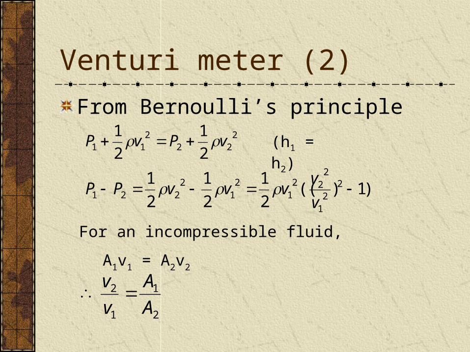
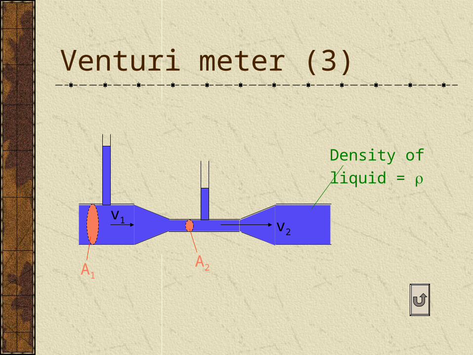
From Bernoulli’s principle2
222
11 2
1
2
1vPvP (h1 = h2)
)1)((2
1
2
1
2
1 22
1
222
12
12
221 v
vvvvPP
For an incompressible fluid,
A1v1 = A2v2
2
1
1
2
A
A
v
v
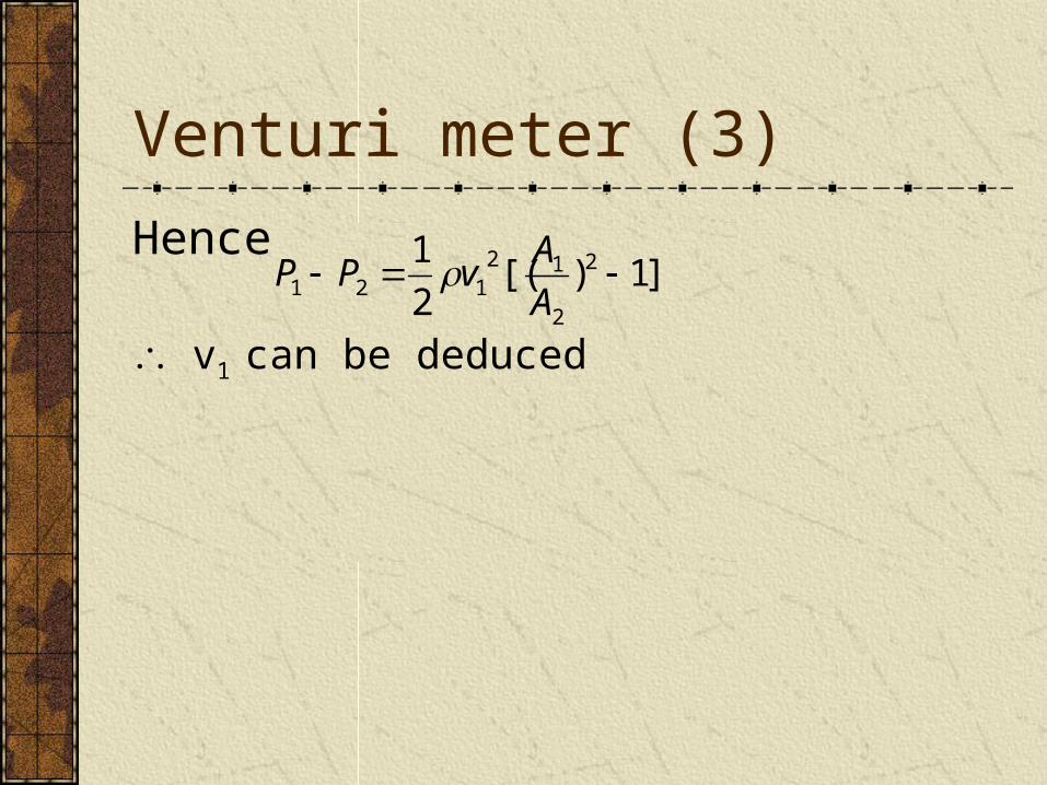
Hence
Venturi meter (3)
]1)[(2
1 2
2
12121 A
AvPP
v1 can be deduced

Streamline
PQ
vPvQ
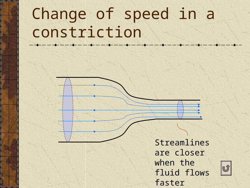
Change of speed in a constriction
Streamlines are closer when the fluid flows faster
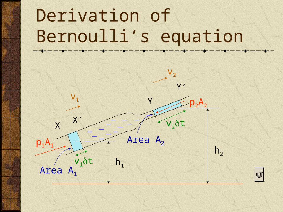
Derivation of Bernoulli’s equation
X
Y
X’
Y’v1
p1A1
p2A2
v1t
v2t
Area A1
Area A2
v2
h1
h2
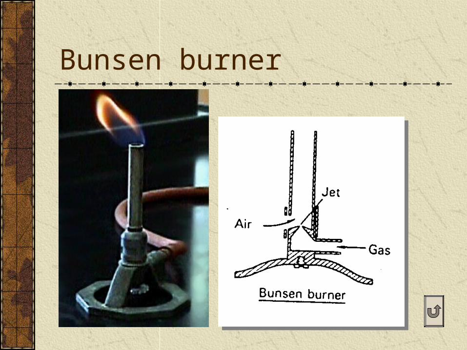
Bunsen burner
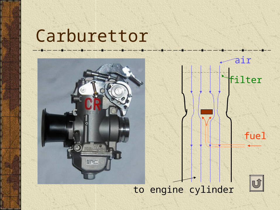
Carburettor
fuel
air
filter
to engine cylinder
Filter pump
Spinning ball
Aerofoil
Pitot tube (1)
Pitot tube (2)
Pitot is here
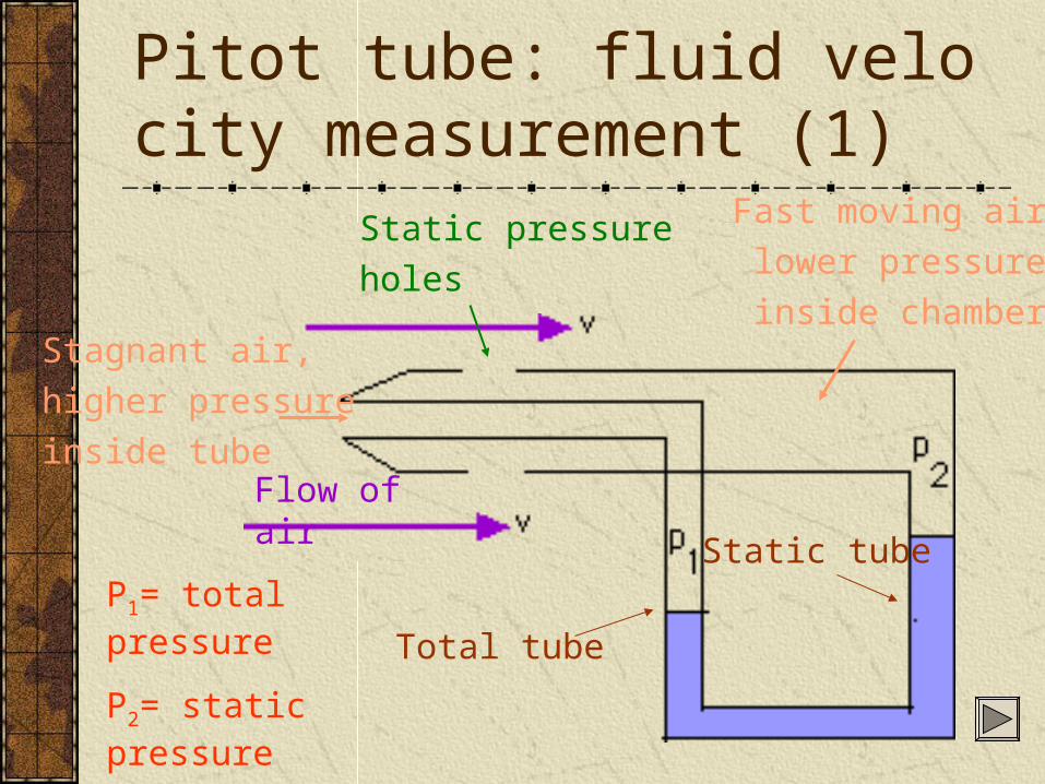
Pitot tube: fluid velocity measurement (1)
Flow of air
Stagnant air,
higher pressure
inside tube
Fast moving air,
lower pressure
inside chamber
Total tube
Static tube
Static pressure
holes
P1= total pressure
P2= static pressure
P2 – P1 = ½(v2)
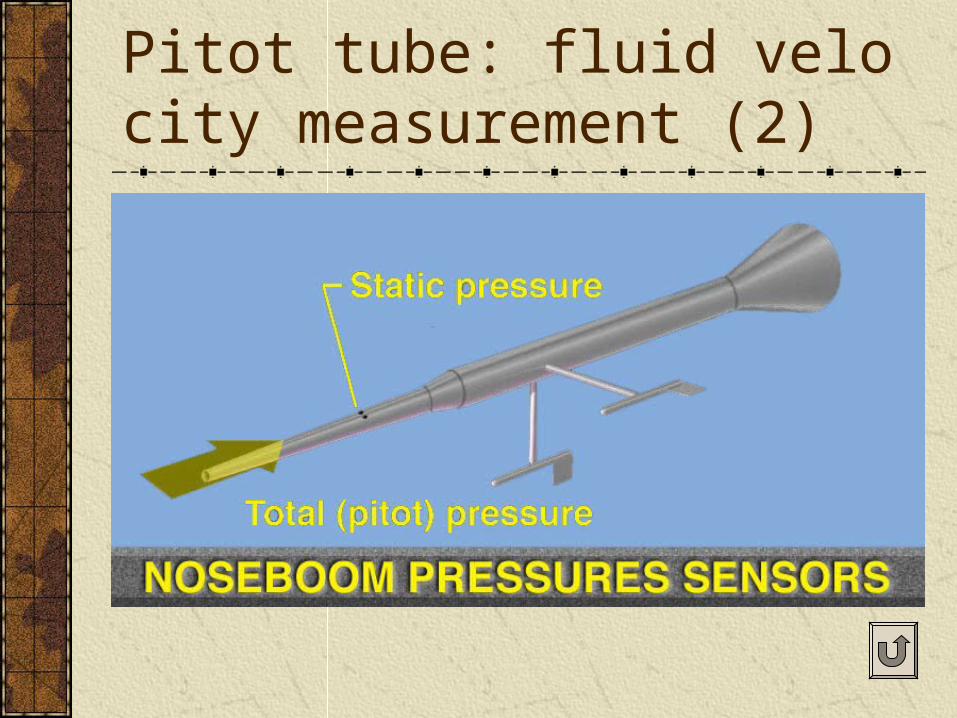
Pitot tube: fluid velocity measurement (2)
Ventri meter (1)
Venturi meter (2)
Venturi meter (3)
A1A2
v1 v2
Density of
liquid =