Embed Size (px)
Citation preview
1210 IEEE TRANSACTIONS ON ENERGY CONVERSION, VOL. 26, NO. 4, DECEMBER 2011
Model Based-Energy Control of a Solar PowerPlant With a Supercapacitor forGrid-Independent Applications
Phatiphat Thounthong, Member, IEEE
Abstract—This paper proposes a design for a renewable-energyhybrid power plant that is fed by a photovoltaic (PV) source with asupercapacitor (SC) storage device and is suitable for distributedgeneration applications. The PV array is used as the main genera-tor, and the SC functions as an auxiliary source for supplying the(transient and steady-state) power deficiency of the PV array. Forhigh-power applications, four-phase parallel boost converters andfour-phase parallel bidirectional converters are implemented as aPV converter and a storage device, respectively. A reduced-ordermathematical model of the PV and SC converters is described forthe control of the power plant. Using a nonlinear approach basedon the flatness property, we propose a simple solution to the dy-namic, stabilization, and robustness problems in the hybrid powersystem. This is the key innovative contribution of this research pa-per. We analyze a prototype small-scale power plant composed of a0.8-kW PV array and a 100-F SC module. The experimental resultsauthenticate the excellent control algorithm during load cycles.
Index Terms—Converters, flatness, hybrid source, nonlinearcontrol, photovoltaic (PV), supercapacitor (SC).
I. INTRODUCTION
CURRENTLY, renewable energy is receiving greater atten-tion as a sustainable alternative to more traditional energy
sources. One of these environmentally friendly energy sourcesis solar energy; however, there are still some severe concernsabout several sources of renewable energy and their implemen-tation, e.g., 1) capital costs and 2) their intermittent power pro-duction, called the “intermittency problem.” The intermittencyproblem of solar energy is that solar panels cannot producepower steadily because their power production rates changewith seasons, months, days, hours, etc. If there is no sunlight,no electricity will be produced from the photovoltaic (PV) cell.
To overcome the intermittency problem, a storage mediumor electrical energy carrier [a battery or a supercapacitor (SC)]
Manuscript received March 24, 2011; revised July 6, 2011; acceptedSeptember 6, 2011. Date of publication October 10, 2011; date of current versionNovember 23, 2011. This work was supported in part by the research program incooperation with the Thai–French Innovation Institute, King Mongkut’s Univer-sity of Technology North Bangkok with the Institut National Polytechnique deLorraine, Nancy University, under the “Franco-Thai on Higher Education andResearch Joint Project year: 2009–2010,” and in part by the Thailand ResearchFund under Grant MRG5380261. Paper no. TEC-00153-2011.
The author is with the Department of Teacher Training in Electrical En-gineering (TE), King Mongkut’s University of Technology North Bangkok(KMUTNB), Bangkok 10800, Thailand (e-mail: [email protected]).
Color versions of one or more of the figures in this paper are available onlineat http://ieeexplore.ieee.org.
Digital Object Identifier 10.1109/TEC.2011.2168400
is needed. An SC storage device is preferable due to its highpower density, fast energy sourcing, and long lifetime [1]. In thenear future, the utility power system will be supplied on a largescale by solar energy sources and storage device(s) in a hybridenergy system to increase the reliability and effectiveness of theindividual components [2].
The dynamics, robustness, and stability of the operation ofhybrid power plants are of particular interest. In this work, a hy-brid power generation system is proposed and it consists of thefollowing main components: a PV source and an SC as a high-power density device. The most popular way to control powerconverters in the industry today is with a linear control struc-ture [3], [4]. The design of the linear proportional-integral (PI)controller usually proceeds by incorporating the switching modecontroller into the plant (converter). Later averaging and lin-earization enables the employ of the Laplace transform [5], [6].The PI controller may then be designed for a certain phase mar-gin, normally around 30–60◦. Because the switching model ofthe hybrid power plant (power electronic converters) is nonlin-ear, it is natural to apply model-based nonlinear control strate-gies that directly compensate for system nonlinearity withoutrequiring a linear approximation [7].
Currently, many modeling and linear or nonlinear control as-pects, including classical state-space or transfer approaches [8],[9], self-tuning methods or sliding mode control [10], the ex-act linearization technique [11], adaptive control [12], or fuzzylogic-based control [13], have been extensively studied for non-linear power electronic applications. Flatness-based control hasrecently been studied in many applications because it is ap-propriate for robustness, predictive control, trajectory planning,and constraint handling. Based on the flatness approach, thestate feedback can be chosen in such a way that the closed-loopdynamic behavior is linear [14]. Flat systems are linearizable inthe quasi-static state feedback. When used for tracking, quasi-static state feedback is very useful.
The flatness theory was introduced by Fliess et al. [14] in1995. Recently, these ideas have been used in a variety of non-linear systems across the various engineering disciplines, in-cluding the following applications: the control of an invertedpendulum and a vertical take-off and landing aircraft [15]; theprocess of a stirred tank chemical reactor [16]; the control ofvehicle steering [17]; the control of a high-speed linear axisdriven by pneumatic muscle actuators [18]; the control of cath-ode pressure and the oxygen excess ratio of a proton exchangemembrane (PEM) fuel cell system [19]; the steering control ofa two-level quantum system [20]; the reactive power and the
0885-8969/$26.00 © 2011 IEEE

THOUNTHONG: MODEL BASED-ENERGY CONTROL OF A SOLAR POWER PLANT WITH A SUPERCAPACITOR 1211
Fig. 1. Power versus current characteristics and voltage versus current char-acteristics based on a 200-W PV module by the Ekarat Solar at fixed ambienttemperature and variable insolation (1000 and 600 W·m−2 ).
dc voltage tracking control of a three-phase voltage source con-verter [21]; the control of open-channel flow in an irrigationcanal [22]; and the current control for three-phase three-wireboost converters [23].
We now study an uncomplicated design of a control system ofthe PV/SC power plant based upon the physical structure of themodel. The main contribution of this paper is to present the dif-ferential flatness-based control approach of a solar power gener-ation system with an SC storage device. In particular, we do notrestrict ourselves to linear control techniques at an equilibriumpoint. This is the novel work in this domain. The remaining ofthe paper is structured as follows: the next section describes thehybrid energy system and the power plant model that is studiedin this work. In Section III, the proposed energy managementalgorithm is presented. In Section IV, a proof of the flat systemconsisting of the solar energy power plant, the control laws, andthe system stability is presented. In Section V, the test bench re-sults for the proposed system are presented. Finally, this paperends with concluding remarks for further study in Section VI.
II. POWER SOURCE CHARACTERISTICS
A. Photovoltaic
The PV effect is a basic physical process through which solarenergy is converted directly into electrical energy. The physicsof a PV cell, or solar cell, is similar to the classical p–n junctiondiode. The V–I and P–I characteristic curves of the PV modelused in this study (200-W PV Module by the Ekarat Solar Com-pany) under different irradiances (at 25 ◦C) are given in Fig. 1.As shown in Fig. 1, the higher the irradiance, the larger theshort-circuit current ISC and the open-circuit voltage VOC . As aresult, the output PV power will also be larger.
Remark 1: PV power systems require some specific estima-tion algorithms to deliver the maximum power point (MPP)[24], [25]. Because of the typical low-efficiency characteristicsof PV panels, it is very important to deliver the maximum in-stantaneous power from these energy sources to the load with
minimum power conversion for space or terrestrial applications.Temperature also plays an important role in the PV array per-formance. The lower the temperature, the higher the maximumpower and the larger the open-circuit voltage. It is obligatoryto use dc/dc or dc/ac converters with effective MPP tracking(MPPT) techniques [26].
B. Supercapacitor
The SC (or double-layer capacitor or ultracapacitor) is anemerging technology in the field of energy-storage systems.Recent breakthroughs in construction methods aimed at maxi-mizing rated capacitance have provided tremendous increasesin the energy-storage capabilities of the double-layer capaci-tor [27]. With a time constant (the product of equivalent seriesresistance (ESR) and capacitance) of 0.001–2 s for an SC, thestored energy can be extracted at a very high rate because theESR inside an SC is very small [28]. In contrast, the same-sizedbattery will not be able to supply the necessary energy in thesame time period because of the higher time constant of thebattery [27], [29].
The operating voltage of an SC changes linearly with timeduring constant current operation so that the state-of-chargecan be precisely estimated. In addition, the highly reversibleelectrostatic charge storage mechanism in SCs does not lead tothe volume changes observed in batteries with electrochemicaltransformations of active masses. This volume change usuallylimits the lifetime cycle of batteries to several hundred cycles,whereas SCs have demonstrated from hundreds of thousands tomany millions of full charge/discharge cycles [30], [31].
The SC bank is always connected to the dc bus by means ofa two-quadrant dc/dc converter (bidirectional converter). Fig. 2presents the transient response of an SC converter interfacingbetween the dc bus and the SC bank (SAFT SC module: 292 F,30 V) [32]. The initial voltage of the SC bank is 30 V. The SCcurrent set-point (reference) is Ch2 and the measured SC currentis Ch4. The dynamic response of the SC auxiliary source is veryfast and can discharge from 0 to 50 A in 0.4 ms.
Remark 2: To operate the SC module, its module voltage islimited to an interval [VSCMin , VSCMax ]. The higher VSCMaxvalue of this interval corresponds to the rated voltage of thestorage device. In general, the lower VSCMin value is chosen asVSCMax /2, where the remaining energy in the SC bank is only25% and the SC discharge becomes ineffective [32].
III. SOLAR POWER PLANT
A. Structure of the Studied Power Converters
Low-voltage, high-current (power) converters are needed be-cause of the electrical characteristics of the PV cell and theSC bank. A classical boost converter is often used as a PVconverter [33], and a classical two-quadrant (bidirectional) con-verter is often used as an SC or battery converter [27]. However,the classical converters will be limited when the power increasesor at higher step-up ratios. Therefore, the use of parallel powerconverters (multiphase converters in parallel) with interleavingmay offer better performance in terms of dynamics [34], because

1212 IEEE TRANSACTIONS ON ENERGY CONVERSION, VOL. 26, NO. 4, DECEMBER 2011
Fig. 2. SC current response to a 0–50 A step (discharging).
Fig. 3. Proposed circuit diagram of the distributed generation system suppliedby a PV and SC, where pLoad ( = vBus × iLoad ), vBus , and iLoad are the loadpower, the dc-bus voltage, and the dc-bus load current, respectively. pPV ( =vPV × iPV ), vPV , and iPV are the PV power, voltage, and current, respectively.pSC ( = vSC × iSC ), vSC , and iSC are the SC power, voltage, and current,respectively. pPVo and pSCo are the output powers to the dc link from theconverters of the PV array and the SC, respectively.
of smaller inductor and capacitor sizes. Next, Fig. 3 depicts theproposed hybrid source structure. The PV converter combinesfour-phase parallel boost converters with interleaving, and theSC converter employs four-phase parallel bidirectional convert-ers with interleaving.
B. Power Regulation Loops of the Proposed Power Plant
For safety and dynamics, the PV and SC converters are pri-marily controlled by inner current regulation loops (or powerregulation loops), as depicted in Figs. 4 and 5 [32]. These powercontrol loops are supplied by two reference signals: the SCpower reference pSCREF and the PV power reference pPVREF ,generated by the control laws presented later.
Fig. 4. Photovoltaic power control loop.
For the PV power control, a PV power reference pPVREF isdivided by the measured photovoltaic voltage vPV , resulting ina PV current reference iPVREF . For the SC power control loop,an SC power reference pSCREF is divided by the measured SCvoltage vSC and limited to maintain the SC voltage within aninterval [VSCMin , VSCMax ], according to Remark 2 by the SCcurrent limitation function. This calculation results in an SCcurrent reference iSCREF [32].
C. Mathematical Model of the Power Plant
We assume that the PV and SC currents follow their referencevalues perfectly. Consequently,
iPV = iPVREF =pPV
vPV=
pPVREF
vPV(1)
iSC = iSCREF =pSC
vSC=
pSCREF
vSC. (2)
We only consider static losses in these converters, and rPVand rSC represent static losses in the PV and SC converters,respectively. Now, the PV array and the SC storage device func-tion as controlled current sources connected with the equivalentseries resistance that is called a reduced-order model [35].
The dc-bus capacitive energy EBus and the supercapacitiveenergy ESC can be written as
EBus =12CBusv
2Bus (3)
ESC =12CSCv2
SC . (4)
The total electrostatic energy ET stored in the dc-bus capaci-tor CBus and the SC CSC can also be written as
ET =12CBusv
2Bus +
12CSCv2
SC . (5)
Note that the total electrostatic energy ET is nearly equal tothe energy stored in the SC CSC because the SC size CSC ismuch greater than the dc-bus capacitor size CBus .
The derivative of dc-bus capacitive energy EBus is given ver-sus pPVo , pSCo , and pLoad by the following differential equation:
EBus = pPVo + pSCo − pLoad (6)

THOUNTHONG: MODEL BASED-ENERGY CONTROL OF A SOLAR POWER PLANT WITH A SUPERCAPACITOR 1213
where
pPVo = pPV − rPV
(pPV
vPV
)2
(7)
pSCo = pSC − rSC
(pSC
vSC
)2
(8)
pLoad = vBus · iLoad . (9)
Note that the derivative of dc-bus capacitive energy dEbus /dtis the power pBus flows into the dc-bus capacitor. It means thatpBus is equal to dEbus /dt (EBus)(see Fig. 3).
IV. CONTROL OF A POWER PLANT
A. Energy Balance
In the proposed system depicted in Fig. 3, there are twovoltage variables (or two energy variables) to be regulated.
1) The dc-bus energy EBus is the most important variable.2) The SC storage energy ESC is the next most important.Therefore, we propose utilizing SCs, which are the fastest
energy source in the proposed system, to supply the energy forthe dc bus [32]. In fact, we plan to functionalize the PV arrayby supplying energy only for charging the SC CSC . However,during charging, the energy from the PV cell flows throughthe dc bus to the SC bank. For this reason, the PV array ismathematically operated to supply energy for both the dc-buscapacitor CBus and the SC CSC to keep them charged.
B. Differential Flatness Property
Let us first reveal a physical property, used to establish thesystem flatness [14], [15], [36], that will be the main concept forour reference generations. The flat outputs y, the control inputvariables u, and the state variables x are defined as
y =[
y1y2
]=
[EBusET
], u =
[u1u2
]=
[pSCREFpPVDEM
],
x =[
x1x2
]=
[vBusvSC
](10)
where pPVDEM is the PV power demand. It will be generated bythe outer controller. This signal will send to an MPPT in orderto saturate the PV maximum power. It becomes the PV powerreference pPVREF , presented hereafter.
From (3) and (6), the dc-bus voltage vBus (defined as a statevariable x1 ) and the SC power (defined as a control input variableu1) can be expressed as an algebraic function
x1 =√
2y1
CBus= ϕ1 (y1) (11)
u1 = 2pSCLim
·[1 −
√1 −
(y1 + iLoad · ϕ1 (y1) − pPVo
pSCLim
)]
= ψ1 (y1 , y1) = pSCREF (12)
pSCLim =v2
SC
4rSC(13)
Fig. 5. SC power control loop.
where pSCLim is the limited maximum power from the SC con-verter.
From (5) and (6), the SC voltage vSC (defined as a statevariable x2) and the PV power pPV (defined as a control inputvariable u2) can be expressed as an algebraic function
x2 =
√2(y2 − y1)
CSC= ϕ2 (y1 , y2) (14)
u2 = 2pPVLim ·[1 −
√1 −
(y2 + iLoad · ϕ1 (y1)
pPVLim
)]
= ψ2 (y1 , y2) = pPVDEM (15)
pPVLim =v2
PV
4rPV(16)
where PPVLim is the limited maximum power from the PVconverter.
It is evident that x1 = ϕ1 (y1), x2 = ϕ2 (y1 , y2), u1 =ψ1 (y1 , y1), and u2 = ψ2 (y1 , y2). Consequently, the PV/SCpower plant can be considered a flat system [36].
C. Control Law and Stability
Let us now focus our attention on the feedback design to tracka dc-bus energy reference trajectory y1REF and a total energyreference y2REF . We aim to design a feedback law such that thetracking error (y1–y1REF , y2–y2REF ) asymptotically vanishes.Thus, the relative degree of the first input v1 and the secondinput v2 is 1. The proposed control laws [37] are
(y1 − y1REF) + K11 (y1 − y1REF) = 0 (17)
(y2 − y2REF) + K21 (y2 − y2REF) = 0. (18)
Because the SC can store enormous amount of energy, and thesupercapacitive energy is defined as a slower dynamic variablethan the dc-bus energy variable, in order to compensate fornonideal effects, an integral term is added to the control law(17). This yields
v1 = y1 = y1REF + K11 (y1REF − y1)
+ K12
t∫0
(y1REF − y1)dτ (19)

1214 IEEE TRANSACTIONS ON ENERGY CONVERSION, VOL. 26, NO. 4, DECEMBER 2011
Fig. 6. Multivariable control of a PV/SC hybrid power plant based on a differential flatness approach.
v2 = y2 = y2REF + K21 (y2REF − y2) . (20)
From (19), if we define e1 = y1 − y1REF , K11 = 2ζωn , andK12 = ω2
n , we obtain
e1 + 2ζωn · e1 + ω2n · e1 = 0. (21)
Substituting the expression for y1 from (19) into (12) givesthe equation for the closed-loop static state feedback SC power.
From (20), if we define e2 = y2 − y2REF , K21 = 1/τS , weobtain
τS · e2 + e2 = 0. (22)
Substituting the expression for y2 from (20) into (15) givesthe equation for the closed-loop static state feedback PV power.It is clear that the control system is asymptotically stable for K11 ,K12 > 0, and K21 > 0. However, based on the power electronicconstant switching frequency ωS and cascade control structure,the outer control loop (here the dc-bus energy control) mustoperate at a cutoff frequency ωE << ωC << ωS , where ωC isa cutoff frequency of the SC power loop. Once the flat outputsare stabilized, the whole system becomes exponentially stablebecause all of the variables of the system are expressed in termsof the flat outputs [36].
In Fig. 6, the proposed control algorithm of the renewableenergy power plant, as detailed earlier, is depicted. The dc-busenergy control law generates an SC power reference pSCREF( = u1 , refer to (12)). The total energy control law (or the SCenergy control) generates a PV power demand pPVDEM ( = u2 ,refer to (15)). This signal must be saturated at the maximumpower point by MPPT according to Remark 1.
It should be concluded here that, in this application, the PVdoes not always operate at its MPP in a stand-alone (grid-independent) scenario, as depicted in Fig. 6.
Fig. 7. Photograph of a test bench power plant. (a) solar cell panels, (b) SCbank, and (c) test bench.
V. PERFORMANCE VALIDATIONS
A. Power Plant Description for a Test Bench
To validate the performance of the modeling and control sys-tem, the small-scale test bench of the hybrid power plant wasimplemented in our laboratory, as presented in Fig. 7. The pro-totype 0.8-kW PV converter and the 2-kW SC converter (referto Fig. 3) were implemented in the laboratory. Specifications ofthe PV module and storage device are detailed in Table I.
THOUNTHONG: MODEL BASED-ENERGY CONTROL OF A SOLAR POWER PLANT WITH A SUPERCAPACITOR 1215
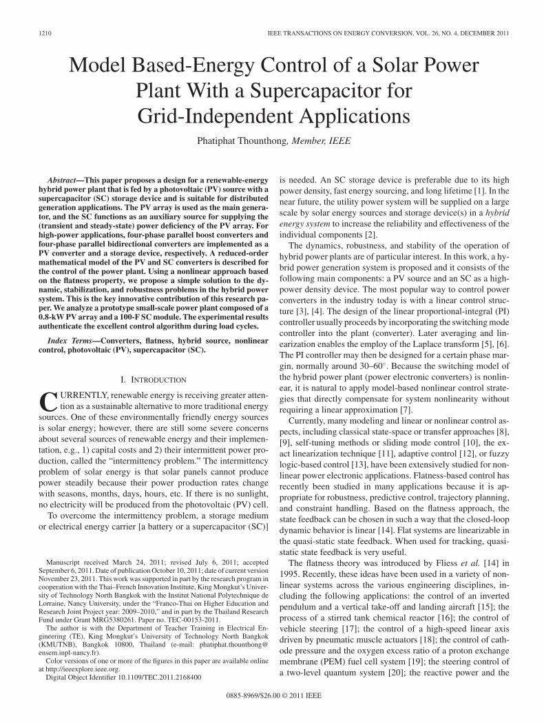
TABLE ISPECIFICATIONS OF PHOTOVOLTAIC SOURCE AND STORAGE DEVICE
TABLE IIDC-BUS ENERGY CONTROL LOOP PARAMETERS
TABLE IIISUPERCAPACITIVE ENERGY CONTROL LOOP PARAMETERS
B. Control Description
The parameters associated with the dc-bus energy regulationloop are summarized in Table II. The parameters associated withthe SC energy regulation loop are detailed in Table III. For thelow-scale test bench, the dc-bus voltage reference vBusREF (=x1REF ) was set to 60 V and the SC voltage reference vSCREF(= x2REF ) was set to 25 V (the nominal value of the SC bank).
The constant switching frequency ωS of the PV and SC con-verters was 25 kHz (157 080 rad·s−1). The nonlinear controllergains used were K11 = 450 rad·s−1 and K12 = 22 500 rad2 ·s−2
so that the system damping ratio ζ was equal to 1.5 and thenatural frequency ωn was equal to 150 rad·s−1 . As a result,the cutoff frequency ωE of the closed-loop dc-bus energy wasequal to 60 rad·s−1 . This value was lower than the cutoff fre-quency ωC of the SC power loop of 450 rad·s−1 (equivalent toa first-order delay with a time constant TC of 2.2 ms) so that thesystem was asymptotically stable [36]. The controller gain ofthe closed-loop supercapacitive energy was K21 = 0.1 W·J−1 sothat the cutoff frequency ωSC of the closed-loop supercapacitive
Fig. 8. Comparison of the dc-link stabilization of the power plant during alarge load step. (a) Exact model (rPV = 0.12 Ω, rSC = 0.10 Ω). (b) Error model(robustness) (rPV = 0.001 Ω, rSC = 0.001 Ω).
energy was equal to 0.1 rad·s−1 in which ωSC << ωE , in orderto guarantee the asymptotic stability of the whole system.
The PV and SC current regulation loops and the elec-tronic protections were realized by analog circuits. The twoenergy-control loops, which generate current references iPVREFand iSCREF , were implemented in the real-time card dSPACEDS1104 platform (see Fig. 7) using the fourth-order Runge–Kutta integration algorithm and a sampling time of 80 μs withinthe mathematical environment of MATLAB–Simulink.
C. Experimental Results
Because flatness-based control is model based, it may havesome sensitivity to error in model parameters. To authenticateits robustness, the flatness-based control was tested with theexact model parameters (rPV = 0.12 Ω and rSC = 0.10 Ω)and the erroneous parameters case (rPV = 0.001 Ω and rSC =
1216 IEEE TRANSACTIONS ON ENERGY CONVERSION, VOL. 26, NO. 4, DECEMBER 2011
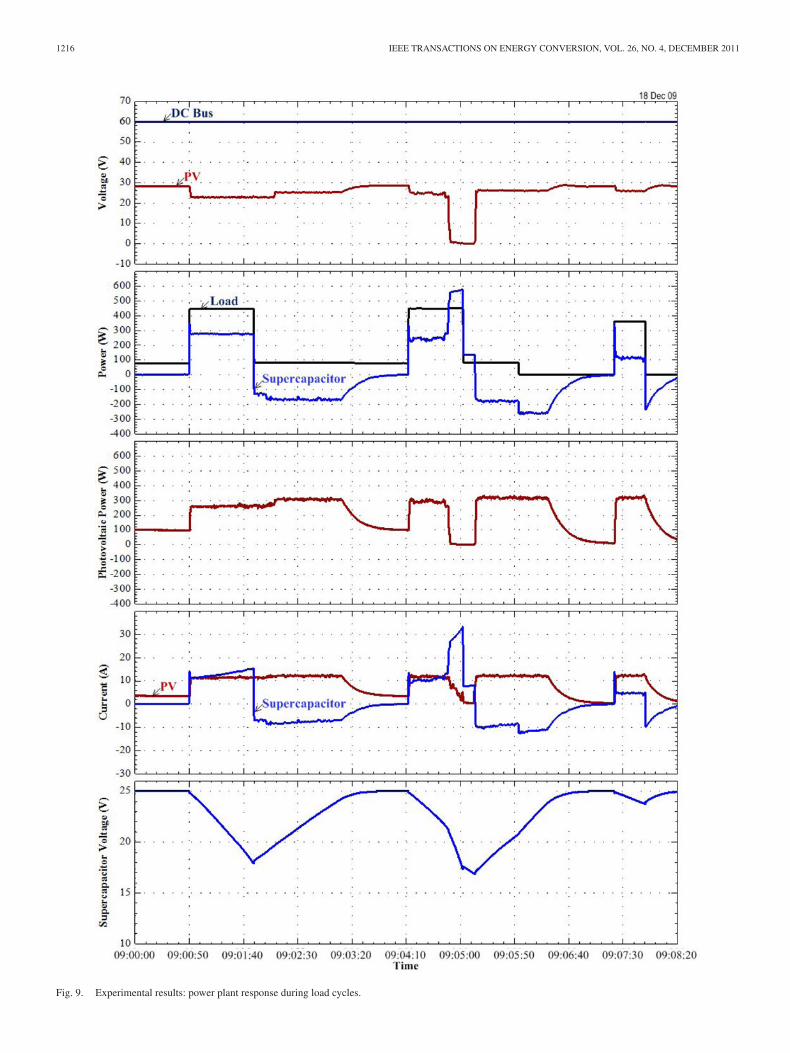
Fig. 9. Experimental results: power plant response during load cycles.

THOUNTHONG: MODEL BASED-ENERGY CONTROL OF A SOLAR POWER PLANT WITH A SUPERCAPACITOR 1217
0.001 Ω). For the sake of the dc-bus voltage stabilization and ro-bust control system, the oscilloscope waveforms in Fig. 8 showthe comparison (robustness) between the accurate parametersand the error parameters. It portrays the dynamic characteristicsthat are obtained during the large load step. It shows the dc-busvoltage, the load power (disturbance), the SC power, and theSC voltage. The initial state is in no-load power, the SC storagedevice is full of charge, i.e., the SC voltage = 25 V (vSCREF= 25 V), and the dc-bus voltage is regulated at 60 V (vBusREF= 60 V); as a result, the PV and SC powers are zero. At t =20 ms, the large load power steps from 0 W to a constant valueof 400 W (positive transition). Because during the transient statethe PV power is limited by MPPT estimation, the SC suppliesthe transient load power demand. One can scrutinize the similarwaveforms in Fig. 8(a) and (b). The dc-bus voltage (dc-link sta-bilization) is minimally influenced by the large load power step.Clearly, the performance of the control system is minimally af-fected by the model parameter error considered. Experimentaltesting demonstrates that errors in these parameters had rela-tively little effect on regulation performance, and we concludethat the nonlinear differential flatness-based approach providesa robust controller in this application.
Finally, for the sake of the dc-bus voltage stabilization andload profile (load cycles), Fig. 9 presents waveforms that are ob-tained during the load cycles measured on December 18, 2009,at an ambient temperature of around 25 ◦C. In Fig. 9, the dc-busvoltage, the PV voltage, the load power (disturbance), the SCpower, the PV power, the SC current, the PV current, and theSC voltage are shown. In the initial state, the small load poweris equal to 100 W, and the storage device is full of charge,i.e., vSC = 25 V; as a result, the SC power is zero and the PVsource supplies 100 W of power for the load. At 09:00:50,the load power steps to the final constant power of around450 W (positive load power transition). We observe the fol-lowing phenomena.
1) The SC supplies most of the transient power that is re-quired during the step load.
2) Simultaneously, the PV power increases to an MPP ofaround 250 W, which is limited by the MPPT.
3) Concurrently, the SC remains in a discharge state after theload step because the steady-state load power (approxi-mately 450 W) is greater than the power supplied by thePV array.
After that phase, one can again observe that the power plantis always energy balanced (pLoad (t) = pPV (t) + pSC (t)) bythe proposed original control algorithm. One can observe thatthe dc-bus voltage waveform is asymptotically stable during thelarge load cycles, which is of major importance when employingSC to improve the dynamic performance of the whole systemusing the proposed control law.
VI. CONCLUSION AND FURTHER WORKS
The main contribution of this paper is to model and con-trol a PV/SC hybrid power plant. The prototype power plant iscomposed of a PV array (800 W, Ekarat Solar) and an SC mod-ule (100 F, 32 V, Maxwell Technologies). A compact topology,
suitable for high-power applications, is proposed. Its workingprinciple, analysis, and design procedure are presented. The PVarray is the main source, and the SC functions as a storage device(or an auxiliary source) to compensate for the uncertainties ofthe PV source in the steady state and the transient state. An SCcan advance the load, following the characteristics of the mainsources, by providing a stronger power response to changes inthe system load. Adding energy storage to the distributed powersystems improves power quality and efficiency.
Using the nonlinear control approach based on the flatnessproperty, we propose a simple solution to the dynamic, stabiliza-tion, and robustness problems in the nonlinear power electronicsystem. And also, there are no operating points comparable witha classical linear control. This is a novel concept for this kind ofapplication. However, the proposed control law needs a load cur-rent measurement to estimate the load power. For future work,a load observer will be used to avoid a measurement of a loadcurrent, as was explored in [23].
ACKNOWLEDGMENT
The author would like to thank Dr. P. Sethakul (KMUTNB),Dr. S. Pierfederici, and Dr. B. Davat (Nancy University) for theirvaluable comments and suggestions about power electronics andcontrol.
REFERENCES
[1] Y. Cheng, “Assessments of energy capacity and energy losses of superca-pacitors in fast charging–discharging cycles,” IEEE Trans. Energy Con-vers., vol. 25, no. 1, pp. 253–261, Mar. 2010.
[2] M. Liserre, T. Sauter, and J. Y. Hung, “Future energy systems: Integratingrenewable energy sources into the smart power grid through industrialelectronics,” IEEE Ind. Electron. Mag., vol. 4, no. 1, pp. 18–37, Mar.2010.
[3] A. El Aroudi and M. Orabi, “Stabilizing technique for AC–DC boost PFCconverter based on time delay feedback,” IEEE Trans. Circuits Syst. II,Exp. Briefs, vol. 57, no. 1, pp. 56–60, Jan. 2010.
[4] Suroso and T. Noguchi, “A new three-level current-source PWM inverterand its application for grid connected power conditioner,” Energy Con-vers. Manage., vol. 51, no. 7, pp. 1491–1499, Jul. 2010.
[5] Y. A. Hajizadeh, M. A. Golkar, and A. Feliachi, “Voltage control and activepower management of hybrid fuel-cell/energy-storage power conversionsystem under unbalanced voltage sag conditions,” IEEE Trans. EnergyConvers., vol. 25, no. 4, pp. 1195–1208, Dec. 2010.
[6] L. Ming, C. K. Tse, H. H. C. Iu, M. Xikui, and M. Orabi, “Unifiedequivalent modeling for stability analysis of parallel-connected DC/DCconverters,” IEEE Trans. Circuits Syst. II, Exp. Briefs, vol. 57, no. 11,pp. 898–902, Nov. 2010.
[7] P. Thounthong, S. Pierfederici, J.-P. Martin, M. Hinaje, and B. Davat,“Modeling and control of fuel cell/supercapacitor hybrid source based ondifferential flatness control,” IEEE Trans. Veh. Technol., vol. 59, no. 6,pp. 2700–2710, Jul. 2010.
[8] N. Gyawali and Y. Ohsawa, “Integrating fuelcell/electrolyzer/ultracapacitor system into a stand-alone microhy-dro plant,” IEEE Trans. Energy Convers., vol. 25, no. 4, pp. 1092–1101,Dec. 2010.
[9] K. Acharya, S. K. Mazumder, and I. Basu, “Reaching criterion of a three-phase voltage-source inverter operating with passive and nonlinear loadsand its impact on global stability,” IEEE Trans. Ind. Electron., vol. 55,no. 4, pp. 1795–1812, Apr. 2008.
[10] X. Yu and O. Kaynak, “Sliding-mode control with soft computing: Asurvey,,” IEEE Trans. Ind. Electron., vol. 56, no. 9, pp. 3275–3285, Sep.2009.
[11] W. K. Na and B. Gou, “Feedback-linearization-based nonlinear control forPEM fuel cells,” IEEE Trans. Energy Convers., vol. 23, no. 1, pp. 179–190, Mar. 2008.

1218 IEEE TRANSACTIONS ON ENERGY CONVERSION, VOL. 26, NO. 4, DECEMBER 2011
[12] F. Jadot, F. Malrait, J. Moreno-Valenzuela, and R. Sepulchre, “Adaptiveregulation of vector-controlled induction motors,” IEEE Trans. ControlSyst. Technol., vol. 17, no. 3, pp. 646–657, May 2009.
[13] C.-S. Chiu, “T-S fuzzy maximum power point tracking control of solarpower generation systems,” IEEE Trans. Energy Convers., vol. 25, no. 4,pp. 1123–1132, Dec. 2010.
[14] M. Fliess, J. Levine, Ph. Martin, and P. Rouchon, “Flatness and defectof nonlinear systems: Introductory theory and examples,” Int. J. Contr.,vol. 61, no. 6, pp. 1327–1361, 1995.
[15] M. Fliess, J. Levine, Ph. Martin, and P. Rouchon, “A Lie–Backlund ap-proach to equivalence and flatness of nonlinear systems,” IEEE Trans.Automat. Contr., vol. 44, no. 5, pp. 922–937, May 1999.
[16] M. Guay, “On the linearizability of nonisothermal continuous stirred-tankreactors,” Automatica, vol. 38, no. 2, pp. 269–278, Feb. 2002.
[17] J. Villagra, B. A. Novel, H. Mounier, and M. Pengov, “Flatness-basedvehicle steering control strategy with SDRE feedback gains tuned via asensitivity approach,” IEEE Trans. Control Syst. Technol., vol. 15, no. 3,pp. 554–564, May 2007.
[18] H. Aschemann and D. Schindele, “Sliding-mode control of a high-speedlinear axis driven by pneumatic muscle actuators,,” IEEE Trans. Ind.Electron., vol. 55, no. 1, pp. 3855–3864, Nov. 2008.
[19] M. A. Danzer, J. Wilhelm, H. Aschemann, and E. P. Hofer, “Model-basedcontrol of cathode pressure and oxygen excess ratio of a PEM fuel cellsystem,” J. Power Sources, vol. 176, no. 2, pp. 515–522, Feb. 2008.
[20] P. S. P. da Silva and P. Rouchon, “Flatness-based control of a single qubitgate,,” IEEE Trans. Automat. Contr., vol. 53, no. 3, pp. 775–779, Apr.2008.
[21] E. Song, A. F. Lynch, and V. Dinavahi, “Experimental validation of non-linear control for a voltage source converter,” IEEE Trans. Control Syst.Technol., vol. 17, no. 5, pp. 1135–1144, Sep. 2009.
[22] T. Rabbani, S. Munier, D. Dorchies, P. Malaterre, A. Bayen, and X. Litrico,“Flatness-based control of open-channel flow in an irrigation canal usingSCADA,” IEEE Control Syst. Mag., vol. 29, no. 5, pp. 22–30, Oct. 2009.
[23] A. Gensior, H. Sira-Ramirez, J. Rudolph, and H. Guldner, “On some non-linear current controllers for three-phase boost rectifiers,,” IEEE Trans.Ind. Electron., vol. 56, no. 2, pp. 360–370, Feb. 2009.
[24] L. R. Chen, C. H. Tsai, Y. L. Lin, and Y. S. Lai, “A biological swarmchasing algorithm for tracking the PV maximum power point,” IEEETrans. Energy Convers., vol. 25, no. 2, pp. 484–493, Jun. 2010.
[25] T. L. Gibson and N. A. Kelly, “Solar photovoltaic charging of lithium-ionbatteries,” J. Power Sources, vol. 195, no. 12, pp. 3928–3932, Jun. 2010.
[26] O. Lopez, F. D. Freijedo, A. G. Yepes, P. F. Comesana, J. Malvar,R. Teodorescu, and J. Doval-Gandoy, “Eliminating ground current in atransformerless photovoltaic application,” IEEE Trans. Energy Convers.,vol. 25, no. 1, pp. 140–147, Mar. 2010.
[27] A. Khaligh and Z. Li, “Battery, ultracapacitor, fuel cell, and hybrid energystorage systems for electric, hybrid electric, fuel cell, and plug-in hybridelectric vehicles: state of the art,” IEEE Trans. Veh. Technol., vol. 59,no. 6, pp. 2806–2814, Jul. 2010.
[28] J. R. Mille, “Introduction to electrochemical capacitor technology,” IEEEElectr. Insulat. Mag. Mille, vol. 26, no. 4, pp. 40–47, Jul. 2010.
[29] V. Agarwal, K. Uthaichana, R. A. DeCarlo, and L. H. Tsoukalas, “De-velopment and validation of a battery model useful for discharging andcharging power control and lifetime estimation,” IEEE Trans. EnergyConvers., vol. 25, no. 1, pp. 140–147, Mar. 2010.
[30] M. Inagaki, H. Konno, and O. Tanaike, “Carbon materials for electro-chemical capacitors,” J. Power Sources, vol. 195, no. 24, pp. 7880–7903,Dec. 2010.
[31] A. Hammar, P. Venet, R. Lallemand, G. Coquery, and G. Rojat, “Studyof accelerated aging of supercapacitors for transport applications,” IEEETrans. Ind. Electron., vol. 57, no. 12, pp. 3972–3979, Dec. 2010.
[32] P. Thounthong, S. Rael, and B. Davat, “Analysis of supercapacitor assecond source based on fuel cell power generation,” IEEE Trans. EnergyConvers., vol. 24, no. 1, pp. 247–255, Mar. 2009.
[33] G. Spagnuolo, G. Petrone, S. V. Araujo, C. Cecati, E. Friis-Madsen, E. Gu-bia, D. Hissel, M. Jasinski, W. Knapp, M. Liserre, P. Rodriguez, R. Teodor-escu, and P. Zacharias, “Renewable energy operation and conversionschemes: A summary of discussions during the seminar on renewable en-ergy systems,” in IEEE Ind. Electron. Mag., no. 1. vol. 4, Mar. 2010,pp. 38–51.
[34] P. Thounthong and B. Davat, “Study of a multiphase interleaved step-up converter for fuel cell high power applications,,” Energy Convers.Manage., vol. 51, no. 4, pp. 826–832, Apr. 2010.
[35] S. D. Sudhoff, K. A. Corzine, S. F. Glover, H. J. Hegner, and H. N. Robey,Jr., “DC link stabilized field oriented control of electric propulsion sys-tems,” IEEE Trans. Energy Convers, vol. 13, no. 1, pp. 27–33, Mar.1998.
[36] P. Thounthong, S. Pierfederici, and B. Davat, “Analysis of differentialflatness-based control for a fuel cell hybrid power source,” IEEE Trans.Energy Convers., vol. 25, no. 3, pp. 909–920, Sep. 2010.
[37] P. Thounthong and S. Pierfederici, “A new control law based on the dif-ferential flatness principle for multiphase interleaved DC–DC converter,”IEEE Trans. Circuits Syst. II, Exp. Briefs, vol. 57, no. 11, pp. 903–907,Nov. 2010.
Phatiphat Thounthong (M’09) received the B.S.and M.E. degrees in electrical engineering from KingMongkut’s Institute of Technology North Bangkok(KMITNB), Bangkok, Thailand, in 1996 and 2001,respectively, and the Ph.D. degree in electrical engi-neering from the Institut National Polytechnique deLorraine (INPL)-Nancy University, Nancy-Lorraine,France, in 2005.
He is currently an Associate Professor in the De-partment of Teacher Training in Electrical Engineer-ing (TE), King Mongkut’s University of Technology
North Bangkok (KMUTNB). His current research interests include power elec-tronics, electric drives, and electrical devices (fuel cell, solar cell, wind turbine,batteries, and SC).