Embed Size (px)
Citation preview
1210 - 1
SECTION 1210 – PAVEMENT MARKING 1210-1 DESCRIPTION This work consists of furnishing and installing specified pavement markings at the designated locations. 1210-2 MATERIALS 1210-2.1 PAVEMENT MARKING PAINT A. General.
1. Quality. All paint shall be formulated from first grade materials and shall be suitable in all respects for application at elevated spray temperatures with drop-on glass beads using conventional traffic striping equipment. The finished paint shall be smooth and homogeneous, free of coarse particles, skins, or any other foreign materials that are detrimental to its use or appearance.
2. Manufacturing and Packaging of Preapproved Paint. When preapproval
of pavement marking paint is specified, the paint shall be manufactured in lot sizes no smaller than 1,000 gallons. The paint shall be screened with a 40 mesh or finer screen to remove any coarse particles, skins, or foreign materials. Paint shall be packaged in 55 gallon drums coated with a non-corrosive lining. The outside coating of drums shall be a pastel color. The storage temperature shall be kept at 32°F or higher.
3. Package Stability of Preapproved Paint. Within a period of 12 months from the
time of delivery, the paint shall not cake, settle, liver, thicken, skin, curdle, gel, or show any other objectionable properties which cannot readily be corrected with minimal stirring. Any paint with properties that make it unsuitable for use within the specified 12 months shall be rejected and replaced with paint that meets the specifications. All costs incurred in replacing the paint shall be at the CONTRACTOR’s expense.
B. Specific Requirements for Solvent-Based Traffic Marking Paint. Solvent-
based pavement marking paint shall meet the general requirements of AASHTO M248-86: “Ready Mixed White and Yellow Traffic Paints” except for the following requirements:
AASHTO M248-86, Section 4.1.2, shall be revised as follows:
ASTM D476 Type I Anatase, or Type II Rutile shall be used.
AASHTO M248-86, Section 5.2.1, Extracted Pigment Requirements, shall be revised as follows:
1210 - 2
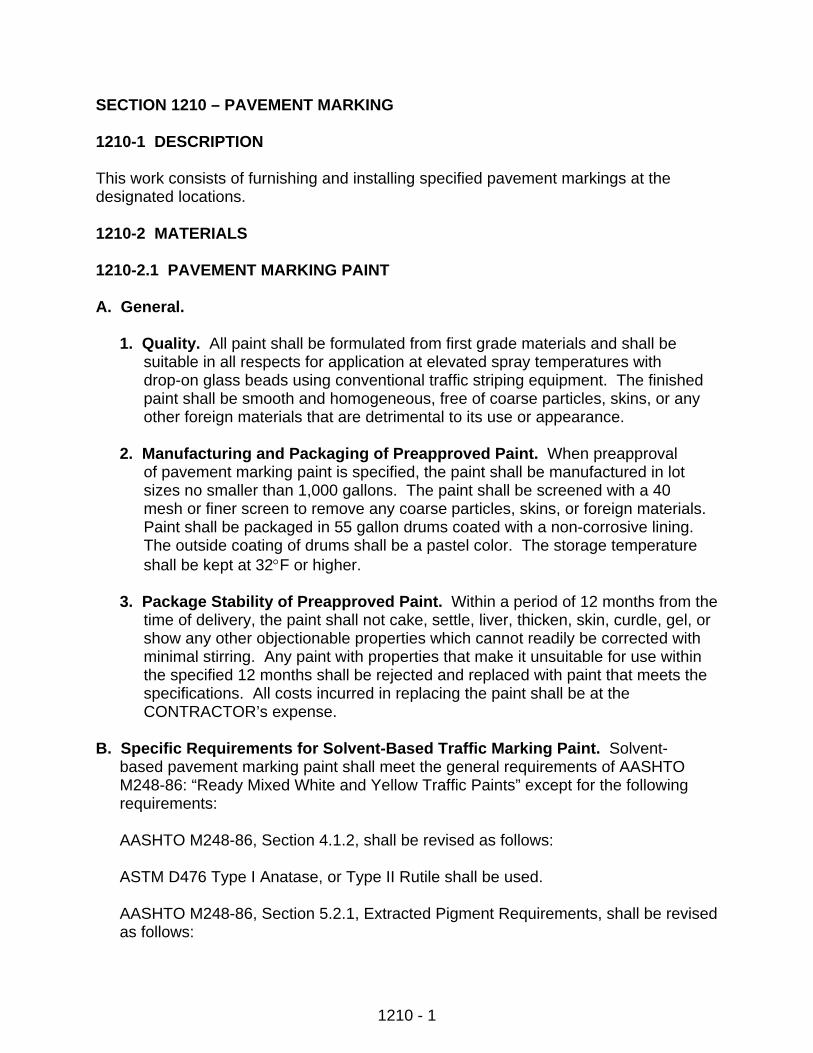
The minimum purity requirements for the respective materials shall be as given in Sections 4.1.1 through 4.1.5.
Composition of Solvent-Based Paint
White Traffic Paint
Pigment Ingredients Type S Type F (% of Pigment) Titanium Dioxide, Min. (Pure) 18.9 17.5 Calcium Carbonate 26.0-30.0 35.0-40.0 Magnesium Silicate 51.0-55.0 35.0-43.0 Zinc Oxide, Min. — 3.0
Composition of Solvent Based Paint
Yellow Traffic Paint
Pigment Ingredients Type S Type F (% of Pigment) Lead Chromate, Min. (Pure) 18.3 16.7 Calcium Carbonate 24.5-29.5 35.0-40.0 Magnesium Silicate 52.0-57.0 35.0-43.0
AASHTO M248-86, Section 5.3, shall be revised as follows:
Composition of Non-Volatile Vehicle
White and Yellow Traffic Paint
Hypalon* Vehicle Ingredients Chlorinated Acrylic Chlorinated (% by Wt. of Vehicle) Polyolefin Copolymer Rubber
Type S Type F Type F Type F
Alkyd Resin Solids (±0.5%) 100 41.14 41.14 37.6 Acrylic Copolymer BR-201 (±0.5%) — — 47.25 — Chlorinated Rubber (±0.5%) — — — 37.0 Chlorinated Paraffin (±0.5%) — 11.61 11.61 25.4 Chlorinated Polyolefin, (CP-173) (±0.5%) — 47.25 — —
*Solvent is 100% MEK except for Alkyd Resin solution.
AASHTO M248-86, Section 5.4, shall be revised as follows:
1210 - 3
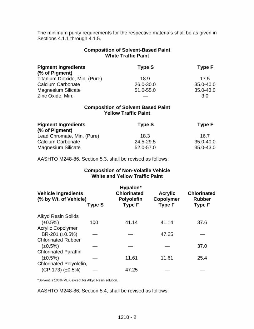
Quantitative Requirements of White Solvent-Based Paint
Characteristics Type S Type F Titanium Dioxide (as % of Extr. Pigment) (min) (Pure) 18.9 17.5 Pigment (%) 49.0 –51.0 49.0 –51.0 Total Solids (%) (min) 68.5 69.0 Vehicle Solids (%) (min) 37.0 38.0 Weight per Gallon (lbs) (min) 10.6 11.1 Viscosity (K.U.) 70-80 70-85 Fineness of Grind (Hegman) (min) 2.0 2.0 Drying Time (Minutes) (max) 20.0 10.0 Directional Reflectance, (%) (min) 80 80 Uncombined Water (%) (max) 1.0 1.0 Particles and Skins Retained on 325 Mesh Sieve (%) (max) 1.0 1.0
Quantitative Requirements of Yellow Paint
Characteristics Type S Type F Lead Chromate (as % of Extr. Pigment) (min) (Pure) 18.3 16.7 Pigment (%) 50.0-52.0 50.0-52.0 Total Solids (%) (min) 69.2 69.5 Vehicle Solids (%) (min) 37.0 38.0 Weight per Gallon (lbs) (min) 10.8 11.3 Viscosity (K.U.) 70-80 70-85 Fineness of Grind (Hegman) (min) 2.0 2.0 Drying Time (Minutes) (max) 20.0 10.0 Color (to pass Fed. Std.) (Chip #33538) Directional Reflectance, (%) (min) 50 50 Uncombined Water (%) (max) 1.0 1.0 Particles and Skins Retained on 325 Mesh Sieve (%) (max) 1.0 1.0
C. Specific Requirements for Water-Based Traffic Marking Paint. The exact
composition of the water-based traffic paint shall be left to the manufacturer, provided the finished paint meets the following:
1210 - 4
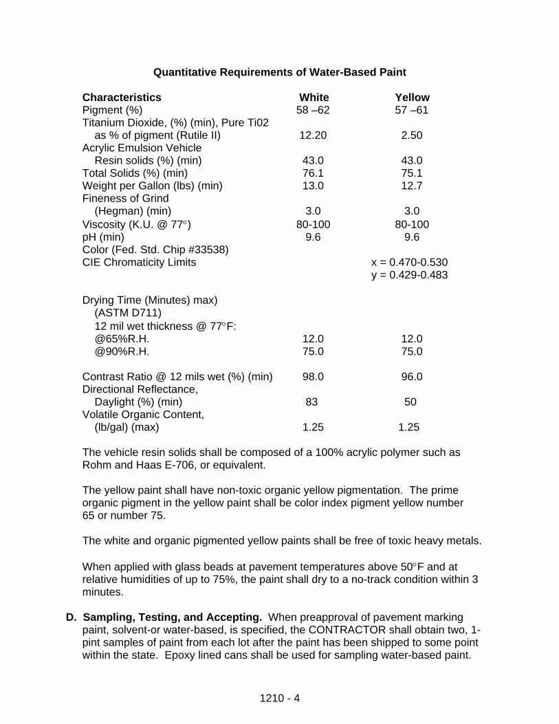
Quantitative Requirements of Water-Based Paint
Characteristics White Yellow Pigment (%) 58 –62 57 –61 Titanium Dioxide, (%) (min), Pure Ti02 as % of pigment (Rutile II) 12.20 2.50 Acrylic Emulsion Vehicle Resin solids (%) (min) 43.0 43.0 Total Solids (%) (min) 76.1 75.1 Weight per Gallon (lbs) (min) 13.0 12.7 Fineness of Grind (Hegman) (min) 3.0 3.0 Viscosity (K.U. @ 77°) 80-100 80-100 pH (min) 9.6 9.6 Color (Fed. Std. Chip #33538) CIE Chromaticity Limits x = 0.470-0.530
y = 0.429-0.483
Drying Time (Minutes) max) (ASTM D711) 12 mil wet thickness @ 77°F: @65%R.H. 12.0 12.0 @90%R.H. 75.0 75.0
Contrast Ratio @ 12 mils wet (%) (min) 98.0 96.0 Directional Reflectance, Daylight (%) (min) 83 50 Volatile Organic Content, (lb/gal) (max) 1.25 1.25
The vehicle resin solids shall be composed of a 100% acrylic polymer such as Rohm and Haas E-706, or equivalent.
The yellow paint shall have non-toxic organic yellow pigmentation. The prime organic pigment in the yellow paint shall be color index pigment yellow number 65 or number 75.
The white and organic pigmented yellow paints shall be free of toxic heavy metals.
When applied with glass beads at pavement temperatures above 50°F and at relative humidities of up to 75%, the paint shall dry to a no-track condition within 3 minutes.
D. Sampling, Testing, and Accepting. When preapproval of pavement marking
paint, solvent-or water-based, is specified, the CONTRACTOR shall obtain two, 1- pint samples of paint from each lot after the paint has been shipped to some point within the state. Epoxy lined cans shall be used for sampling water-based paint.
1210 - 5
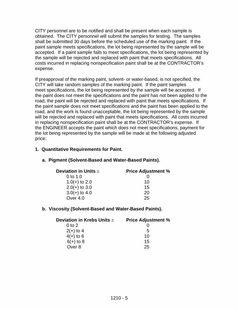
CITY personnel are to be notified and shall be present when each sample is obtained. The CITY personnel will submit the samples for testing. The samples shall be submitted 30 days before the scheduled use of the marking paint. If the paint sample meets specifications, the lot being represented by the sample will be accepted. If a paint sample fails to meet specifications, the lot being represented by the sample will be rejected and replaced with paint that meets specifications. All costs incurred in replacing nonspecification paint shall be at the CONTRACTOR’s expense.
If preapproval of the marking paint, solvent- or water-based, is not specified, the CITY will take random samples of the marking paint. If the paint samples meet specifications, the lot being represented by the sample will be accepted. If the paint does not meet the specifications and the paint has not been applied to the road, the paint will be rejected and replaced with paint that meets specifications. If the paint sample does not meet specifications and the paint has been applied to the road, and the work is found unacceptable, the lot being represented by the sample will be rejected and replaced with paint that meets specifications. All costs incurred in replacing nonspecification paint shall be at the CONTRACTOR’s expense. If the ENGINEER accepts the paint which does not meet specifications, payment for the lot being represented by the sample will be made at the following adjusted price:
1. Quantitative Requirements for Paint.
a. Pigment (Solvent-Based and Water-Based Paints).
Deviation in Units ± Price Adjustment % 0 to 1.0 0 1.0(+) to 2.0 10 2.0(+) to 3.0 15 3.0(+) to 4.0 20 Over 4.0 25
b. Viscosity (Solvent-Based and Water-Based Paints).
Deviation in Krebs Units ± Price Adjustment %
0 to 2 0 2(+) to 4 5
4(+) to 6 10 6(+) to 8 15 Over 8 25
1210 - 6
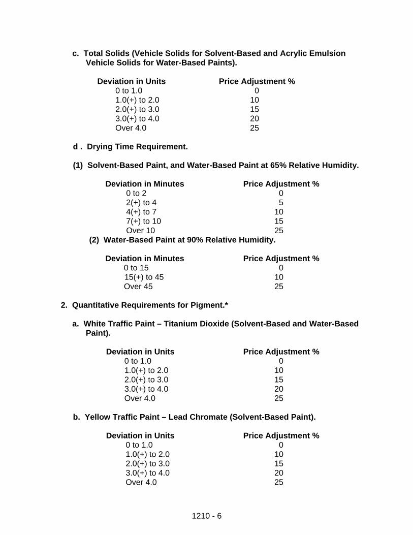
c. Total Solids (Vehicle Solids for Solvent-Based and Acrylic Emulsion Vehicle Solids for Water-Based Paints).
Deviation in Units Price Adjustment % 0 to 1.0 0 1.0(+) to 2.0 10 2.0(+) to 3.0 15 3.0(+) to 4.0 20 Over 4.0 25
d . Drying Time Requirement.
(1) Solvent-Based Paint, and Water-Based Paint at 65% Relative Humidity.
Deviation in Minutes Price Adjustment %
0 to 2 0 2(+) to 4 5 4(+) to 7 10 7(+) to 10 15 Over 10 25
(2) Water-Based Paint at 90% Relative Humidity.
Deviation in Minutes Price Adjustment % 0 to 15 0
15(+) to 45 10 Over 45 25
2. Quantitative Requirements for Pigment.*
a. White Traffic Paint – Titanium Dioxide (Solvent-Based and Water-Based
Paint).
Deviation in Units Price Adjustment % 0 to 1.0 0 1.0(+) to 2.0 10 2.0(+) to 3.0 15 3.0(+) to 4.0 20 Over 4.0 25
b. Yellow Traffic Paint – Lead Chromate (Solvent-Based Paint).
Deviation in Units Price Adjustment %
0 to 1.0 0 1.0(+) to 2.0 10 2.0(+) to 3.0 15 3.0(+) to 4.0 20 Over 4.0 25
1210 - 7
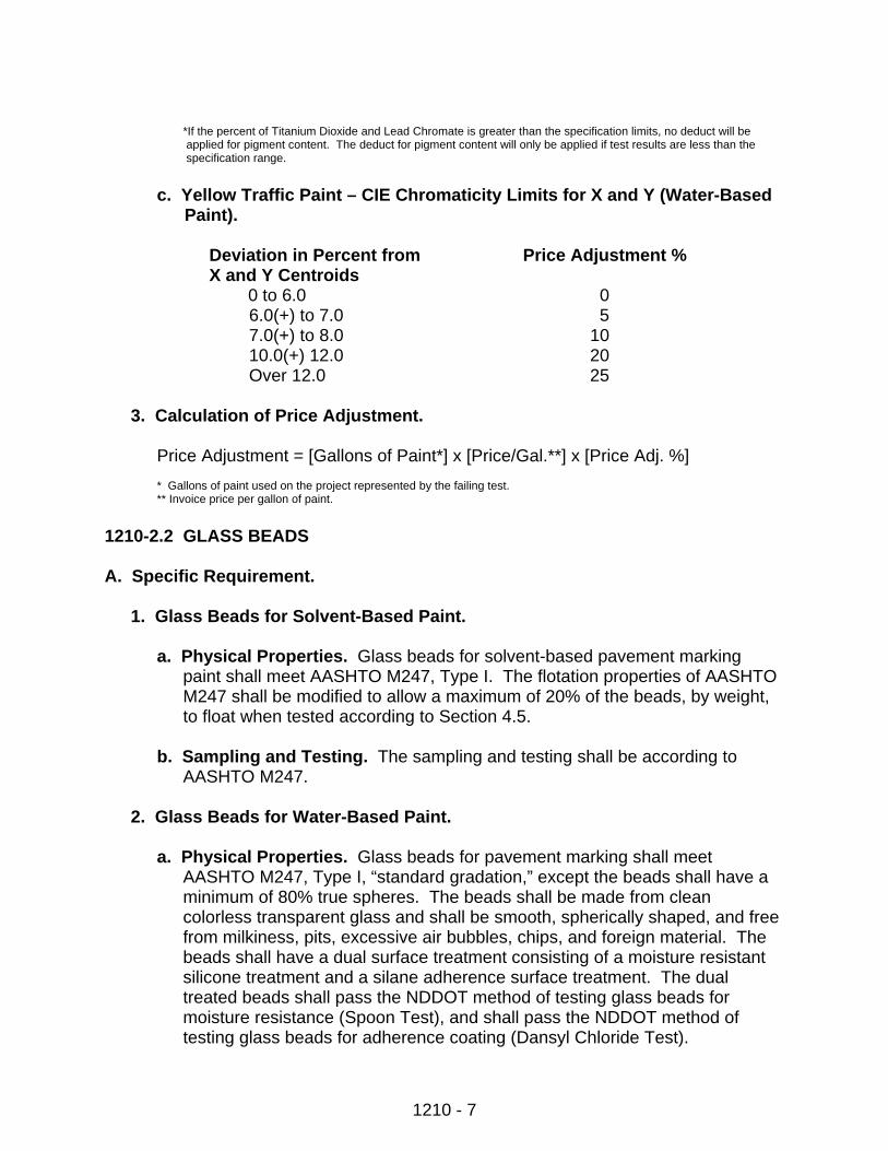
*If the percent of Titanium Dioxide and Lead Chromate is greater than the specification limits, no deduct will be applied for pigment content. The deduct for pigment content will only be applied if test results are less than the specification range.
c. Yellow Traffic Paint – CIE Chromaticity Limits for X and Y (Water-Based
Paint).
Deviation in Percent from Price Adjustment % X and Y Centroids 0 to 6.0 0
6.0(+) to 7.0 5 7.0(+) to 8.0 10
10.0(+) 12.0 20 Over 12.0 25
3. Calculation of Price Adjustment.
Price Adjustment = [Gallons of Paint*] x [Price/Gal.**] x [Price Adj. %]
* Gallons of paint used on the project represented by the failing test. ** Invoice price per gallon of paint.
1210-2.2 GLASS BEADS A. Specific Requirement.
1. Glass Beads for Solvent-Based Paint.
a. Physical Properties. Glass beads for solvent-based pavement marking paint shall meet AASHTO M247, Type I. The flotation properties of AASHTO M247 shall be modified to allow a maximum of 20% of the beads, by weight, to float when tested according to Section 4.5.
b. Sampling and Testing. The sampling and testing shall be according to
AASHTO M247.
2. Glass Beads for Water-Based Paint.
a. Physical Properties. Glass beads for pavement marking shall meet AASHTO M247, Type I, “standard gradation,” except the beads shall have a minimum of 80% true spheres. The beads shall be made from clean colorless transparent glass and shall be smooth, spherically shaped, and free from milkiness, pits, excessive air bubbles, chips, and foreign material. The beads shall have a dual surface treatment consisting of a moisture resistant silicone treatment and a silane adherence surface treatment. The dual treated beads shall pass the NDDOT method of testing glass beads for moisture resistance (Spoon Test), and shall pass the NDDOT method of testing glass beads for adherence coating (Dansyl Chloride Test).

1210 - 8
b. Sampling and Testing. The sampling and testing shall be according to the
NDDOT’s sampling and testing methods. B. Packaging and Marking. The beads shall be furnished in moisture-proof
containers or moisture-proof bags. Each container or bag shall be marked with name of contents, manufacturer, net weight, lot number, and ton number.
C. Certification. The manufacturer shall furnish one copy of a certificate for each lot
of the material furnished, giving the properties of the beads and certifying that they meet the required specifications. The affidavit shall show designation of the sample, lot number, and date of manufacture.
1210-2.3 PLASTIC PAVEMENT MARKING FILM (RETROREFLECTIVE) A. General. The prefabricated plastic pavement markings shall consist of white or
yellow pigmented plastic films, conforming to standard highway colors, with reflective glass spheres incorporated throughout the entire cross-sectional area and a layer of reflective glass spheres bonded to the top surface. The pavement markings shall adhere to bituminous or Portland Cement Concrete pavements by either a pressure-sensitive precoated adhesive or a liquid contact cement. The markings shall be provided in a form that facilitates rapid application and protects the markings in shipment and storage. The manufacturer shall identify proper solvents and adhesives to be applied at the time of application, all equipment necessary for proper application, and recommendations for application that assures an effective performance life. The marking material shall mold itself to pavement contours by the action of traffic. The pavement marking films shall also be capable of application on new bituminous concrete wearing courses during the paving operation according to the manufacturer’s instructions. After application, the markings shall be immediately ready for traffic.
Prefabricated legend and symbols shall meet the applicable shapes and sizes shown in the Contract.
B. Retroreflective Pliant Polymer. The pavement marking film shall consist of a
mixture of high quality polymeric material, pigments,1.5 index glass beads uniformly distributed throughout its cross-sectional area, and a reflective layer of beads bonded to the top surface. These materials shall be as follows:
Materials Minimum Percent by Weight Resins & Plasticizers 20 Pigments 30 Graded Glass Beads 33
The remaining 17% shall be comprised of the above materials in various proportions.
1210 - 9
These materials shall be fabricated into pavement marking film of specified thickness and dimensions.
C. Requirements.
1. Skid Resistance. The surface of the marking film shall provide a minimum skid resistance value of 45 BPN when tested according to ASTM E303.
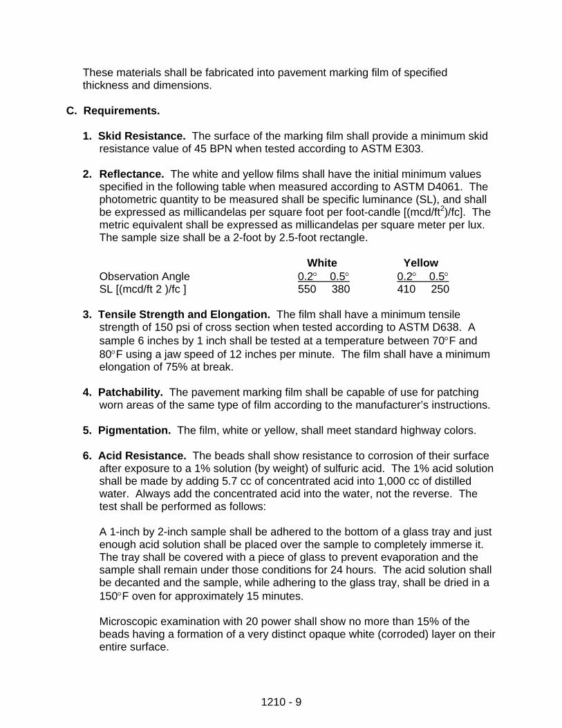
2. Reflectance. The white and yellow films shall have the initial minimum values
specified in the following table when measured according to ASTM D4061. The photometric quantity to be measured shall be specific luminance (SL), and shall be expressed as millicandelas per square foot per foot-candle [(mcd/ft2)/fc]. The metric equivalent shall be expressed as millicandelas per square meter per lux. The sample size shall be a 2-foot by 2.5-foot rectangle.
White Yellow
Observation Angle 0.2° 0.5° 0.2° 0.5° SL [(mcd/ft 2 )/fc ] 550 380 410 250
3. Tensile Strength and Elongation. The film shall have a minimum tensile
strength of 150 psi of cross section when tested according to ASTM D638. A sample 6 inches by 1 inch shall be tested at a temperature between 70°F and 80°F using a jaw speed of 12 inches per minute. The film shall have a minimum elongation of 75% at break.
4. Patchability. The pavement marking film shall be capable of use for patching
worn areas of the same type of film according to the manufacturer’s instructions.
5. Pigmentation. The film, white or yellow, shall meet standard highway colors.
6. Acid Resistance. The beads shall show resistance to corrosion of their surface after exposure to a 1% solution (by weight) of sulfuric acid. The 1% acid solution shall be made by adding 5.7 cc of concentrated acid into 1,000 cc of distilled water. Always add the concentrated acid into the water, not the reverse. The test shall be performed as follows:
A 1-inch by 2-inch sample shall be adhered to the bottom of a glass tray and just enough acid solution shall be placed over the sample to completely immerse it. The tray shall be covered with a piece of glass to prevent evaporation and the sample shall remain under those conditions for 24 hours. The acid solution shall be decanted and the sample, while adhering to the glass tray, shall be dried in a 150°F oven for approximately 15 minutes.
Microscopic examination with 20 power shall show no more than 15% of the beads having a formation of a very distinct opaque white (corroded) layer on their entire surface.
1210 - 10
7. Reflective Retention. To have effective performance life, the glass beads shall be strongly bonded. One of the following tests shall be employed to measure reflective retention:
a. Taber Abrader Simulation Test. Using a taber abrader with an H-18 wheel
and a 125 gram load, the sample shall be inspected at 200 cycles under a microscope and no more than 15% of the beads shall be lost due to popouts.
b. Qualitative Tests. Bead bond strengths shall be judged under a microscope
with a magnification of at least 5-power. The beads shall be difficult to remove and bead removal shall remove a portion of the polymeric bead bond with the bead rather than popping out clean from their sockets.
8. Thickness. The film, without adhesive, shall be supplied in a standard thickness
of 0.06 inch.
9. Effective Performance Life. The film, when applied according to the manufacturer, shall provide a neat, durable marking that will not flow or distort due to temperature. Although reflectivity is reduced by wear, the film shall provide a cushioned resilient substrate that reduces bead crushing and loss. The film shall be weather resistant and through normal traffic wear, shall not fade, lift, or shrink throughout the life of the marking and shall show no significant tearing, roll back, or other signs of poor adhesion.
1210-2.4 DURABLE PREFORMED PAVEMENT MARKINGS A. General. The pavement marking material shall consist of white or yellow
Retroreflective pliant polymer materials designed for longitudinal and word/symbol markings subjected to high traffic volumes and severe wear conditions meeting the following:
The markings shall be manufactured and packaged to permit storage at manufacturer’s recommended shelf temperature for a period of not less than one year from the date of purchase.
Prefabricated legends and symbols shall meet the shapes and sizes as shown on the Standard Drawings.
The CONTRACTOR shall secure from the manufacturer all warranties and guarantees with respect to materials, parts, workmanship, or performance which the products covered by the proposal bear, and include these warranties and guarantees with the certification.
B. Composition. Durable preformed pavement markings shall consist of a mixture
of high-quality polymeric materials, pigments, and glass beads distributed throughout its base cross-sectional area, with a reflective layer of beads embedded into the patterned surface.
1210 - 11
The preformed markings shall adhere to asphalt concrete or Portland Cement concrete by a precoated pressure sensitive adhesive. A primer may be used to precondition the pavement surface. The preformed markings shall conform to pavement contours by the action of traffic. The pavement markings shall be capable of application on new, dense, and open graded asphalt concrete wearing courses during the paving operation according to the manufacturer’s instructions. After application, the markings shall be immediately ready for traffic.
C. Skid Resistance. The surface of the durable preformed markings shall provide an
initial minimum skid resistance value of 45 BPN when tested according to ASTM E303.
D. Thickness. The material without adhesive shall have a minimum caliper of 0.06
inch at the thickest portion of the cross section and a minimum caliper of 0.02 inch at the thinnest portion of the cross section.
E. Beads.
1. Index of Refraction. The glass beads on the surface of the material shall have a minimum index of refraction of 1.70 when tested using the liquid oil immersion method. The glass beads mixed into the pliant polymer shall have a minimum index of refraction of 1.5 when tested by the oil immersion method. The size and quality of the beads shall be such that the performance requirements for the durable preformed markings shall be met.
2. Bead Adhesion. Adhesion shall be such that beads are not easily removed
when the film surface is scratched firmly with a thumbnail.
3. Acid Resistance. The beads shall show resistance to corrosion of their surface after exposure to a 1% solution (by weight) of sulfuric acid. The 1% acid solution shall be made by adding 5.7 cc of concentrated acid into 1,000 cc of distilled water. Always add the concentrated acid into the water, not the reverse. The test shall be performed as follows:
A 1-inch by 2-inch sample shall be adhered to the bottom of a glass tray and just enough acid solution shall be placed over the sample to completely immerse it. The tray shall be covered with a piece of glass to prevent evaporation and the sample shall remain under those conditions for 24 hours. The acid solution shall be decanted and the sample, while adhering to the glass tray, shall be dried in a 150°F oven for approximately 15 minutes.
Microscopic examination with 20 power shall show no more than 15% of the beads having a formation of a very distinct opaque white (corroded) layer on their entire surface.
1210 - 12
F. Patchability. The pavement marking material shall be capable of use for patching worn areas of the same type according to manufacturer’s instructions.
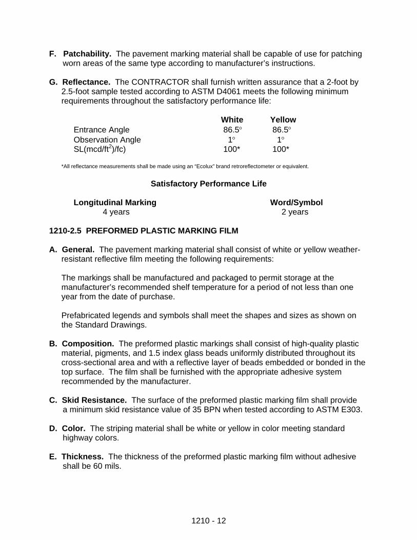
G. Reflectance. The CONTRACTOR shall furnish written assurance that a 2-foot by
2.5-foot sample tested according to ASTM D4061 meets the following minimum requirements throughout the satisfactory performance life:
White Yellow
Entrance Angle 86.5° 86.5° Observation Angle 1° 1° SL(mcd/ft2)/fc) 100* 100*
*All reflectance measurements shall be made using an “Ecolux” brand retroreflectometer or equivalent.
Satisfactory Performance Life
Longitudinal Marking Word/Symbol
4 years 2 years 1210-2.5 PREFORMED PLASTIC MARKING FILM A. General. The pavement marking material shall consist of white or yellow weather-
resistant reflective film meeting the following requirements:
The markings shall be manufactured and packaged to permit storage at the manufacturer’s recommended shelf temperature for a period of not less than one year from the date of purchase.
Prefabricated legends and symbols shall meet the shapes and sizes as shown on the Standard Drawings.
B. Composition. The preformed plastic markings shall consist of high-quality plastic
material, pigments, and 1.5 index glass beads uniformly distributed throughout its cross-sectional area and with a reflective layer of beads embedded or bonded in the top surface. The film shall be furnished with the appropriate adhesive system recommended by the manufacturer.
C. Skid Resistance. The surface of the preformed plastic marking film shall provide
a minimum skid resistance value of 35 BPN when tested according to ASTM E303. D. Color. The striping material shall be white or yellow in color meeting standard
highway colors. E. Thickness. The thickness of the preformed plastic marking film without adhesive
shall be 60 mils.
1210 - 13
F. Durability and Wear Resistance. The preformed plastic marking film, when properly applied, shall provide a neat, durable marking. The preformed plastic marking film shall provide a cushioned resilient surface substrate that reduces bead crush and loss. The film shall be weather resistant and through normal traffic wear shall not fade, lift, or shrink throughout the life of the marking, and show no significant tearing, roll back, or other signs of poor adhesion.
G. Tensile Strength. The film shall have a minimum tensile strength of 40 psi of
cross section when tested according to ASTM D638. H. Conformability and Resealing. The preformed film shall conform to pavement
contours, breaks, faults, etc., through the action of traffic at normal pavement temperatures. The film shall have resealing characteristics that will fuse with itself and previously-applied marking film of the same composition under normal conditions of use.
I. Elongation. The film shall have a maximum elongation of 100% when tested
according to ASTM D638. J. Plastic Pull Test. A test specimen 1 inch by 3 inches shall support a dead
weight of 5 pounds for not less than 5 minutes at a temperature between 70° and 80°F.
1210-2.6 PREFORMED PATTERNED PAVEMENT MARKING FILM A. General. The preformed patterned markings shall consist of white or yellow films
with ceramic beads incorporated to provide immediate and continuing retroreflection and shall meet the following requirements:
The markings shall be manufactured and packaged to permit storage at manufacturer’s recommended shelf temperature for a period of not less than one year from the date of purchase.
Legends and symbols shall confirm to the shapes and sizes as shown on the NDDOT Standard Drawings.
The CONTRACTOR shall secure from the manufacturer all warranties and guarantees with respect to materials, workmanship, or performance which the products covered by the proposal bear, and include these warranties and guarantees with the certification.
B. Composition. The retroreflective pliant polymer pavement markings shall consist of
a mixture of high-quality polymeric materials, pigments, and glass beads distributed throughout its base cross-sectional area, with a reflective layer of ceramic beads bonded to a durable polyurethane topcoat surface. The patterned surface shall have approximately 50% + or - 15% of the surface area raised and presenting a near
1210 - 14
vertical face to traffic from any direction. The channels between the raised areas shall be substantially free of exposed beads or particles.
The preformed markings shall conform to pavement contours by the action of traffic. The pavement markings shall be capable of application on new, dense, and open graded asphalt wearing courses during the paving operation according to the manufacturer’s instructions. After application, the marking shall be immediately ready for traffic.
C. Skid Resistance. The surface of the tape shall provide an initial minimum skid
resistance value of 45 BPN when tested according to ASTM E303 except values shall be taken at downweb and at a 45 degree angle from downweb. These two values will then be averaged to find the skid resistance of the patterned surface.
D. Thickness. The patterned material without adhesive shall have a minimum caliper
of 0.065 inches at the thickest portion of the patterned cross section and minimum caliper of 0.02 inches at the thinnest portion of the cross section.
E. Beads. The glass beads on the surface of the material shall have a minimum index
of refraction of 1.7 when tested using the liquid oil immersion method. The glass beads mixed into the pliant polymer shall have a minimum index of 1.5 when tested by the oil immersion method.
F. Patchability. The pavement marking material shall be capable of use for patching
worn areas of the same type according to the manufacturer’s instructions. G. Reflectance. The white and yellow markings shall have the following initial
expected retroreflectance values as measured according to the testing procedures of ASTM D4061. The photometric quantity to be measured shall be specific luminance (SL), and shall be expressed as millicandelas per square foot per footcandle. The test distance shall be 50 feet and the sample size shall be a 2.0-foot by 2.5-foot rectangle.
White Yellow
Entrance Angle 86.5° 86.5° Observation Angle 1° 1° SL 700* 500*
*All reflectance measurements shall be made using an “Ecolux” brand retroreflectometer or equivalent.
1210-2.7 REFLECTIVE PRESSURE-SENSITIVE PAVEMENT MARKING SHEETING A. General. The striping material shall be of good appearance, free from cracks, and
edges shall be true, straight, and unbroken. The material shall be supplied in rolls and there shall be no more than 3 splices per 50 yards of length. The striping material may be stored at temperatures up to 100°F for a period of one year. The striping material shall be of white or yellow color meeting standard highway colors.
1210 - 15
B. Reflectance. The white and yellow films shall have the initial minimum values
specified in the following table when measured according to ASTM D4061. The photometric quantity to be measured shall be specific luminance (SL), and shall be expressed as millicandelas per square foot per foot-candle [(mcd/ft2)/fc]. The metric equivalent shall be expressed as millicandelas per square meter per lux. The sample size shall be a 2-foot by 2.5-foot rectangle.
White Yellow
Observation Angle 0.2° 0.5° 0.2° 0.5° SL [(mcd/ft2)/fc] 2,730 1,780 1,900 1,270
C. Adhesive. The striping material shall have a precoated pressure-sensitive adhesive
which shall not require a liner nor require activation procedures.
Material applied and tested according to ASTM D1000 shall show minimum adhesion values as follows:
Minimum Adhesion Value
Application Temp. Test Temp. GMS/Inch in Width 35°F 0°F 500 75°F 75°F 500 115°F 115°F 1,000
D. Conformability. The striping material shall be thin, flexible, formable, and following
application, shall remain conformed to the texture of the pavement surface. The average thickness of the material, as determined by 5 micrometer readings, shall not be less than 25 mils nor more than 40 mils.
E. Durability and Wear Resistance. The striping material applied using the
manufacturer’s procedures shall be weather resistant and shall not fade, lift, or shrink during the life of the stripe. Samples of material applied to specimen plates and tested according to Federal Test Method Standard No. 141, Method 6192, using a CS-17 wheel and 1,000 gram load, shall not wear through to the metallic surface after 5,000 cycles.
1210-2.8 SHORT-TERM STRIPE Pavement marking paint for short-term striping shall be commercially-available traffic marking paint, and shall be yellow or white in color. The mixed paint shall show no signs of thickening, caking, livering, or curdling, and shall be free of water, skins, and any other foreign materials. At the time of application, the mixed paint shall be capable of being easily stirred with a paddle to a smooth, uniform consistency. The paint shall dry to an elastic, adherent finish that will not discolor in sunlight. Glass beads for short-term stripes shall meet Section 1210-2.
1210 - 16
Pavement marking tape for short-term stripe shall be 4 inches wide with a pressure-sensitive adhesive backing and have reflectorizing glass beads embedded in the surface. The tape shall be durable and function effectively for the required period of service and adhere to the pavement surface. 1210-2.9 CONSTRUCTION ZONE MARKING The wet retroreflective system shall consist of white or yellow retroreflective tape on a conformable backing with deformable highly retroreflective markers adhered transversely to the top surface with a pressure-sensitive adhesive. The tape and the wet retroreflective marker sheeting element, white or yellow, shall meet standard highway colors. Wet retroreflective markers will only be required when specified. The size, quality, and refractive index of the glass beads shall be such that the performance requirements for the marking shall be met. The bead adhesion shall be such that beads are not easily removed when the material surface is scratched with a thumbnail. The preformed tape shall be precoated with a pressure-sensitive adhesive and shall adhere to asphalt concrete or Portland Cement concrete, according to manufacturer’s instructions, without the use of heat, solvents, or other additional adhesive means, and shall be immediately ready for traffic after application. The wet retroreflective markers shall be precoated with a pressure-sensitive adhesive that adheres to the retroreflective top film of the preformed tape. The retroreflective sheeting element of the wet retroreflective marker shall consist of a retroreflective lens system having a smooth outer surface. Preformed words and symbols shall meet the applicable shapes and sizes as shown on the Plans. Preformed marking for construction zones shall be either Type R – Removable Retroreflective Film, or Type NR – Retroreflective Pavement Striping Tape (not easily removed). The Plans will specify which type to use. Requirements for each type are as follows: A. Type R – Removable Retroreflective Films.
1. Composition. The removable preformed pavement marking shall not contain metallic foil and shall consist of a mixture of high-quality polymeric materials and pigments, with glass beads throughout the pigmented portion of the film, and a reflective layer of beads bonded to the top surface. The film shall be precoated with a pressure-sensitive adhesive. A nonmetallic medium shall be incorporated to facilitate removal.
2. Reflectance. The white and yellow films shall have the initial minimum values
specified in the following table at 86° entrance angle when measured according
1210 - 17
to ASTM D4061. The photometric quantity to be measured shall be specific luminance (SL) and shall be expressed as millicandelas per square foot per foot candle [(mcd/ft2)/fc]. The test distance shall be 50 feet, and the sample size shall be a 2.0-foot by 2.5-foot rectangle. The angular aperture of both the photoreceptor and light projector shall be 6 minutes of arc.
The reference center shall be the geometric center of the sample, and the reference axis shall be taken perpendicular to the test sample.
White Yellow
Observation Angle 0.2 0.5° 0.2 0.5° SL [(mcd/ft2)/fc] 1,770 1,270 1,310 820
3. Adhesion. The manufacturer shall demonstrate that the properly-applied
pavement marking adheres to the roadway pavement under climatic and traffic conditions normally encountered in construction work in the geographic area where it is proposed for use.
4. Removability. The marking film shall be removable from asphalt and Portland
Cement concrete, intact or in large pieces, either manually or with a roll-up device, at temperatures above 40°F without the use of heat, solvents, grinding, or blasting.
5. Skid Resistance. The surface of the marking shall provide an initial minimum
skid resistance value of 50 BPN when tested according to ASTM E303. B. Type NR – Retroreflective Pavement Striping Tape.
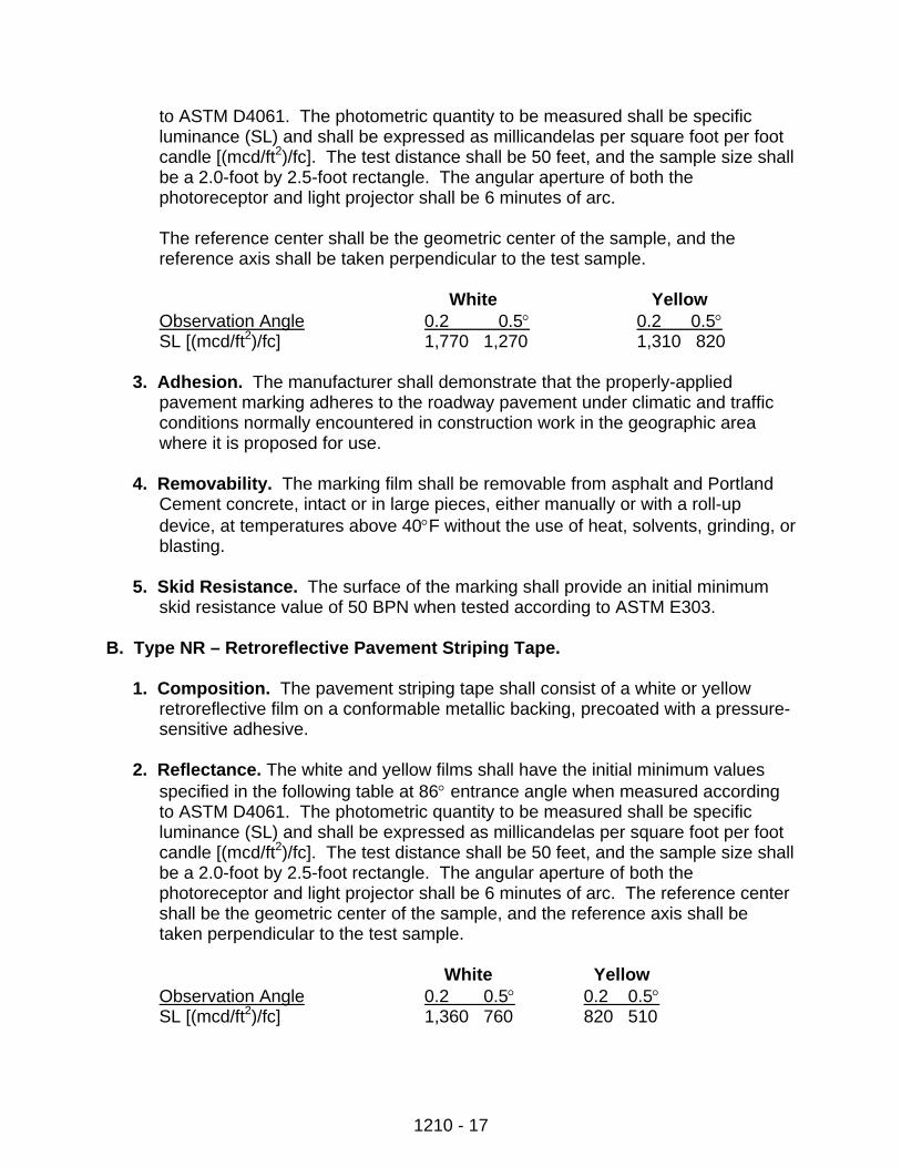
1. Composition. The pavement striping tape shall consist of a white or yellow retroreflective film on a conformable metallic backing, precoated with a pressure-sensitive adhesive.
2. Reflectance. The white and yellow films shall have the initial minimum values
specified in the following table at 86° entrance angle when measured according to ASTM D4061. The photometric quantity to be measured shall be specific luminance (SL) and shall be expressed as millicandelas per square foot per foot candle [(mcd/ft2)/fc]. The test distance shall be 50 feet, and the sample size shall be a 2.0-foot by 2.5-foot rectangle. The angular aperture of both the photoreceptor and light projector shall be 6 minutes of arc. The reference center shall be the geometric center of the sample, and the reference axis shall be taken perpendicular to the test sample.
White Yellow
Observation Angle 0.2 0.5° 0.2 0.5° SL [(mcd/ft2)/fc] 1,360 760 820 510
1210 - 18
3. Skid Resistance. The surface of the marking shall provide an initial minimum skid resistance value of 35 BPN when tested according to ASTM E303.
4. Abrasion Resistance. Samples of the test material shall not wear through to
the conformable backing surface in less than 125 cycles, when tested according to Federal Test Method Standards 141, Method 6192, modified by using an H-22 wheel and a 250 gram load.
5. Adhesion. The manufacturer shall demonstrate that the properly-applied
pavement marking adheres to the roadway pavement under climatic and traffic conditions normally encountered in construction work where proposed for use.
C. Wet Reflective Markers.
1. Composition. The marker body shall be an expanded rubber extrusion that is elastically compressed and deflected when impacted by rotating vehicle tires. When tested per ASTM D1056 for expanded rubber, the marker body shall have the following typical properties:
a. Compression deflection less than 16 psi at 25° deflection.
b. Oven aged compression deflection (% change) +18.
c. Compress set low 10%.
d. Water absorption, less than 9%.
e. Density 24 lbs./ft. The marker shall have a precoated pressure-sensitive
adhesive capable of adhering to the retroreflective top film of the performance tape.
The marker shall have a retroreflective enclosed lens sheeting element adhered to the marker body with a pressure-sensitive adhesive.
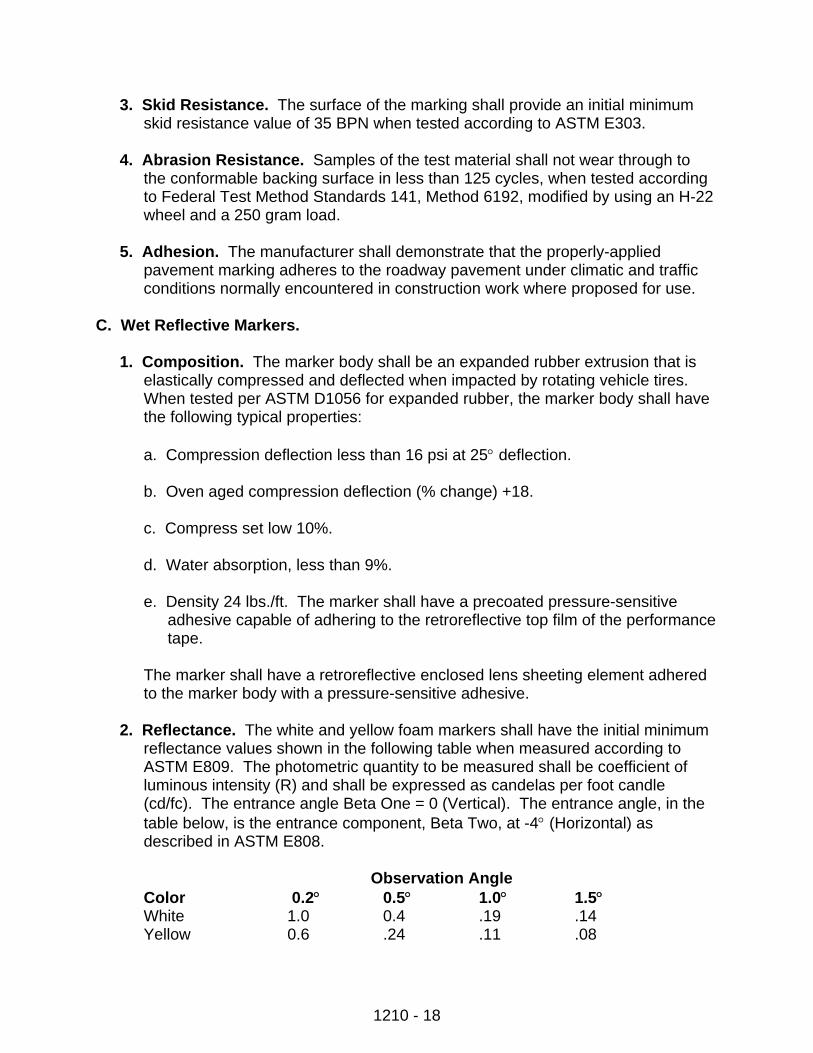
2. Reflectance. The white and yellow foam markers shall have the initial minimum
reflectance values shown in the following table when measured according to ASTM E809. The photometric quantity to be measured shall be coefficient of luminous intensity (R) and shall be expressed as candelas per foot candle (cd/fc). The entrance angle Beta One = 0 (Vertical). The entrance angle, in the table below, is the entrance component, Beta Two, at -4° (Horizontal) as described in ASTM E808.
Observation Angle
Color 0.2° 0.5° 1.0° 1.5° White 1.0 0.4 .19 .14 Yellow 0.6 .24 .11 .08
1210 - 19
For testing purposes, the retroreflective reference axis used to define the entrance angle in the Specification is considered to be the axis emanating from the center of the reflective surface of the marker and directed parallel to the base and perpendicular to the top edge of the marker when viewed from above.
The angle formed by the reflective surface and the base of the marker must be between 75° and 90° before measurement.
Reflective elements of the marker shall be visible to motorists in low beam headlamps at night at the following distances and conditions:
1,500 feet – dry 1,000 feet – at a rate of 1” of rainfall per hour 250 feet – at a rate of 8” of rainfall per hour
1210-2.10 RAISED PAVEMENT MARKERS Raised pavement markers shall consist of a plastic shell with one or more prismatic reflective faces with a minimum of 2.45 square centimeters of reflective surface for each direction required to reflect incident light. The marker shall be fitted with pressure-sensitive adhesive for application to a primed surface. The materials used shall be capable of being easily applied and removed. The CONTRACTOR shall demonstrate that the properly-applied pavement marking adheres to the roadway under climatic and traffic conditions normally encountered in the construction work zone. *Either “slow,” “medium,” or “fast dry” paint and either type of Plastic Marking Film may be used. 1210-3 EQUIPMENT Paint Applicator. The equipment required to apply pavement marking paint and glass beads shall be a self-propelled, pneumatic spraying machine with atomizing nozzles capable of applying two 4-inch to 8-inch wide lines at one time. The spray mechanism shall be operated by quick opening and closing valves. The applicator shall apply the materials at a rate specified in an even and uniform thickness with clearly defined edges. The applicator shall have reservoirs or tanks equipped with agitators that keep the material in a smooth, even mixture. Tanks shall have sufficient capacity to apply the materials as specified. The applicator shall be equipped with an automatic skip control device that applies a stripe of specified length with a linear tolerance of 3 inches. The applicator shall be equipped with a guide boom and be capable of retracing and applying materials to traffic markings in place. Adequate hand-operated equipment shall be required to place the pavement markings on areas not readily accessible to the pavement marking applicator.
1210 - 20
The machine shall be equipped with a glass bead dispenser adjusted and synchronized with the paint applicator to distribute the reflectorizing spheres uniformly on the painted line(s) using air pressure. The bead dispenser shall be equipped with an automatic cutoff control, synchronized with the cutoff of the striping material. 1210-4 CONSTRUCTION REQUIREMENTS A. General. A project layout of the pavement striping and marking shall be prepared
and submitted to the ENGINEER for approval 48 hours before any installation work. Type F paint shall be used for all painted centerline pavement marking, other than short-term pavement marking.
B. Pavement Surface Preparation.
1. General. The pavement surface in the area where markings are to be applied shall be clean and dry. Foreign materials (i.e., dirt, petroleum products, paint,
and curing compound) shall be removed from the pavement surface before applying pavement marking. The amount of pavement moisture shall be tested by taping a 12-inch by 12-inch (approximate) sheet of transparent plastic film, similar to “Saran Wrap,” to the pavement. If moisture condenses on the pavement side of the film within 15 minutes, the pavement must be dried before installing pavement markings. The moisture test will not be required when water-based pavement marking paint is used.
2. Plastic Pavement Marking Film. The pavement surface shall be cleaned by
sandblasting, power water spray, grinding, wire brushing, brooming, compressed air, or other methods to the satisfaction of the ENGINEER. New Portland Cement concrete that has curing compound on it shall be sandblasted. Costs associated with the required cleaning shall be an incidental item to payment for the plastic pavement marking film. If short-term or permanent pavement marking is encountered, removal will be paid for at the Contract Unit Price bid for Obliteration of Pavement Marking. When no bid item is provided, the cost of removing the pavement marking will be paid for as incidental.
3. Preformed Patterned Pavement Marking Film. The preformed marking shall
be capable of being adhered to asphalt concrete by a pre-coated pressure sensitive adhesive. A primer may be used to precondition the pavement surface.
4. Pavement Marking Paint. If the ENGINEER requires a cleaning method other
than air pressure, the cost of cleaning will be paid for as incidental.
5. Short-Term Pavement Marking. Short-term pavement marking shall be an application of pavement marking paint, pavement marking tape, or raised pavement markers. The surface preparation for application of the short-term pavement marking shall be the same as that required for permanent striping.
1210 - 21
C. Traffic Control.
1. Signing. The CONTRACTOR shall erect and maintain sufficient devices (cones, signs, barricades) to protect the work area from traffic interference, tracking on or damage to the cleaned pavement, and the newly applied markings. All devices used to divert traffic from the work zone shall be designed to resist displacement by wind.
2. Traffic Movement. Traffic shall be maintained through the work area at all times
according to the traffic control plan and Section 1211. Flagpersons and shadow vehicles shall be furnished when required. Two-way traffic shall be maintained on two-lane roadways, and 1/2 the roadway shall be open to traffic on multi-laned roadways at all times. Costs of furnishing, erecting, and maintaining cones, signs, and barricades, including the costs of flagging and shadow vehicles, shall be incidental to the cost of pavement marking.
3. Time Period for Control. Necessary traffic control devices shall be properly
placed and in operation before construction is allowed to start. The devices shall be kept current and placed only in the areas of actual work activities. Traffic control devices shall be kept in place until the ENGINEER approves their removal after the pavement marking has dried and is determined to be ready for traffic.
4. Operational Precautions. Equipment shall not be prepared, filled, or cleaned,
nor shall any equipment or material be stored on the roadway. These operations shall be conducted off the pavement without interfering with or endangering traffic.
D. Pavement Marking Application.
1. Pavement Marking Paint and Glass Beads.
a. Method of Application. Pavement marking paint and glass beads shall be applied separately by machine. Where machine application in an odd-shaped area is not feasible, hand application is permitted.
b. Application Dates and Temperatures. Pavement marking paint and beads
(except for temporary stripe) shall not be applied before May 1 nor after October 1 except upon written permission of the ENGINEER. Pavement marking paint shall be applied only during daylight hours when the air and pavement surface temperatures are 40°F or warmer when applying solvent-based paint or 45°F or warmer when applying water-based paint. The paint shall not be applied when the air and pavement surface temperatures are expected or forecasted to be colder (lower) than the minimum application temperature.

1210 - 22
New asphalt pavement shall be allowed to cool to a maximum temperature of 125°F and be given a minimum curing period of four hours prior to applying permanent striping.
c. Rate of Application. One gallon of paint shall cover a 4-inch wide stripe for a
length of 280 to 320 feet, depending upon pavement surface texture. The paint shall not be diluted, but a small amount of naphtha thinner may be used to flush out paint containers. Glass beads shall be evenly distributed over the wet paint stripe at a rate of at least 6 pounds per gallon of paint. Beads shall be applied using an automatic pressure dispenser. If the application rates are not within the requirements, the marking application shall be stopped until corrections are made.
d. Short-Term Pavement Marking. Pavement marking paint and beads
applied as short-term pavement marking shall be applied only during daylight hours. Application shall be made in a 4-inch width and a 10-foot length with unpainted gaps of 30 feet. The no-passing zone markings shall be made in a 4-inch width and a length as required to cover the no-passing zones. The paint and beads shall be applied as required and at the rate specified in Section 1210-4 D.1.c. Short-term pavement marking applied to the centerline shall be applied to the full length of the bituminous course and milled surface before sunset on the same day the work is accomplished. Paving or milling operations shall not resume if the short-term pavement marking has not been replaced as required.
Short-term pavement marking on the top lift shall be carefully placed with exact alignment and spacing so that the permanent striping will match when applied. Errors in alignment and spacing shall be corrected at the CONTRACTOR’s expense, or removed just before the installation of the permanent striping.
When Type NR (Not Easily Removable) short-term pavement marking is specified, pavement marking paint and beads may be used in lieu of Type NR construction zone marking film.
e. Short-Term Pavement Marking – Asphalt Seal Coat Projects. Short-term
pavement marking for asphalt seal coat projects shall consist of pavement marking paint and beads. Before sealing operations, spotting tabs shall be installed every 200 feet along the centerline and tabs shall also be placed to mark the beginning and end of the no-passing zones. The spotting tabs shall be removed by cutting the tabs flush with the roadway surface. Tabs shall not be pulled out. The cost of the spotting tabs and their installation and removal shall be incidental to the short-term pavement marking bid item.
The short-term pavement marking shall be applied before sunset each day to the full length of the roadway that received the bitumen and cover coat material that day. Seal coat operations shall not resume if the short-term
1210 - 23
pavement marking is not in place as required. The broken line at centerline of two-lane, two-way roadways (yellow) or between lanes of multi-laned roadways (white) shall be 4 inches wide and 10 feet long followed by a 30-foot unpainted gap. The solid line barrier stripe (yellow) in no-passing zones shall be 4 inches wide, and the length shall be that required to cover the entire no-passing zone. Before applying the paint and beads, the areas to receive the striping shall be lightly broomed.
If the in-place short-term pavement marking has become obscured and has lost its required visibility due to being covered, or partially covered, by cover coat or blotter material, the material shall be removed from the striped areas by light brooming or compressed air before sunset. Damage to the cover coat material and striping resulting from the removal operation shall be corrected at the CONTRACTOR’s expense.
The short-term pavement marking shall be carefully placed with exact alignment and spacing so that the permanent striping matches when applied. Errors in alignment and spacing shall be corrected at the CONTRACTOR’s expense.
One gallon of paint shall cover a 4-inch wide stripe for a length of 200 to 240 feet, as directed by the ENGINEER. Glass beads shall be evenly distributed over the wet paint at the rate of at least 6 pounds per gallon of paint.
f. Tolerances.
(1) The length of the painted stripe shall not vary more than plus or minus 3
inches from the prescribed length.
(2) The width of the painted stripe shall not vary more than plus or minus 1/2 inch from the prescribed width.
(3) The length of the painted segment and gap shall not vary more than 6
inches in a 40-foot cycle.
(4) The tolerance from the proper alignment shall not vary more than plus or minus 2 inches.
(5) Dashed lines that are painted over existing dashed lines shall begin within
6 inches of the beginning of the existing line, unless otherwise directed by the ENGINEER.
2. Plastic Pavement Marking Film.
a. General. Plastic pavement marking film applied as a permanent pavement
marking shall not be applied before June 1 nor after September 1 of any year. The permanent marking film shall not be applied when the pavement surface
1210 - 24
temperature is 50°F or colder, nor shall the film be placed over painted markings. The pavement surface and the marking film shall be prepared for installation as required for the type of film used. The film shall be lap or butt spliced when required to join 2 lengths of film, and the film shall be cut at open joints or cracks in the pavement. The cut ends shall be firmly tamped in place.
b. Plastic Pavement Marking Film Application. Application of plastic
pavement marking film, whether by contact cement or mechanical application, shall be made using the manufacturer’s recommendation.
c. Short-Term Pavement Marking. Pavement marking tape applied as short-
term pavement marking shall conform with the requirement for application of pavement marking tape. The tape shall be applied on the center line in a 4-inch width and a 10-foot length with a gap of 30 feet. The no-passing zone markings shall be made in a 4-inch width and a length as required to cover the no-passing zone. The short-term pavement marking shall be applied to the full length of the bituminous pavement and milled surface placed each day, and shall be completed before sunset each day. Paving and milling operations shall not resume if the striping is not in place as required.
Type R (Removable) or Type NR (Not Easily Removable) construction zone marking film shall be applied where specified. The film required shall be applied as specified for pavement marking film.
The CONTRACTOR shall remove the Type R marking film when required in the Contract or directed by the ENGINEER.
Pavement marking paint with beads may be used in lieu of Type NR construction zone marking film for short-term pavement marking.
3. Preformed Patterned Pavement Marking Film. Application of preformed
patterned pavement marking film shall be according to the manufacturer’s recommendation.
4. Pavement Marking Sheeting (Pressure Sensitive). This marking shall be
applied as required in the Contract or by hand or mechanical methods to a pavement surface prepared as required for all pavement marking. The delineated position on the pavement surface shall be primed using the sheeting manufacturer’s recommendations. The primed surface shall be air dried for 1 to 2 minutes before applying the sheeting. Mechanical application conforming to the sheeting manufacturer’s recommendations shall be used, unless machine application is impractical. Sheeting shall be inlaid into the pavement by roller when the pavement is warm enough to accept the pavement marking sheeting without damaging the sheeting.
1210 - 25
5. Raised Pavement Markers. Raised pavement markers shall be reflectorized. Broken lane lines and center lines on two-lane, two-way roadways shall consist of four markers on 3.33-foot centers with a 30-foot gap. Markers used for solid lines shall be spaced on 5-foot centers. Raised pavement markers used in double solid lines shall be placed side by side separated by a 4-inch gap.
New concrete pavement (pavement that has had no traffic over it for a winter season) shall have markers placed on 5-foot centers for all solid lines.
E. Inspection and Acceptance.
1. General. Markings that are discolored, damaged by wind-blown dirt, or are ineffective at night will be rejected. Unsightly markings with uneven edge lines, poor longitudinal alignment, uneven adherence, missing portions, or other objectionable faults will be rejected. All rejected markings shall be repaired, or removed, and replaced at the CONTRACTOR’s expense.
2. Maintenance of Short-Term Pavement Markings. Short-Term Pavement
Markings used on the Project will be rated according to the American Traffic Safety Services Association’s (ATSSA) Quality Standards for Work Zone Traffic Control Devices. The definition of “acceptable,” “marginal,” and “unacceptable” and the evaluation guidelines shall be as defined in ATSSA’s Quality Standards for Work Zone Traffic Control Devices.
At the time of initial set up and major phase changes, 100% of each type of short-term pavement marking (painted, tape, raised marker) shall be classified as acceptable. The CONTRACTOR shall certify in writing to the ENGINEER that all short-term pavement markings installed are classified as acceptable.
The amount of acceptable markings of each type may decrease to the limits defined in the ATSSA standards as a result of damage or deterioration during the course of work. Pavement markings evaluated as unacceptable shall be replaced within 12 hours.
Raised Pavement Markers shall be cleaned as necessary to remove dirt, mud, or other foreign material which reduces the brightness of the reflectorized sheeting.
All markings no longer required shall be removed immediately.
3. Pay Adjustment for Short-Term Pavement Markings. If the Project is not
completed and extends into winter suspension, the ENGINEER will inspect the markings before suspending the Contract; and any unacceptable markings shall be repaired before the CONTRACTOR is relieved of further liability.
If the Contract must be carried through the winter due to CONTRACTOR-caused delays, markings shall be maintained throughout winter suspension by and at
1210 - 26
the CONTRACTOR’s expense. During the maintenance period, markings which are not functioning properly shall be replaced by and at the CONTRACTOR’s expense. Failure to make these repairs will result in a reduced pay factor for the markings according to the following schedule:
% of Ineffective Striping Pay Factor Pay Factor
10-20%/mile, and not more than 200 L. Ft. 50% of Bid Price of markings missing in one continuous stretch for that mile
Over 20%/mile, or more than 200 L. Ft. of No payment for markings missing in one continuous stretch that mile
No deduction will be made for markings lost due to abrasion at approaches or due to snow removal equipment.
All markings no longer required shall be removed immediately.
1210-5 METHOD OF MEASUREMENT A. Pavement Marking-Painted Line. This item will be measured by the linear foot of
the various widths of painted line, complete, in place, and accepted. Only the painted portion of broken lines will be measured. Pavement Marking-Painted Messages will be measured by the square footage shown on the Plans, in place, and accepted by the ENGINEER.
B. Plastic Pavement Marking Film, Pavement Marking Sheeting, and Pre-
formed Patterned Pavement Marking Film. This item will be measured by the Linear Foot of the various widths of installed line, complete, in place, and accepted. Only the installed portion of broken lines will be measured. Messages will be measured by the square footage shown on the Plans, in place, and accepted by the ENGINEER.
C. Short-Term Pavement Markings.
1. Short-Term – ____-Inch Line (Painted, Tape, or Raised Markers). This item will be measured by the linear foot in place. The longitudinal gaps will not be measured. If raised pavement markers are used, the length of measurement will be the length of a pavement line that would exist if paint had been installed.
2. Short-Term – ____-Inch Line, Type R. This item will be measured by the linear
foot in place.
3. Short-Term – ____-Inch Line, Type NR. This item will be measured by the linear foot in place.
1210 - 27
4. Short-Term – Message, Type R. This item will be the square footage as shown on the Plans in place.
5. Short-Term – Message, Type NR. This item will be the square footage as
shown on the Plans in place.
The price bid for Type R marking film shall include the cost of installation and removal.
D. Raised Pavement Markers. This item will be measured by the individual unit
(Each) complete and in place. E. Obliteration of Pavement Marking. This item will be measured by the square foot
of pavement marking removed. 1210-6 BASIS OF PAYMENT Payment will be made under: Pay Item Pay Unit a. Pavement Marking Painted - ____ inch line Linear Foot b. Pavement Marking Painted – Message Square Foot c. Plastic Pavement Marking Film - ____ inch line Linear Foot d. Plastic Pavement Marking Film – Message Square Foot e. Preformed Patterned Pavement Marking - ____ inch line Linear Foot f. Preformed Patterned Pavement Marking – Message Square Foot g. Pavement Marking Sheeting - ____ inch line Linear Foot h. Pavement Marking Sheeting – Message Square Foot i. Short-Term – ____-Inch Line (painted, tape, or raised markers) Linear Foot j. Short-Term – ____-Inch Line, Type R Linear Foot k. Short-Term – ____-Inch Line, Type NR Linear Foot l. Short-Term – Message, Type R Square Foot m. Short-Term – Message, Type NR Square Foot n. Short-Term – Painted Line (Seal Jobs) Linear Foot o. Raised Pavement Markers Each p. Obliteration of Pavement Marking Square Foot This payment will be full compensation for all labor, equipment, and materials necessary to complete the work.
1211 - 1
SECTION 1211 – TRAFFIC CONTROL 1211-1 DESCRIPTION This work consists of furnishing, installing, and maintaining all required traffic control devices according to an approved traffic control plan or details shown on the Plans. This includes Specifications providing for watch persons, flaggers, pilot cars, and necessary precautions for protecting the public, the workers, and the work. All traffic control devices and their placement shall meet the standards and requirements of the “Manual on Uniform Traffic Control Devices for Streets and Highways” (MUTCD) and the “Standard Highway Signs,” published by the Federal Highway Administration. The CONTRACTOR must submit a traffic control plan to the TRAFFIC ENGINEER for approval at least two (2) weeks prior to setting up the detour closing a roadway. Press releases shall be submitted to the Engineering Department for review a minimum of three (3) days prior to each change in operation or phase. Once approved, they must be sent to local media as well as fire, police, and ambulance. Information shall include anticipated duration, detour routes, and pedestrian issues. A press release is required to announce the reopening of a detour when not otherwise notified. The CONTRACTOR is responsible for the placement and maintenance of all the work zone signs and barricades during the utility construction. All traffic control devices shall be installed and maintained in a safe and orderly manner complying with the provisions of Chapter 6 of the most recent update of the Manual on Uniform Traffic Control Devices for Streets and Highways, U.S. Department of Transportation. The CONTRACTOR is responsible for maintaining and protecting traffic during a temporary suspension of work. The CONTRACTOR shall designate a superintendent and an alternate for emergency repair service to traffic control devices. Telephone numbers for these personnel shall be provided to the Project Manager. These personnel shall be available at all time to respond an emergency. When an emergency occurs and the superintendent and alternate are not available to take protective measures, the City may authorize others to do the necessary work and deduct the cost of the work from the CONTRACTOR. 1211-2 MATERIALS AND EQUIPMENT All materials and construction details not specifically addressed in the plans, Special Provisions and Construction Specifications for Municipal Public Works, Mandan, North Dakota, shall be in conformance with Section 704 of the 2002 edition and supplements of the Standard Specifications for Road and Bridge Construction, North Dakota
1211 - 2
Department of Transportation, and the provisions of Chapter 6 of the most recent update of the Manual on Uniform Traffic Control Devices. Traffic Control Devices used on the project will be rated according to the American Traffic Safety Services Association (ATSSA) Quality Standards for Work Zone Traffic Control Devices. The definitions of “acceptable,” “marginal,” and “unacceptable” and the evaluation guidelines shall be as defined in ATSSA’s Quality Standards for Work Zone Traffic Control Devices. Payment for Traffic Control Devices, labor, plans, and maintenance shall be measured and paid by the lump sum as “Traffic Control” for each unit. A. Sign Backing Materials. Materials for sign backing shall be aluminum, steel,
plywood, or plastic of the size and thickness shown on the NDDOT Standard Drawings. Aluminum or steel backing shall meet and be processed according to Section 1211. Plywood backing shall be of exterior grade or be overlaid with a plastic coating, and processed using recommendations of the reflective sheeting manufacturer. Plastic backing shall be processed using recommendations of the reflective sheeting manufacturer.
B. Reflective Sheeting. Orange diamond-shaped, rectangular, and square signs shall
be faced with Wide Angle Prismatic Fluorescent Retroreflective Sheeting meeting Section 1212-2 G. Barricades and vertical panels shall be Wide Angle Prismatic Retroreflective Sheeting meeting Section 1212-2 F. Flexible reflective sheeting, Type III C or Type IV, shall be used on drums, cones, and tubular markers. All remaining signs and sign backgrounds shall be faced with Wide Angle Prismatic Retroreflective Sheeting meeting Section 1212-2 F.
C. Flexible Roll-Up Sign. The flexible roll-up sign shall be mounted in a sturdy frame
to keep the sign flat and in proper position for viewing by the motorist. The frame shall be attached to a portable stand for placement on the road bed. The stand shall be weighted or designed to provide stability against wind. Flexible roll-up signs shall be fabricated to meet Section 1212-2 E.2.
D. Flat Sheet Sign Faces. All flat sheet sign faces, except for flexible roll-up signs as
provided above, shall be fabricated to meet Section 1212-1. E. Barricades. Barricades shall be constructed of lightweight materials. They shall be
the type and length shown on the Standard Drawings.
Both sides of the barricade rail surface shall be covered with reflective sheeting as specified.
1. Wood Rails. Wood rails shall meet the Standard Rules of the American Lumber
Standards. Application of reflective sheeting directly on wood rails shall be
1211 - 3
made only after all edges and surfaces have been properly sanded, cleaned, sealed, resanded, and painted with a prime coat. The painted surface on which the reflective sheeting is applied shall be treated as specified by the reflective sheeting manufacturer. In lieu of treating the painted surface to receive the reflective sheeting, sheet aluminum having a minimum thickness of .040 inches may be attached to the barricade rails with non-rust fasteners. The aluminum sheet shall be fabricated and degreased as provided in Section 1211 before applying reflective sheeting.
2. Aluminum Rails. Aluminum rails shall be an extrusion of the size and shape
shown on the Standard Drawings and shall meet ASTM Designation B221, Alloy 6063-T6. They shall be fabricated and degreased as provided in Section 1211 before applying reflective sheeting.
F. Delineator Drums. Drums shall be approximately 36 inches in height and a
minimum of 18 inches in diameter at the top. They shall be constructed of durable plastic with horizontal, circumferential, orange and white reflectorized stripes as shown on the Standard Drawings. The reflectorized stripes shall be fabricated from Type III C or Type IV flexible reflective sheeting as provided in Section 1212-2. Delineator drums shall be weighted with sand placed at the bottom of the drum or constructed so that they can not be blown over or displaced by wind or passing traffic, and do not create a hazard if accidentally struck.
G. Traffic Cones. The cones shall be orange in color, shall be a minimum of 28 inches
in height with a broadened base, and fabricated from materials that withstand impact. For nighttime use, cones shall have a minimum 6-inch wide white flexible reflectorized band placed a minimum of 3 inches; but not more than 4 inches from the top. An additional 4-inch white reflectorized band shall be placed a minimum of 2 inches below the 6-inch band. The cones shall be weighted at the base to prevent overturning by the wind.
H. Tubular Markers. Tubular markers shall meet the dimensions, color configuration,
and installation details as shown on the Standard Drawings. I. Vertical Panels. The vertical panels shall meet the dimensions, striping
configuration, and colors shown on the Standard Drawings. The panels shall be fabricated as specified for flat sheet signs in Section 1211.
J. Delineators. Each delineator shall consist of an acrylic plastic or reflective sheeting
reflector mounted on a post support according to the Standard Drawings. K. Portable Barriers. Portable barriers shall be constructed of concrete. The barrier
shall meet the details on the Plans or Standard Drawings. L. Warning Lights. Warning lights shall be portable, lens directed, enclosed lights.
Warning lights shall meet the requirements of the Institute of Traffic Engineers
1211 - 4
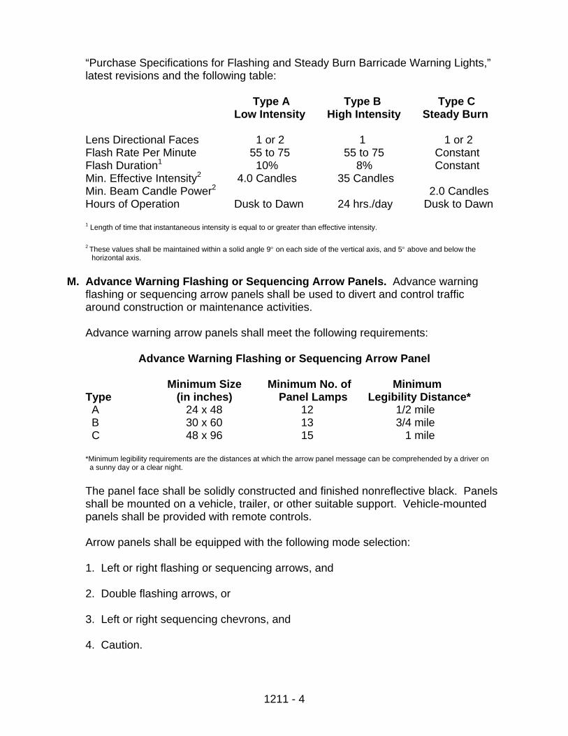
“Purchase Specifications for Flashing and Steady Burn Barricade Warning Lights,” latest revisions and the following table:
Type A Type B Type C Low Intensity High Intensity Steady Burn
Lens Directional Faces 1 or 2 1 1 or 2 Flash Rate Per Minute 55 to 75 55 to 75 Constant Flash Duration1 10% 8% Constant Min. Effective Intensity2 4.0 Candles 35 Candles Min. Beam Candle Power2 2.0 Candles Hours of Operation Dusk to Dawn 24 hrs./day Dusk to Dawn 1 Length of time that instantaneous intensity is equal to or greater than effective intensity. 2 These values shall be maintained within a solid angle 9° on each side of the vertical axis, and 5° above and below the horizontal axis.
M. Advance Warning Flashing or Sequencing Arrow Panels. Advance warning
flashing or sequencing arrow panels shall be used to divert and control traffic around construction or maintenance activities.
Advance warning arrow panels shall meet the following requirements:
Advance Warning Flashing or Sequencing Arrow Panel
Minimum Size Minimum No. of Minimum
Type (in inches) Panel Lamps Legibility Distance* A 24 x 48 12 1/2 mile B 30 x 60 13 3/4 mile C 48 x 96 15 1 mile *Minimum legibility requirements are the distances at which the arrow panel message can be comprehended by a driver on a sunny day or a clear night.
The panel face shall be solidly constructed and finished nonreflective black. Panels shall be mounted on a vehicle, trailer, or other suitable support. Vehicle-mounted panels shall be provided with remote controls. Arrow panels shall be equipped with the following mode selection:
1. Left or right flashing or sequencing arrows, and
2. Double flashing arrows, or
3. Left or right sequencing chevrons, and
4. Caution.
1211 - 5
Automatic light dimming controls capable of reducing rated lamp voltage a minimum of 50 percent shall be provided on each arrow panel. The dimming shall be controlled by a photoelectric cell which activates at sunup and sundown. The flashing rate of the lamps shall not be less than 25 nor more than 40 flashes per minute. Minimum lamp “on” time shall be 50 percent for the flashing arrow and 25 percent for the sequential chevron.
The arrow panel lamps or lenses shall be recess-mounted or alternately equipped with an upper hood of not less than 180°. The color of the light emitted shall be yellow.
N. High-Level Warning Device. This warning device shall consist of a minimum of 3
flags and, when specified, a Type B high-intensity flashing light. The distance from the roadway to the bottom of the flasher lens or the lowest point of all 3 flags shall be at least 8 feet. The flags shall be a minimum of 16 inches square and shall be orange or fluorescent red-orange in color.
O. Temporary Construction Zone Marking and Temporary Striping. The temporary
marking and striping shall meet Section 1210. P. Flagging. STOP/SLOW Sign Paddles shall meet the details specified in the
Standard Drawings. The paddle shall be fastened to a rigid handle of 5 to 8 feet in length. The paddle shall be fabricated from light semirigid material, and be octagonal in shape. To improve conspicuity, the paddles may be supplemented by one or two symmetrically positioned, alternately flashing, white high-intensity lamps on each side.
When nighttime flagging is required, sufficient auxiliary lighting shall be used to illuminate the flagging station. This lighting shall be supplied by the CONTRACTOR and set up in such a manner so that drivers are not blinded by it. A flashlight with a red transparent glow cone, reflectorized clothing, and a reflectorized stop-slow paddle are required for nighttime flagging operations.
1211-3 CONSTRUCTION REQUIREMENTS A. General. The CONTRACTOR shall furnish, install, and maintain all required traffic
control devices, and shall provide watchpersons and flaggers as necessary to protect the work and to ensure public and workers’ safety. All required control devices shall be available for installation when needed and shall be maintained, relocated, covered, or removed as necessary. Standards for flagging shall be as specified in Section 1211-3 X.
When work zone signs placed as shown on the Standard Drawings interfere with permanent signs, the work zone signs shall be moved to locations that afford the best results. Messages shall be varied as required.
1211 - 6
If the CONTRACTOR has not furnished, installed, located, maintained, or removed one or more traffic control devices as required, the ENGINEER may direct work to cease until the deficiencies have been corrected.
Traffic control devices shall be operated only as long as they are needed. Only those devices that apply to existing conditions shall be in place.
The traffic control devices shall have breakaway supports that meet the requirements of the AASHTO Roadside Design Guide Chapter 4 Section 4.1. All signs on fixed supports shall be placed on breakaway supports, unless they are located behind a barrier or crash cushion. The CONTRACTOR shall provide documentation showing that these requirements are being met for any sign supports used that do not comply with the NDDOT’s Standard D-754-8.
Barricade rails and panels with stripes which begin at the upper right side and slope downward to the lower left side are designated as “right” panels and are to be used on the right side of a traffic lane. Stripes which begin at the upper left side and slope downward to the lower right side are designated as “left” panels and are to be used on the left side of a traffic lane.
B. Project Terminal Signing. Before work is started, the required traffic control
devices shall be erected at each end of the project and at various locations within the Project as shown on the traffic control Plan drawings. These control devices shall remain in place and be maintained for the duration of the Project. The ENGINEER may direct their removal during winter or other lengthy periods of suspension.
C. Work Area Signing. Appropriate traffic control devices as shown on the traffic
control Plan drawings shall be erected and maintained for each type of work area required by the operations. When no details are provided for the particular type of construction situation involved, traffic control devices shall be installed according to the MUTCD or as directed by the ENGINEER. No construction work shall be started until the proper traffic control devices for the work area are in place. If the CONTRACTOR’s construction operations or sequence requires additional signing, flaggers shall be furnished at the CONTRACTOR’s expense or construction operations shall be suspended in that area until the condition is corrected and the required signs have been installed.
When traffic is carried through the construction area, two-way traffic shall be maintained when practicable. One-way traffic shall be directed by flagpersons or maintained under control of an approved traffic signal system. All signs and other control devices shall indicate actual conditions and shall be relocated, removed, or changed, as conditions require. Signs necessary only during hours when work is actually being performed shall be removed or completely covered when no work is in progress.
1211 - 7
Portable sign mountings shall be as shown on the Plans or as approved by the ENGINEER. Portable signs shall be used when construction operations in an area are temporary. Temporary operations are those that are less than 24 hours in duration. At times when portable signs are not required, they shall be moved to a minimum of 45 feet from the edge of the traveled lane or laid down on the inslope. Signs laid down on the inslope shall have stand bases constructed so the signs and bases can be placed flat with no portions of the sign or base projecting upward from the inslope more than 6 inches.
D. Existing Signs. Existing regulatory traffic signs which must be moved to
accommodate construction shall be immediately reset.
The cost to remove and reset existing traffic signs to accommodate construction shall be included in the price bid for other items.
E. Route Markers. Route marker signs required for the Project and for
CONTRACTOR-maintained detours will be furnished by the CONTRACTOR and shall be installed by the CONTRACTOR on supports furnished by and at the CONTRACTOR’s expense.
F. Detour Signing. The CONTRACTOR shall furnish, install, and maintain all traffic
control devices for detours. G. Highways Closed to Traffic. When a detour is provided and traffic is not
maintained through the construction area, necessary access to property abutting the Project shall be provided by constructing and maintaining temporary roads and approaches from the nearest crossroad. Traffic shall not be routed over detours not provided in the Contract documents without written authorization from the ENGINEER.
H. Restricted Speed Zones. Restricted speed zones and the speed limit to be posted
for such zones will be designated in the Contract documents or determined by the ENGINEER.
I. Temporary Suspension. During a temporary suspension of work, the
CONTRACTOR is responsible for maintaining and protecting traffic. When operations are suspended for the winter, the roadway and the traffic control devices will be maintained by and at the CONTRACTOR’s expense. Before suspending operations for the winter, adequate approaches shall be constructed to all crossroads or intersecting roads which have been disturbed by construction operations. Access to the roadway from abutting property shall also be provided. Warning signs, barricades, and other traffic control devices shall be erected (or existing devices removed) as directed by the ENGINEER. Resetting of signs removed because of a winter suspension will not be measured for payment.
J. Barricade Application. Type I or Type II barricades shall be used as shown in the
traffic control plan details where traffic is maintained through the construction area.
1211 - 8
They may be used singly or in groups to mark a specific hazard, or used in a series to channelize traffic and shall not be set parallel to traffic. On high-speed roads or in situations where barricades may be overturned in the wind, the barricades shall be stabilized with sandbags placed on the lower parts of the frame or stays.
When a section of road is closed to traffic, Type III barricades shall be erected at the points of closure. They shall extend completely across the roadway and shoulders or from curb to curb. Where provision must be made for access of equipment and authorized vehicles, the Type III barricades shall be provided with gates or movable sections that can be closed when work is not in progress, or with indirect openings that discourages public entry. Where access is provided through the Type III barricade, an employee shall be designated to assure proper closure at the end of each working day.
When a road or street is closed, but access to local traffic must be furnished, the Type III barricades shall be arranged to permit local use but discourage through traffic. A sign with the appropriate legend concerning use by local traffic shall be installed.
Type III barricades shall be installed at the beginning and end of the project when so indicated in the Contract documents and shall not be placed parallel to traffic.
The required warning signs shall be mounted above the barricades.
If the construction zone encroaches onto sidewalks or crosswalks and pedestrians cannot be diverted to other walkways, barricades may be used to define the path.
K. Drum Application. Drums shall be used to channelize or delineate traffic flow and
may be used singly or in groups to mark specific hazards. When drums are placed in the roadway, advance warning signs are required.
L. Traffic Cone and Tubular Marker Application. Traffic cones and tubular markers
used to channelize traffic shall have adequate stability to prevent overturning or displacement by wind. Additional weighting may be required but shall not be so heavy to cause a hazard if struck.
M. Flexible Delineator Application. Flexible delineators used to channelize traffic
and separate two-way traffic shall be located and attached as shown in the Contract documents.
N. Vertical Panel Application. Vertical panels shall be used as channelizing devices,
warning devices, or windrow markers. Vertical panels shall be faced on both sides. O. Delineator Application. Delineators shall be used in construction areas for
guidance, to indicate roadway alignment, and to outline the required vehicle path. Delineators shall not be used as warning devices and, when used in a construction zone, shall be combined with approved warning devices.
1211 - 9
Delineators shall be mounted on supports so the reflector is 4 feet above the roadway edge. White reflectors shall be used for delineators installed along the right side of the street or highway. Yellow reflectors shall be used for delineators installed along the left edge of divided streets, divided highways, and one-way roads.
Delineator spacing shall be as indicated on the traffic control plan sheets. Along roadway curves, delineators shall be spaced so that several delineators are always visible to the driver.
P. Portable Barrier Application. Traffic control plan sheets may require, or the
CONTRACTOR may elect to use, portable barriers to separate the work area from the traffic area. For nighttime use, the barriers shall be supplemented by standard delineators or channelizing markings or devices.
When specified, warning lights shall be installed on continuous barriers. The first two warning lights on each side of the roadway shall be Type A flashers, and subsequent lights on the barrier shall be Type C steady burn lights. The ends of the barrier shall be protected by crash cushions or by flaring the barrier ends away from the traveled way as shown in the Contract.
Q. Lighting Device Application. Lighting devices shall be provided as required on the
traffic control plan sheets to supplement signs, barricades, and other traffic control devices.
1. Type III or IV Reflective Sheeting. Flashing lights and steady burn lights on
signs, drums, vertical panels, and barricades are not required when Type III or Type IV reflective sheeting is used.
2. Flashing Lights (Type A, Low-Intensity). Type A low-intensity flashers shall
be used to warn drivers that they are approaching or traveling in a hazardous area.
3. Flashing Lights (Type B, High-Intensity). Traffic control plan sheets require
installation of high-intensity flashers at extremely hazardous site conditions. The high-intensity flashers shall be operated 24 hours per day.
4. Steady-Burn Lights (Type C). The steady-burn warning lights shall be used to
delineate the edges of the traveled way on detour curves, on lane changes, and along tapers. Spacing of steady-burn lights shall be as indicated on the traffic control plan sheets.
5. Mounting Height of Warning Lights. The mounting height of warning lights
shall be as follows:

1211 - 10
a. Barricade and Portable Standards. A minimum height of 36 inches from the bottom of the lens to the roadway.
b. Signs. The bottom of the light housing shall not be less than 2 inches nor
more than 12 inches above the top of the sign.
c. Vertical Channelizing Devices and Independent Supports. The light shall be at least 4 feet and not more than 5 feet above the pavement.
6. Advance Warning Arrow Panels. The sequencing arrow panels shall be used
to provide advance warning and directional information to assist in diverting and controlling traffic around construction activities being conducted on or adjacent to the traveled way. Other traffic control devices may be required in conjunction with the sequencing arrow panel. During nighttime operation of the flashing arrow panels, the lamps shall be automatically dimmed to 50 percent of the output.
7. Floodlights. If construction activities are performed at night, floodlighting shall
be provided for the construction area and flagger stations. The area must be adequately illuminated without creating glare in the eyes of drivers.
R. High-Level Warning Device. High-level warning devices shall be used to
supplement other controls and devices and shall be required in urban high-density traffic situations.
S. Pavement Marking Removal. Removal of existing marking and installation of
temporary marking shall be as shown on the traffic control plan sheets. Inappropriate existing markings shall be removed and the new delineation placed before opening the affected lane or lanes to traffic. Removal of pavement markings shall not permanently damage the surface or texture of the pavement. Painting over existing stripes is not permitted. Where blast cleaning is used for removal of markings or other objectionable material, the sand or other blast material left on the pavement shall be removed immediately.
T. Construction Zone Marking. Yellow temporary marking shall be used to delineate
traffic flow in opposing directions or mark the left edge of the pavement of divided highway or one-way roads. White temporary marking shall be used to delineate the separation of traffic flow in the same direction or mark the right edge of the pavement. The temporary markings shall be used in combination with appropriate warning signs, channelizing devices, and delineation to clearly indicate the required vehicle paths.
U. Traffic Control Personnel.
1. Traffic Control Supervisor. When called for on the Plans, the CONTRACTOR shall designate a qualified traffic control supervisor. This supervisor shall be in addition to the watchperson specified in Section 1211-3 U.2. If this traffic control
1211 - 11
supervisor becomes unavailable on the project, the CONTRACTOR shall designate a qualified replacement supervisor.
a. Qualifications. The traffic control supervisor shall:
(1) Have completed an NDDOT-approved comprehensive course of study based on Part VI of the MUTCD and furnish proof thereof.
(2) Be familiar with the requirements of NDDOT traffic control plans and
specifications.
(3) Have a total of at least 12 months field experience with traffic control plans, layouts, and maintenance.
(4) Be competent to supervise personnel in traffic control operations.
b. Duties. The traffic control supervisor shall:
(1) Provide traffic control as required by the plans, specifications, MUTCD, or as directed by the ENGINEER.
(2) Supervise the installation, operation, inspection, maintenance, and
removal of the traffic control system.
(3) Correct traffic control conditions that cause erratic vehicle movements, unexpected braking, etc.
(4) Propose changes to improve traffic flow through the work zone.
(5) Be accessible to the job site within one hour of notification and be “on call”
on a 24-hour basis.
(6) Provide the ENGINEER with documentation of all traffic control activities required in # (2) above.
(7) Function as watchperson in his/her absence.
c. Traffic Control Course. The course prescribed in Section 1211-3 U.1.a(1)
above shall be the American Traffic Safety Services Association (ATSSA) 20-hour course, or the 3-day National Highway Institute (NHI) Course 38003, Design and Operation of Work Zone Traffic Control, or equal.
An equal course shall include the following subjects: Manual and Standard Signs used in Work Areas (3 hours); Channelizing Devices and Temporary Barriers, Pavement Markings, Lighting Devices, Arrow Displays and Special Devices, and Devices Location and Placement (4 hours); Layout for Traffic Control Devices, Motorist Characteristics, and Options and Alternatives (4
1211 - 12
hours); Installation and Removal of the Traffic Control Zone, and Operation and Maintenance of the Traffic Control Zone (4 hours); Flagging Operations, Legal Liability and Record Keeping, and Emergency Situations (5 hours).
Workshops shall be included in the above time frames covering (a) design problems, (b) installation and removal, and (c) operations and maintenance. Each session shall also include a question and answer period.
2. Watchpersons. Watchpersons shall be provided to patrol the project to assure
that the traffic control devices are properly placed in accordance with the traffic control plans and standards. The project shall be patrolled daily at least once during daylight before 10 a.m. and at least once during darkness after 10 p.m., including weekends and days when no work is in progress. The CONTRACTOR shall provide written documentation to the ENGINEER of the watchperson’s hours and activities.
The CONTRACTOR shall immediately assist the watchperson, whenever needed, to correct conditions that cause erratic traffic movement, unexpected braking, etc., and erect, repair, replace, or relocate the required traffic control devices. Emergency assistance shall be provided to motorists, when needed, due to roadway conditions. Suspension of watchperson service may be permitted during periods of authorized suspension or after substantial completion of the work, provided the job site is in safe condition.
V. Emergency Control. Written notification shall be provided to the ENGINEER, the
State Police, and local law enforcement agencies of the names, addresses, and telephone numbers of the CONTRACTOR’s Superintendent and an alternate. Either the Superintendent or the alternate shall be on call for notification of any emergencies that may arise during periods when construction operations are not in progress. Changes in the designation of the Superintendent or the alternate shall immediately be made known, in writing, to the ENGINEER and the law enforcement agencies.
The CONTRACTOR’s Superintendent or alternate, or traffic control foreman shall meet with the ENGINEER before work commences to review traffic control plans, and shall be available at all times to periodically discuss modifications to the traffic control plan with the ENGINEER or his representative.
When an emergency occurs and the Superintendent or alternate are not available to take protective or corrective measures, the Department will authorize others to do the necessary work and deduct the cost of the work from the CONTRACTOR.
W. Maintenance of Traffic Control Devices. Traffic Control Devices used on the
Project will be rated according to the American Traffic Safety Services Association’s (ATSSA) Quality Standards for Work Zone Traffic Control Devices. The definitions of “acceptable,” “marginal,” and “unacceptable” and the evaluation guidelines shall be as defined in ATSSA ’s Quality Standards for Work Zone Traffic Control Devices.
1211 - 13
At the time of initial set up and major phase changes, 100 percent of each type of device (signs, barricades, vertical panels, drums, cones, tubular markers, warning lights, arrow panels, etc.) shall be classified as acceptable. The CONTRACTOR shall certify in writing to the ENGINEER that all traffic control devices installed are classified as acceptable.
For signs, barricades, vertical panels, drums, cones, tubular markers, and arrow panels the number of acceptable devices of each type may decrease to 75 percent of the initial quantity as a result of damage or deterioration during the course of work. The remaining 25 percent of each type of devices may be in the marginal category. Warning lights shall be “acceptable” or “marginal” at the limits defined in the ATSSA standards. All unacceptable devices found on the job site shall be replaced within 12 hours.
Traffic control devices not covered by the evaluation guidelines shall be maintained to operate effectively and be in good repair.
Traffic control devices shall be cleaned as necessary to remove dirt, mud, or other foreign material which reduces the brightness of the reflectorized sheeting or warning lights.
X. Flagging. Flaggers shall be clean, neat, and fully dressed at all times while on duty
either day or night. For daytime work, the flagger’s vest, shirt, or jacket shall be orange, yellow, strong yellow green, or fluorescent versions of these colors. For nighttime work, similar outside garments shall be retroreflective. The retroreflective material shall be orange, yellow, white, silver, strong yellow-green, or a fluorescent version of one of these colors and shall be visible at a minimum distance of 1,000 feet. The retroreflective clothing shall be designed to identify clearly the wearer as a person and be visible through the full range of body motions.
Each flagger shall be furnished with the booklet, “Instructions to Flaggers,” and shall observe the rules and regulations contained therein. The CONTRACTOR shall obtain copies of these instructions from the Department.
Flaggers shall not be assigned other duties while working as authorized flaggers.
The CONTRACTOR is responsible for providing trained flaggers. All flaggers must view a flagging video training tape and pass a flagging written examination before performing flagging on the project. The CONTRACTOR will acknowledge in writing, before any flagging work begins on the project, that all flaggers will have viewed a flagging video tape and passed a written examination before performing flagging on the project.
Y. Pilot Car. A pilot car shall be used to guide vehicles through or around the
construction area when traffic is reduced to a single lane. The pilot car operation
1211 - 14
must be coordinated with flagging operations or other controls at each end of the one-lane section.
Z. Flag Application. Flags shall be attached to warning signs if indicated in the traffic
control plan sheets. 1211-4 METHOD OF MEASUREMENT A. Individual traffic control items shall include furnishing, installing, maintaining,
relocating, and removing as dictated by the work in progress and will be measured for payment as follows:
1. Traffic Control Signs. Traffic Control Signs will be measured by the unit and
will be inventoried when complete, in place, and accepted by the ENGINEER. All posts and mounting hardware required to complete the installation will be included in the pay item. The total units of Traffic Control Signs shown in the Plans is estimated and may be adjusted according to the needs of the Project.
2. The following devices will be measured by the number of each installed,
complete, in place, and accepted by the ENGINEER:
a. Barricades (by type)
b. Delineator Drums
c. Traffic Cones
d. Delineators
e. Flexible Delineators
f. Vertical Panels
g. Sequencing Arrow Panels (by type)
No measurement will be made of devices which are installed without being authorized by, or directed by, the ENGINEER.
B. Traffic Control. When “Traffic Control” is included in the Contract as a lump sum, it
includes all traffic control necessary for the project construction except as otherwise provided. Payment includes furnishing, installing, and maintaining the required signs, barricades, and other warning devices; relocating or removing devices as dictated by the work progress; and providing watchpersons to patrol the work.
No payment (over the lump sum bid for “Traffic Control”) will be authorized for additional traffic control devices required as a result of the CONTRACTOR’s method
1211 - 15
or sequence of operation, whether or not the type of operation is included in the typical work area layouts shown on the traffic control plan sheets.
Payment (over the lump sum bid for “Traffic Control”) may be authorized for additional traffic control devices if the type or number of such devices requested by the ENGINEER exceeds the requirements indicated by the typical work area layouts shown on the traffic control plan sheets, or when the need for additional traffic control devices is created as a result of Contract revisions.
C. Obliteration of Pavement Marking. Obliteration of Pavement Marking will be
measured according to Section 1210-5 E., and paid for according to Section 1210-6. D. Flagging. Flagging will be measured by the hour of authorized flagging. Authorized
flagging shall be the actual hours of flagging authorized by the ENGINEER. 1211-5 BASIS OF PAYMENT A. When the item “Traffic Control” is bid as a Lump Sum, payment for the Contract
Lump Sum bid will be made according to the following schedule:
Total Payment to Date 40% - When all initial traffic control devices required to start
construction have been installed. 50% - When Contract is 25% complete. 75% - When Contract is 50% complete. 90% - When Contract is 75% complete. 100% - When Contract is complete.
When additional traffic control devices requested by the ENGINEER qualify for payment according to Section 1211-4 B, payment for furnishing and installing such devices will be made using the prices listed in the “Rental Rates for Equipment and Traffic Control Devices” published by the Department.
The above payments for installation include the cost of removing or relocating the traffic control devices. No additional payment will be made when traffic control devices are covered up, or temporarily taken out of service, then returned to use.
All standard traffic control devices furnished by the CONTRACTOR shall remain the property of the CONTRACTOR.
If the CONTRACTOR is required to furnish special non-standard signs not shown on the Plans, payment will be made at invoice price plus 15 percent, and the sign will become the Department’s property after it has been removed from service. Payment for sign supports and installation of special signs will be made using the prices listed in the “Rental Rates for Equipment and Traffic Control Devices” published by the North Dakota Department of Transportation.
1211 - 16
B. Obliteration of Pavement Marking, when included in the Contract as a separate
pay item, will be paid for according to Section 1210-6.
When no pay item is provided, the Obliteration of Pavement Marking will be paid for under Section 104-3 D.
C. Flagging will be paid for at the Contract Unit Price per hour for the total authorized
hours of flagging as measured in Section 1211-4 D. D. Pilot Car will be paid for at the Contract Unit Price per hour for the total hours
authorized by the ENGINEER. E. Short-Term Pavement Markings, when included in the Contract as separate pay
items, will be paid for at the Contract Unit Price under Section 1210-6. F. Items requested by the ENGINEER that are not listed on the Plans or Standard
Drawings as incidental items or separate pay items such as Flashing and Steady Burn Lights, Concrete Median Barriers, Attenuation Devices, etc., will be paid for under Section 104-3 D.
G. The cost of providing Traffic Control Supervisors, when needed, and Watchpersons
will be incidental to the prices bid for other items.
1212 - 1
SECTION 1212 – HIGHWAY SIGNS AND POSTS 1212-1 DESCRIPTION This work item consists of furnishing, fabricating, and installing highway signs, delineators, and supporting structures. 1212-2 MATERIALS A. General. All materials furnished and used in this work shall be new and shall meet the Plans, the NDDOT Standard Drawings, Section 1212 of the Standard
Specifications,and the following requirements:
Signs, supporting structures, breakaway bases, anchor units, brackets, stringers, and hardware shall be fabricated to meet the dimensions, metal gauge, and bolt holes set forth in the Contract and NDDOT Standard Drawings. All flat sheet sign backings shall be aluminum with reflective sheeting applied as specified.
The traffic control sign details not otherwise specified shall meet the MUTCD published by the Federal Highway Administration.
All sign faces shall be according to the detail drawings and the alphabets shown in the MUTCD, Standard Highway Signs, and Standard Alphabets, published by FHWA. Sign faces not detailed in these publications shall meet the detailed drawings shown in the supplementary Standard Highway Signs booklet published by the NDDOT.
Regulatory, warning, and guide signs shall be detailed and dimensioned according to detailed drawings of the Standard Highway Signs booklet. These detail drawings are available to the sign fabricator upon request from the NDDOT. Signs not illustrated in these booklets shall be as shown on the NDDOT Standard Drawings. The last number in the sign numbers shown is the width of the sign required.
Variable message sign dimensions have been computed by the North Dakota Department of Transportation in order to draft these signs by mechanical means. These message computations have been tabulated and shall be used to lay out these sign faces in the fabricator’s shop. These tabulated sheets will be furnished to the CONTRACTOR upon request after the Contract has been awarded.
B. Concrete. Concrete used in this item of work shall be Class AE Portland Cement
concrete mixed and proportioned as specified in Section 500. C. Reinforcing Steel. The reinforcing steel shall meet Section 501-2.9. D. Delineators. Delineators shall meet Section 1212-6.
1212 - 2
E. Hardware and Fittings. Signs, supporting structures, breakaway bases, anchor units, brackets, stringers, and all hardware and fittings shall meet Section 1212-5 A.
F. Posts. Posts shall meet Section 1212-5 B. 1212-3 CONSTRUCTION REQUIREMENTS A. Locating and Positioning Signs and Sign Structures. Each sign and structure
shall be located according to the Plans or, where necessary, for maximum effect of the sign. Installed signs and structures will be inspected at night for maximum effect and minimum specular reflection. If any sign exhibits specular reflection or is ineffective at night, the sign shall be adjusted at the CONTRACTOR’s expense.
Signs and delineators located less than 30 feet from the pavement edge shall be erected with the sign face truly vertical and turned 93° away from the center and direction of travel of the lane which the facility serves. Signs located 30 feet or more from the edge of the pavement edge shall be erected with the sign face truly vertical and aligned 90° from the center and direction of travel of the lane which the offset sign serves. Special attention shall be given to the location and positioning of signs and delineators at the point where lanes divide, or on curves, to avoid specular reflection and to obtain maximum effectiveness of the facility.
B. Sign Fabrication.
1. General. All sign backing for flat sheet signs shall be aluminum unless noted otherwise, with reflective sheeting applied as specified herein. On large variable message signs the messages, symbols, and borders shall consist of directly applied reflective sheeting cut to desired shapes. The message, symbols, and border shall be applied as specified by the sheeting manufacturer.
2. Fabrication of Sign Backing. Sign backings shall be cut to size and shape
and shall be free of buckles, warps, dents, cockles, burrs, and all defects resulting from fabrication. The surface of all signs shall be plane surfaces. All cutting, shearing, and drilling or punching of holes (except mounting holes for demountable letters, numerals, symbols, and borders) shall be completed before metal degreasing and application of reflective sheeting.
3. Cleaning and Processing. Cleaning and processing of sign backing shall
take place before applying the reflective sheeting. Cleaning and processing shall be performed using the sheeting manufacturer’s instructions and recommendations as well as the requirements of Section 1212.
All metal sign backing material shall be handled only by handling devices or clean canvas gloves between cleaning and applying reflective sheeting. Metal shall not come in contact with greases, oils, or other contaminants before application of reflective sheeting. When backing materials are chromate-conversion coated beforehand and are allowed to set for several days before
1212 - 3
applying reflective sheeting, the application surface shall be given a solvent wipe before reflective sheeting application.
4. Fabrication of Flat Sheet Signs. The background of the flat sheet signs shall
be screened on reflective sheeting as specified by the manufacturer of the reflective material and as specified herein. Messages, symbols, and borders may be screened on or directly applied reflective sheeting. Directly applied reflective sheeting shall be applied as specified by the sheeting manufacturer. Colors shall meet the requirements of the Contract and as shown in the MUTCD. Care shall be taken so screening inks are compatible with reflective sheeting backgrounds.
Reflective material shall meet Section 1212-2.
The reflective sheeting used on flat sheet sign backings larger than the manufacturer’s material shall require splicing. All sheeting on each individual sign shall be from the same manufacturer’s lot, and shall be spliced in one direction only. No more than one splice will be permitted per sign. Vertical splices shall be in the center of the sign. Horizontal splices, if used in lieu of the vertical splice, shall be in the center of the sign with the top portion overlapping the bottom portion of the sheeting when it is in the upright position.
Heat-activated, adhesive-coated, reflective sheeting may be overlapped not less than 3/16 inch or by a butted gap not to exceed 1/32 inch. Splices will be permitted only on sign screens processed with transparent colors. Pressure-sensitive, adhesive-coated, reflective sheetings shall be overlapped not less than 3/16 inch.
The overlapped splice shall be made without screening paints between the reflective sheeting.
The sign face shall be processed and finished with material as specified by the sheeting manufacturer. Processing of Type III A or III B Reflective Sheeting with screened-on messages shall be accomplished before applying to the sign backing. Processing of Type II Reflective Sheeting may be accomplished before
or after applying to the sign backing.
The finished signs shall have a smooth, uniform surface. All letters and numbers shall be clear cut and sharp.
5. Fabrication of Panel Signs. The background shall be applied to the panels
as specified by the reflective sheeting manufacturer.
Reflective sheeting shall be overlap spliced. The splice shall be overlapped not less than 3/16 inch, and sheeting applied to panels shall extend over the edges and down the side legs a minimum of 1/16 inch. Splices shall be at a 90° angle to the length of the panel. The splices shall be uniformly and neatly made
1212 - 4
throughout their entire length. No individual panel shall have more than two splices, and the minimum distance between adjacent splices shall be 8 feet.
When guide sign symbols (e.g., handicap, hospital, and airport symbol signs) are required on larger guide signs as part of the message, the symbol signs shall be riveted to the larger signs and be installed at the locations shown on the plans. The cost of the symbol signs and the labor, equipment, and material needed to attach them will not be bid separately, but will be included in the price bid for the panel or overlay of the sign.
6. Date of Fabrication. All signs receiving new sign facings shall be dated with the
month and year fabricated. The date shall be placed on the back of the metal backing on the lower corner of sign near the edge closest to traffic so that it can be read from the ground. The dating layout shall consist of 1/4 inch high numbers on a 2 1/4 inches long by 1 3/4 inches high pressure-sensitive label. The numbers imprinted on the upper part of the label shall be 1 through 12, with the last two digits of four consecutive years printed across the bottom (as 92, 93, 94, 95). The month and year of fabrication shall be punched out. The label shall meet Section 1212-4. The cost of furnishing, fabricating, and installing labels shall be included in the price bid for “Flat Sheet for Signs Type II and III A,” “Panel for Signs Type II and III A,” “Refacing Signs Type II and III A,” or “Overlay Panel Type II and III A.”
C. Packaging, Labeling, Handling, and Shipping.
Completed signs shall be dry before packaging or storing. Packaged signs that become wet before use shall not be used. A warning label with instructions designed to prevent damage to the signs shall be on the outside of the package, and an additional warning label shall be placed in the packages between the first and second sign, before the last sign, and after each five signs in a package. Packaged signs shall not be banded and shall be stored and shipped on edge.
Packaging shall be done so that the signs are protected during storage, shipping, and handling. Packaged signs shall be slipsheeted using the material and methods recommended by the sheeting manufacturer.
Unmounted reflective sheeting may be stacked flat to a maximum height of 5 inches for temporary storage. Otherwise, they shall be stored on edge. The sheeting on signs shall not be exposed to temperatures above 150°F. The slipsheeting shall be left on the sign face until mounted.
Panel signs may be assembled or separated into sections for ease in handling, storing, and shipping. In lieu of packaging, the sign faces may be turned toward each other and fastened together firmly with sufficient spacers to prevent the sign faces from touching. Sign faces that cannot be protected by packaging or fastening face to face shall have protective covers placed over them.
1212 - 5
D. Label (Handling, Storage, and Installation Instructions). The label referred to in Section 1212-3 C shall contain the following instructions:
1. Loading on Vehicles. Signs shall be secured vertically in racks to prevent them
from rubbing, scratching, or marring front surfaces. Signs that have protective wrappings or slipsheeting shall be kept dry.
Signs shall be carefully unloaded, stacked on edge off the ground in an upright position.
2. Storage at Job Site. Signs shall be stored indoors and upright on edge to
prevent damage to the reflective sheeting.
Signs shall be kept dry. Packaged signs that get wet will be rejected.
3. Installation.
a. Signs shall be handled carefully and not scuffed or walked on.
b. Nylon washers shall be used between flat washers and sign face for all Type III and IV reflective sheeted signs.
c. When washing signs is necessary, a soft bristle brush or sponge and water
shall be used. E. Erection of Sign Supports and Delineators.
1. General. The ENGINEER will verify the support lengths on all new sign supports prior to the materials being ordered by the CONTRACTOR. All sign supports shall be firmly set and plumb after erection. All concrete foundations shall be constructed as specified, with the top sloped enough to drain away from the sign support. All exposed concrete above ground surface shall be given a rubbed finish. Excess excavation material removed to set sign supports shall be disposed of at the CONTRACTOR’s expense. A driving cap shall be used when driving a sign support.
2. Delineator Posts. Delineator posts shall be driven without being damaged. If
the drilled or punched hole method is used, the hole shall be large enough so the post can be set without damage. Any damage to utilities or structures as a result of construction operations shall be repaired at the CONTRACTOR’s expense.
3. Anchor for Telescoping Perforated Tubes and Flange Channel Supports.
Anchors for telescoping perforated tubes and flange channel supports shall be driven. The perforated tube anchor shall be driven to a maximum of 4 inches above the ground or sidewalk and 4 inches maximum installed height above ground or sidewalk for flange channel anchor.
1212 - 6
Anchors shall be installed at Plan length, unless the ENGINEER determines a shorter length is sufficient due to good soil bearing developed when driving the anchor. Anchor lengths may be reduced to a minimum of 3 feet. When set in sidewalk, the anchor plate may be omitted.
The sidewalk shall be cored to install the anchor unit and the cored area shall be filled with new concrete to restore the sidewalk surface.
4. Tubular Sign Supports. Tubular Sign Supports shall be set in a Class AE
Portland Cement Concrete base, constructed as shown on the Plans. Breakaway base plates shall be assembled with the bolts torqued to Plan requirements. The plates shall be carefully placed so the tapered bolt slot tapers toward approaching traffic. Either the stub post or the anchor bolt design may be used as detailed. If the anchor bolt design is used, a Portland Cement Grout shall be used to raise the top of the foundation to a snug fit under the base plate. When standard round pipe posts are shown on the Plans for signs that have two or more posts, the CONTRACTOR may elect to use either round sign supports or W-shape posts. Signs with one post shall use the round sign supports as shown on the Plans.
5. Splicing. Splicing is permitted on telescoping and flange channel posts only
to obtain the required post length. A splice shall be more than 5 feet above ground, and only one splice is permitted per post. Splicing costs shall be at the CONTRACTOR’s expense. The weight of the splice will not be added to the post pay weight.
6. W-Shaped Sign Supports.
a. The CONTRACTOR shall install H-Pile footings for W-Shaped Sign Supports
constructed as shown on the Plans. Breakaway base plates shall be assembled with the bolt torqued to Plan requirements. The plates shall be carefully placed so the tapered bolt slot tapers toward approaching traffic. W-Shaped Supports shall use the stub post design.
b. Flame Cutting of W-Shape Posts. The gas cutting torch may be used for
cutting metals or preparing joints. Carbon steel above 0.30 percent carbon, high alloy steels, heat treated steel, and plated metals shall not be flame cut unless subsequent corrective treatment is provided as approved by the Materials and Research Engineer.
All flame cutting work shall be done by the oxyacetylene gas method or other method approved by the ENGINEER. The maximum permissible deviation from true lines shall be 1/16 inch. Repairs of edge defects shall be done according to Section 3.2 of AWS Structural Welding Code, as amended by AASHTO Specifications for Welding of Structural Steel Highway Bridges. In general, the roughness of flame cut surfaces shall be no greater than an
1212 - 7
ANSI roughness value of 1000 microinches. All slag from flame cutting shall be completely removed.
When flange plates or other members are cut to a curve, the curve shall be uniform to the radius required. A series of straight cuts tangent to the curve shall not be acceptable.
When ends of members which are to take bearing are cut with a torch, a suitable allowance in their length shall be made to permit proper milling or planing.
Joints for welding may be prepared by “flame cutting” or “flame gouging” provided all slag and oxidized metals are removed.
c. Edge Finishing. Members formed to specific size by shearing of structural
steel plates having a thickness of 1/2 inch or more, shall be machined or planed to correct size by removing not less than 1/4 inch of metal. All field splice plates and stiffeners less than 1/2 inch in thickness shall have a minimum of 1/8 inch of metal removed by machining or planing after shearing.
F. Mounting Flat Sheet Signs Type III A and III B Sheeting. Flat sheet signs shall be
bolted to the supports and shall have a nylon washer between the flat washer and the sign face. Rubber incased washers may be substituted for nylon washers on work zone traffic control signs specified under Section 1211.
G. Removing and Resetting Signs and Supports. Existing signs and supports shall
be removed and reset as specified. All signs and supports not to be reset shall be stockpiled on the Project Right-of-Way at designated locations. The stockpiled signs and supports shall remain the Department’s property.
Removed or reset signs and supports that become damaged during removing, resetting, or stockpiling shall be replaced at the CONTRACTOR’s expense.
Existing signs and supports shall be removed as construction progresses, and shall be immediately reset or installed. The CONTRACTOR shall install new signs or reset signs as shown on the Plans. All signs and supports shall be on the Project site at the time construction begins. The CONTRACTOR may choose to temporarily reset existing signs, or temporarily install new signs. The cost of installing and resetting signs temporarily shall be included in the price bid for other items. Any damaged signs or supports shall be replaced at the CONTRACTOR’s expense.
H. Remove Sign Foundations. This item consists of removing signs, steel pipe
supports, and concrete foundations or piling and restoring the surface to match the surrounding area. Concrete foundations shall be removed to a depth of 2 feet below the ground line unless otherwise specified in the Plans. The signs, steel pipe
1212 - 8
supports, piling, and concrete foundations removed shall become the property of the CONTRACTOR and be disposed of outside the highway right-of-way.
I. Revise Fuse Joints. This item consists of removing the existing front fuse plate
and back hinge plate and installing a new front perforated fuse plate and a new back hinge plate as shown on the detail sheets in the Plans. All nuts will be tightened securely, torquing is not required.
J. Overlay Panel Sign Refacing. This item consists of removing the legend, border,
and symbol on those signs that have demountable copy and place overlay panels on the signs. Those signs that have direct applied reflective sheeting legends, borders, and symbols need not have these removed. The new changed legends, borders, and symbols shall be direct applied to the thin metal overlay panels and installed on the existing signs. The legends, borders, and symbols are deemed not salvageable and shall be disposed of by the CONTRACTOR outside the highway right-of-way.
The overlay panels shall be fabricated from 0.063-inch aluminum alloy conforming to ASTM B209 Alloy 6061-T6 or 5052-H38 with mill finish. The overlay panels shall be fabricated according to Section 1212-1 and degreased, etched, and coated according to Section 1212-1 of these specifications. The reflective sheeting applied to the overlay panels shall meet the requirements of Section 1212-2 of these specifications.
The letters, numerals, symbols, and borders shall be directly applied according to Section 1212.04. The Reflective sheeting shall meet the requirements of Section 1212-2. Type IIIA reflective sheeting letters, numerals, symbols, and borders shall be used on Type II background. Type IIIA reflective sheeting letters, numerals, symbols, and borders shall be used on Type IIIA background. The overlay panels, after fabrication, shall be installed on the existing signs with aluminum blind fasteners 5/32 inch diameter with 1/8 inch out the back of the existing sign backing or other non-corrosive fasteners approved by the ENGINEER. The panels are to be butted together with no overlap. Where legends, numerals, symbols, and borders cross the butt joints, they will need to be cut.
Signs that are to be overlaid that are larger than manufactured overlay panels shall be fabricated as follows: Overlay panels shall be a minimum of 18 inches wide and a maximum of 4 feet wide. Panels will have a minimum length of 8 feet. If the overlay panels do not cover the full height of the sign, the overlay panels shall be placed on the lower portion of the sign first so the longer side of the panel is vertical. The remaining panels shall be placed above these panels with their long side placed horizontally. The overlay panels shall be riveted around the panel with the rivets 1 inch from the edge of the panel. The rivets shall be evenly spaced with no more than 12 inches between rivets, horizontally and vertically. Panels more than 24 inches wide shall be riveted down the middle of the panel at 12-inch centers.
1212 - 9
K. Auxiliary Signs. The auxiliary signs used with route markers shall be the same background color as the route markers they are used with. (Interstate – Blue, State – White, Interstate Business Loop – Green, and County – Blue.)
L. Road Closed, Type III Barricade, Snow Fence Combination. This item consists of a diamond grade Road Closed Sign R-11-2-48, 3 post mounted to a Type III Barricade per NDDOT detail D-754-32 Assembly No. 37. The barricade shall be anchored 4 feet deep with minimum 2-inch x 2-inch perforated tubes per NDDOT detail D-754-18. Orange plastic safety fence shall be installed with steel fence posts spaced 8 feet apart and behind the road closed sign. The barricade shall be installed across the entire width of the proposed street, curb to curb. This combination shall be set no more than 10 feet beyond the end of the pavement. M. Relocate Road Closed, Barricade, Fence Combination. This item consists of removing and resetting combination as specified in 1212-3(L), including replacing any damaged items. 1212- 4 METHOD OF MEASUREMENT A. Flat Sheets, Panels, and Extruded Aluminum Panels. Flat sheets, panels, and
extruded aluminum panels for signs will be measured to the closest 1/10 square foot, complete, in place, and accepted by the ENGINEER. All hardware, stringers, and brackets required to attach signs to the posts shall be included in the pay item.
B. Galvanized Steel Posts.
1. Galvanized Steel Posts –Telescoping Tube and Flange Channel. Telescoping Tube and Flange Channel posts will be measured by the linear foot, complete, in place, and accepted by the ENGINEER. All sizes will be measured and paid for as “Galvanized Steel Posts – Telescoping Perforated Tube or Flange Channel.”
The post length shall be measured from the top of the post to the bottom of the anchor unit, as shown on the Plans. The sleeves and breakaway base, if included, will not be measured for payment, but will be considered incidental to the cost of the post.
2. Galvanized Steel Posts – Standard Pipe (single). Single post signs will be
measured by the linear foot of each size installed and accepted by the ENGINEER. The post length shall be measured from the top of the breakaway base to the top of the post, as shown on the Plans. The concrete base will be paid for separately.
3. Galvanized Steel Posts – W-shaped Posts (two or more). W-shaped posts
will be measured by the linear foot of each size installed and accepted by the

1212 - 10
ENGINEER. The post length, the 12-foot driven pile length, and the 2-foot stub post, as shown on the Plans, will be included in the length of post to be measured and paid for.
C. Breakaway Bases. Breakaway bases for standard pipe, W-shape, and telescoping
tubes will not be measured, and all hardware, stub posts, slip bases, and assembly will not be measured but will be incidental to the Contract Unit Price bid for posts.
D. Delineators. The quantity will be measured by the number of delineators of each
type installed, complete with reflectors. E. Concrete Foundation. When concrete foundations are used on single post signs,
the concrete will be measured by the cubic yard based on the quantity shown for each foundation complete, in place, and accepted by the ENGINEER. Reinforcing steel will not be measured but shall be included in the price bid for concrete.
The splices, post caps, plates, bolts, cutting fuse joints, and assembly will not be measured but will be incidental to the post.
F. Reset Sign Panels. The quantity to be paid for will be measured by the number of
locations at which a sign, or a sign assembly, has been reset. Signs and assemblies will be measured in place and accepted by the ENGINEER.
G. Reset Sign Supports. The quantity to be paid for will be measured by the number
of supports installed, complete, and accepted by the ENGINEER. H. Removed Signs and Supports. Removed signs and supports will not be
measured for payment, but will be incidental to other bid items. Cost of removal shall be included in the price bid for other items.
I. Remove Sign Foundations. The item “Remove Sign Foundations” will be
measured by the number of foundations removed. The quantities measured will be paid for at the Contract Unit Price, and will be full compensation for all labor, equipment, and material necessary to complete the removal and disposal.
J. Revise Fuse Joint. The item “Revise Fuse Joint” will be measured by the number
of fuse joints revised. The quantities measured will be paid for at the Contract Unit Price and will be full compensation for all labor, equipment, and material necessary to complete the work.
K. Overlay Panel. The item “Overlay Panel” will be measured by the square foot of
panel in place and accepted by the ENGINEER. The quantities measured will be paid for at the Contract Unit Price and shall include all labor, equipment, and material needed to complete the work.
1212 - 11
L. Road Closed, Barricade, Fence. This item, "Road Closed, Barricade, Fence," will be measured and paid per each combination complete in place and accepted by the ENGINEER.
M. Relocate Road Closed, Barricade, Fence. This item shall be measured and paid
per each relocation complete in place and accepted by the ENGINEER. 1212-5 BASIS OF PAYMENT Payment will be made at Contract Unit Prices for the following: Pay Item Pay Unit Flat Sheet for Signs, Type II, III A, or III B Reflective Sheeting Square Foot Panel for Signs -Type II, III A, or III B Reflective Sheeting Square Foot Extruded Aluminum Sign Panels Type III A, and III B Reflective Sheeting Square Foot Delineators, Type A, B, C, D, or E Each Class AE Concrete – Sign Foundations Cubic Yard Reset Signs Each Reset Sign Supports Each Galvanized Steel Posts – Telescoping Perforated Tube or Flange Channel Linear Foot ____” Galvanized Steel Post – Standard Pipe (Single Post) Linear Foot ____” Galvanized Steel Posts (two or more) Linear Foot Remove Sign Foundations Each Revise Fuse Joint Each Overlay Panel Square Foot This payment will be full compensation for all labor, equipment, and materials necessary to complete the work. 1212-5 SIGN BACKING MATERIAL A. Materials.
1. Flat Sheet Aluminum. Flat sheet aluminum shall be an alloy meeting ASTM B209 alloy 6061-T6, or 5052-H38 with mill finish.
2. Extruded Aluminum Panels. Extruded Aluminum Panels shall meet ASTM
B221 Alloy 6063-T6. The panels shall be furnished in 12-inch and 6-inch sections as shown on the Plans. All panels shall be flat and straight within commercial tolerances established by the aluminum industry.
1212 –11a
B. Shop Surface Preparation and Processing. All sign backing shall be clean and
free of rust, white rust, oil, and dirt. The holes shall be shop drilled to the sizes and at locations shown in the Contract. Holes required in the sign backing shall not be field drilled.
1. Degreasing. The extruded aluminum panels shall be rubbed with a clean white
cloth after degreasing and if any sticky material shows up on the cloth, the panels shall be degreased again. All aluminum sign backing shall be degreased by one of the following methods:
a. Vapor Degreasing. Aluminum materials shall be immersed in a saturated
vapor of trichloroethylene. Trademark printing shall be removed with a lacquer thinner or a controlled alkaline cleaning system.
b. Alkaline Degreasing. The aluminum shall be immersed in an alkaline
solution controlled and titrated according to the solution manufacturer ’s recommendations. The immersion time shall be dependent upon the gauge of the metal and the amount of soil to be removed.
2. Etching. All sheet aluminum shall be etched after degreasing. Extruded
aluminum panels which have a roughened surface texture suitable for paint or sheeting shall not be etched after degreasing unless the ENGINEER determines the panels are unsuitable. Etching shall be performed by one of the following methods:
1212 –12
a. Acid Etch. The aluminum shall be etched in a 6 percent to 8 percent solution of phosphoric acid at 100°F, or a proprietary acid etching solution. It shall be rinsed after etching with cold running water followed by a hot water rinse.
b. Alkaline Etch. The aluminum shall be etched in an alkaline solution
controlled by titration. The length of time the aluminum is etched and the temperature and concentration of the solution shall comply with the solution manufacturer’s instructions. The aluminum shall be well rinsed after etching. Smut on the aluminum shall be removed with an acidic chromium solution recommended by the solution manufacturer and then well rinsed.
3. Coating. Aluminum panels that have not had reflective sheeting applied for
several days or longer, after being etched, shall be treated with a light, tightly adherent chromate conversion coating before applying the reflective sheeting. The chromate conversion coating shall be free of powdery residue and shall range in color from a silvery iridescence to a pale yellow. The coating shall meet ASTM B449, Class 2, 10-35 milligrams/square foot with a median of 25 milligrams/square foot as an optimum coating weight.
4. Drying. All sign backing material shall be dried with forced hot air after
preparation and processing. 1212-6 RETRO-REFLECTIVE SHEETING MATERIALS A. General. The retroreflective sheeting stored under normal conditions shall be used
within one year from the manufactured date. The packaging cartons or roll goods shall be marked with the manufacturer’s lot numbers and manufacture date.
The surface of the barricade rails, drums, or cones shall be treated as recommended by the sheeting manufacturer before applying the reflective sheeting.
Type III C reflective sheeting shall have an identification symbol on the surface to differentiate it from other types of sheeting. The identification symbol shall not interfere with the function of the sheeting, but shall be visible to inspectors day or night without the use of special devices. The symbol shall be in a repeat pattern such that any 4-inch by 8-inch or 5-inch by 5-inch piece of the sheeting contains at least one full symbol.
The durability of the retroreflective sheeting shall be substantiated by the following accelerated weathering tests:
1. Accelerated Outdoor Test. When the retroreflective sheeting is processed and
applied according to recommended procedures, the sheeting shall be weather-resistant, resistant to dirt and fungus accumulation, and following cleaning, shall show no discoloration, cracking, crazing, blistering, or dimensional change, and have not less than 50% for Type II and IV sheeting and not less than 80% for Type III A sheeting of the specified minimum brightness values shown in
1212 – 13
ASHTO M268 measured at an observation angle of 0.2° and an entrance angle of -4° when exposed to accelerated weathering for 30 months, south-facing, unprotected at 45°.
2. Accelerated Machine Test. The retroreflective sheeting shall meet the artificial
weathering requirements of AASHTO M268 measured at an observation angle of 0.2° and an entrance angle of -4°.
The CONTRACTOR shall furnish written evidence showing conformance with one of the following:
a. The accelerated outdoor test, done in North Dakota or in a state located at
lower latitudes, or
b. The accelerated machine test and 3 years of performance in the field with no problems.
The CONTRACTOR shall secure from the manufacturer all warranties and guarantees with respect to materials, parts, workmanship, or performance which the products covered by the proposal bear, and include these warranties and guarantees with the certification.
B. Type II and III A Retroreflective Sheeting Material. Type II and III A retroreflective
sheeting shall meet AASHTO M268 and the following:
Processed retroreflective sheeting shall be applied to approved sign base material and cleaned according to manufacturer’s recommendations for use on traffic control signs. The CONTRACTOR shall furnish a written assurance that the sheeting will meet the requirements of the following tables throughout the satisfactory performance life and be effective for its intended purpose when viewed from a vehicle.
TYPE II RETROREFLECTIVE SHEETING
Average Minimum Candelas per foot Candle per sq. ft. at Satisfactory
Sheeting Type 0.2° divergence and Performance And Color -4° incidence* Life
Silver-White #1 30.0 5 years Silver-White #2 36.0 5 years Yellow 20.0 5 years Red 5.0 5 years Blue 2.0 5 years Green 3.0 5 years Orange 10.0 5 years Brown 0.4 5 years
1212 – 14
TYPE III A RETROREFLECTIVE SHEETING
Average Minimum
Candelas per fort Candle per sq. ft. at Satisfactory
Sheeting Type 0.2° divergence and Performance And Color -4° incidence* Life
Silver-White 200.0 10 years Green 36.0 10 years Yellow 136.0 10 years Red 36.0 10 years Orange 80.0 3 years Blue 16.0 10 years
*Candlepower measurement shall be made, following sign cleaning, in accordance with procedure recommended by the sheeting manufacturer.
C. Type III B Retroreflective Sheeting. Type III B retroreflective sheeting shall
consist of optical lens elements adhered to a synthetic resin and encapsulated by a flexible transparent plastic that has a smooth outer surface. The sheeting shall have a pre-coated adhesive protected by an easily removable liner. This sheeting is intended for use on rigid substrate signs and barricades used in the construction work zone. Type III B retroreflective sheeting shall meet AASHTO M268 and the following:
The CONTRACTOR shall furnish a written assurance that the sheeting will meet the requirements of the following table throughout the satisfactory performance life and be effective for its intended purpose when viewed from a vehicle:
TYPE III B RETROREFLECTIVE SHEETING
Average Minimum
Candelas per foot Candle per sq. ft. at Satisfactory
Sheeting Type 0.2° divergence and Performance And Color -4° incidence* Life
White 200 3 years Yellow 136 3 years Orange 80 3 years Prestriped Barricade 200/80 3 years
*Candlepower measurement shall be made, following sign cleaning, in accordance with procedure recommended by the sheeting manufacturer.
The impact resistance shall be tested on reflective sheeting, applied according to
1212 – 15
the manufacturer’s recommendations to a cleaned, etched aluminum panel of Alloy 6061 T 6,0.063 inches by 3 inches by 5 inches and conditioned for 24 hours at 0°C.
The sheeting to be tested for flexibility shall be conditioned for 24 hours at 0°C.
D. Type III C Retroreflective Sheeting. Type III C retroreflective sheeting shall
consist of optical lens elements adhered to a synthetic resin and encapsulated by a flexible transparent plastic that has a smooth outer surface. The sheeting shall have a pre-coated adhesive protected by an easily removable liner. This sheeting is intended for use on plastic reboundable devices such as drums and flexible delineation posts. Type III C retroreflective sheeting shall meet the weathering requirements of AASHTO M268, Type IV and the following:
The CONTRACTOR shall furnish a written assurance that the sheeting will meet the requirement of the following table and be effective for its intended purpose when viewed from a vehicle.
TYPE III C RETROREFLECTIVE SHEETING
Average minimum Candelas per foot candle per square foot.
Observation Entrance Angle Angle White Yellow Orange
0.2° -4° 250 170 100 0.2° +30° 150 100 60 0.5° -4° 95 62 30 0.5° +30° 65 45 25
The impact-resistant aluminum panel shall be the same as Type III B reflective sheeting.
The impact resistance shall be tested on a Gardner Variable Impact Tester, I6-1120 using a 4-pound weight with a 5/8-inch rounded tip dropped from a 100 inch-pound setting.
Type III C reflective sheeting performance on reboundable plastic substrates shall be measured using the following test:
The device shall be impacted 3 times by a 4,000 pound vehicle, with a 20-inch bumper, at 40 mph. Each impact shall be a direct hit (glancing blows will not be allowed). After the impacts, the reflective sheeting shall be considered performing satisfactorily when no loss of sheeting results and there is no visible change in day and night performance (when viewed from 500 feet).
The sheeting to be tested for flexibility shall be conditioned for 24 hours at 0°C.
1212 – 16
E. Type IV Reflective Sheeting. The Type IV reflective sheeting shall consist of high-gloss transparent ultra-violet light-stabilized polyester film bonded to a layer of polyester cube corner prisms with not less than 40,000 prisms per square inch meeting AASHTO M268 and the following:
1. Type IV, Class 1 Reflective Sheeting. The backing for the polyester sheeting
used on barricade rails, drums, and traffic cones shall be an opaque-white plasticized polyester film not less than 0.004 inch thick with an adhesive backing meeting AASHTO M268, Class 1.
2. Flexible Rollup Sign, Non-Adhesive Backing Fabric. The polyester sheeting
on the flexible rollup portable signs shall be coated on both sides with orange pigment polyester and shall meet the following specifications:
Base Fabric Fiber 1,000 denier polyester Weight 3 ounces/square yard Fabric Count 10 warp, 10 fill
Coated Fabric Total Weight 14 ± 1/2 ounces/square yard Type of Coating PVC Color Orange Distribution 60 face, 40 back Federal Standard
Mechanical Properties 191 Method
Tensile Strength Warp 250, Fill 200 5100 Tear Strength Warp 85, Fill 95 5134.1 Low Temperature -65°F High Temperature Continuous +180°F Abrasion Resistance (Taber) 1700 Cycles 5306 Flame Resistance California Fire
Marshall Approved Reg. No. F 102.4
F. Wide Angle Prismatic Reflective Sheeting. The sheeting shall consist of prismatic
lenses formed in a transparent synthetic resin, sealed, and backed with an aggressive pressure sensitive adhesive protected by a removable liner. The sheeting shall have a smooth surface with a distinctive interlocking diamond seal pattern and orientation marks visible on the face.
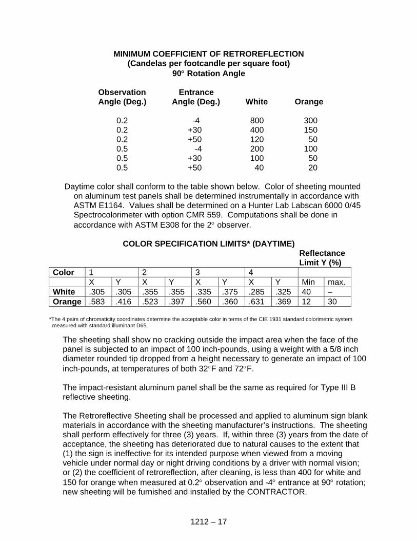
1212 – 17
MINIMUM COEFFICIENT OF RETROREFLECTION (Candelas per footcandle per square foot)
90° Rotation Angle
Observation Entrance Angle (Deg.) Angle (Deg.) White Orange
0.2 -4 800 300 0.2 +30 400 150 0.2 +50 120 50 0.5 -4 200 100 0.5 +30 100 50 0.5 +50 40 20
Daytime color shall conform to the table shown below. Color of sheeting mounted
on aluminum test panels shall be determined instrumentally in accordance with ASTM E1164. Values shall be determined on a Hunter Lab Labscan 6000 0/45 Spectrocolorimeter with option CMR 559. Computations shall be done in accordance with ASTM E308 for the 2° observer.
COLOR SPECIFICATION LIMITS* (DAYTIME)
Reflectance Limit Y (%)
Color 1 2 3 4 X Y X Y X Y X Y Min max. White .305 .305 .355 .355 .335 .375 .285 .325 40 – Orange .583 .416 .523 .397 .560 .360 .631 .369 12 30
*The 4 pairs of chromaticity coordinates determine the acceptable color in terms of the CIE 1931 standard colorimetric system measured with standard illuminant D65.
The sheeting shall show no cracking outside the impact area when the face of the panel is subjected to an impact of 100 inch-pounds, using a weight with a 5/8 inch diameter rounded tip dropped from a height necessary to generate an impact of 100 inch-pounds, at temperatures of both 32°F and 72°F.
The impact-resistant aluminum panel shall be the same as required for Type III B reflective sheeting.
The Retroreflective Sheeting shall be processed and applied to aluminum sign blank materials in accordance with the sheeting manufacturer’s instructions. The sheeting shall perform effectively for three (3) years. If, within three (3) years from the date of acceptance, the sheeting has deteriorated due to natural causes to the extent that (1) the sign is ineffective for its intended purpose when viewed from a moving vehicle under normal day or night driving conditions by a driver with normal vision; or (2) the coefficient of retroreflection, after cleaning, is less than 400 for white and 150 for orange when measured at 0.2° observation and -4° entrance at 90° rotation; new sheeting will be furnished and installed by the CONTRACTOR.
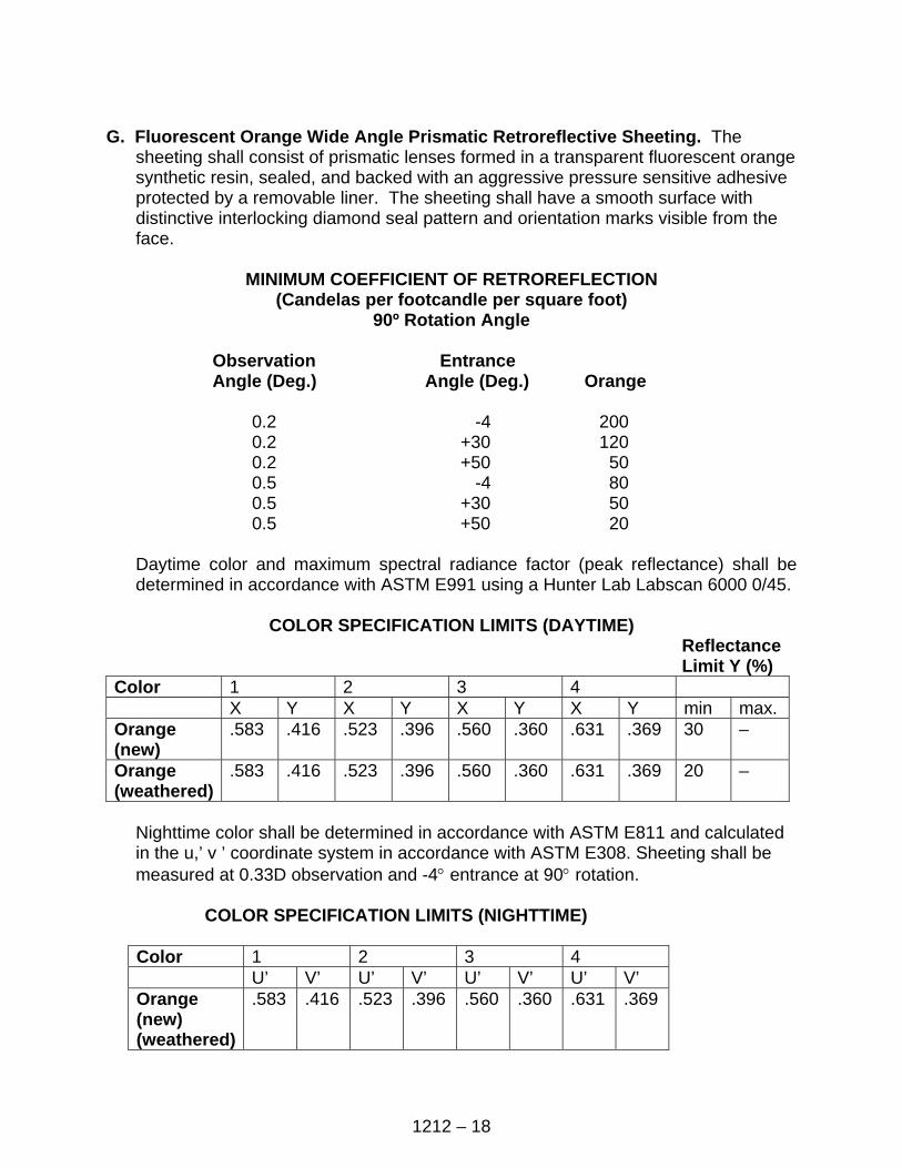
1212 – 18
G. Fluorescent Orange Wide Angle Prismatic Retroreflective Sheeting. The
sheeting shall consist of prismatic lenses formed in a transparent fluorescent orange synthetic resin, sealed, and backed with an aggressive pressure sensitive adhesive protected by a removable liner. The sheeting shall have a smooth surface with distinctive interlocking diamond seal pattern and orientation marks visible from the face.
MINIMUM COEFFICIENT OF RETROREFLECTION
(Candelas per footcandle per square foot) 90º Rotation Angle
Observation Entrance
Angle (Deg.) Angle (Deg.) Orange
0.2 -4 200 0.2 +30 120 0.2 +50 50 0.5 -4 80 0.5 +30 50 0.5 +50 20
Daytime color and maximum spectral radiance factor (peak reflectance) shall be determined in accordance with ASTM E991 using a Hunter Lab Labscan 6000 0/45.
COLOR SPECIFICATION LIMITS (DAYTIME)
Reflectance Limit Y (%)
Color 1 2 3 4 X Y X Y X Y X Y min max. Orange (new)
.583 .416 .523 .396 .560 .360 .631 .369 30 –
Orange (weathered)
.583 .416 .523 .396 .560 .360 .631 .369 20 –
Nighttime color shall be determined in accordance with ASTM E811 and calculated in the u,’ v ’ coordinate system in accordance with ASTM E308. Sheeting shall be measured at 0.33D observation and -4° entrance at 90° rotation.
COLOR SPECIFICATION LIMITS (NIGHTTIME)
Color 1 2 3 4 U’ V’ U’ V’ U’ V’ U’ V’ Orange (new) (weathered)
.583 .416 .523 .396 .560 .360 .631 .369
1212 – 19
The sheeting impact resistance requirements shall be the same as in Section 1212-2 F.
The impact-resistant aluminum panel shall be the same as that required in Section 1212-2 F.
The field performance requirements shall be the same as specified in Section 1212-2 F., except that coefficient of refraction for the fluorescent sheeting can be no lower than 100.
1212-7 PIGMENTED PLASTIC FILM, PRESSURE-SENSITIVE ADHESIVE A. Description. This material shall be flexible, pigmented plastic film completely
precoated with a pressure-sensitive adhesive. The adhesive shall be protected by a treated paper liner which shall be removable without soaking in water or other solvents. The material shall be available in colors listed in Section 1212-3 B.7.
B. Material Requirements. Material requirements shall be as follows:
1. Thickness. The thickness of the plastic film with adhesives shall be a minimum of 0.003 inch and a maximum of 0.0045 inch.
2. Film. The unapplied and applied film shall be readily processed and shall
ensure adequate adhesion with process or printed inks recommended by the manufacturer.
3. Flexibility. The material shall be sufficiently flexible to permit application over
and conformance to moderately-contoured surfaces.
4. Gloss. The film shall have a minimum initial 60° gloss value of 35 when tested according to ASTM D523, measuring at least 3 portions of the film to obtain uniformity.
5. Adhesive. The precoated adhesive shall form a durable bond to smooth, clean,
corrosion-resistant, and weather-resistant surface; shall be of uniform thickness; shall be non-corrosive to applied surfaces; and shall have no staining effect on the film. The adhesive shall adhere securely at temperatures of -30°F to +200°F; shall not crack, chip, or peel voluntarily; nor shall it be removed from the panel in one piece without the aid of a tool.
6. Sunlight Resistance. There shall be no effect on the adhesive tack or
performance following exposure of the adhesive face under a new General Electric RS Sunlamp for a period of 6 hours at a distance of 8 inches.
7. Exterior Exposure. The unprocessed material shall withstand the years of
exposure, listed below by color, in a vertical, south facing exterior exposure in Texas. During the exposure, the unprocessed material shall show no

1212 – 20
appreciable discoloration, cracking, crazing, blistering, delamination, or loss of adhesion. A slight amount of chalking is permissible. The CONTRACTOR shall furnish a written assurance from the manufacturer that the sheeting will meet the requirements of the following table and be effective for its intended purpose when viewed from a vehicle, throughout the satisfactory performance life:
Satisfactory Performance
Color Life
White 7 years Black 7 years Yellow 5 years Aluminum 5 years Insignia Blue 5 years Transparent 5 years Red 3 years Gold 3 years The CONTRACTOR shall secure from the manufacturer all warranties and guarantees with respect to materials, parts, workmanship, or performance which the products covered by the proposal bear, and include these warranties and guarantees with the certification.
8. Fungus Growth. The film shall not support fungus growth.
9. Plastic Lettering. Plastic lettering film as furnished in rolls, sheets, or letters
shall be free from ragged edges, cracks, blisters, streaks, foreign matter, or other surface imperfections which would make it unsuitable for usage. The plastic lettering film shall be capable of being readily cut with scissors, knives, blades, or shears without cracking, crazing, checking, or flaking.
1212-8 LETTERS, NUMERALS, SYMBOLS, AND BORDERS FOR PANEL SIGNS A. General. All letters, numerals, symbols, and borders shall meet the requirements
shown in the Contract and the MUTCD.
All letters, numerals, symbols, and borders shall have a regular outline and be clean-cut and sharp. All letters, numerals, and symbols shall have a continuous stroke and border. In special cases, symbols may have a broken stroke and border, provided they do not exceed more than 2 increments and that they are necessary for manufacturer’s fabrication.
Blind rivets used for mounting shall conform to the Plans and shall extend past the back of the sign backing for a minimum distance of 1/8 inch. They shall be made of non-rust material.
1212 – 21
B. Demountable Reflectorized Cutout Letters, Numerals, Symbols, and Borders. Demountable reflectorized cutout type letters, numerals, symbols, and borders shall consist of adhesive-coated reflective sheeting permanently adhered to a flat sheet aluminum backing. Type III and IV reflective sheeting meeting Section 1212-2 shall be used.
The reflective sheeting shall be applied to the properly prepared aluminum with the equipment and in the manner prescribed by the sheeting manufacturer. Letters, numerals, symbols, and border backing shall be aluminum alloy meeting ASTM B209, Alloy 6061-T6 or 5052-H38 with mill finish and of the thickness shown on the Plans. Aluminum backing shall be properly degreased and etched as specified in Section 1212-1 B.
Mounting holes shall be uniformly spaced around the letters or characters and shall have the edge clearance shown in the Contract. The spacing shall be determined by the character size and shape. Mounting holes shall be spaced no more than 8 inches on centers, except for characters of 8 inches high or less. For characters 8 inches high or less, the maximum spacing of mounting holes shall be 4 inches. Mounting holes shall be drilled by the manufacturer.
Each letter, numeral, symbol, and border shall be offset, unless otherwise specified, as shown on the Plans with aluminum shim spacers meeting ASTM B221, Alloy 2024. Finish of the letters, numerals, symbols, and borders shall be done with material and in the manner specified by the manufacturer of the reflective sheeting.
C. Demountable Cutout Letters, Symbols, Numerals, and Borders Using Acrylic
Plastic Reflectors. Demountable cutout letters, symbols, numerals, and borders shall consist of acrylic plastic prismatic reflectors supported by embossed aluminum frames.
1. Acrylic Plastic Reflectors. The reflectors shall meet the following:
a. Material. The material shall be an acrylic plastic made from methyl
methacrylate. The reflector shall have a clean, transparent face (lens). The back shall be opaque and shall be made of identical material to the lens. It shall be fused to the lens around the entire perimeter to form a permanent seal against dust, water, and water vapor.
The lens shall have a smooth front surface free of indentation or projection other than identification. The rear surface of the lens shall have a prismatic configuration to effect a total internal reflection of light. The lens shall be colorless.
b. Optical Requirements. The optical requirements shall be tested as specified
in Section 1212-6 B.2.c. with the following minimum values:
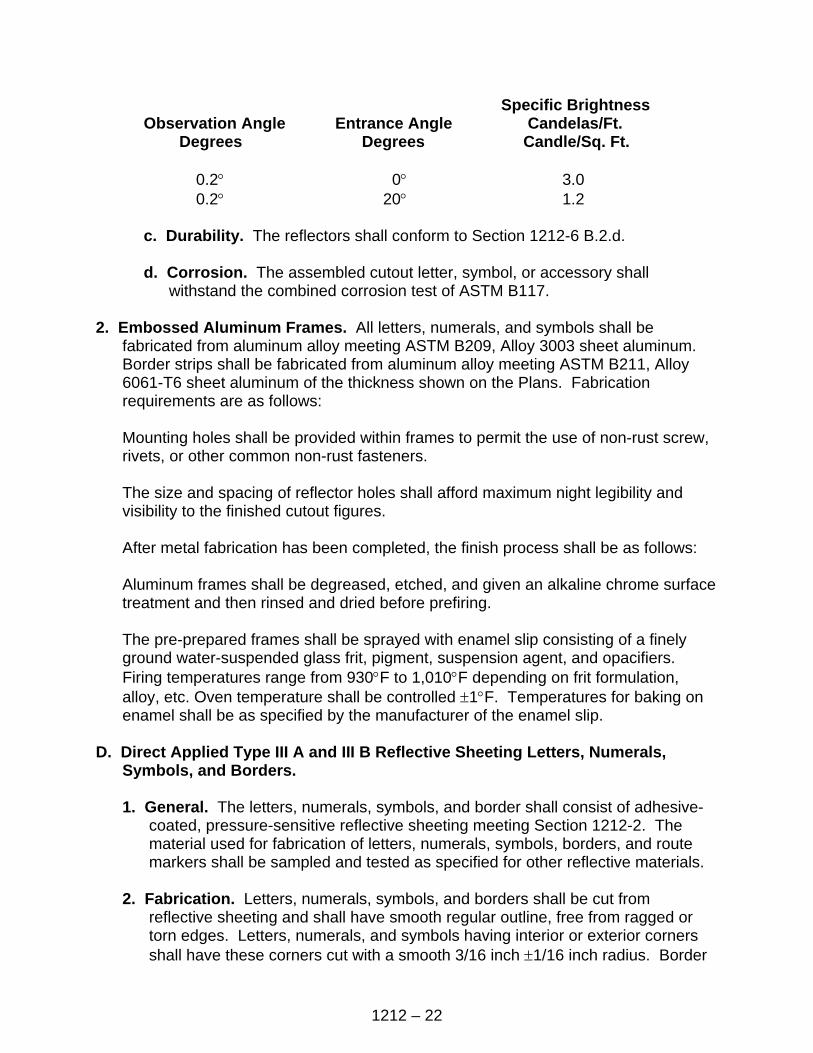
1212 – 22
Specific Brightness Observation Angle Entrance Angle Candelas/Ft. Degrees Degrees Candle/Sq. Ft.
0.2° 0° 3.0 0.2° 20° 1.2
c. Durability. The reflectors shall conform to Section 1212-6 B.2.d.
d. Corrosion. The assembled cutout letter, symbol, or accessory shall
withstand the combined corrosion test of ASTM B117. 2. Embossed Aluminum Frames. All letters, numerals, and symbols shall be
fabricated from aluminum alloy meeting ASTM B209, Alloy 3003 sheet aluminum. Border strips shall be fabricated from aluminum alloy meeting ASTM B211, Alloy 6061-T6 sheet aluminum of the thickness shown on the Plans. Fabrication requirements are as follows:
Mounting holes shall be provided within frames to permit the use of non-rust screw, rivets, or other common non-rust fasteners.
The size and spacing of reflector holes shall afford maximum night legibility and visibility to the finished cutout figures.
After metal fabrication has been completed, the finish process shall be as follows:
Aluminum frames shall be degreased, etched, and given an alkaline chrome surface treatment and then rinsed and dried before prefiring.
The pre-prepared frames shall be sprayed with enamel slip consisting of a finely ground water-suspended glass frit, pigment, suspension agent, and opacifiers. Firing temperatures range from 930°F to 1,010°F depending on frit formulation, alloy, etc. Oven temperature shall be controlled ±1°F. Temperatures for baking on enamel shall be as specified by the manufacturer of the enamel slip.
D. Direct Applied Type III A and III B Reflective Sheeting Letters, Numerals,
Symbols, and Borders.
1. General. The letters, numerals, symbols, and border shall consist of adhesive-coated, pressure-sensitive reflective sheeting meeting Section 1212-2. The material used for fabrication of letters, numerals, symbols, borders, and route markers shall be sampled and tested as specified for other reflective materials.
2. Fabrication. Letters, numerals, symbols, and borders shall be cut from
reflective sheeting and shall have smooth regular outline, free from ragged or torn edges. Letters, numerals, and symbols having interior or exterior corners shall have these corners cut with a smooth 3/16 inch ±1/16 inch radius. Border
1212 – 23
corners and strips shall have no corner radius. Route markers used in conjunction with direct-applied letter shall be applied to 0.040 aluminum backing and shall be attached with blind rivets or other common non-rust fasteners. Fasteners shall be placed a maximum of 6 inches on center around the perimeter of the shield. The reflective sheeting shall be of the same type specified for the letters. All sheeting, numerals, symbols, and borders shall show careful workmanship and shall be of regular outline.
1212-9 POSTS AND HARDWARE FOR SIGNS A. Hardware for Signs.
1. General. All aluminum bolts, nuts, U-bolts, lock washers, and washers shall be given at least a 0.002-inch anodic coating and chromate seal. All steel bolts, nuts, U-bolts, lock washers, and washers shall be galvanized steel meeting ASTM A153.
Use of substitute alloys in lieu of the alloy specified for various items of “Hardware for Signs” may be approved by the ENGINEER upon submission of documented evidence that the proposed substitute alloy has applicable qualities equal to or superior to the designated alloy.
2. Bolts. Aluminum panel bolts, etc., shall be fabricated of aluminum alloy meeting
ASTM B211, Alloy 2024-T4 or 6061-T6.
Steel panel bolts, machine bolts, etc., shall meet ASTM A307.
3. Nuts. Aluminum nuts, hex nuts, vandal-resistant nuts shall be fabricated of aluminum alloy meeting ASTM B211, Alloy 6061-T6.
Steel hex nuts shall meet ASTM A307.
In lieu of using torque wrenches to obtain the required torques for fuse joints and slip base used in the breakaway system, the Torque Control Nut System may be used. This system shall provide automatic torque control, consistently-controlled preload, vibration resistance, high strength, easy installation, simple inspection, and resistance to weather effects.
The torque control nut shall be designed to mate with standard high-strength bolts meeting ASTM A325. The minimum stripping strength of the threads shall be equal to or shall exceed the strength level of the mating bolts.
The self-locking quality of resistance to loosening shall meet the tests in Federal Specification MIL-N-25027 and shall be installed according to the manufacturer’s recommendations.
1212 – 24
4. Washers. Aluminum lock washers shall be fabricated of aluminum alloy meeting ASTM B209, Alloy 7075-T6.
Aluminum flat washers shall be fabricated of aluminum alloy meeting ASTM B209, Alloy 2024-T4.
Steel lock washers shall be fabricated of steel meeting ANSI B27.1.
Steel flat washers shall be fabricated of steel meeting ASTM A307.
Plastic washers shall be fabricated to the sheeting manufacturer’s specifications.
5. Stringers. Aluminum stringers shall be fabricated to Plan dimensions and made
of aluminum alloy meeting ASTM B221, Alloy 6061-T6 or ASTM B308, Alloy 6061-T6.
Steel stringers shall be fabricated to Plan dimensions and made of steel meeting ASTM A36.
6. Aluminum Alloy Castings. Brackets, post caps, and fuse plates may be either
permanent mold castings or sand castings.
Aluminum alloy permanent mold castings shall meet ASTM B108, Alloy SG70A-F or SG80A-T6.
Aluminum alloy sand castings shall meet ASTM B26, Alloy SG70A-F or SG70A-T6.
7. Steel Castings. Brackets, post caps, and fuse plates shall meet AASHTO
M103, Grade 65-35.
8. U-Bolts. Aluminum U-bolts shall be fabricated of aluminum alloy meeting ASTM B211, Alloy 2017-T4.
Steel U-bolts shall be fabricated of steel meeting ASTM A307.
9. Anchor Bolts. Anchor bolts, anchor studs, nuts, and washers shall be
fabricated of steel meeting ASTM A307.
All nuts, washers, and anchor studs shall be galvanized steel meeting ASTM A153.
The hex bar shall be tapped with U.S. Steel. Standard right thread, both ends, and made of steel meeting ASTM A307.
1212 – 25
10. Attachment Clip and Plate. Attachment clip and plate for attachment of steel panels shall be fabricated as shown in the Contract, and made of steel meeting ASTM A283 and galvanized in conformance to ASTM A153.
11. Fuse Joint Bolts. Aluminum fuse plate bolts and washers shall be fabricated
from aluminum meeting ASTM B211, Alloy 2024-T4.
Steel fuse plate bolts and washers shall be fabricated from steel meeting ASTM A325, and nuts shall be of the capacity to develop the bolt strength. Bolts, nuts, and washers shall be galvanized according to ASTM A153.
12. Breakaway Base Bolts. All breakaway base bolts shall have bolts and washers
fabricated from steel meeting ASTM A325, and nuts shall be of the capacity to develop the bolt strength. Bolts, nuts, and washers shall be galvanized according to ASTM A153.
B. Posts.
1. General. Tubular post size, length, and weight shall be as shown in the Contract for each type of sign.
Welding on aluminum shall be done according to Section 5 and welding on galvanized steel shall be done according to Section 4 of the AASHTO Standard Specifications for Structural Supports for Highway Signs, Luminaires, and Traffic Signals.
All markings on posts, signs, casting, etc., shall be removed after erection.
2. Aluminum Tubular Posts and Accessories.
Material Specification Drawn Seamless Tubes and ASTM B210, Alloy 6061-T6 or Extruded Round or Square Tubes ASTM B241, Alloy 6061-T6 Extruded Structural Shapes ASTM B221, alloy 6061-T6 Breakaway Bases ASTM B209, Alloy 6061-T6 Fuse Plates ASTM B209. Alloy 6061-T6 Fuse Plate Bolts and Washers ASTM B211, Alloy 2024-T6
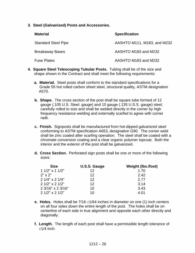
1212 – 26
3. Steel (Galvanized) Posts and Accessories.
Material Specification
Standard Steel Pipe AASHTO M111, M183, and M232
Breakaway Bases AASHTO M183 and M232
Fuse Plates AASHTO M183 and M232
4. Square Steel Telescoping Tubular Posts. Tubing shall be of the size and shape shown in the Contract and shall meet the following requirements:
a. Material. Steel posts shall conform to the standard specifications for a
Grade 55 hot rolled carbon sheet steel, structural quality, ASTM designation A570.
b. Shape. The cross section of the post shall be square tube formed of 12
gauge (.105 U.S. Steel. gauge) and 10 gauge (.135 U.S.S. gauge) steel, carefully rolled to size and shall be welded directly in the corner by high frequency resistance welding and externally scarfed to agree with corner radii.
c. Finish. Signposts shall be manufactured from hot-dipped galvanized steel
conforming to ASTM specification A653, designation G90. The corner weld shall be zinc coated after scarfing operation. The steel shall be coated with a chromate conversion coating and a clear organic polymer topcoat. Both the interior and the exterior of the post shall be galvanized.
d. Cross Section. Perforated sign posts shall be one or more of the following
sizes: Size U.S.S. Gauge Weight (lbs./foot) 1 1/2" x 1 1/2" 12 1.70
2" x 2" 12 2.42 2 1/4" x 2 1/4" 12 2.77 2 1/2" x 2 1/2" 12 3.14 2 3/16" x 2 3/16" 10 3.43 2 1/2" x 2 1/2" 10 4.01
e. Holes. Holes shall be 7/16 ±1/64 inches in diameter on one (1) inch centers
on all four sides down the entire length of the post. The holes shall be on centerline of each side in true alignment and opposite each other directly and diagonally.
f. Length. The length of each post shall have a permissible length tolerance of
±1/4 inch.
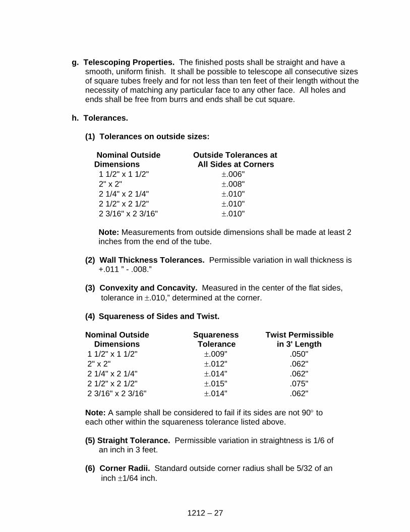
1212 – 27
g. Telescoping Properties. The finished posts shall be straight and have a
smooth, uniform finish. It shall be possible to telescope all consecutive sizes of square tubes freely and for not less than ten feet of their length without the necessity of matching any particular face to any other face. All holes and ends shall be free from burrs and ends shall be cut square.
h. Tolerances.
(1) Tolerances on outside sizes:
Nominal Outside Outside Tolerances at
Dimensions All Sides at Corners 1 1/2" x 1 1/2" ±.006"
2" x 2" ±.008" 2 1/4" x 2 1/4" ±.010" 2 1/2" x 2 1/2" ±.010" 2 3/16" x 2 3/16" ±.010"
Note: Measurements from outside dimensions shall be made at least 2 inches from the end of the tube.
(2) Wall Thickness Tolerances. Permissible variation in wall thickness is
+.011 ” - .008.”
(3) Convexity and Concavity. Measured in the center of the flat sides, tolerance in ±.010,” determined at the corner.
(4) Squareness of Sides and Twist. Nominal Outside Squareness Twist Permissible Dimensions Tolerance in 3' Length
1 1/2" x 1 1/2" ±.009" .050" 2" x 2" ±.012" .062" 2 1/4" x 2 1/4" ±.014" .062" 2 1/2" x 2 1/2" ±.015" .075" 2 3/16" x 2 3/16" ±.014" .062"
Note: A sample shall be considered to fail if its sides are not 90° to each other within the squareness tolerance listed above.
(5) Straight Tolerance. Permissible variation in straightness is 1/6 of
an inch in 3 feet.
(6) Corner Radii. Standard outside corner radius shall be 5/32 of an inch ±1/64 inch.

1212 – 28
i. Installation. The square end of the post shall not be modified or pointed, but shall be capable of being driven into the ground with the use of an approved driving cap.
j. Slip Base Assembly. The design and the construction of the slip base
assembly shall be as shown on the Plans. The assembly shall be as manufactured by Unistrut Corporation or equal. The manufacturer shall certify that the chemistry, geometry, and mechanical properties are the same as those used in the tests and that the assembly will meet FHWA change-in-volocity requirements.
5. Flange Channel and Accessories. Flange channel shall be of the size and
shape specified and shall meet the following requirements:
a. Anchor Plates. The flange channel and anchor plates shall be rolled from High Strength, Hot-Rolled Steel conforming to ASTM A499, Grade 60, 60,000 psi minimum yield strength and 90,000 psi minimum ultimate strength.
b. Safety Retainer-Spacer Strap. The straps shall be of the size and shape
specified and shall be fabricated from steel meeting AISI 1020.
c. Nuts and Bolts. The bolts shall be the size specified and shall be fabricated from steel meeting ASTM A354, Grade BD, case hardened. The nuts shall meet AASHTO M291, Grade DH, and lockwashers shall be heavy-duty external type. Nuts and bolts shall be cadmium plated ASTM A165, Type 05, except when using clear chromate.
d. Fabrication. The finished post shall be machine straightened and have a
uniform finish, free from defects affecting its strength, durability, or appearance. All holes and sheared ends shall be commercially free from burrs.
Sign posts and stringers shall be punched on the center line with 7/16-inch diameter holes on 1-inch centers for the entire length.
Base posts shall be punched on centerline with a minimum of twelve 7/16-inch diameter holes on 1-inch centers. The first hole shall be 1 inch from the top. The bottom of the post shall be pointed for easy installation.
The sign post, base posts, retainer-spacer, and anchor plates shall be galvanized according to AASHTO M232.
6. Structural Steel Posts. Structural steel posts shall be fabricated from material
conforming to Section 834.01A and shall be galvanized according to Section 854 after fabrication.
1212 – 29
1212-10 DELINEATORS A. Posts. Steel posts shall meet ASTM A702.
Steel posts shall be galvanized according to AASHTO M111 or be aluminum posts fabricated from aluminum alloy meeting ASTM B308, Alloy 6061-T6. Posts shall have holes at 1-inch spacing the entire length of the post.
B. Reflectors.
1. Reflective Sheeting. Type III reflective sheeting for delineators shall be white or yellow adhesive coated, permanently adhered to aluminum or galvanized steel.
The reflective sheeting shall meet Section 1212-2. Backing material shall meet
Section 1212-1.
The finished reflector shall show careful workmanship; be free of burrs, scratches, or damaged reflective sheeting; and have essentially a flat surface.
2. Acrylic Plastic.
a. Metal Parts. The housing shall be .020-inch ASTM B209 3003-H14 or
5052-0 sheet aluminum formed to approximately 3 1/4 inches in diameter and .235 inch in depth to retain the acrylic reflector. The housing shall be provided with 4 embossed circular reinforcement ribs and marked with the manufacturer’s name and part number.
An aluminum grommet with a 3/16-inch inside diameter shall be expanded within the reflector mounting hole.
b. Acrylic Plastic. The reflector shall be an acrylic plastic manufactured
from methyl methacrylate. The reflector shall consist of a clear and transparent plastic face, with a minimum of 7 square inches of reflective area, referred to as the lens. It shall have a heat sealable plastic coated metallic foil back fused to the lens under heat and pressure around the entire perimeter of the lens and the central mounting hole to form a unit permanently sealed against dust, water, and water vapor. The reflector shall be colorless, yellow, or red.
The lens shall consist of a smooth front surface free from projection or indentation other than the central mounting hole and identification with a rear surface bearing a prismatic configuration such that it will provide total internal reflection of light.
c. Optical Requirements. The optical requirements shall be as follows:
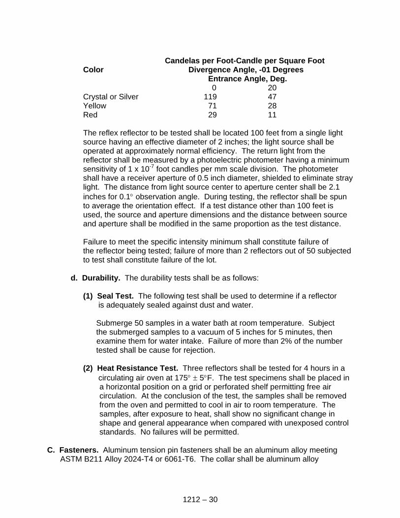
1212 – 30
Candelas per Foot-Candle per Square Foot
Color Divergence Angle, -01 Degrees Entrance Angle, Deg.
0 20 Crystal or Silver 119 47 Yellow 71 28 Red 29 11
The reflex reflector to be tested shall be located 100 feet from a single light source having an effective diameter of 2 inches; the light source shall be operated at approximately normal efficiency. The return light from the reflector shall be measured by a photoelectric photometer having a minimum sensitivity of 1 x 10⁻⁷ foot candles per mm scale division. The photometer shall have a receiver aperture of 0.5 inch diameter, shielded to eliminate stray light. The distance from light source center to aperture center shall be 2.1 inches for 0.1° observation angle. During testing, the reflector shall be spun to average the orientation effect. If a test distance other than 100 feet is used, the source and aperture dimensions and the distance between source and aperture shall be modified in the same proportion as the test distance.
Failure to meet the specific intensity minimum shall constitute failure of the reflector being tested; failure of more than 2 reflectors out of 50 subjected to test shall constitute failure of the lot.
d. Durability. The durability tests shall be as follows:
(1) Seal Test. The following test shall be used to determine if a reflector
is adequately sealed against dust and water.
Submerge 50 samples in a water bath at room temperature. Subject the submerged samples to a vacuum of 5 inches for 5 minutes, then examine them for water intake. Failure of more than 2% of the number tested shall be cause for rejection.
(2) Heat Resistance Test. Three reflectors shall be tested for 4 hours in a
circulating air oven at 175° ± 5°F. The test specimens shall be placed in a horizontal position on a grid or perforated shelf permitting free air circulation. At the conclusion of the test, the samples shall be removed from the oven and permitted to cool in air to room temperature. The samples, after exposure to heat, shall show no significant change in shape and general appearance when compared with unexposed control standards. No failures will be permitted.
C. Fasteners. Aluminum tension pin fasteners shall be an aluminum alloy meeting
ASTM B211 Alloy 2024-T4 or 6061-T6. The collar shall be aluminum alloy
1212 – 31
509.1212-6 C meeting ASTM B211 Alloy 6061-T67 or 6061-T6. The fasteners shall conform to the Contract.
Steel tension pin fasteners shall be a medium carbon steel with a minimum shear strength of 70,000 psi and a minimum tensile strength of 67,500 psi. They shall be galvanized according to AASHTO M232 conforming to the Contract.
1212-11 SAMPLING AND TESTING A. Base Metal. The CONTRACTOR shall furnish to the inspector a certification as
specified in Section 801-1. B. Solutions for Cleaning and Etching. The solutions used for cleaning and etching
shall not vary more than 10% from the manufacturer’s recommendation. In addition, all treatment tanks shall be charged with fresh chemicals at least once a year. Titration equipment shall be available for the inspector ’s use to check the solution strengths.
C. Inspection. All material and finished signs are subject to inspection at the place of
manufacture and shall be subject to final inspection at the time of erection. Test panels, 12 inches by 12 inches representative of any stage of production, shall be furnished upon the inspector’s request. These panels shall be processed with the regular production run and witnessed by the inspector. All surfaces exposed to weathering shall be free of any defects that may impair the serviceability or detract from the general appearance or color matching of the sign. Signs with any defects or damage that would affect their appearance or serviceability will not be accepted. No repairs shall be made to the face sheet without the approval of the inspector. Signs not conforming in all respects to the requirements will be rejected.
D. Reflective Sheeting. The reflective sheeting shall be certified by the manufacturer
that the minimum brightness values previously listed for each color, have been met. The color of each type shall be checked by the inspector using the standard color charts as specified.
1. Reflective Sheeting Flexibility. The CONTRACTOR shall furnish test
specimens for each color of reflective sheeting according to AASHTO M268. Type III and Type IV reflective sheeting shall be applied to a plate as specified in
AASHTO M268 and shall be furnished for each color. These test specimens shall be processed with the regular production run and witnessed by the inspector.
2. Inspection. The reflective sheeting packages shall be inspected before
installation on sign backings. The CONTRACTOR shall provide access by the inspector and shall indicate the roll packages or flat packages to be used on a particular Project. The inspector will mark the roll of flat material and note the manufacturer’s date. All material used on that Project shall be used within one
1212 – 32
year of this date. If this date is past on the date of inspection, the roll shall be rejected.
E. Torque Control Nuts. The CONTRACTOR shall furnish to the inspector a
certification if torque control nuts are chosen for use.