Embed Size (px)
Citation preview
68 IEEE TRANSACTIONS ON ENERGY CONVERSION, VOL. 24, NO. 1, MARCH 2009
Behavior of the Three-Phase Induction Motor WithSpiral Sheet Rotor
Ramon Mujal Rosas, Oriol Boix Aragones, Senior Member, IEEE, Xavier Colom Fajula, and Alejandro Rolan Blanco
Abstract—Improvements in torque at low currents using a rotorwith spiral sheets are analyzed. Several rotors and stators havebeen built combining different constructive and mechanical char-acteristics of the related elements: inertias, constructive materials,geometrical shapes of the sheets, and geometrical disposition ofthe sheets. These different types of motors have been simulatedusing computer-aided tools and then tested in the laboratory. Fi-nally, four stators (1000, 1500, 1500-type A, and 3000 r/min), withthe same constructive parameters, have been simulated and testedwith the following rotors types: solid rotor, solid rotor with diamag-netic rings, drag cup, and simple and double squirrel cage rotor;the results have been compared to those obtained with the sevenvariants of the spiral sheet rotor presented in this paper.
Index Terms—Electric machines, special machine, spiral sheetrotor, three-phase asynchronous motor.
I. INTRODUCTION
THE ROTORS of conventional asynchronous motors areformed by magnetic sheets packed above the shaft of the
machine. The rotating magnetic field created by the stator in-duces currents parallel to the shaft and thus upright to the rotorsheets [1]. These currents cannot flow between the sheets ifthey are electrically isolated, requiring the intervention of con-ventional squirrel cage rings to close the electric circuit so thatthe rotor currents can circulate.
Typical configurations of three-phase asynchronous motors[2] are shown in Fig. 1 and described in the following points.
1) Single cage winding with high resistance and minimalinductance.
2) Deep slot cage, with low resistance and progressive reac-tance with the slip.
3) Low resistance and low reactance slot.4) Finally, there are additional configurations of double and
triple cage combining characteristics of the previous dis-positions, with different resistance and reactance valuesfor each cage.
In all of these dispositions, currents go through the cage con-ductors [3], while magnetic field goes through the sheets. Theperformance of these motors depends on the magnetic field, thecurrent, and the distance from the conductor to the shaft.
Manuscript received December 4, 2007; revised February 6, 2008. Firstpublished January 20, 2009; current version published February 19, 2009. Thiswork was supported by the “Ministerio de Ciencia y Tecnologıa de Espana”under DPI 2004-03180 Research Project. Paper no. TEC-00476-2007.
R. M. Rosas, O. B. Aragones, and A. R. Blanco are with the Department ofElectrical Engineering, Technical University of Catalonia, 08222 Terrassa, Spain(e-mail: [email protected]; [email protected]; [email protected]).
X. C. Fajula is with the Department of Chemical Engineering, Technical Uni-versity of Catalonia, 08222 Terrassa, Spain (e-mail: [email protected]).
Digital Object Identifier 10.1109/TEC.2008.2005283
Fig. 1. Typical configurations of three-phase asynchronous motors.
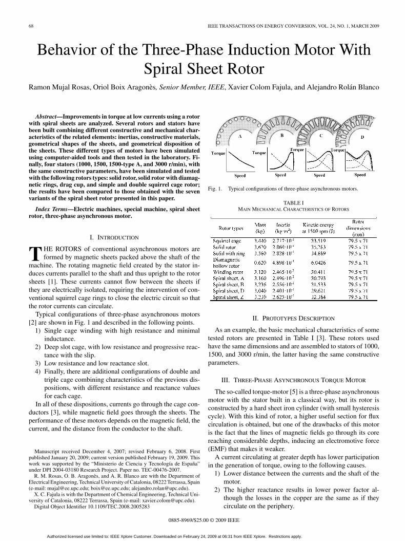
TABLE IMAIN MECHANICAL CHARACTERISTICS OF ROTORS
II. PROTOTYPES DESCRIPTION
As an example, the basic mechanical characteristics of sometested rotors are presented in Table I [3]. These rotors usedhave the same dimensions and are assembled to stators of 1000,1500, and 3000 r/min, the latter having the same constructiveparameters.
III. THREE-PHASE ASYNCHRONOUS TORQUE MOTOR
The so-called torque-motor [5] is a three-phase asynchronousmotor with the stator built in a classical way, but its rotor isconstructed by a hard sheet iron cylinder (with small hysteresiscycle). With this kind of rotor, a higher useful section for fluxcirculation is obtained, but one of the drawbacks of this motoris the fact that the lines of magnetic fields go through its corereaching considerable depths, inducing an electromotive force(EMF) that makes it weaker.
A current circulating at greater depth has lower participationin the generation of torque, owing to the following causes.
1) Lower distance between the currents and the shaft of themotor.
2) The higher reactance results in lower power factor al-though the losses in the copper are the same as if theycirculate on the periphery.
0885-8969/$25.00 © 2009 IEEE
Authorized licensed use limited to: IEEE Xplore Customer. Downloaded on February 24, 2009 at 06:31 from IEEE Xplore. Restrictions apply.
ROSAS et al.: BEHAVIOR OF THE THREE-PHASE INDUCTION MOTOR WITH SPIRAL SHEET ROTOR 69
Fig. 2. Section of a “three-phase asynchronous torque-motor.”
Fig. 3. Rotors: with double cage A. Spiral sheet rotors B and C types.
Fig. 4. Section of a “three-phase asynchronous torque-motor.”
In Fig. 2, this phenomenon is illustrated showing that thedeeper currents are weaker, and also have some delay in thedirection of the displacement.
IV. MOTOR WITH A SPIRAL SHEET ROTOR
Forming a rotor with spiral-shape sheets [8] distributed in aradial disposition around the shaft, it is possible to generate amagnetic field in the rotor periphery, inducing peripheral EMF,and currents along the same sheets, which are only active intheir periphery.
The peripheral currents of this rotor have more section tocirculate, compared to a normal cage rotor current, as can beseen in Fig. 3.
Fig. 4 shows a plain representation of the disposition of thesheets [9]. There are two zones: one with active currents goingthrough and the other is used to receive the possible returningcurrents (a returning currents proposal).
The returning currents can be established in two ways, asshown in Fig. 5.
A) In the construction through short-circuit rings, the resis-tance corresponds to that of the outside of the iron sheetsthat form the rotor. This is because the short-circuit ringcan be built in a big section, and its resistance can bedespised compared to the resistance offered by the su-perficial sheets layers. This solution is not suitable formanufacturing; however, it gives the best results.
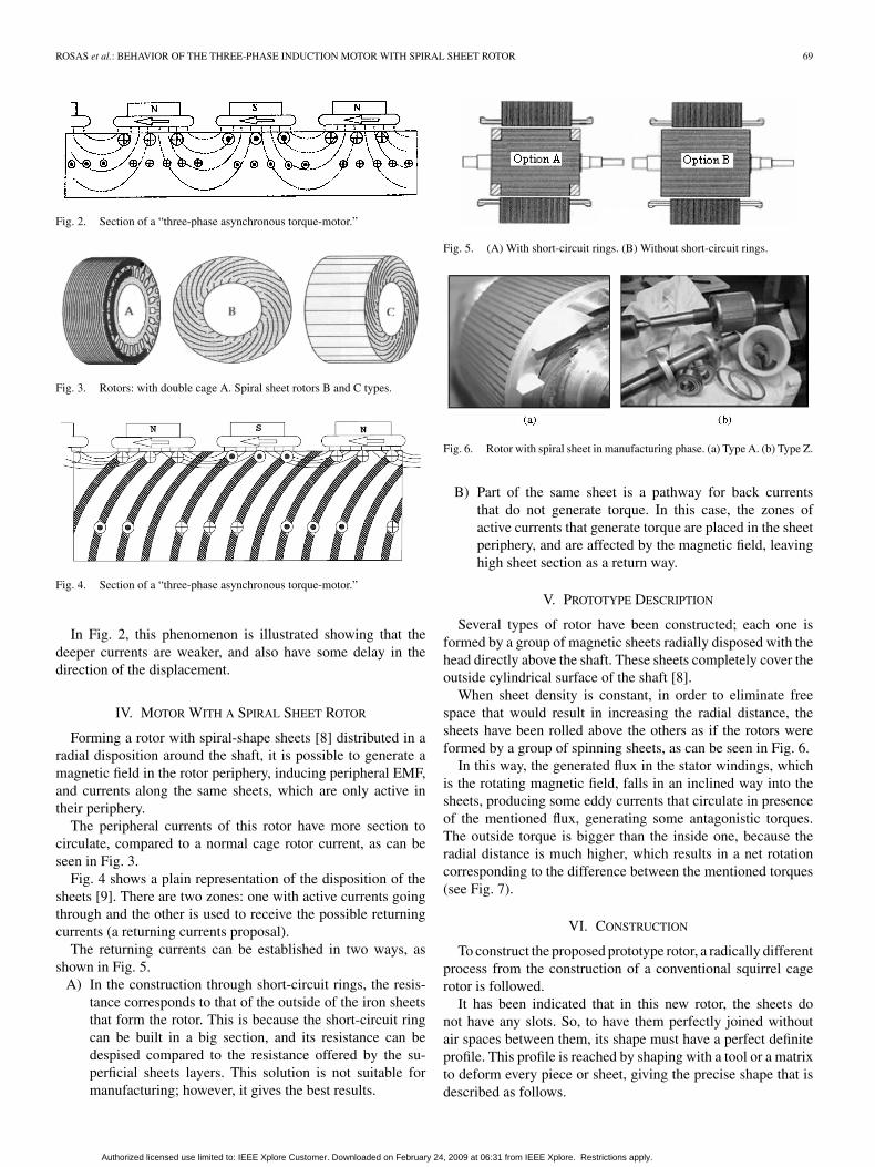
Fig. 5. (A) With short-circuit rings. (B) Without short-circuit rings.
Fig. 6. Rotor with spiral sheet in manufacturing phase. (a) Type A. (b) Type Z.
B) Part of the same sheet is a pathway for back currentsthat do not generate torque. In this case, the zones ofactive currents that generate torque are placed in the sheetperiphery, and are affected by the magnetic field, leavinghigh sheet section as a return way.
V. PROTOTYPE DESCRIPTION
Several types of rotor have been constructed; each one isformed by a group of magnetic sheets radially disposed with thehead directly above the shaft. These sheets completely cover theoutside cylindrical surface of the shaft [8].
When sheet density is constant, in order to eliminate freespace that would result in increasing the radial distance, thesheets have been rolled above the others as if the rotors wereformed by a group of spinning sheets, as can be seen in Fig. 6.
In this way, the generated flux in the stator windings, whichis the rotating magnetic field, falls in an inclined way into thesheets, producing some eddy currents that circulate in presenceof the mentioned flux, generating some antagonistic torques.The outside torque is bigger than the inside one, because theradial distance is much higher, which results in a net rotationcorresponding to the difference between the mentioned torques(see Fig. 7).
VI. CONSTRUCTION
To construct the proposed prototype rotor, a radically differentprocess from the construction of a conventional squirrel cagerotor is followed.
It has been indicated that in this new rotor, the sheets donot have any slots. So, to have them perfectly joined withoutair spaces between them, its shape must have a perfect definiteprofile. This profile is reached by shaping with a tool or a matrixto deform every piece or sheet, giving the precise shape that isdescribed as follows.
Authorized licensed use limited to: IEEE Xplore Customer. Downloaded on February 24, 2009 at 06:31 from IEEE Xplore. Restrictions apply.
70 IEEE TRANSACTIONS ON ENERGY CONVERSION, VOL. 24, NO. 1, MARCH 2009
Fig. 7. Rotating magnetic field, eddy currents, and antagonistic torques.
Fig. 8. Trigonometric relations of the sheet rotor.
If a rotor of interior radius R is considered, formed by n sheetsof thickness e, where this thickness is very small compared toR, and with an outside radius RE , then the trigonometric ratiosshown in Fig. 8 are obtained.
A. Calculus of Length of the Sheet as a Function of the InteriorRadius R and the Exterior Radius RE
If the perimeter of the sheets is equal and grows with insideradius R and outside radius RE , then
2πR = en 2πρ =en
cos α
R
ρ= cos α. (1)
Also, from the differential triangle, knowing that both anglesα are the same because of the perpendicular sides, then
dl =dρ
cos αor dl =
ρdρ
R(2)
and by integrating
[L] =[
ρ2
2R
]RE
R
and L =
(R2
E − R2)
2R. (3)
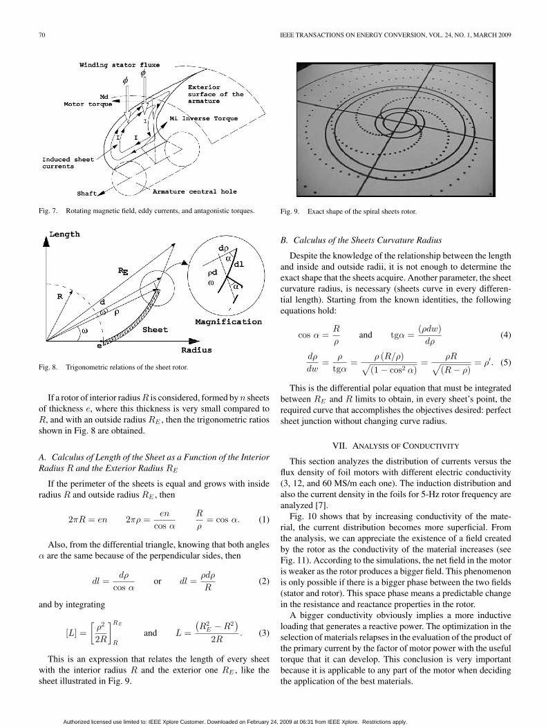
This is an expression that relates the length of every sheetwith the interior radius R and the exterior one RE , like thesheet illustrated in Fig. 9.
Fig. 9. Exact shape of the spiral sheets rotor.
B. Calculus of the Sheets Curvature Radius
Despite the knowledge of the relationship between the lengthand inside and outside radii, it is not enough to determine theexact shape that the sheets acquire. Another parameter, the sheetcurvature radius, is necessary (sheets curve in every differen-tial length). Starting from the known identities, the followingequations hold:
cos α =R
ρand tgα =
(ρdw)dρ
(4)
dρ
dw=
ρ
tgα=
ρ (R/ρ)√(1 − cos2 α)
=ρR√
(R − ρ)= ρ′. (5)
This is the differential polar equation that must be integratedbetween RE and R limits to obtain, in every sheet’s point, therequired curve that accomplishes the objectives desired: perfectsheet junction without changing curve radius.
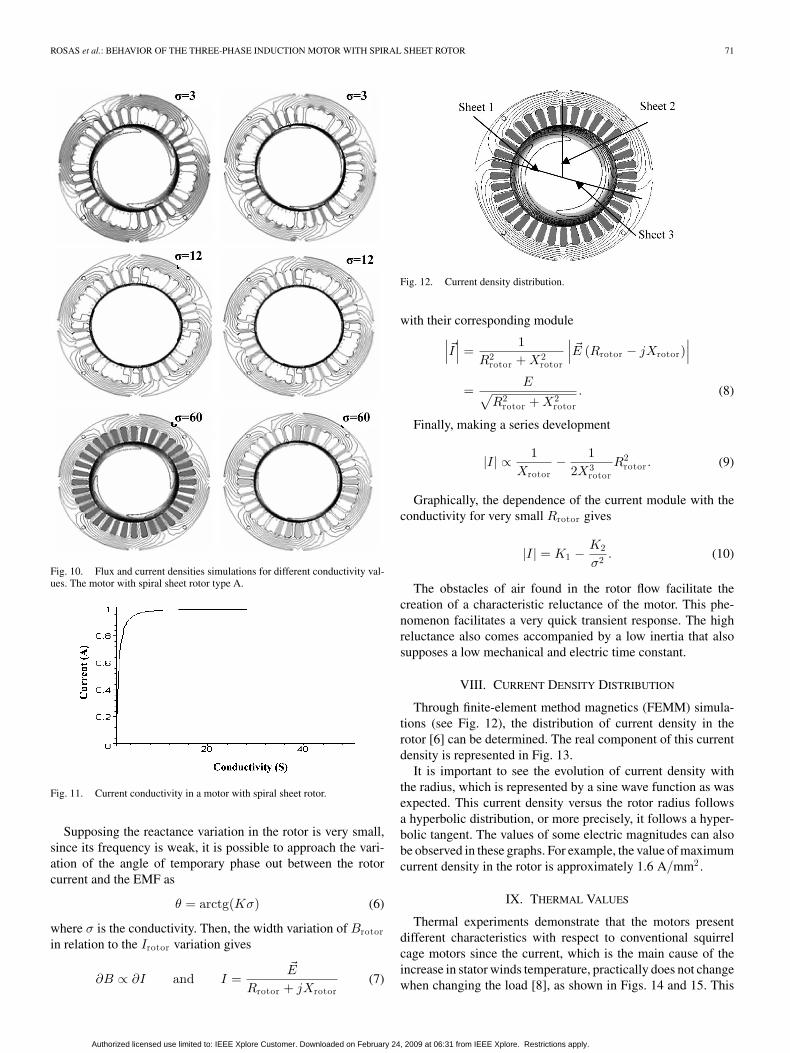
VII. ANALYSIS OF CONDUCTIVITY
This section analyzes the distribution of currents versus theflux density of foil motors with different electric conductivity(3, 12, and 60 MS/m each one). The induction distribution andalso the current density in the foils for 5-Hz rotor frequency areanalyzed [7].
Fig. 10 shows that by increasing conductivity of the mate-rial, the current distribution becomes more superficial. Fromthe analysis, we can appreciate the existence of a field createdby the rotor as the conductivity of the material increases (seeFig. 11). According to the simulations, the net field in the motoris weaker as the rotor produces a bigger field. This phenomenonis only possible if there is a bigger phase between the two fields(stator and rotor). This space phase means a predictable changein the resistance and reactance properties in the rotor.
A bigger conductivity obviously implies a more inductiveloading that generates a reactive power. The optimization in theselection of materials relapses in the evaluation of the product ofthe primary current by the factor of motor power with the usefultorque that it can develop. This conclusion is very importantbecause it is applicable to any part of the motor when decidingthe application of the best materials.
Authorized licensed use limited to: IEEE Xplore Customer. Downloaded on February 24, 2009 at 06:31 from IEEE Xplore. Restrictions apply.
ROSAS et al.: BEHAVIOR OF THE THREE-PHASE INDUCTION MOTOR WITH SPIRAL SHEET ROTOR 71
Fig. 10. Flux and current densities simulations for different conductivity val-ues. The motor with spiral sheet rotor type A.
Fig. 11. Current conductivity in a motor with spiral sheet rotor.
Supposing the reactance variation in the rotor is very small,since its frequency is weak, it is possible to approach the vari-ation of the angle of temporary phase out between the rotorcurrent and the EMF as
θ = arctg(Kσ) (6)
where σ is the conductivity. Then, the width variation of Brotorin relation to the Irotor variation gives
∂B ∝ ∂I and I =�E
Rrotor + jXrotor(7)
Fig. 12. Current density distribution.
with their corresponding module∣∣∣�I∣∣∣ =
1R2
rotor + X2rotor
∣∣∣ �E (Rrotor − jXrotor)∣∣∣
=E√
R2rotor + X2
rotor
. (8)
Finally, making a series development
|I| ∝ 1Xrotor
− 12X3
rotorR2
rotor . (9)
Graphically, the dependence of the current module with theconductivity for very small Rrotor gives
|I| = K1 −K2
σ2 . (10)
The obstacles of air found in the rotor flow facilitate thecreation of a characteristic reluctance of the motor. This phe-nomenon facilitates a very quick transient response. The highreluctance also comes accompanied by a low inertia that alsosupposes a low mechanical and electric time constant.
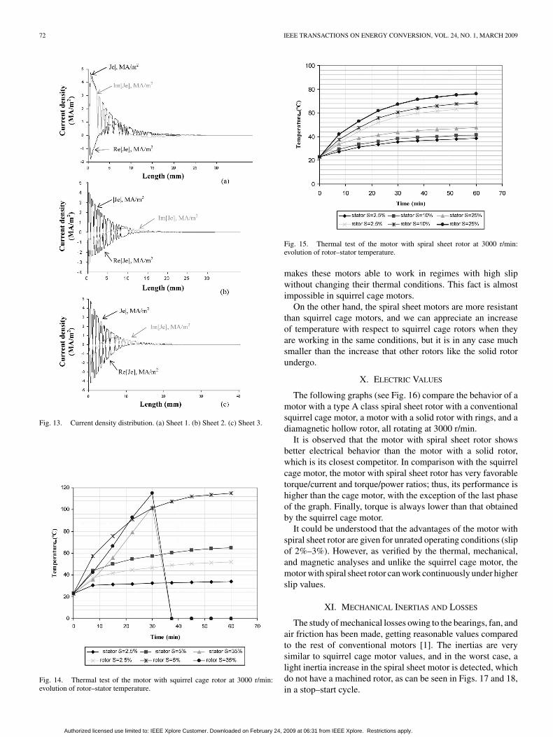
VIII. CURRENT DENSITY DISTRIBUTION
Through finite-element method magnetics (FEMM) simula-tions (see Fig. 12), the distribution of current density in therotor [6] can be determined. The real component of this currentdensity is represented in Fig. 13.
It is important to see the evolution of current density withthe radius, which is represented by a sine wave function as wasexpected. This current density versus the rotor radius followsa hyperbolic distribution, or more precisely, it follows a hyper-bolic tangent. The values of some electric magnitudes can alsobe observed in these graphs. For example, the value of maximumcurrent density in the rotor is approximately 1.6 A/mm2 .
IX. THERMAL VALUES
Thermal experiments demonstrate that the motors presentdifferent characteristics with respect to conventional squirrelcage motors since the current, which is the main cause of theincrease in stator winds temperature, practically does not changewhen changing the load [8], as shown in Figs. 14 and 15. This
Authorized licensed use limited to: IEEE Xplore Customer. Downloaded on February 24, 2009 at 06:31 from IEEE Xplore. Restrictions apply.
72 IEEE TRANSACTIONS ON ENERGY CONVERSION, VOL. 24, NO. 1, MARCH 2009
Fig. 13. Current density distribution. (a) Sheet 1. (b) Sheet 2. (c) Sheet 3.
Fig. 14. Thermal test of the motor with squirrel cage rotor at 3000 r/min:evolution of rotor–stator temperature.
Fig. 15. Thermal test of the motor with spiral sheet rotor at 3000 r/min:evolution of rotor–stator temperature.
makes these motors able to work in regimes with high slipwithout changing their thermal conditions. This fact is almostimpossible in squirrel cage motors.
On the other hand, the spiral sheet motors are more resistantthan squirrel cage motors, and we can appreciate an increaseof temperature with respect to squirrel cage rotors when theyare working in the same conditions, but it is in any case muchsmaller than the increase that other rotors like the solid rotorundergo.
X. ELECTRIC VALUES
The following graphs (see Fig. 16) compare the behavior of amotor with a type A class spiral sheet rotor with a conventionalsquirrel cage motor, a motor with a solid rotor with rings, and adiamagnetic hollow rotor, all rotating at 3000 r/min.
It is observed that the motor with spiral sheet rotor showsbetter electrical behavior than the motor with a solid rotor,which is its closest competitor. In comparison with the squirrelcage motor, the motor with spiral sheet rotor has very favorabletorque/current and torque/power ratios; thus, its performance ishigher than the cage motor, with the exception of the last phaseof the graph. Finally, torque is always lower than that obtainedby the squirrel cage motor.
It could be understood that the advantages of the motor withspiral sheet rotor are given for unrated operating conditions (slipof 2%–3%). However, as verified by the thermal, mechanical,and magnetic analyses and unlike the squirrel cage motor, themotor with spiral sheet rotor can work continuously under higherslip values.
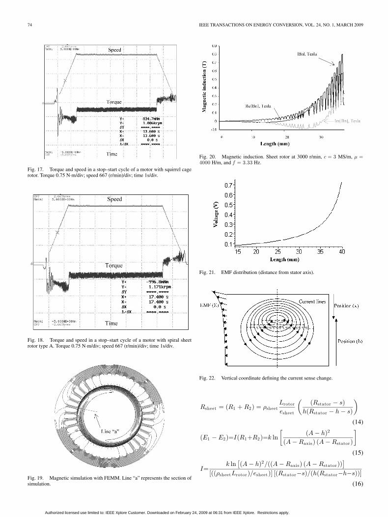
XI. MECHANICAL INERTIAS AND LOSSES
The study of mechanical losses owing to the bearings, fan, andair friction has been made, getting reasonable values comparedto the rest of conventional motors [1]. The inertias are verysimilar to squirrel cage motor values, and in the worst case, alight inertia increase in the spiral sheet motor is detected, whichdo not have a machined rotor, as can be seen in Figs. 17 and 18,in a stop–start cycle.
Authorized licensed use limited to: IEEE Xplore Customer. Downloaded on February 24, 2009 at 06:31 from IEEE Xplore. Restrictions apply.

ROSAS et al.: BEHAVIOR OF THE THREE-PHASE INDUCTION MOTOR WITH SPIRAL SHEET ROTOR 73
Fig. 16. Experimental results using different types of rotors (at 3000 r/min).
Finally, the experiments done to test mechanical resistancein long-term operation were satisfactory because although theserotors were not designed for periods of prolonged operations,they have not undergone any type of deformation.
XII. PARASITIC CURRENTS
Using simulation and a normal section test, it is possible toknow the induction in a rotor (see Figs. 19 and 20).
With this distribution, the EMF results
E = −∂φ
∂t= −∂B
∂tS = −SBwS cos wS t (11)
where S is the magnetic circuit area, a constant in this case.
The current induced by this EMF in sheets can be calcu-lated using the respective electric circuits, remembering thatcurrent flows inside the sheets. The EMF distribution is shown inFig. 21.
This distribution is owing to the EMF in the upper area ofthe sheets inducing a higher current in this section (see Fig. 22).The maximum current can be calculated (r is the height of thesheets from the rotor axis center)
∣∣E1∣∣ =
∫ h
Ra x i s
k
(A − r)dr = k ln
A − Raxis
A − h(12)
∣∣E2∣∣ =
∫ R s t a t o r
h
k
(A − r)dr = k ln
A − h
A − Rstator(13)
Authorized licensed use limited to: IEEE Xplore Customer. Downloaded on February 24, 2009 at 06:31 from IEEE Xplore. Restrictions apply.
74 IEEE TRANSACTIONS ON ENERGY CONVERSION, VOL. 24, NO. 1, MARCH 2009
Fig. 17. Torque and speed in a stop–start cycle of a motor with squirrel cagerotor. Torque 0.75 N·m/div; speed 667 (r/min)/div; time 1s/div.
Fig. 18. Torque and speed in a stop–start cycle of a motor with spiral sheetrotor type A. Torque 0.75 N·m/div; speed 667 (r/min)/div; time 1s/div.
Fig. 19. Magnetic simulation with FEMM. Line “a” represents the section ofsimulation.
Fig. 20. Magnetic induction. Sheet rotor at 3000 r/min, c = 3 MS/m, µ =4000 H/m, and f = 3.33 Hz.
Fig. 21. EMF distribution (distance from stator axis).
Fig. 22. Vertical coordinate defining the current sense change.
Rsheet = (R1 + R2) = ρsheetLrotor
esheet
((Rstator − s)
h(Rstator − h − s)
)
(14)
(E1 − E2)=I(R1+R2)=k ln[
(A − h)2
(A − Raxis) (A − Rstator)
]
(15)
I=k ln
[(A − h)2/((A − Raxis) (A − Rstator))
][((ρsheetLrotor)/esheet)] [(Rstator−s)/(h(Rstator−h−s))]
(16)
Authorized licensed use limited to: IEEE Xplore Customer. Downloaded on February 24, 2009 at 06:31 from IEEE Xplore. Restrictions apply.

ROSAS et al.: BEHAVIOR OF THE THREE-PHASE INDUCTION MOTOR WITH SPIRAL SHEET ROTOR 75
Fig. 23. Distribution of the active current along the radial sheet of the rotor.
where the constants A and k are values that adjust the elec-tromagnetic field equation; s is a parameter that depends uponthe current circulating through the upper sheet area; h is thesheet radius; eaxis is the sheet thickness (in millimeters); σ isthe sheet conductivity (in siemens meter per square millimeter);Lrotor isthe rotor length.
As the induction is a function of the radial position of theconsidered section, which is known, it is possible to calculatethe constants A and K
Bmax =K
(A − Rstator)A =
BminRrotor − RstatorBmax
Bmin − Bmax
(17)
Bmin =K
(A − Rrotor)K = Bmin(A − Rrotor) (18)
and k is a constant function of maximum EMF
E =k
(A − r)k = Emax −2(A − Rstator) (19)
Emax −2 = Emax −1
(m1
m2
)(Z2ξ2
Z1ξ1
)(20)
where m1 and m2 are the number of phases of the stator androtor; Z1 and Z2 are the number of turns and sheets of the statorand rotor; ξ1 and ξ2 are the distribution factors for the statorand rotor.
All the terms are known except the radial coordinate h thatcorresponds to a change of sense in the current along the shapeprofile.
With the coordinate h known, it is possible to calculate the to-tal sheet current, by integration of the current equation betweenthe upper and lower limits of the sheet (the distribution of theactive current along the radial sheet is shown in Fig. 23)
Iupper =∫ R s t a t o r
h
[(kesheet
ρsheetLrotor
)ln
[(A−h)2
(A−Raxis) (A−Rstator)
]
×[h(Rstator − h − s)
(Rstator − s)
]]dh (21)
Ilower =∫ h
R r o t o r
[(kesheet
ρsheetLrotor
)ln
[(A − h)2
(A−Raxis) (A − Rstator)
]
×[h(Rstator − h − s)
(Rstator − s)
]]dh (22)
The ring per sheet current and the total currents are
Iring per sheet = Iupper − Ilower (23)
Itotal ring =Iring per sheet
2p× nrotor sheets
π. (24)
The torque is related to this total current
τ =∫ R s t a t o r
R r o t o r
LrotorB(r)I(r)dh
= Lrotor
∫ R s t a t o r
R r o t o r
[(K
(A − h)
) (kesheet
ρsheetLrotor
)
× ln[
(A − h)2
(A−Raxis) (A−Rstator)
]((h(Rstator−h−s)
(Rstator−s)
)]dh.
(25)
XIII. CONCLUSION
The three-phase induction motor with spiral sheet rotor estab-lishes several advantages in relation to conventional inductionmotors, namely, high starting torque with limited starting cur-rent, small current variations against load changes, moderatedlevel of no-load power losses, acceptable efficiency in steadystate, and good transient response.
The aforementioned performances make the proposed motorsuitable for high-speed applications with frequent stops andstarts, which means, in addition to a good electrical response,this motor should be characterized by good thermal behaviorand high constructive robustness to withstand frequent speedvariations.
A notable disadvantage is the high construction cost of theproposed motor compared to a conventional induction motor.This is mainly owing to the specialized tools used for mecha-nizing the sheets of the rotor and their sophisticated assembly.For this reason, this motor should be produced in large manu-facturing lots.
Nowadays, a wide scope of applications exists requiring theaforementioned characteristics, notably, small staple fiber mo-tors used in textile industries, drives for household appliances,machine tools, etc. Therefore, a widespread market could beexpected for the proposed motor.
REFERENCES
[1] X. Li, Q. Wu, and S. Nandi, “Performance analysis of a three-phaseinduction machine with inclined static eccentricity,” IEEE Trans. Ind.Appl., vol. 43, no. 2, pp. 531–541, Mar./Apr. 2007.
[2] D. Gonen, “Analysis of a 2-phase drag-cup induction machine,” IEEETrans. Power App. Syst., vol. 85, no. 1, pp. 71–76, Jan. 1966.
[3] J. F. Lindsay and T. H. Barton, “Parameter identification for squirrelcage induction machines,” IEEE Trans. Power App. Syst., vol. 92, no. 1,pp. 1287–1291, Jan. 1996.
Authorized licensed use limited to: IEEE Xplore Customer. Downloaded on February 24, 2009 at 06:31 from IEEE Xplore. Restrictions apply.

76 IEEE TRANSACTIONS ON ENERGY CONVERSION, VOL. 24, NO. 1, MARCH 2009
[4] R. Mujal and L. Humet, “Asynchronous motor with spiral sheet rotor,” inProc. ICEM 2000, Helsinki, Finland, Aug. 28–30, pp. 477–482.
[5] R. Mujal, “Asynchronous motor with spiral sheet rotor. Improvementof the functional characteristics of the asynchronous motors,” in Proc.ICEMS 2001, Shenyang, China, Aug. 18–20, pp. 80–84.
[6] R. Mujal, “Three-phase asynchronous motor with spiral sheet rotor. Per-formance improvement of the three-phase induction motors,” presented atthe ISC 2002, Tsukuba, Japan, Aug. 26–28.
[7] R. Mujal, “Three-phase asynchronous motor with spiral sheet rotor. Ma-terial effects and analysis,” in Proc. IEEE Int. Electr. Mach. Drives Conf.,Madison, USA, Mar. 1–4, 2003, pp. 1688–1694.
[8] R. Mujal, “Electromagnetic analysis of the induction motor with spiralsheet rotor,” presented at the EPE 2005, Dresden, Germany, Sep. 12–15.
[9] R. Mujal, “Analysis of the induction motor with spiral sheet rotor,”presented at the ICEM 2006, Crete, Greece, Sep. 4–6.
[10] R. Mujal and O. Boix, “Improvements of three phase induction motor withspiral sheet rotor,” in Proc. IEEE Int. Symp. Ind. Electron. ISIE 2007, Vigo,Spain, Jun. 4–7, pp. 1107–1112.
Ramon Mujal Rosas was born in Cardona, Spain. He received the B.S.degree in electrical engineering and the Ph.D. degree in electrical engineeringfrom the Technical University of Catalonia, Terrassa, Spain, in 1993 and 2004,respectively.
He is a currently a Professor in the Department of Electrical Engineering,Technical University of Catalonia. He is the author or coauthor of some booksabout electrical subjects, and is engaged in the areas of remote learning andspecial electrical machines.
Oriol Boix Aragones (M’00–SM’06) was born in Barcelona, Spain. He receivedthe B.S. degree in electrical engineering and the Ph.D. degree in electrical en-gineering from the Technical University of Catalonia, Terrassa, Spain, in 1988and 1997, respectively.
He is a currently a Professor in the Department of Electrical Engineer-ing, Technical University of Catalonia. His current research interests includeInternet-based learning, harmonics, and power quality areas.
Xavier Colom Fajula was born in Sant Joan de les Abadesses, Spain. Hereceived the B.S. degree in chemical engineering and the Ph.D. degree in materialscience from the Technical University of Catalonia, Terrassa, Spain, in 1991 and1997, respectively.
He is a currently a Professor in the Department of Chemical Engineering,Technical University of Catalonia. He is the author or coauthor of several papersabout polymer and composite materials, some books about material sciencesubjects, and a referee of various journals.
Alejandro Rolan Blanco was born in Sabadell, Spain. He received the B.S.degree in electrical engineering in 2007 from the Technical University of Cat-alonia, Terrassa, Spain, where he is currently working toward the Doctoratedegree in electrical engineering.
Since September 2007, he has been an Associate Professor in the Departmentof Electrical Engineering, Technical University of Catalonia.
Authorized licensed use limited to: IEEE Xplore Customer. Downloaded on February 24, 2009 at 06:31 from IEEE Xplore. Restrictions apply.


![Title 68 RCW - Washington State · 2016. 9. 23. · (2016 Ed.) [Title 68 RCW—page 1] Title 68 Title 68 68 CEMETERIES, MORGUES, AND HUMAN REMAINSCEMETERIES, MORGUES, AND HUMAN REMAINS](https://img.pdfslide.us/doc/110x75/60aab8bfaf00663cd7475042/title-68-rcw-washington-state-2016-9-23-2016-ed-title-68-rcwapage-1.jpg)


![1 Introduction (68) [Compatibility Mode] 21-68](https://img.pdfslide.us/doc/110x75/577c81c51a28abe054ae0be4/1-introduction-68-compatibility-mode-21-68.jpg)