Embed Size (px)
Citation preview
1 DDisplay isplay DDevice evice LLabab Dong-A UniversityDong-A University
Optical compensation design of Optical compensation design of
vertically aligned LC cell using wide view vertically aligned LC cell using wide view
circular polarizercircular polarizer
Je-Wook Moon, Byung-June Mun, Dong-Eon Lim and Gi-Dong Lee
Department of Electronics Engineering, Dong-A University, Busan 604-714, Korea
2 DDisplay isplay DDevice evice LLabab Dong-A UniversityDong-A University
▷ What are required for LCD applications ?
▷ Light leakage of the conventional circular polarizer
in oblique direction
▷ Optical Design on the Poincaré sphere
▷ Calculation results
▷ Conclusion
Outline
3 DDisplay isplay DDevice evice LLabab Dong-A UniversityDong-A University
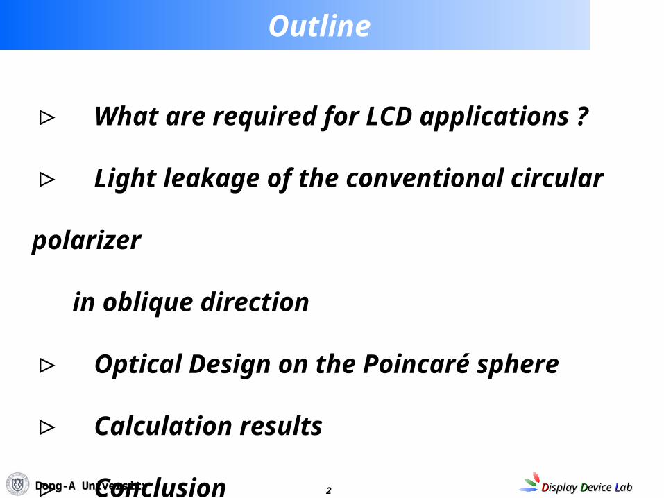
Ⅰ. What are required for LCD applications ?
High Brightness
Wide Viewing Angle
High Contrast Ratio
Color Gamut
Fast Response Time
Thin, Lightweight
Low Power Consumption
Cost Competitiveness
Highly ‘interesting’
4 DDisplay isplay DDevice evice LLabab Dong-A UniversityDong-A University
450 nm550 nm630 nm
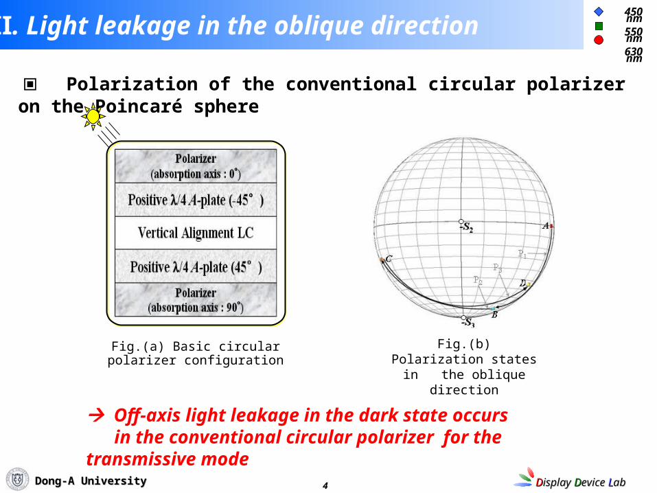
Ⅱ. Light leakage in the oblique direction
Off-axis light leakage in the dark state occurs in the conventional circular polarizer for the transmissive mode
▣ Polarization of the conventional circular polarizer on the Poincaré sphere
Fig.(a) Basic circular polarizer configuration
Fig.(b) Polarization states in the oblique direction
5 DDisplay isplay DDevice evice LLabab Dong-A UniversityDong-A University
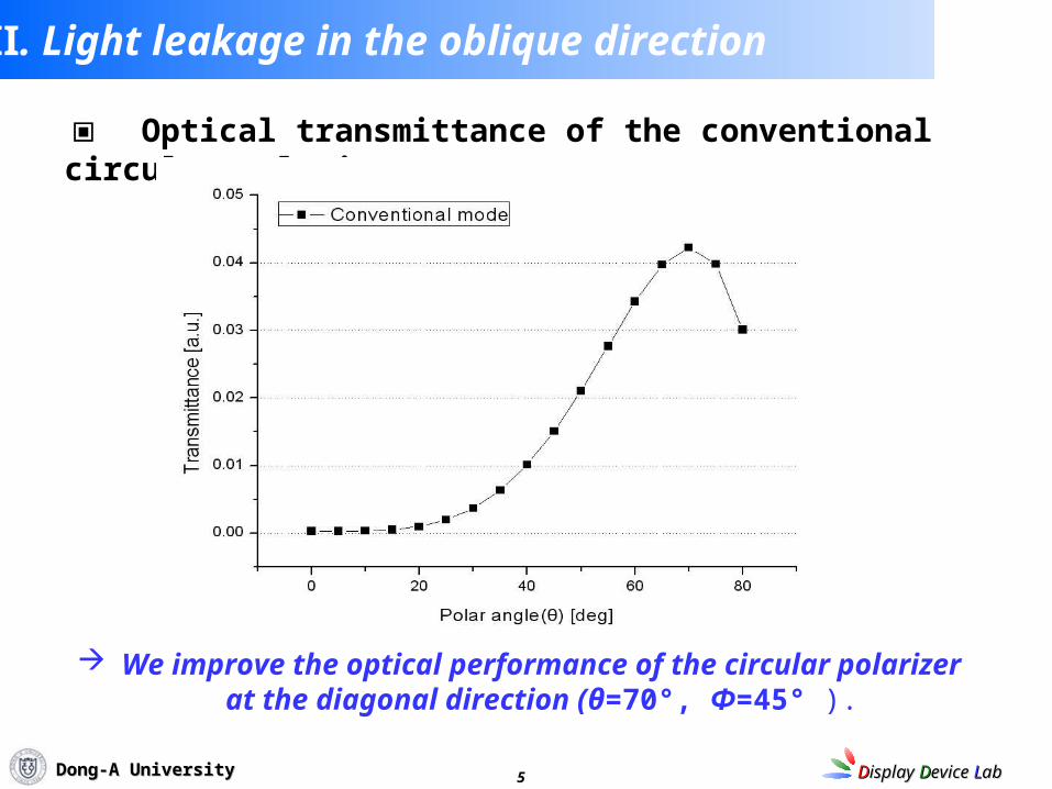
▣ Optical transmittance of the conventional circular polarier
We improve the optical performance of the circular polarizer at the diagonal direction (θ=70°, Φ=45° ).
Ⅱ. Light leakage in the oblique direction
6 DDisplay isplay DDevice evice LLabab Dong-A UniversityDong-A University
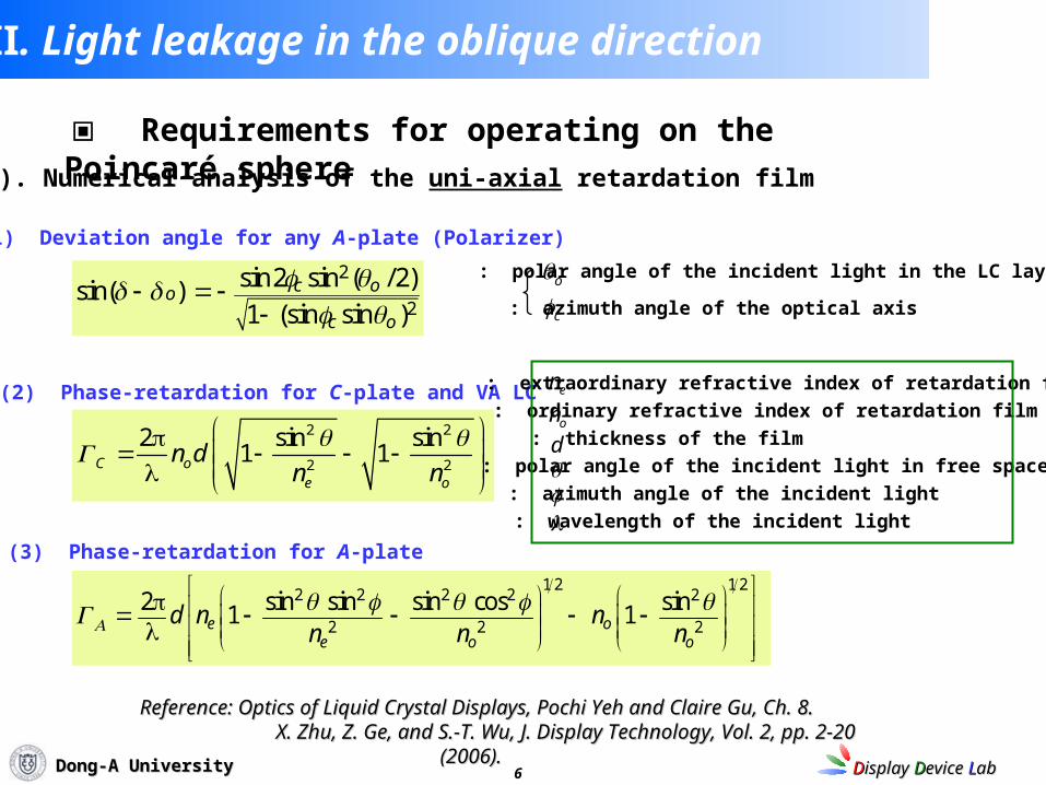
(1) Deviation angle for any A-plate (Polarizer)
o : polar angle of the incident light in the LC layer
c : azimuth angle of the optical axis
2
2
sin2 sin ( /2)sin( )1 (sin sin )
c o
c o
o
2 2
2 2
2 sin sin1 1C o
e o
n dn n
(2) Phase-retardation for C-plate and VA LC
▣ Requirements for operating on the Poincaré sphere
: polar angle of the incident light in free space
: azimuth angle of the incident light
en : extraordinary refractive index of retardation film
on : ordinary refractive index of retardation film
d : thickness of the film
: wavelength of the incident light
Reference: Optics of Liquid Crystal Displays, Pochi Yeh and Claire Gu, Ch. 8.Reference: Optics of Liquid Crystal Displays, Pochi Yeh and Claire Gu, Ch. 8. X. Zhu, Z. Ge, and S.-T. Wu, J. Display Technology, Vol. 2, pp. 2-20 (2006).X. Zhu, Z. Ge, and S.-T. Wu, J. Display Technology, Vol. 2, pp. 2-20 (2006).
(3) Phase-retardation for A-plate
1 2 1 22 2 2 2 2
2 2 2
sin sin sin cos2 sin1 1e oe o o
d n nn n n
Ⅱ. Light leakage in the oblique direction
1). Numerical analysis of the uni-axial retardation film
7 DDisplay isplay DDevice evice LLabab Dong-A UniversityDong-A University
θt
θi
x
y
zRegion 2
Region 1
vt
vi
ki
kt
krvr
Di
Dr
Dt
θr
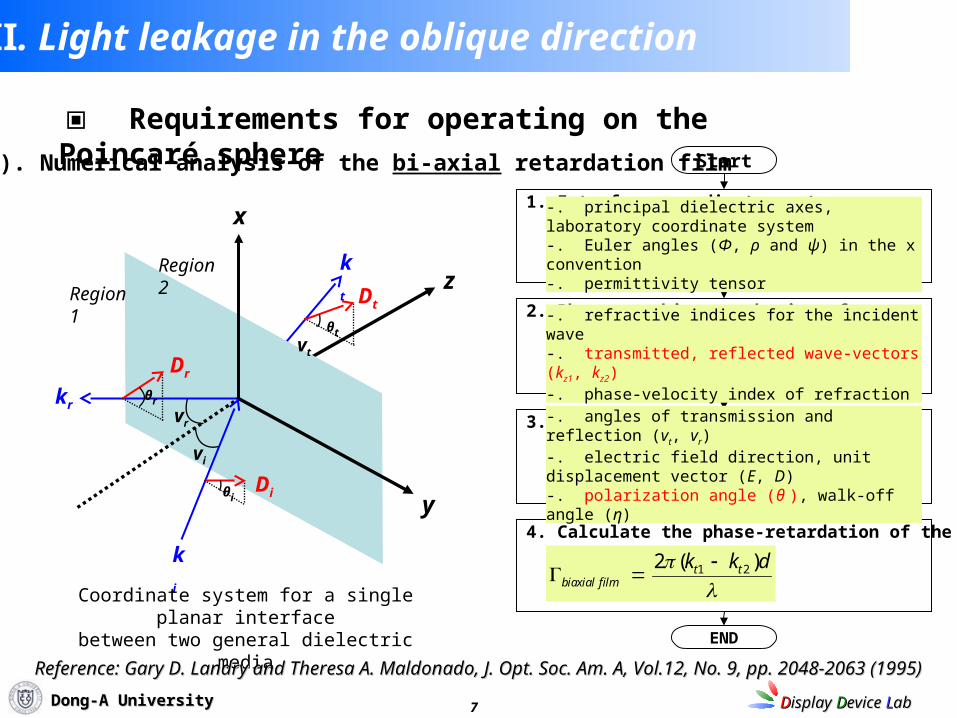
Coordinate system for a single planar interfacebetween two general dielectric media
Start
1. Interface coordinate system
2. Phase-matching at the interface
3. Characteristic angle for each wave
4. Calculate the phase-retardation of the biaxial film
END
-. principal dielectric axes, laboratory coordinate system-. Euler angles (Φ, ρ and ψ) in the x convention-. permittivity tensor
-. refractive indices for the incident wave-. transmitted, reflected wave-vectors (kz1, kz2)-. phase-velocity index of refraction
-. angles of transmission and reflection (vt, vr)-. electric field direction, unit displacement vector (E, D)-. polarization angle (θ ), walk-off angle (η)
1 22 ( )t tbiaxial film
k k d
Reference: Gary D. Landry and Theresa A. Maldonado, J. Opt. Soc. Am. A, Vol.12, No. 9, pp. 2048-2063 (1995)Reference: Gary D. Landry and Theresa A. Maldonado, J. Opt. Soc. Am. A, Vol.12, No. 9, pp. 2048-2063 (1995)
▣ Requirements for operating on the Poincaré sphere
2). Numerical analysis of the bi-axial retardation film
Ⅱ. Light leakage in the oblique direction
8 DDisplay isplay DDevice evice LLabab Dong-A UniversityDong-A University
Ⅲ. Optical design on the Poincaré sphere
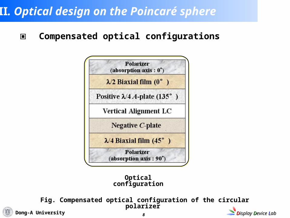
▣ Compensated optical configurations
Optical configuration
Fig. Compensated optical configuration of the circular polarizer
9 DDisplay isplay DDevice evice LLabab Dong-A UniversityDong-A University
Ⅲ. Optical design on the Poincaré sphere
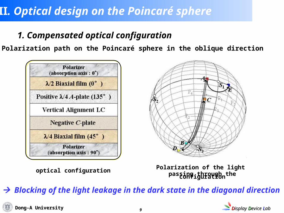
1. Compensated optical configuration
1) Polarization path on the Poincaré sphere in the oblique direction
Blocking of the light leakage in the dark state in the diagonal direction
optical configuration Polarization of the light passing through the configuration
10 DDisplay isplay DDevice evice LLabab Dong-A UniversityDong-A University
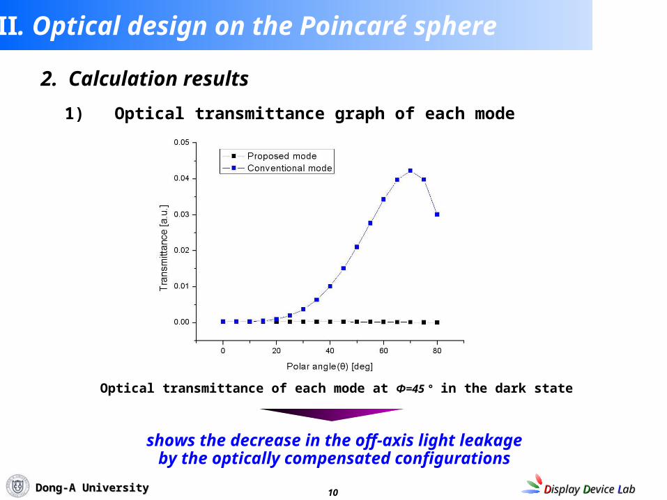
1) Optical transmittance graph of each mode
2. Calculation results
Ⅲ. Optical design on the Poincaré sphere
shows the decrease in the off-axis light leakageby the optically compensated configurations
Optical transmittance of each mode at Φ=45 ° in the dark state
11 DDisplay isplay DDevice evice LLabab Dong-A UniversityDong-A University
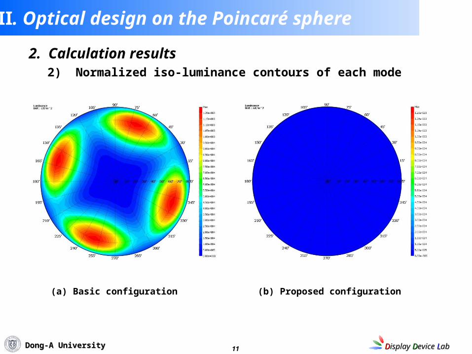
2. Calculation results
Ⅲ. Optical design on the Poincaré sphere
2) Normalized iso-luminance contours of each mode
(a) Basic configuration (b) Proposed configuration
12 DDisplay isplay DDevice evice LLabab Dong-A UniversityDong-A University
Ⅳ. Conclusion
We presented an optical configuration for the circular polarizers
that can provide wide viewing angle characteristics of the VA mode.
We could effectively get an achromatic dark state
through the compensation method on the Poincaré sphere.
The introduced circular polarizers for transmissive mode
can be one of the excellent solutions for mobile device
applications with wide viewing angle.
13 DDisplay isplay DDevice evice LLabab Dong-A UniversityDong-A University
Thank you for your attention !!!