Embed Size (px)
Citation preview
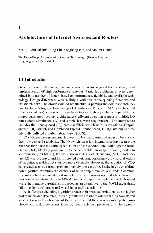
1
Architectures of Internet Switches and Routers
Xin Li, Lotfi Mhamdi, Jing Liu, Konghong Pun, and Mounir Hamdi
The Hong-Kong University of Science & Technology. {lixin,lotfi,liujing,konghong,hamdi}@cs.ust.hk
1.1 Introduction
Over the years, different architectures have been investigated for the design andimplementation of high-performance switches. Particular architectures were deter-mined by a number of factors based on performance, flexibility and available tech-nology. Design differences were mainly a variation in the queuing functions andthe switch core. The crossbar-based architecture is perhaps the dominant architec-ture for today’s high-performance packet switches (IP routers, ATM switches, andEthernet switches) and owes its popularity to its scalability (when compared to theshared-bus/shared-memory architectures), efficient operation (supports multiple I/Otransactions simultaneously) and simple hardware requirements. The architectureincludes the input-queued (IQ) crossbar fabric switch with its variations (Output-queued, OQ, switch and Combined Input–Output-queued, CIOQ, switch) and theinternally buffered crossbar fabric switch (BCS).
IQ switches have gained much interest in both academia and industry because oftheir low cost and scalability. The IQ switch has a low internal speedup because thecrossbar fabric has the same speed as that of the external line. Although the head-of-line (HoL) blocking problem limits the achievable throughput of an IQ switch toapproximately 58.6% [1], the well-known virtual output queuing (VOQ) architec-ture [2] was proposed and has improved switching performance by several ordersof magnitude, making IQ switches more desirable. However, the adoption of VOQhas created a more serious problem, namely, the centralized scheduler. An arbitra-tion algorithm examines the contents of all the input queues, and finds a conflict-free match between inputs and outputs. The well-known optimal algorithms (i.e.maximum-weight-matching or MWM) are too complex to implement at high speedwhile the iterative algorithms, proposed as an alternative to the MWM algorithms,fail to perform well under real world input traffic conditions.
As bufferless scheduling algorithms reach their practical limitations due to higherport numbers and data rates, internally buffered crossbar switches (BCS) have startedto attract researchers because of the great potential they have in solving the com-plexity and scalability issues faced by their bufferless predecessors. The increas-
2 X. Li et al.
ing demand for terabit switches and routers means that future commercial packetswitches must be implemented with reduced scheduling complexity. The bufferedcrossbar architecture can inherently implement distributed scheduling schemes andhas been considered a viable alternative to bufferless crossbar switches to improveperformance. The presence of internal buffers drastically improves the overall per-formance of the switch as it offers two distinct advantages. First, the adoption ofinternal buffers makes the scheduling totally distributed, dramatically reducing thearbitration complexity. Second, and most importantly, these internal buffers reduce(or avoid) output contention as they allow the inputs to make cell transfers concur-rently to a single output. While there have been many architectures for the (BCS)[3, 4, 5], our focus in this chapter is on BCS with VOQs (denoted by VOQ/BCS).
Despite the advantages that the VOQ/BCS architecture offers with regards to thebufferless architecture, both are seen as unscalable and unable to keep up with In-ternet growth in the foreseeable future. In fact, with progress in wavelength divisionmultiplexing (WDM) technology and optical fiber transmission, switches and routersare becoming the bottleneck of the overall system. The increasing data rates on theInternet are causing a scalability challenge for these crossbar-based architectures.This scalability limitation can be attributed to the nature of crossbar-based fabric,as a quadratic growth in the number of crosspoints puts a limit on chip area and/orpin counts. As a result, there is an urgent need for truly scalable high-performancepacket switches that has motivated researchers and industry to look for alternativeswitch fabrics. In particular, architectures such as the Clos-network switch architec-ture and the optical-electronic switch architecture are starting to receive attentionbecause of their great potential in entirely solving the scalability issues.
The Clos-network switch architecture is the most popular example among nu-merous examples of multi-stage switches in the communication world. It is mainlya three-stage switch as shown in Figure 1.11. There are switching elements (SE)at each stage which are connected. While the SEs can be any interconnect, typi-cally they are crossbars of smaller sizes. The SE at each stage of the Clos networkis capable of transmitting a packet from an input port to any of the output ports.Clos-network switches can be classified as buffered or bufferless, where the formeruses buffers to store packets in the second-stage SEs and the latter does not [6, 7].Buffers in the second-stage SEs can help resolve contention among packets fromdifferent first-stage modules but may cause a sequencing problem. While the Clos-network switches have been proposed for a some time now, relatively little research(especially compared to crossbars) has been conducted on making them scalable andhigh-speed packet switches that can serve the needs of the Internet. One of the goalsof the current survey is to fill this gap.
Given the effort put by both industry and academia into the all-electronic switch/router design, numerous studies show that all-electronic technology can no longer bea viable solution for the design of scalable switches/routers (i.e. 256 × 256 and be-yond). Alongside the scalability challenge, an electronic switch fabric becomes verycostly beyond a reasonable size (e.g. 128 × 128) and data rate (e.g. 10 Gb/s) due tothe ever-increasing power and chip count requirements for its implementation. More-over, current WDM systems offer 32–64 wavelengths at 2.5–10Gb/s/wavelength,
Architectures of Internet Switches and Routers 3
approaching a 1 Tb/s capacity, while research-level systems already exceed multi-terabits in a single fiber. As a result, traffic growth will not be limited by fiber band-width and/or optical components in the links. The total data rate of a single fiber isincreasing at a rate faster than the switching and routing equipment that terminatesand switches traffic at a carrier’s central office or point of presence (POP). In partic-ular, switches and routers are becoming the bottlenecks of the overall system. Whilethere has been a lot of attention paid to all-optical switches as a solution to this bottle-neck problem, most current POP switching equipment is electronic switches/routerswith optical I/O, and an all-optical solution in not expected to be viable in the fore-seeable future. For this reason, research focus is shifting towards a solution that takesadvantage of the strengths of both electronics and optics, with the ultimate goal ofdesigning practical switches and routers that can scale with the Internet traffic growthas well as keep up with the advances in WDM fiber transmission. Recently, attentionhas been given to hybrid optical–electronic architectures where the linecards andswitch scheduler are designed using electronics and the switch fabric is designedwith optical technology. This switch architecture provides advantages such as scala-bility, lower power consumption, and lower cost. However, a hybrid opto-electronicpacket switch/router presents a unique challenge: the reconfiguration time of an opti-cal switch fabric is much longer than that of an electronic fabric, and the end-to-endclock recovery in such a system adds to the reconfiguration overhead.
The goal of this chapter is to survey each of the above presented architectures,and will be organized as follows. Section 1.2 presents the bufferless switching ar-chitecture with its different types and scheduling schemes. Section 1.3 presents thebuffered crossbar switch architecture and discusses its scheduling processes and pro-posed schemes. In Section 1.4, we present the Clos-network architecture and discussits variants and scheduling. Section 1.5 presents the optical switching trend and thepotential for building such cost-effective and highly scalable switches. Section 1.6concludes the paper and suggests problems for further research.
1.2 Bufferless Crossbar Switches
1.2.1 Introduction to Switch Fabrics
Crossbar switch fabric is an active non-blocking switch fabric. In crossbar archi-tecture, each line card is connected by a dedicated point-to-point link to the centralswitch fabric. The inputs and outputs are connected at switching points, called cross-points. It is the scheduler’s responsibility to set configurations for the crosspointmatrix and for each configuration. One input/output can only be connected to oneoutput/input. The basic architecture of a crossbar switch is shown in Figure 1.1.
For bufferless crossbar switches, there is no buffer at the crosspoint. However,buffers may be placed at the input side, output side, or both. Based on where thebuffers are placed, bufferless crossbar switches are categorized into input-queuedswitches, output-queued switches, and combined input–output queued switches.
4 X. Li et al.
Figure 1.1. Crossbar architecture
1.2.2 Output-queued Switches
Traditionally, switches and routers have been most often designed with an outputqueuing strategy. This strategy has advantages in that guaranteed qualities-of-service(QoS) can be provided for the system, which is able to control packet departuretimes [8, 9]. An output-queued switch is attractive as it can always achieve 100%throughput. However, since there are no queues at the inputs, all arriving cells mustbe immediately delivered to their outputs. The necessary simultaneous delivery of allarriving cells to the outputs becomes a disadvantage if the requirements for internalinterconnection bandwidth and memory bandwidth are too great. For a switch with
input ports, there can be up to cells, one from each input, arriving at any oneoutput simultaneously. Thus, in order to receive all the cells at one time the memoryneeds a bandwidth of cell time write accesses. This requirement is referred to asthe internal speedup of the switch [10], so an output-queued switch has an internalspeedup of . The current demand for bandwidth is growing rapidly and as switchsizes continue to increase, memory bandwidth will be insufficient for output queuingto be practical.
1.2.3 Input-queued Switches
Memory bandwidth is not a problem with the input queuing strategy. In input-queuedswitches, arriving cells are buffered on the input side and extracted to pass throughthe switch fabric according to some arbitration algorithm. Contention within theswitch fabric and input/output interfaces is resolved by the arbitration algorithm(each input can deliver at most one cell to the switch in one cell time and each outputcan accept no more than one cell in one cell time).
Queuing Strategies
• Single FIFO and Head-of-line Blocking: It is relatively easy to implement sin-gle FIFO (first-in-first-out) switches. A single FIFO queue is used at each input
Architectures of Internet Switches and Routers 5
where only the first cell in each queue is eligible to be forwarded. Head-of-line(HoL) blocking may occur where no cell can be transmitted from an input be-cause of a contention of the first packet in the FIFO queue. Though the next cellin the queue may be without contention, it cannot be transmitted as this woulddisrupt the queue. Single FIFO switches suffering from HoL blocking result inpoor performance. It is well known that such a switch with Bernoulli I.I.D. ar-rivals under uniform traffic can only achieve a maximum throughput of 58.6%when the number of ports is large [1]. For periodic traffic, HoL blocking can leadto even worse performance [11].
• Windowing Mechanism: This mechanism enables the scheduler of the switch tolook ahead (window size) cells in the queue at a time, relieving the HoL block-ing problem and increasing performance by allowing cells behind the head of thequeue to be extracted. If the cell at the head of the queue cannot be transferred tothe intended output because of contention, the second cell is considered, and soon, up to the th queue position. Note that when = 1, it is single FIFO queu-ing. The performance of input-queued switches adopting this queue organizationgrows with , however, this gain is limited as the complexity of the queuingmechanism increases.
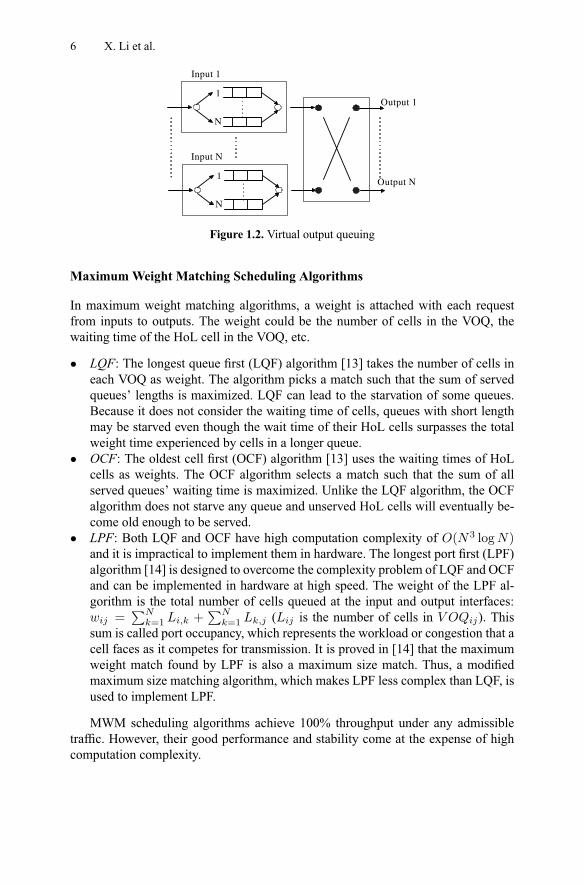
• Virtual Output Queuing: HoL blocking can be completely eliminated by using avirtual output queuing [2] architecture at the input side. Rather than maintaininga single FIFO queue for all cells, each input maintains a separate queue for eachoutput as shown in Figure 1.2. There are thus a total of 2 input queues, whereeach separate queue is called a VOQ and operates according to the FIFO disci-pline. The scheduler will select among the HoL cells of each VOQ and transmitthem. HoL blocking is eliminated as no cell can be held up by a cell ahead of itthat is destined for a different output. When virtual output queuing is employed,the performance of the switch depends on the scheduling algorithm that decideswhich cells should be transmitted during a cell time under the condition that onlyone cell can be delivered to each input and only one cell can be accepted at eachoutput. With suitable scheduling algorithms, an input-queued switch using vir-tual output queuing can increase the throughput from 58.6% to 100% for bothuniform and non-uniform traffic [12].
1.2.4 Scheduling Algorithms for VOQ Switches
Per one time slot, each input can send at most one cell and each output can receiveat most one cell. Scheduling algorithms are necessary for crossbar switches to find aproper one-to-one match between inputs and outputs in order to configure the cross-bar. A variety of scheduling algorithms are proposed for the VOQ architecture. Thissection presents an overview of some popular and effective schemes.
6 X. Li et al.
1
N
Input 1
1
N
Input N
Output 1
Output N
Figure 1.2. Virtual output queuing
Maximum Weight Matching Scheduling Algorithms
In maximum weight matching algorithms, a weight is attached with each requestfrom inputs to outputs. The weight could be the number of cells in the VOQ, thewaiting time of the HoL cell in the VOQ, etc.
• LQF: The longest queue first (LQF) algorithm [13] takes the number of cells ineach VOQ as weight. The algorithm picks a match such that the sum of servedqueues’ lengths is maximized. LQF can lead to the starvation of some queues.Because it does not consider the waiting time of cells, queues with short lengthmay be starved even though the wait time of their HoL cells surpasses the totalweight time experienced by cells in a longer queue.
• OCF: The oldest cell first (OCF) algorithm [13] uses the waiting times of HoLcells as weights. The OCF algorithm selects a match such that the sum of allserved queues’ waiting time is maximized. Unlike the LQF algorithm, the OCFalgorithm does not starve any queue and unserved HoL cells will eventually be-come old enough to be served.
• LPF: Both LQF and OCF have high computation complexity of ( 3 log )and it is impractical to implement them in hardware. The longest port first (LPF)algorithm [14] is designed to overcome the complexity problem of LQF and OCFand can be implemented in hardware at high speed. The weight of the LPF al-gorithm is the total number of cells queued at the input and output interfaces:
=P
=1 +P
=1 ( is the number of cells in ). Thissum is called port occupancy, which represents the workload or congestion that acell faces as it competes for transmission. It is proved in [14] that the maximumweight match found by LPF is also a maximum size match. Thus, a modifiedmaximum size matching algorithm, which makes LPF less complex than LQF, isused to implement LPF.
MWM scheduling algorithms achieve 100% throughput under any admissibletraffic. However, their good performance and stability come at the expense of highcomputation complexity.
Architectures of Internet Switches and Routers 7
Approximating Maximum Size Matching Scheduling Algorithms
Approximating maximum size matching algorithms are fast and simple to imple-ment in hardware with today’s technologies. They provide 100% throughput underuniform traffic and fairly good delay performance as well. However, they are not sta-ble under non-uniform traffic. Most of the approximating maximum size matchingalgorithms are iterative algorithms.
• PIM: The Parallel Iterative Matching (PIM) [15] algorithm attempts to approxi-mate a maximum size matching algorithm by iteratively matching the inputs tothe outputs until it finds a maximum size match. Each iteration consists of threesteps:Step 1. Request. Each unmatched input sends a request to every output for whichit has a queued cell.Step 2. Grant. If an unmatched output receives any requests, it grants one byrandomly selecting from all requests.Step 3. Accept. If an input receives more than one grant, it accepts one by randomselection.The PIM algorithm faces some problems. First, randomness is difficult and ex-pensive to implement at high speed. Each arbiter must make a random selectionamong the members of a time-varying set. Second, when the switch is oversub-scribed, PIM can lead to unfairness between connections. Finally, PIM does notperform well for a single iteration: it limits the throughput to approximately 63%,only slightly higher than a FIFO switch.
• Round-robin scheduling: All existing round-robin scheduling algorithms havethe same three steps as PIM. Instead of randomly matching cells, the input andoutput arbiter adopts a round-robin scheme where the inputs and outputs taketurns. Round-robin scheduling overcomes two problems in PIM: complexity andunfairness. Implemented as priority encoders, the round-robin arbiters are muchsimpler and can perform faster than random arbiters. The rotating scheme makesthe algorithm assign bandwidth equally and more fairly among requests.
– iSLIP: One iteration of iSLIP [2] consists of three steps:Step 1. Request. Each unmatched input sends a request to every output forwhich it has a queued cell.Step 2. Grant. If an output receives any requests, it chooses the one that ap-pears next in a fixed, round-robin schedule starting from the highest priorityelement. The output notifies each input whether or not its request was granted.The pointer to the highest priority element of the round-robin schedule is in-cremented (modulo ) to one location beyond the granted input if and onlyif the grant is accepted in Step 3. If no request is received, the pointer staysunchanged.Step 3. Accept. If an input receives a grant, it accepts the one that appearsnext in a fixed round-robin schedule starting from the highest priority ele-ment. The pointer to the highest priority element of the round-robin schedule
8 X. Li et al.
is incremented (modulo ) to one location beyond the accepted one. If nogrant is received, the pointer stays unchanged. iSLIP updates the grant point-ers only when the grant is accepted. In this scheme, starvation is avoided.
– FIRM: FCFS in round-robin matching (FIRM) [16] achieves improved fair-ness (as it approximates FCFS) and has tighter service guarantee than iSLIP.The only difference between iSLIP and FIRM lies in Step 2. FIRM movesthe grant pointer regardless of whether the grant is accepted or not, i.e.:Step 2. Grant. If an output receives any requests, it chooses the one thatappears next in a fixed, round-robin schedule starting from the highest pri-ority element. The output notifies each input whether or not its request wasgranted. The pointer to the highest priority element of the round-robin sched-ule is incremented (modulo ) to one location beyond the granted input ifand only if the grant is accepted in Step 3. If the grant is not accepted, thepointer is placed to the granted input. If no request is received, the pointerstays unchanged.
The modification of the grant pointer results in enhanced fairness in terms ofFCFS service, i.e. FIRM approximates FCFS closer than iSLIP with the use ofthe round-robin pointers. FIRM achieves this as it forces the scheduler to issuethe next grant to the unsuccessful request until the grant is accepted while iSLIPmay take the newly arrived request first.
Randomized Scheduling Algorithms
The motivation for proposing randomized algorithms is to overcome the complexityof MWM algorithms and to achieve stability under any admissible traffic.
• TASS: TASS [17] is the basic randomized algorithm proposed by Tassiulus. Thesteps for this algorithm are as follows:(a) Let ( ) be the schedule used at time .(b) At time + 1 choose a match ( + 1) uniformly at random from the set ofall ! possible matches.(c) Let ( + 1) = max ( + 1) ( ( + 1) is the queue-lengthsmatrix at time + 1.)It was proven that if the probability of ( + 1) being equivalent to the max-imum weight matching is lower bounded by some constant , the algorithm isstable. Although TASS achieves stability under any admissible traffic, it does nothave good delay performance, especially under non-uniform traffic. Recently, agroup of randomized algorithms including APSARA, LAURA, and SERENAwere proposed [18]. The motivation behind these algorithms is to improve thedelay performance by exploiting some features of the switching problem whilemaintaining stability.
Architectures of Internet Switches and Routers 9
• APSARA: APSARA [18] selects a match for the current time slot based on threeinputs: the match of the last time slot ( ), neighbors of the match ( ), and arandomly chosen match ( +1). A neighbor of a match , denoted as ( ( )),is obtained by exchanging the input/output pair of two connections in the match.The weight is then computed from these inputs and chosen as the maximummatch time at + 1. The neighbor is used here with the objective of searching thespace matches in parallel.
• LAURA: LAURA [18] differs from APSARA in that LAURA uses a non-uniform random sampling which has the purpose of keeping heavy edges in thematching procedure and a corresponding merging procedure for weight augmen-tation. By merging the matches of the randomly chosen ( + 1) with the matchof last time slot ( ), a match with increased weight is obtained. Notice that whencompared with TASS, ‘merge’ is used instead of ‘max’ due to the performanceimprovement obtained with the merging algorithms.
• SERENA: SERENA [18] makes some modifications to LAURA where it usesthe arrival information in the merging procedure. The arrival graph, ( + 1),is one component in the merging procedure and is directly used when it is amatch. Otherwise, modification to ( + 1) is required in order to yield a match.This information is used based on the observation that the accumulation of queuelengths is due to arrival events, which also serve as a source of randomness.
Performance Comparison among Algorithms
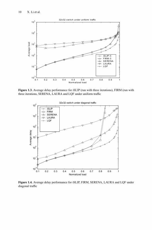
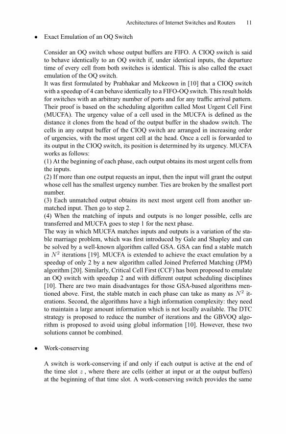
MWM algorithms perform very well in terms of both delay and stability. However,the computation complexity required to implement them is generally too high to bepractical. The more practical approximating MSM algorithms perform well underuniform traffic, but are not stable under non-uniform traffic. Randomized algorithmsare linear in complexity and provide the benefit of being stable under any admissibletraffic as well. However, the delay encountered is higher than that of approximatingMSM algorithms, as randomized algorithms have been designed with objectives ofstability rather than small average delay. Figure 1.3 shows the average delay underuniform traffic for these typical algorithms. Figure 1.4 compares the average delayof the same algorithms under diagonal traffic.
1.2.5 Combined Input–Output-queued Switches
VOQs and an increase in the internal speedup of a switch are used to solve the HoLblocking problem. If the switch fabric has an internal speedup, i.e. a few times fasterthan the line rate, buffers are required at both input and output sides. This is a com-bined input–output queued (CIOQ) switch, which can emulate an OQ switch witha small speedup. There are two emulation schemes: emulating an OQ switch onthroughput and emulating both throughput and cell delivery order.
10 X. Li et al.
0.1 0.2 0.3 0.4 0.5 0.6 0.7 0.8 0.9 110
-2
10-1
100
101
102
103
32x32 switch under uniform traffic
Norm alized load
Av
era
ge
lo
ad
iSLIP -3FIRM -3 SE RE NA LA URA LQF
Figure 1.3. Average delay performance for iSLIP (run with three iterations), FIRM (run withthree iterations, SERENA, LAURA and LQF under uniform traffic
0.1 0.2 0.3 0.4 0.5 0.6 0.7 0.8 0.9 110
-2
10-1
100
101
102
103
104
32x32 switch under diagonal traffic
Normalized load
Ave
rage
del
ay
iSLIP FIRM SERENA LAURA LQF
Figure 1.4. Average delay performance for iSLIP, FIRM, SERENA, LAURA and LQF underdiagonal traffic
Architectures of Internet Switches and Routers 11
• Exact Emulation of an OQ Switch
Consider an OQ switch whose output buffers are FIFO. A CIOQ switch is saidto behave identically to an OQ switch if, under identical inputs, the departuretime of every cell from both switches is identical. This is also called the exactemulation of the OQ switch.It was first formulated by Prabhakar and Mckeown in [10] that a CIOQ switchwith a speedup of 4 can behave identically to a FIFO-OQ switch. This result holdsfor switches with an arbitrary number of ports and for any traffic arrival pattern.Their proof is based on the scheduling algorithm called Most Urgent Cell First(MUCFA). The urgency value of a cell used in the MUCFA is defined as thedistance it clones from the head of the output buffer in the shadow switch. Thecells in any output buffer of the CIOQ switch are arranged in increasing orderof urgencies, with the most urgent cell at the head. Once a cell is forwarded toits output in the CIOQ switch, its position is determined by its urgency. MUCFAworks as follows:(1) At the beginning of each phase, each output obtains its most urgent cells fromthe inputs.(2) If more than one output requests an input, then the input will grant the outputwhose cell has the smallest urgency number. Ties are broken by the smallest portnumber.(3) Each unmatched output obtains its next most urgent cell from another un-matched input. Then go to step 2.(4) When the matching of inputs and outputs is no longer possible, cells aretransferred and MUCFA goes to step 1 for the next phase.The way in which MUCFA matches inputs and outputs is a variation of the sta-ble marriage problem, which was first introduced by Gale and Shapley and canbe solved by a well-known algorithm called GSA. GSA can find a stable matchin 2 iterations [19]. MUCFA is extended to achieve the exact emulation by aspeedup of only 2 by a new algorithm called Joined Preferred Matching (JPM)algorithm [20]. Similarly, Critical Cell First (CCF) has been proposed to emulatean OQ switch with speedup 2 and with different output scheduling disciplines[10]. There are two main disadvantages for those GSA-based algorithms men-tioned above. First, the stable match in each phase can take as many as 2 it-erations. Second, the algorithms have a high information complexity: they needto maintain a large amount information which is not locally available. The DTCstrategy is proposed to reduce the number of iterations and the GBVOQ algo-rithm is proposed to avoid using global information [10]. However, these twosolutions cannot be combined.
• Work-conserving
A switch is work-conserving if and only if each output is active at the end ofthe time slot , where there are cells (either at input or at the output buffers)at the beginning of that time slot. A work-conserving switch provides the same
12 X. Li et al.
. ..
. ..
N
N
1
O u tp u t
Figure 1.5. Pure buffered crossbar architecture
throughput performance as an OQ switch. The Lowest Occupancy Output FirstAlgorithm (LOOFA) has been proposed in [21] with the work-conserving prop-erty in a CIOQ switch with a speedup of 2. An integer variable, occupancy, isassociated with each output queue in LOOFA. The occupancy of an input atany time is simply the number of cells currently residing in output ’s buffer.(1) Each unmatched input selects the non-empty VOQ going to an unmatchedoutput with the lowest occupancy and sends a request to that output.(2) The output, upon receiving requests from multiple inputs, selects one andsends a grant to that input.(3) The switch returns to step 1 until no more matches can be made.This algorithm essentially gives priority to output channels with low occupancy,thereby attempting to simultaneously maintain work conservation across all out-put channels. The work conserving feature of the switch is independent of theselection algorithm used at the outputs.
1.3 Buffered Crossbar Switches
1.3.1 Buffered Crossbar Switches Overview
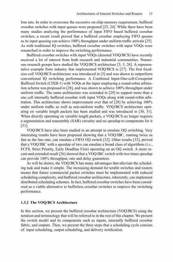
For many years, buffered crossbar switches have been considered a viable solution toimprove the switching throughput as an alternative to bufferless crossbar switches.Buffered crossbar switches have been studied for at least two decades [4, 22, 23].In an architecture called pure buffered crossbar, as shown in Figure 1.5, bufferingoccurs exclusively at the crosspoints and is utilized to minimize cell loss. The numberof ports is limited by the memory amount that can be implemented in a module chip.An example of this architecture was proposed in [4], where a 2 × 2 switch modulewith a crosspoint memory of 16 Kbytes each was implemented.
Unfortunately, at that time, it was not possible to embed enough buffering on-chip and therefore this architecture was unable to comply with the required cell
C r o ssp o in t B u ffer
...In p u t
1
...
Architectures of Internet Switches and Routers 13
loss rate. In order to overcome the excessive on-chip memory requirement, bufferedcrossbar switches with input queues were proposed [23, 24]. While there have beenmany studies analyzing the performance of input FIFO based buffered crossbarswitches, a recent result proved that a buffered crossbar employing FIFO queuesas its input queuing can achieve 100% throughput under uniform traffic arrivals [25].As with traditional IQ switches, buffered crossbar switches with input VOQs wereresearched in order to improve the switching performance.
Buffered crossbar switches with input VOQs (denoted VOQ/BCS) have recentlyreceived a lot of interest from both research and industrial communities. Numer-ous research groups have studied the VOQ/BCS architecture [3, 5, 26]. A represen-tative example from industry that implemented VOQ/BCS is [27]. The first fixed-size-cell VOQ/BCS architecture was introduced in [3] and was shown to outperformconventional IQ switching performance. A Combined Input-One-cell-CrosspointBuffered Switch (CIXB-1) with VOQs at the input employing a round-robin arbitra-tion scheme was proposed in [28], and was shown to achieve 100% throughput underuniform traffic. The same architecture was extended in [29] to support more than aone cell internally buffered crossbar with input VOQs along with round-robin arbi-tration. This architecture shows improvement over that of [28] by achieving 100%under uniform traffic as well as non-uniform traffic. VOQ/BCS architecture oper-ating on variable length packets has been studied and was introduced in [30, 31].When directly operating on variable length packets, a VOQ/BCS no longer requiresa segmentation and reassembly (SAR) circuitry and no speedup to compensate for it[31].
VOQ/BCS have also been studied in an attempt to emulate OQ switching. Veryinteresting results have been proposed showing that a VOQ/IBC, running twice asfast as the line rate, can emulate a FIFO OQ switch [32]. Other results [33], provedthat a VOQ/IBC with a speedup of two can emulate a broad class of algorithms (i.e.,FCFS, Strict Priority, Early Deadline First) operating on an OQ switch. A more re-cent and extended result [26] showed that a VOQ/IBC switch with two times speedupcan provide 100% throughput, rate and delay guarantees.
As will be shown, the VOQ/BCS has many advantages that alleviate the schedul-ing task and make it simple. The increasing demand for terabit switches and routersmeans that future commercial packet switches must be implemented with reducedscheduling complexity, and buffered crossbar architecture, inherently, can implementdistributed scheduling schemes. In fact, buffered crossbar switches have been consid-ered as a viable alternative to bufferless crossbar switches to improve the switchingperformance.
1.3.2 The VOQ/BCS Architecture
In this section, we present the buffered crossbar architecture (VOQ/BCS) using thenotation and terminology that will be referred to in the rest of this chapter. We presentthe switch model and its components such as inputs, internally buffered crossbarfabric, and outputs. Then, we present the three steps that a scheduling cycle consistsof: input scheduling, output scheduling, and delivery notification.
14 X. Li et al.
. . .
N 1
N
1 1
N
. . .. . .
. . .. . .
1 N
Internal crosspoint bufferFlow Control
Data
Input Card
Arbiter Arbiter
Output CardOutput Card
Arbiter
Arbiter
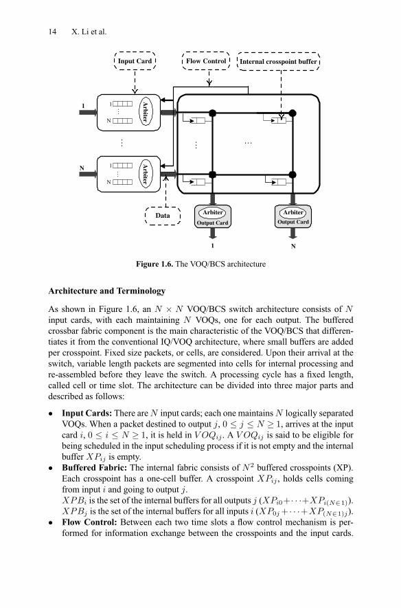
Figure 1.6. The VOQ/BCS architecture
Architecture and Terminology
As shown in Figure 1.6, an × VOQ/BCS switch architecture consists ofinput cards, with each maintaining VOQs, one for each output. The bufferedcrossbar fabric component is the main characteristic of the VOQ/BCS that differen-tiates it from the conventional IQ/VOQ architecture, where small buffers are addedper crosspoint. Fixed size packets, or cells, are considered. Upon their arrival at theswitch, variable length packets are segmented into cells for internal processing andre-assembled before they leave the switch. A processing cycle has a fixed length,called cell or time slot. The architecture can be divided into three major parts anddescribed as follows:
• Input Cards: There are input cards; each one maintains logically separatedVOQs. When a packet destined to output , 0 1, arrives at the inputcard , 0 1, it is held in . A is said to be eligible forbeing scheduled in the input scheduling process if it is not empty and the internalbuffer is empty.
• Buffered Fabric: The internal fabric consists of 2 buffered crosspoints (XP).Each crosspoint has a one-cell buffer. A crosspoint , holds cells comingfrom input and going to output .
is the set of the internal buffers for all outputs ( 0+· · ·+ ( 1)).is the set of the internal buffers for all inputs ( 0 + · · ·+ ( 1) ).
• Flow Control: Between each two time slots a flow control mechanism is per-formed for information exchange between the crosspoints and the input cards.
Architectures of Internet Switches and Routers 15
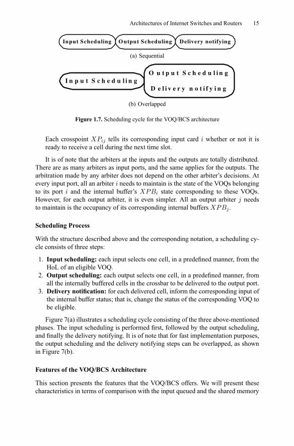
Input Scheduling O utput Scheduling Delivery notifying
(a) Sequential
I n p u t S c h e d u l i n gO u t p u t S c h e d u l i n g
D e l i v e r y n o t i f y i n g
(b) Overlapped
Figure 1.7. Scheduling cycle for the VOQ/BCS architecture
Each crosspoint tells its corresponding input card whether or not it isready to receive a cell during the next time slot.
It is of note that the arbiters at the inputs and the outputs are totally distributed.There are as many arbiters as input ports, and the same applies for the outputs. Thearbitration made by any arbiter does not depend on the other arbiter’s decisions. Atevery input port, all an arbiter needs to maintain is the state of the VOQs belongingto its port and the internal buffer’s state corresponding to these VOQs.However, for each output arbiter, it is even simpler. All an output arbiter needsto maintain is the occupancy of its corresponding internal buffers .
Scheduling Process
With the structure described above and the corresponding notation, a scheduling cy-cle consists of three steps:
1. Input scheduling: each input selects one cell, in a predefined manner, from theHoL of an eligible VOQ.
2. Output scheduling: each output selects one cell, in a predefined manner, fromall the internally buffered cells in the crossbar to be delivered to the output port.
3. Delivery notification: for each delivered cell, inform the corresponding input ofthe internal buffer status; that is, change the status of the corresponding VOQ tobe eligible.
Figure 7(a) illustrates a scheduling cycle consisting of the three above-mentionedphases. The input scheduling is performed first, followed by the output scheduling,and finally the delivery notifying. It is of note that for fast implementation purposes,the output scheduling and the delivery notifying steps can be overlapped, as shownin Figure 7(b).
Features of the VOQ/BCS Architecture
This section presents the features that the VOQ/BCS offers. We will present thesecharacteristics in terms of comparison with the input queued and the shared memory
16 X. Li et al.
B A
B C
(a) 2× 2 IQ crossbar switch
B A
B C
(b) 2× 2 buffered crossbar switch
Figure 1.8. Architecture comparison of bufferless and buffered crossbar
architecture. Compared to the existing architectures, the VOQ/BCS architecture hassubstantial advantages. They can be summarized as follows:
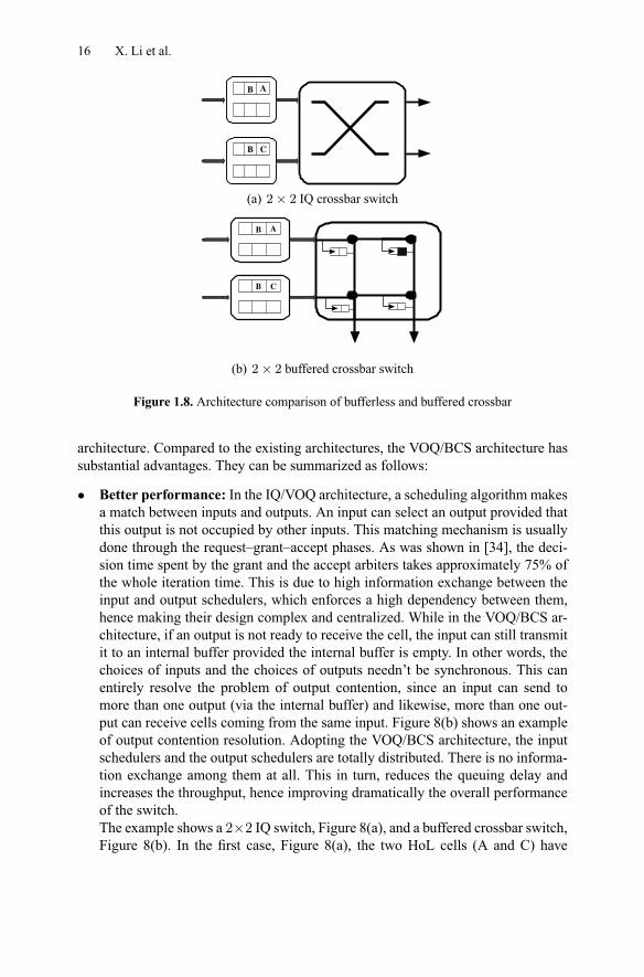
• Better performance: In the IQ/VOQ architecture, a scheduling algorithm makesa match between inputs and outputs. An input can select an output provided thatthis output is not occupied by other inputs. This matching mechanism is usuallydone through the request–grant–accept phases. As was shown in [34], the deci-sion time spent by the grant and the accept arbiters takes approximately 75% ofthe whole iteration time. This is due to high information exchange between theinput and output schedulers, which enforces a high dependency between them,hence making their design complex and centralized. While in the VOQ/BCS ar-chitecture, if an output is not ready to receive the cell, the input can still transmitit to an internal buffer provided the internal buffer is empty. In other words, thechoices of inputs and the choices of outputs needn’t be synchronous. This canentirely resolve the problem of output contention, since an input can send tomore than one output (via the internal buffer) and likewise, more than one out-put can receive cells coming from the same input. Figure 8(b) shows an exampleof output contention resolution. Adopting the VOQ/BCS architecture, the inputschedulers and the output schedulers are totally distributed. There is no informa-tion exchange among them at all. This in turn, reduces the queuing delay andincreases the throughput, hence improving dramatically the overall performanceof the switch.The example shows a 2×2 IQ switch, Figure 8(a), and a buffered crossbar switch,Figure 8(b). In the first case, Figure 8(a), the two HoL cells (A and C) have
Architectures of Internet Switches and Routers 17
0.3 0.4 0.5 0.6 0.7 0.8 0.9 1
100
101
102
103
Ave
rage
Del
ay
Normalized Load
32x32 Switch under Bernoulli Uniform Traffic
OQRR-RR1-SLIP4-SLIP
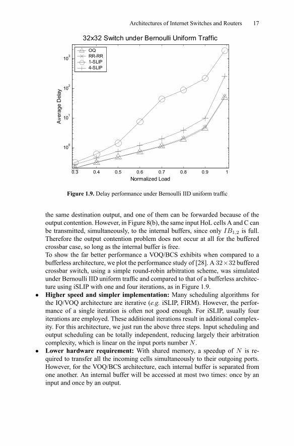
Figure 1.9. Delay performance under Bernoulli IID uniform traffic
the same destination output, and one of them can be forwarded because of theoutput contention. However, in Figure 8(b), the same input HoL cells A and C canbe transmitted, simultaneously, to the internal buffers, since only 1 2 is full.Therefore the output contention problem does not occur at all for the bufferedcrossbar case, so long as the internal buffer is free.To show the far better performance a VOQ/BCS exhibits when compared to abufferless architecture, we plot the performance study of [28]. A 32×32 bufferedcrossbar switch, using a simple round-robin arbitration scheme, was simulatedunder Bernoulli IID uniform traffic and compared to that of a bufferless architec-ture using iSLIP with one and four iterations, as in Figure 1.9.
• Higher speed and simpler implementation: Many scheduling algorithms forthe IQ/VOQ architecture are iterative (e.g. iSLIP, FIRM). However, the perfor-mance of a single iteration is often not good enough. For iSLIP, usually fouriterations are employed. These additional iterations result in additional complex-ity. For this architecture, we just run the above three steps. Input scheduling andoutput scheduling can be totally independent, reducing largely their arbitrationcomplexity, which is linear on the input ports number .
• Lower hardware requirement: With shared memory, a speedup of is re-quired to transfer all the incoming cells simultaneously to their outgoing ports.However, for the VOQ/BCS architecture, each internal buffer is separated fromone another. An internal buffer will be accessed at most two times: once by aninput and once by an output.
18 X. Li et al.
However, for a large number of inputs/outputs, the number of internal buffersbecomes huge (since it equals 2). Even though VLSI density increases make itpossible to embed enough memory on chip, it can still be quite difficult to put somuch memory on a crossbar. One way to make the implementation easier is by mov-ing the internal buffers out of the crossbar and putting them at the input side of thechip and adding two multiplexers. The first multiplexer at each input chooses oneamong the N VOQs and sends the HoL packet to the internal buffers, and the secondmultiplexer chooses one internal buffer according to the packet’s destination outputin which to put the received packet. Another implementation variant is putting theinternal buffers at the output side instead of the input. The multiplexer at an outputchooses one internal buffer to receive a packet and then sends it out. It is quite clearthat the two variants are equivalent to the original architecture. We believe that thesetwo alternative layouts are less complicated and more scalable than the conventionalone.
Scheduling Cells in the VOQ/BCS Architecture
As bufferless scheduling algorithms reached their practical limitations due to higherport numbers and data rates, buffered crossbars received increased interest becausethey have the potential to solve the complexity and scalability issues faced by theirbufferless predecessors. The increasing need for terabit switches and routers meansthat future commercial packet switches must be implemented with reduced schedul-ing complexity, and buffered crossbar architectures, inherently, can implement dis-tributed scheduling schemes.
In the past few years, many scheduling schemes have been proposed for theVOQ/BCS architecture. The first, [3], used input and output arbitration schemesbased on the Oldest Cell First. The second scheme presented was based on round-robin arbitration in both input and output scheduling [28]. While these two schemeswere proven to achieve 100% throughput under uniform traffic, they performedrather poorly under non-uniform traffic patterns. To overcome this, a scheme basedon Longest Queue First (LQF) input scheduling followed by a round-robin arbitra-tion scheme in the output side was proposed and demonstrated 100% throughputunder uniform traffic patterns.
It is of note that the algorithms presented above were compared with buffer-less schemes and were demonstrated, as expected, to have much better performance.However, as mentioned earlier, the VOQ/BCS has key advantages that ensure thescheduling algorithm is simple and efficient at the same time. So far, most existingalgorithms (OCF, RR, and LQF) are just simple mappings of previously proposedalgorithms for bufferless crossbar switches into the new VOQ/BCS architecture.
The presence of internal buffers significantly improves the overall performanceof the switch due to the advantages it offers. A scheme that takes full advantageof the internal buffers was recently presented in [35]. This scheme was, in fact, anapproximation of the First Come First Served (FCFS) policy. It was based on theCurrently Arrival First (CAF) cell in the input scheduling followed by a priority
Architectures of Internet Switches and Routers 19
0.7 0.75 0.8 0.85 0.9 0.95 1
500
1000
1500
2000
2500
3000
3500
4000
4500
5000
5500
Ave
rage
Del
ay
Normalized Load
32x32 switch under Bursty uniform traffic, l=100
SBF-LBFLQF-RROCF-OCF
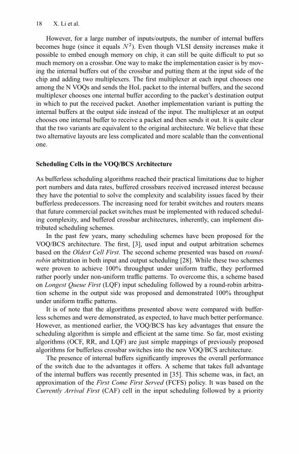
Figure 1.10. Delay performance under bursty uniform traffic, l =100
scheme called Priority ReMoVal (PRMV). A scheme that exclusively used the inter-nal buffers was also proposed [36]. This scheme is called the Most Critical internalBuffer First (MCBF), and is based on the Shortest internal Buffer First (SBF) at theinput scheduling and on the Longest internal Buffer First (LBF) at the output side.The authors addressed the important role that the internal buffer element plays in thescheduling process due to its shared nature. While being a stateless scheme, MCBFoutperforms weighted scheduling schemes such as LQF and OCF. Figure 1.10 showsthe delay performance of MCBF, LQF-RR and OCF-OCF under uniform burst trafficwith burst length equal to 100.
1.4 Multi-stage Switching
1.4.1 Architecture Choice
Clos-network switch architectures can be categorized into two types. The first typehas buffers in the second stage, such as the WUGS architecture in [6]. The functionof the buffers is to resolve contention among cells from different first-stage modules.However, cells may be mis-sequenced at the output ports, requiring a re-sequencefunction, which is difficult to implement when the port speed increases. The sec-ond type of architecture has no buffers in the second stage and uses shared memorymodules in the first and last stages to aggregate cells. The ATLANTA switch with
20 X. Li et al.
its Memory/Space/Memory (MSM) architecture is a commercially successful exam-ple [7]. This architecture is more promising as no mis-sequence problem exists. Wedescribe several dispatching algorithms for the MSM architecture, including con-current dispatching (CD), concurrent round-robin dispatching (CRRD), concurrentmaster–slave round-robin dispatching (CMSD), and concurrent static round-robindispatching (SRRD).
However, one disadvantage of the MSM architecture is that the input and out-put stages are both composed of shared-memory modules, introducing a mem-ory speedup problem. Although the speedup is smaller than that in output-queuedswitches, it definitely hinders the switch’s ability to scale up to very large port num-bers.
The memory speedup problem was solved by the bufferless Clos-network archi-tecture proposed in [37]. This architecture contains only crossbar switching elementsin all stages. All cells are stored in the input port cards, as done with the virtual out-put queuing structure in single-stage crossbar switches. Since the switching elementsare fully distributed by smaller modules, this raises the challenge of how to designthe scheduling algorithm in a fully distributed way. We then describe the Distro dis-patching algorithm for the bufferless Clos-network architecture.
1.4.2 The MSM Clos-network Architecture
Switch Model
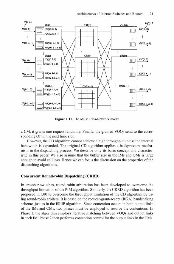
The switch architecture used in this paper is based on [37] and is shown in Figure1.11. The input and output stages are both composed of shared-memory modules,each with port interfaces. They are fully interconnected through a central stagethat consists of bufferless crossbars of size × . In the switch, there are inputmodules (IM), central modules (CM), and output modules (OM).
An OM( ) has buffered output ports, OP( , ). Each output port buffer canreceive at most cells from central modules and send at most one cell to theoutput line in one time slot.
An IM( ) has virtual output queues, VOQ( ), for storing cells that gofrom IM( ) to OP( ) at OM( ). Each virtual output queue can receive at mostcells from input ports and send one cell to the central module. We use VOQ Group( ) to represent all VOQs storing cells from IM( ) to OM( ).
An IM( ) has output links, LI( ), connecting to each CM( ). An CM( ) hasoutput links, LC( ), connecting to each OM( ).
Concurrent Dispatching (CD)
The distributed architecture implies the presence of multiple contention points in theswitch. The ATLANTA switch proposed the CD algorithm with highly distributednature [7, 38]. It works as follows.
In each time slot, each IM randomly selects up to VOQs and randomly sendsthe requests to CMs. If there is more than one request for the same output link in
Architectures of Internet Switches and Routers 21
Figure 1.11. The MSM Clos-Network model
a CM, it grants one request randomly. Finally, the granted VOQs send to the corre-sponding OP in the next time slot.
However, the CD algorithm cannot achieve a high throughput unless the internalbandwidth is expanded. The original CD algorithm applies a backpressure mecha-nism in the dispatching process. We describe only its basic concept and character-istic in this paper. We also assume that the buffer size in the IMs and OMs is largeenough to avoid cell loss. Hence we can focus the discussion on the properties of thedispatching algorithms.
Concurrent Round-robin Dispatching (CRRD)
In crossbar switches, round-robin arbitration has been developed to overcome thethroughput limitation of the PIM algorithm. Similarly, the CRRD algorithm has beenproposed in [39] to overcome the throughput limitation of the CD algorithm by us-ing round-robin arbiters. It is based on the request-grant-accept (RGA) handshakingscheme, just as in the iSLIP algorithm. Since contention occurs in both output linksof the IMs and CMs, two phases must be employed to resolve the contentions. InPhase 1, the algorithm employs iterative matching between VOQs and output linksin each IM. Phase 2 then performs contention control for the output links in the CMs.
22 X. Li et al.
Phase 1: Iteractively Matching within IM:
• Step 1 Request: Each unmatched, non-empty VOQ( ) sends a request toevery output link LI( ).
• Step 2 Grant: Each output link LI( ) selects one request with the round-robinarbiter and sends the grant to the selected VOQ.
• Step 3 Accept: Each VOQ V( ) selects one grant with the round-robin arbiterand sends an acceptance notice to the selected output link LI( ).
Phase 2: Matching between IM and CM:
• Step 1 Request: Each IM output link LI( ), which was accepted by VOQ( )in Phase 1, sends the request to the CM output link LC( ).
• Step 2 Grant: Each CM output link selects one request with the round-robinarbiter. It then sends the grant to the selected IM.
• Step 3 Accept: If the IM receives the grant from the CM, it sends the head cellfrom the matched VOQs in the next time slot.
Note that CRRD uses three sets of round-robin arbiters to resolve the contentionsin IMs and CMs. As with iSLIP, the round-robin pointer in the arbiters is updatedto one position after the selected position if and only if the match within the IM isachieved in Phase 1 and the request is granted by the CM in Phase 2. The desyn-chronization effect of the round-robin pointers in CRRD works exactly as in iSLIP.As a result, CRRD provides 100% throughput under uniform traffic and burst trafficindependent of the number of iterations in Phase 1.
Concurrent Master/Slave Round-robin Dispatching (CMSD)
The CMSD is an improved version of the CRRD. It employs two sets of arbiters inthe IM, a master and a slave. They operate concurrently in a hierarchal round-robinmanner. The CMSD differs from the CRRD only in the iterative matching process inPhase 1.
Phase 1: Iteractively Matching within IM:
• Step 1 Request: Each unmatched, non-empty VOQ( ) sends a request to theth slave arbiters in every output link arbiter LI( ). At same time, each VOQ
Group ( ) that has at least one unmatched, non-empty VOQ sends a request tothe master arbiter in every output link LI( ).
• Step 2 Grant: Each slave arbiter and master arbiter simultaneously selects therequest in a round-robin fashion. At same time, each master arbiter selects oneVOQ Group’s request in a round-robin fashion. Finally, LI( ) sends the grantto VOQ( ) if and only if has been selected by the master arbiter and hasbeen selected the th slave arbiter.
• Step 3 Accept: Each VOQ( ) selects one grant in a round-robin fashion andsends an acceptance notice to the selected output link LI( ).
Architectures of Internet Switches and Routers 23
CMSD provides enhanced scalability while preserving the advantages of CRRD.In CRRD, each arbiter in LI( ) should make the decision among requests. InCMSD, master arbiters need only consider requests and slave arbiters requests.Since all arbiters can operate simultaneously, this will considerably reduce the arbi-tration time.
Concurrent Static Round-robin Dispatching (SRRD)
The Static Round-robin (SRR) scheme has been demonstrated to give very good de-lay performance in crossbar switches. The key idea is to desynchronize the pointersin the round-robin arbiters in a static way and to use a rotating-search technique toimprove the performance under non-uniform traffic. Intuitively, we can apply theSRR technique into dispatching processes in the Clos-network switching system.The Static Round-robin Dispatching (SRRD) scheme was proposed in [40].
SRRD is exactly the same as CMSD except in its method for updating the round-robin pointers. The novelty of our SRRD scheme is the systematic initialization andintelligent updating of the pointers. All pointers are artificially set to be desynchro-nized to efficiently resolve the contentions in each time slot, and it is guaranteed thatno VOQ will be starved in every time slots.
Performance Evaluation
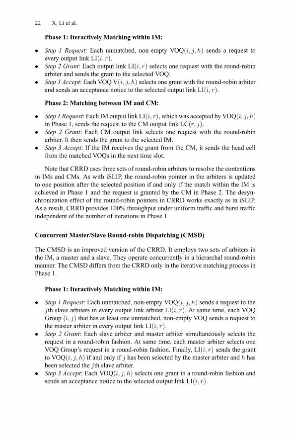
We compare the delay performance of the dispatching algorithms in the MSM archi-tecture and in the single-stage crossbar switch architecture under uniform traffic. Weuse the Clos-network setting = = = 8, which corresponds to a port size of= 64 in the crossbar switch.As shown in Figure 1.12, the average delay of the algorithms in the MSM ar-
chitecture is larger than those in the crossbar switch when load is below 0.5. Thisis because most of the dispatching algorithms in the crossbar switch perform fairlyefficiently under low traffic load. The MSM architecture introduces more contentionpoints in the distributed modules, however, the performance of the architecture isimproved significantly in the heavy load region, as shared memory modules are ef-fectively used.
The randomness-base algorithms, PIM and CD, could only achieve about 60%throughput. All remaining round-robin algorithms can achieve 100% throughput un-der uniform traffic. SRRD has the lowest average delay and is much closer to theperformance of an output-queued switch. This result shows the significant effect ofthe SRR technique in the MSM architecture.
1.4.3 The Bufferless Clos-network Architecture
Switch Model
One disadvantage of the MSM architecture is that the input and output stages areboth composed of shared-memory modules. This results in a memory speedup of
24 X. Li et al.
0 0.1 0.2 0.3 0.4 0.5 0.6 0.7 0.8 0.9 1
10-1
100
101
102
103
Mea
n D
elay
Normalized Load
PIM (Crossbar)iSLIP (Crossbar)SRR (Crossbar)CD (MSM)CRRD (MSM)CMSD (MSM)SRRD (MSM)Output Queued
Figure 1.12. Delay comparison of crossbar and MSM
in each IM and in each OM. In output-queued switches, the memory speedup is= × . Although the speedup of MSM is smaller than that in output-queued
switches, it definitely hinders a switch’s ability to scale up to very large port numbers.In [37], a bufferless Clos-network switching architecture has been proposed.
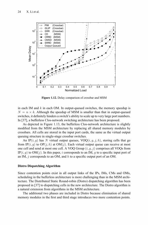
As depicted in Figure 1.13, the bufferless Clos-network architecture is slightlymodified from the MSM architecture by replacing all shared memory modules bycrossbars. All cells are stored in the input port cards, the same as the virtual outputqueuing structure in single-stage crossbar switches.
An IP( ) has virtual output queues, VOQ( ), storing cells that gofrom IP( ) to OP( ) at OM( ). Each virtual output queue can receive at mostone cell and send at most one cell. A VOQ Group ( ) comprises all VOQs fromIP( ) to OM( ). In this paper, corresponds to an IM, to a specific input port ofan IM, corresponds to an OM, and to a specific output port of an OM.
Distro Dispatching Algorithm
Since contention points exist in all output links of the IPs, IMs, CMs and OMs,scheduling in the bufferless architecture is more challenging than in the MSM archi-tecture. The Distributed Static Round-robin (Distro) dispatching algorithm has beenproposed in [37] to dispatching cells in the new architecture. The Distro algorithm isa natural extension from algorithms in the MSM architecture.
The additional two phases are included in Distro because elimination of sharedmemory modules in the first and third stage introduces two more contention points.
Architectures of Internet Switches and Routers 25
CM (r)
CM (k-1)
CM (0)IM (0)
IM (i)
IM (k-1)
VOQ (0,n-1,0,0)
VOQ (0,n-1,k-1,n-1)
IP (0,n-1)
VOQ (0,0,0,0)
VOQ (0,0,k-1,n-1)
IP (0,0)
VOQ (k-1,0,0,0)
VOQ (k-1,0,k-1,n-1)
IP (k-1,0)
VOQ (k-1,n-1,0,0)
VOQ (k-1,n-1,k-1,n-1)
IP (k-1,n-1)
OM (k-1)
OP (k-1,n-1)
OP (k-1,0)
OM (j)
OP ( j, h )
OM (0)
OP (0,n-1)
OP (0,0)
IP ( i, g )
LIM ( i, r ) LCM ( r, j )
CM (r)
CM (k-1)
CM (0)IM (0)
IM (i)
IM (k-1)
VOQ (0,n-1,0,0)
VOQ (0,n-1,k-1,n-1)
IP (0,n-1)
VOQ (0,0,0,0)
VOQ (0,0,k-1,n-1)
IP (0,0)
VOQ (k-1,0,0,0)
VOQ (k-1,0,k-1,n-1)
IP (k-1,0)
VOQ (k-1,n-1,0,0)
VOQ (k-1,n-1,k-1,n-1)
IP (k-1,n-1)
OM (k-1)
OP (k-1,n-1)
OP (k-1,0)
OM (j)
OP ( j, h )
OM (0)
OP (0,n-1)
OP (0,0)
IP ( i, g )
CM (r)
CM (k-1)
CM (0)
CM (r)CM (r)
CM (k-1)CM (k-1)
CM (0)CM (0)IM (0)
IM (i)
IM (k-1)
IM (0)IM (0)
IM (i)IM (i)
IM (k-1)IM (k-1)
VOQ (0,n-1,0,0)
VOQ (0,n-1,k-1,n-1)
IP (0,n-1)
VOQ (0,0,0,0)
VOQ (0,0,k-1,n-1)
IP (0,0)
VOQ (0,n-1,0,0)
VOQ (0,n-1,k-1,n-1)
IP (0,n-1)
VOQ (0,n-1,0,0)
VOQ (0,n-1,k-1,n-1)
VOQ (0,n-1,0,0)VOQ (0,n-1,0,0)
VOQ (0,n-1,k-1,n-1)VOQ (0,n-1,k-1,n-1)
IP (0,n-1)
VOQ (0,0,0,0)
VOQ (0,0,k-1,n-1)
IP (0,0)
VOQ (0,0,0,0)
VOQ (0,0,k-1,n-1)
VOQ (0,0,0,0)VOQ (0,0,0,0)
VOQ (0,0,k-1,n-1)VOQ (0,0,k-1,n-1)
IP (0,0)
VOQ (k-1,0,0,0)
VOQ (k-1,0,k-1,n-1)
IP (k-1,0)
VOQ (k-1,n-1,0,0)
VOQ (k-1,n-1,k-1,n-1)
IP (k-1,n-1)
VOQ (k-1,0,0,0)
VOQ (k-1,0,k-1,n-1)
IP (k-1,0)
VOQ (k-1,0,0,0)
VOQ (k-1,0,k-1,n-1)
VOQ (k-1,0,0,0)VOQ (k-1,0,0,0)
VOQ (k-1,0,k-1,n-1)VOQ (k-1,0,k-1,n-1)
IP (k-1,0)
VOQ (k-1,n-1,0,0)
VOQ (k-1,n-1,k-1,n-1)
IP (k-1,n-1)
VOQ (k-1,n-1,0,0)
VOQ (k-1,n-1,k-1,n-1)
VOQ (k-1,n-1,0,0)VOQ (k-1,n-1,0,0)
VOQ (k-1,n-1,k-1,n-1)VOQ (k-1,n-1,k-1,n-1)
IP (k-1,n-1)
OM (k-1)
OP (k-1,n-1)
OP (k-1,0)
OM (k-1)
OP (k-1,n-1)OP (k-1,n-1)
OP (k-1,0)OP (k-1,0)
OM (j)
OP ( j, h )
OM (j)
OP ( j, h )
OM (0)
OP (0,n-1)
OP (0,0)
OM (0)
OP (0,n-1)OP (0,n-1)
OP (0,0)OP (0,0)
IP ( i, g )IP ( i, g )
LIM ( i, r ) LCM ( r, j )
Figure 1.13. The bufferless Clos-network model
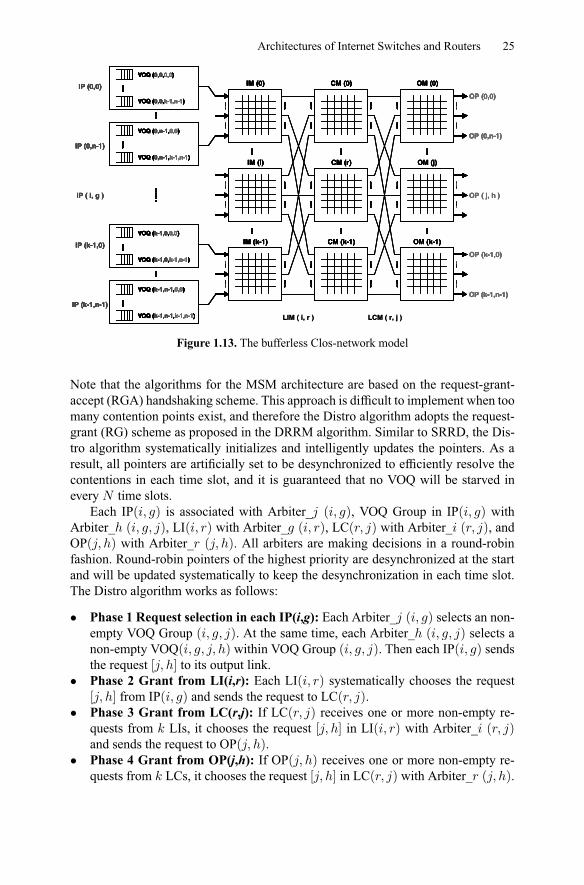
Note that the algorithms for the MSM architecture are based on the request-grant-accept (RGA) handshaking scheme. This approach is difficult to implement when toomany contention points exist, and therefore the Distro algorithm adopts the request-grant (RG) scheme as proposed in the DRRM algorithm. Similar to SRRD, the Dis-tro algorithm systematically initializes and intelligently updates the pointers. As aresult, all pointers are artificially set to be desynchronized to efficiently resolve thecontentions in each time slot, and it is guaranteed that no VOQ will be starved inevery time slots.
Each IP( ) is associated with Arbiter_ ( ), VOQ Group in IP( ) withArbiter_ ( ), LI( ) with Arbiter_ ( ), LC( ) with Arbiter_ ( ), andOP( ) with Arbiter_ ( ). All arbiters are making decisions in a round-robinfashion. Round-robin pointers of the highest priority are desynchronized at the startand will be updated systematically to keep the desynchronization in each time slot.The Distro algorithm works as follows:
• Phase 1 Request selection in each IP(i,g): Each Arbiter_ ( ) selects an non-empty VOQ Group ( ). At the same time, each Arbiter_ ( ) selects anon-empty VOQ( ) within VOQ Group ( ). Then each IP( ) sendsthe request [ ] to its output link.
• Phase 2 Grant from LI(i,r): Each LI( ) systematically chooses the request[ ] from IP( ) and sends the request to LC( ).
• Phase 3 Grant from LC(r,j): If LC( ) receives one or more non-empty re-quests from LIs, it chooses the request [ ] in LI( ) with Arbiter_ ( )and sends the request to OP( ).
• Phase 4 Grant from OP(j,h): If OP( ) receives one or more non-empty re-quests from LCs, it chooses the request [ ] in LC( ) with Arbiter_ ( ).
26 X. Li et al.
0 0.1 0.2 0.3 0.4 0.5 0.6 0.7 0.8 0.9 1
10-1
100
101
102
103
Mea
n D
elay
Normalized Load
iSlip (Crossbar)CRRD (MSM)Distro (Bufferless)
Figure 1.14. Delay comparison with crossbar and multi-stage scheduling algorithms
Finally, OP( ) notifies the IP( ) via the granted path, and the VOQ ( )will send to OP( ) in the next time slot.
As mentioned before, the bufferless Clos-network architecture is very scalablefor port size. There are actually many flexibilities in the configurations. We can eitherscale up the port size by increasing the number of ports per input/output module,or increasing the number of central modules . Note that must be larger than orequal to in order to achieve the non-blocking property in Clos networks.
Performance Evaluation
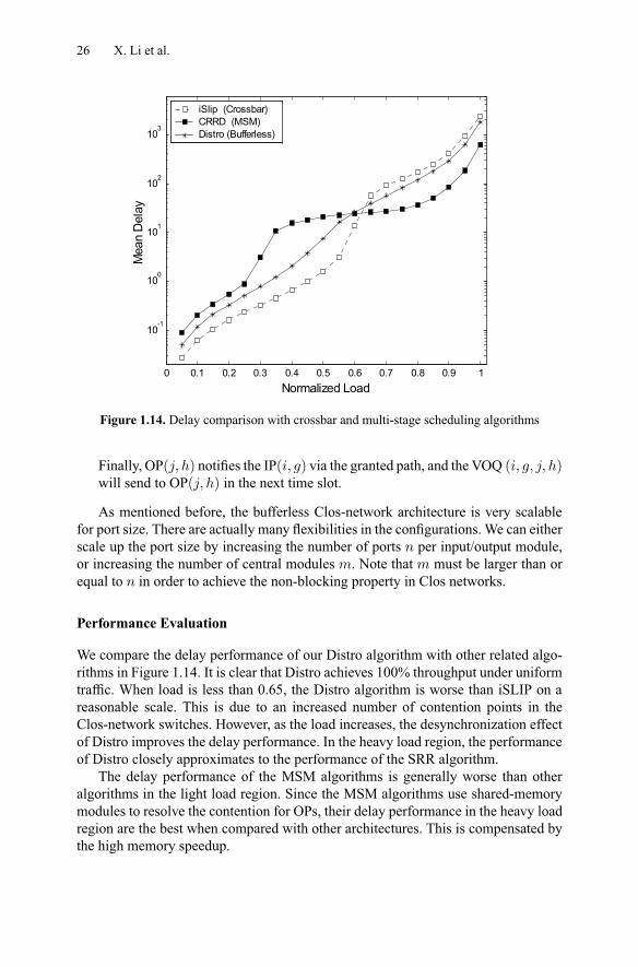
We compare the delay performance of our Distro algorithm with other related algo-rithms in Figure 1.14. It is clear that Distro achieves 100% throughput under uniformtraffic. When load is less than 0.65, the Distro algorithm is worse than iSLIP on areasonable scale. This is due to an increased number of contention points in theClos-network switches. However, as the load increases, the desynchronization effectof Distro improves the delay performance. In the heavy load region, the performanceof Distro closely approximates to the performance of the SRR algorithm.
The delay performance of the MSM algorithms is generally worse than otheralgorithms in the light load region. Since the MSM algorithms use shared-memorymodules to resolve the contention for OPs, their delay performance in the heavy loadregion are the best when compared with other architectures. This is compensated bythe high memory speedup.
Architectures of Internet Switches and Routers 27
0 - 255
Optical SwitchFabric
256 - 511 512 - 767 768 - 1023
Rack
OC-192
O/E Converters
ElectronicLine Cards
OpitcalInterconnects
0 - 255
Figure 1.15. Illustration of a multi-rack switching system (1024× 1024, 4 racks)
1.5 Optical Packet Switching
1.5.1 Multi-rack Hybrid Opto-electronic Switch Architecture
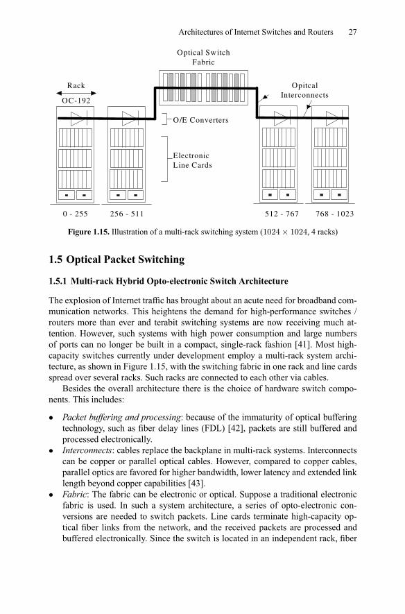
The explosion of Internet traffic has brought about an acute need for broadband com-munication networks. This heightens the demand for high-performance switches /routers more than ever and terabit switching systems are now receiving much at-tention. However, such systems with high power consumption and large numbersof ports can no longer be built in a compact, single-rack fashion [41]. Most high-capacity switches currently under development employ a multi-rack system archi-tecture, as shown in Figure 1.15, with the switching fabric in one rack and line cardsspread over several racks. Such racks are connected to each other via cables.
Besides the overall architecture there is the choice of hardware switch compo-nents. This includes:
• Packet buffering and processing: because of the immaturity of optical bufferingtechnology, such as fiber delay lines (FDL) [42], packets are still buffered andprocessed electronically.
• Interconnects: cables replace the backplane in multi-rack systems. Interconnectscan be copper or parallel optical cables. However, compared to copper cables,parallel optics are favored for higher bandwidth, lower latency and extended linklength beyond copper capabilities [43].
• Fabric: The fabric can be electronic or optical. Suppose a traditional electronicfabric is used. In such a system architecture, a series of opto-electronic con-versions are needed to switch packets. Line cards terminate high-capacity op-tical fiber links from the network, and the received packets are processed andbuffered electronically. Since the switch is located in an independent rack, fiber
28 X. Li et al.
links are used to transfer packets between the line cards and the switch fabric. Itis clear from the above description that the system introduces an additional layerof opto-electronic (O/E) conversions between the interconnect and the switchfabric, which results in high complexity and significantly higher cost. In addi-tion, the central electronic fabric occupies valuable floor space, consumes a lotof power, and poses several reliability problems owing to the large number ofhigh-speed active components.An obvious evolution to this architecture is to try to replace the central electronicfabric with an optical fabric [44, 45, 46, 47, 48]. Optical switch fabrics mayovercome the cost, power, space, and scalability problems that arise in sizingtraditional electrical backplanes into the terabit regime.
To this end, an opto-electronic hybrid switch based on the strengths of both elec-tronics and optics is a practical and viable approach. This architecture uses electron-ics for packet processing/scheduling/buffering and optics for packet transmission andswitching.
1.5.2 Optical Fabrics
The basic premise of optical switch fabrics is their high switching capacities andreduction in O/E conversions. These advantages are significant as there is no needfor lots of expensive high-speed electronics. Furthermore, optical fabrics are cheaperand smaller in physical size. They may also provide potential benefits including scal-ability, high bit rate, and low power consumption. The technologies include opticalmicro-electromechanical systems (MEMS)-based switching [49][50], thermal opti-cal switching [51], electro-optic switching, bubble switches [52], etc. Reference [53]gives a detailed comparison between these optical switching technologies.
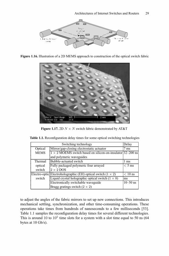
We use optical MEMS fabric as an example. The basic switching elements ofMEMS are tiny micro-actuated free-rotating mirrors as shown in Figure 1.16. Theswitching function is performed by reflection of the light. MEMS has several hundredof these tiny mirrors arranged in arrays and integrated on a silicon chip. The two-dimensional (2D) optical MEMS has mirrors arranged in a crossbar configuration[54]. Figure 1.17 shows a photo of a 2D × switch fabric made by AT&T [55].Collimated light beams propagate parallel to the substrate plane. When a mirror isactivated, it moves into the path of the beam and directs the light to one of the outputsby making a 45 angle with the beam. In general, the ( ) mirror is raised to directlight from the th input fiber to the th output fiber. The mirror is no larger in diameterthan a human hair. Several hundred such mirrors can be built on a chip no larger thana few centimeters square. Since MEMS create so many mirrors on a single chip,the cost per switching element is relatively low. Therefore, MEMS allow low-losslarge-port-count optical switching solutions at very low cost per port.
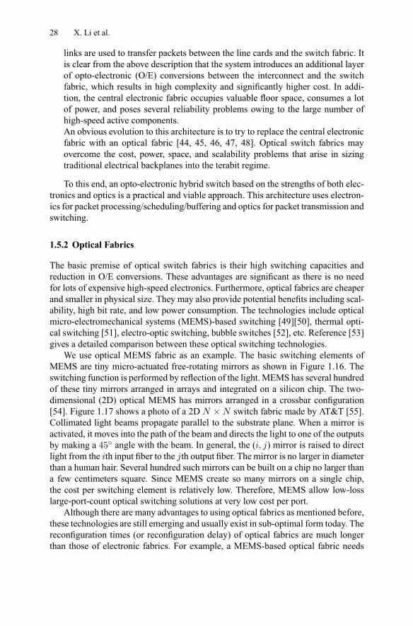
Although there are many advantages to using optical fabrics as mentioned before,these technologies are still emerging and usually exist in sub-optimal form today. Thereconfiguration times (or reconfiguration delay) of optical fabrics are much longerthan those of electronic fabrics. For example, a MEMS-based optical fabric needs
Architectures of Internet Switches and Routers 29
Figure 1.16. Illustration of a 2D MEMS approach to construction of the optical switch fabric
Figure 1.17. 2D × switch fabric demonstrated by AT&T
Table 1.1. Reconfiguration delay times for some optical switching technologies
Switching technology DelayOptical Mirror/gap-closing electrostatic actuator 7 msMEMS 1× 2MOEMS switch based on silicon-on-insulator 32–200 ns
and polymeric waveguidesThermal Bubble-actuated switch 1 msoptical Fully packaged polymeric four arrayed 5 msswitch 2× 2 DOS
Electro-optic Electroholographic (EH) optical switch (1× 2) 10 nsswitch Liquid crystal holographic optical switch (1× 8) ms
Electronically switchable waveguide 10–50 nsBragg gratings switch (2× 2)
to adjust the angles of the fabric mirrors to set up new connections. This introducesmechanical settling, synchronization, and other time-consuming operations. Theseoperations take times from hundreds of nanoseconds to a few milliseconds [53].Table 1.1 samples the reconfiguration delay times for several different technologies.This is around 10 to 105 time slots for a system with a slot time equal to 50 ns (64bytes at 10 Gb/s).
30 X. Li et al.
1.5.3 Reduced Rate Scheduling
As introduced earlier, the scheduling task in all switches is to find a one-to-one bi-partite match between inputs and outputs to switch out the packets, no matter if thefabric is optical or electronic. Generally in each time slot, the electronic switch runsthe scheduling, sets up a new fabric connection, and then transfers the correspondingcells.
However, this slot-by-slot approach is not practical for optical switches. For ex-ample, if the reconfiguration delay equals one time slot, one cell transmission takestwo time slots. One time slot is for scheduling and connection setup (fabric recon-figuration), the second time slot is for actual transmission. In other words, only halfof the fabric bandwidth is used for cell transmission (which is effective bandwidth);while the other half is wasted for reconfiguration. For a switch which transfers 64Bpackets at a 40 Gb/s line rate and suffers a 100 ns reconfiguration delay, the effectivebandwidth is as low as 10%. If the reconfiguration delay is not addressed by a properscheduling scheme, it can severely cripple the performance of optical switches. It isclear that the scheduling rate must be reduced to compensate for the reconfigurationdelay. Each schedule holds for some time rather than changing at every time slot.
The reduced rate scheduling is not a simple extension of scheduling algorithmsintroduced in Section 1.2. It has been proven that the scheduling problem for opticalswitches with reconfiguration delay is NP-hard [48]. Currently, most of the reducedrate scheduling algorithms use the time slot assignment (TSA) approach [56, 57, 58,48] and provide heuristic solutions.
1.5.4 Time Slot Assignment (TSA) Approach
The TSA-type of algorithm periodically accumulates incoming traffic and maps thisbatch to a set of switch configurations. The objective of TSA scheduling in an opticalswitch is to find a set of fabric configurations (or schedules) and their respectiveholding time, to switch out all of the accumulated traffic, and to maximize the fabricutilization. In other words, this is equivalent to minimizing the total transmissionmakespan, which includes the time spent in transmitting traffic and the time spent inreconfiguring the fabric. This is proved to be NP-hard under non-zero reconfigurationdelay [48]. All algorithms introduced here are heuristic.
Scheduling Scheme
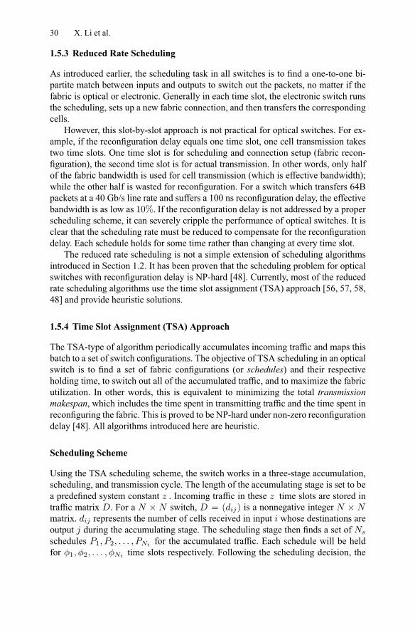
Using the TSA scheduling scheme, the switch works in a three-stage accumulation,scheduling, and transmission cycle. The length of the accumulating stage is set to bea predefined system constant . Incoming traffic in these time slots are stored intraffic matrix . For a × switch, = ( ) is a nonnegative integer ×matrix. represents the number of cells received in input whose destinations areoutput during the accumulating stage. The scheduling stage then finds a set ofschedules 1 2 for the accumulated traffic. Each schedule will be heldfor 1 2 time slots respectively. Following the scheduling decision, the
Architectures of Internet Switches and Routers 31
5 1 21 3 20 4 3
42
4
2
0
1
2
11
12 1
Traffic M atrix
41 =ΦP1
22 =ΦP2
23 =ΦP3
14 =ΦP4
1Φ 2Φ 3Φ 4Φδ δ δ δ
1. Accumulation stage
2. Scheduling stage(Ns schedules
with respective holding times)
3. Transmission stage
Covering cost (or transfer makespan)
Reconfigurationsub-stage
Traffic-sendingsub-stage
InputOutput
Figure 1.18. TSA scheduling example
transmission stage sets up the fabric and switches out the traffic repeatedly until allpackets are sent out. The transmission makespan is equal to
P=1 + . Figure
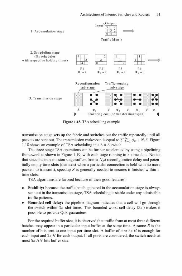
1.18 shows an example of TSA scheduling in a 3× 3 switch.The three-stage TSA operations can be further accelerated by using a pipelining
framework as shown in Figure 1.19, with each stage running in time slots. Noticethat since the transmission stage suffers from a reconfiguration delay and poten-tially empty time slots (that exist when a particular connection is held with no morepackets to transmit), speedup is generally needed to ensures it finishes withintime slots.
TSA algorithms are favored because of their good features:
• Stability: because the traffic batch gathered in the accumulation stage is alwayssent out in the transmission stage, TSA scheduling is stable under any admissibletraffic patterns.
• Bounded cell delay: the pipeline diagram indicates that a cell will go throughthe switch within 3 slot times. This bounded worst cell delay (3 ) makes itpossible to provide QoS guarantees.
For the required buffer size, it is observed that traffic from at most three differentbatches may appear in a particular input buffer at the same time. Assume B is thenumber of bits sent to one input per time slot. A buffer of size 3 is enough foreach input and 2 for each output. If all ports are considered, the switch needs atmost 5 bits buffer size.
32 X. Li et al.
A
A
A
B
B
B
Stages
1. A ccum ulation
2. Scheduling
3. T ransm ission
T 2T 3T 4T Tim e
C ell D elay
Figure 1.19. Pipelined TSA execution with two traffic batches
1.5.5 DOUBLE Algorithm
Early TSA algorithms assume the reconfiguration delay to be zero [56] or infinite[57] for simplicity. However, the extreme assumptions on reconfiguration delay areno longer practical in optical switching systems. A recent DOUBLE algorithm [58]considers scheduling under moderate reconfiguration delays. It performs better thanalgorithms with extreme assumptions under a large spectrum of reconfiguration delayvalues [58].
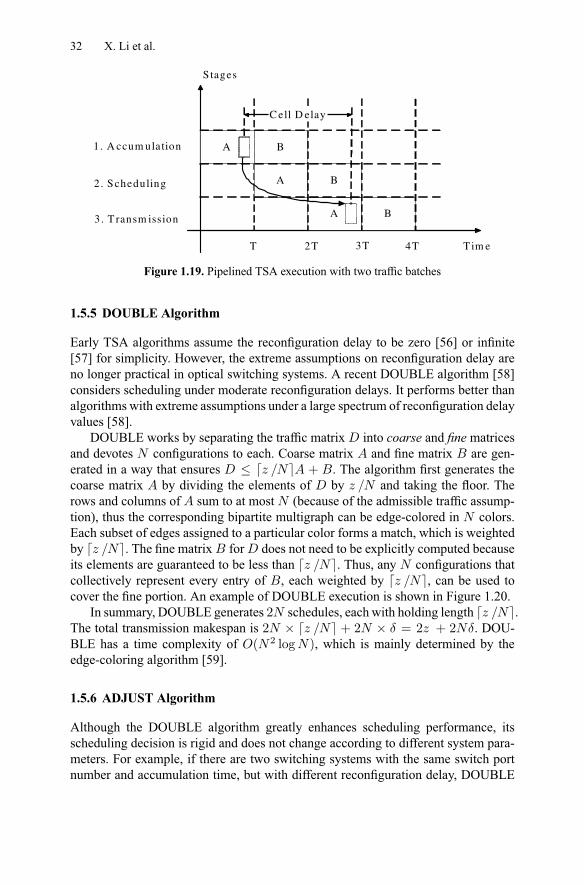
DOUBLE works by separating the traffic matrix into coarse and fine matricesand devotes configurations to each. Coarse matrix and fine matrix are gen-erated in a way that ensures d e + . The algorithm first generates thecoarse matrix by dividing the elements of by and taking the floor. Therows and columns of sum to at most (because of the admissible traffic assump-tion), thus the corresponding bipartite multigraph can be edge-colored in colors.Each subset of edges assigned to a particular color forms a match, which is weightedby d e. The fine matrix for does not need to be explicitly computed becauseits elements are guaranteed to be less than d e. Thus, any configurations thatcollectively represent every entry of , each weighted by d e, can be used tocover the fine portion. An example of DOUBLE execution is shown in Figure 1.20.
In summary, DOUBLE generates 2 schedules, each with holding length d e.The total transmission makespan is 2 × d e + 2 × = 2 + 2 . DOU-BLE has a time complexity of ( 2 log ), which is mainly determined by theedge-coloring algorithm [59].
1.5.6 ADJUST Algorithm
Although the DOUBLE algorithm greatly enhances scheduling performance, itsscheduling decision is rigid and does not change according to different system para-meters. For example, if there are two switching systems with the same switch portnumber and accumulation time, but with different reconfiguration delay, DOUBLE
Architectures of Internet Switches and Routers 33
Figure 1.20. Example of the DOUBLE algorithm
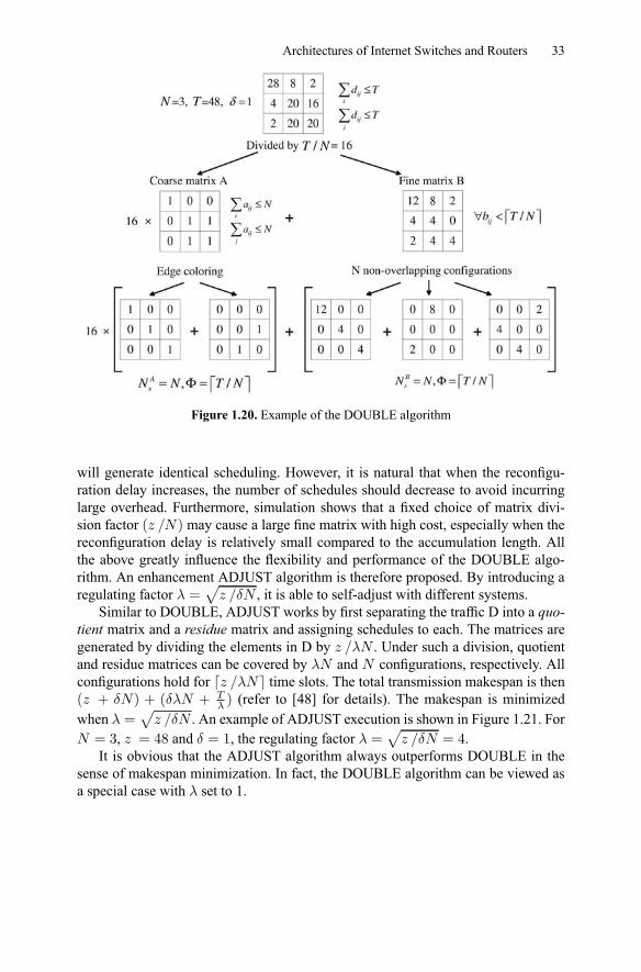
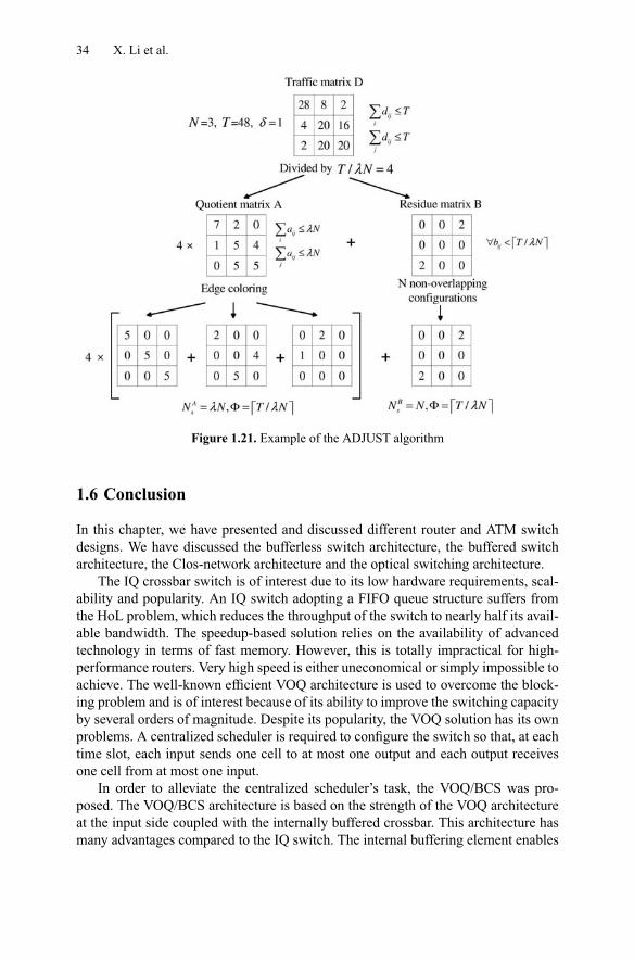
will generate identical scheduling. However, it is natural that when the reconfigu-ration delay increases, the number of schedules should decrease to avoid incurringlarge overhead. Furthermore, simulation shows that a fixed choice of matrix divi-sion factor ( ) may cause a large fine matrix with high cost, especially when thereconfiguration delay is relatively small compared to the accumulation length. Allthe above greatly influence the flexibility and performance of the DOUBLE algo-rithm. An enhancement ADJUST algorithm is therefore proposed. By introducing aregulating factor =
p, it is able to self-adjust with different systems.
Similar to DOUBLE, ADJUST works by first separating the traffic D into a quo-tient matrix and a residue matrix and assigning schedules to each. The matrices aregenerated by dividing the elements in D by . Under such a division, quotientand residue matrices can be covered by and configurations, respectively. Allconfigurations hold for d e time slots. The total transmission makespan is then( + ) + ( + ) (refer to [48] for details). The makespan is minimizedwhen =
p. An example of ADJUST execution is shown in Figure 1.21. For
= 3, = 48 and = 1, the regulating factor =p
= 4.It is obvious that the ADJUST algorithm always outperforms DOUBLE in the
sense of makespan minimization. In fact, the DOUBLE algorithm can be viewed asa special case with set to 1.
34 X. Li et al.
Figure 1.21. Example of the ADJUST algorithm
1.6 Conclusion
In this chapter, we have presented and discussed different router and ATM switchdesigns. We have discussed the bufferless switch architecture, the buffered switcharchitecture, the Clos-network architecture and the optical switching architecture.
The IQ crossbar switch is of interest due to its low hardware requirements, scal-ability and popularity. An IQ switch adopting a FIFO queue structure suffers fromthe HoL problem, which reduces the throughput of the switch to nearly half its avail-able bandwidth. The speedup-based solution relies on the availability of advancedtechnology in terms of fast memory. However, this is totally impractical for high-performance routers. Very high speed is either uneconomical or simply impossible toachieve. The well-known efficient VOQ architecture is used to overcome the block-ing problem and is of interest because of its ability to improve the switching capacityby several orders of magnitude. Despite its popularity, the VOQ solution has its ownproblems. A centralized scheduler is required to configure the switch so that, at eachtime slot, each input sends one cell to at most one output and each output receivesone cell from at most one input.
In order to alleviate the centralized scheduler’s task, the VOQ/BCS was pro-posed. The VOQ/BCS architecture is based on the strength of the VOQ architectureat the input side coupled with the internally buffered crossbar. This architecture hasmany advantages compared to the IQ switch. The internal buffering element enables
Architectures of Internet Switches and Routers 35
totally distributed VOQs arbitration and the scheduler is not centralized anymore.The distributed nature of the arbitration improves the switching performance by sev-eral orders of magnitude. By means of computer simulation, we showed the improve-ment of the VOQ/BCS over the IQ switch. Furthermore, the VOQ/BCS doesn’t needany additional cost such as speedup.
In an attempt at scalability, single-stage switching techniques are considered tobe inherently limited by their quadratic complexity. The Clos-network architecture iswidely recognized as a very scalable architecture for high-speed switching systems.So far, only limited success has been reported in the design of practical distributedscheduling schemes for the Clos-network. The ATLANTA switch with MSM archi-tecture is an example of a commercially successful Clos-network switch. However, itnecessitates internal bandwidth speedup. Recently, the CRRD and CMSD algorithmshave been proposed in order to overcome the throughput limitation and implemen-tation complexity problem. Based on the static round-robin technique, SRRD hasbeen proposed to reduce the delay performance and deduce the hardware complexity.However, due to the memory speedup up problem in the shared memory modules, theMSM arrangement of the Clos-network switches hinder the scalability to very largeport size. A bufferless Clos-network architecture has been proposed in which theshared memory modules are replaced by bufferless crossbar switching components.Although it requires a greater communication overhead among distributed modules,the bufferless Clos-network architecture is an efficient way to solve the scalabilityproblem in switching systems.
One attractive direction in building scalable switches and routers is to adopt opti-cal switching techniques. However, a main challenge remains in efficiently queuingthe packets in the optical domain. The techniques (i.e. fiber delay lines) are not yetmature enough to support such functionalities. A viable solution is to have a hybridswitch architecture, with electronic buffers and optical fabrics. Having optical fab-rics provides more scalability and higher switching speed over the electronic coun-terparts.
We are still facing many challenging requirements pertaining to the design ofscalable and high-performance routers. In summary, the new generation of switchesand router should first be highly scalable in port number and interface speed. More-over, routers have to offer many services to meet today’s customer needs such asguaranteed delay, bounded delay variation, minimal packet loss and controlled ac-cess. Finally, a router has to be cost effective.
36 X. Li et al.
References
1. M. Karol, M. Hluchyj, and S. Morgan. Input versus output queuing on a space divisionswitch. IEEE Transaction on Communications, 35(12):1347–1356, 1987.
2. N. McKeown. islip: A scheduling algorithm for input-queued switches. IEEE/ACMTransaction On Networking, 7(2):188–201, Apr 1999.
3. M. Nabeshima. Performance evaluation of combined input-and crosspoint-queued switch.IEICE Transaction on Communicaitons, E83-B(3), Mar 2000.
4. S. Nojima, E. Tsutsui, H. Fukuda, and M. Hashimmoto. Integrated packet network usingbus matrix. IEEE Journal on Selected Areas in Communications, 5(8):1284–1291, Oct1987.
5. L. Mhamdi, M. Hamdi, C. Kachris, S. Wong, and S. Vassiliadis. High-performanceswitching based on buffered crossbar fabrics. To appear in Computer Networks Journal.
6. T. Cheney, J.A. Fingerhurt, M. Flucke, and J.S. Turner. Design of a gigabit atm switch.INFOCOM, pages 2–11, Apr 1997.
7. F.M. Chiussi, J.G. Kneuer, and V.P. Kumar. Low-cost scalable switching solutions forbroadband networking: the atlanta architecture and chipset. IEEE Communication Mag-azine, 35(3):44–53, Dec 1997.
8. A. Demers, S. Keshav, and S. Shenker. Analysis and simulation of a fair queuing algo-rithm. Inernetworking: Research and Experience, 1(1):3–26, Sep 1990.
9. H. Zhang. Service disciplines for guaranteed performance service in packet-switchingnetworks. Proceeding of the IEEE, 83(10):1374–96, Oct 1995.
10. S. T. Chuang, A. Goel, N. Mckeown, and B. Prabhakar. Matching output queueing witha combined input output queued switch. INFOCOM, pages 1169–1178, Apr 1999.
11. S. Y. Li. Theory of periodic contention and its application to packet switching. INFO-COM, pages 320–325, 1998.
12. N. McKeown, V. Anantharam, and J. Walrand. Achieving 100% throughput in an input-queued switch. INFOCOM, pages 296–302, Mar 1996.
13. A. Mekkittikul and N. McKeown. A starvation-free algorithm for achieving 100%throughput in an input-queued switch. ICCCN, pages 226–231, Oct 1996.
14. A. Mekkittikul and N. McKeown. A practical scheduling algorithm to achieve 100%throughput in input-queued switches. INFOCOM, pages 792–799, Apr 1998.
15. T. Anderson, S. Owicki, J. Saxe, and C. Thacker. High speed switch scheduling for localarea networks. ACM Transaction on Computer Systems, 11(4):319–352, Nov 1993.
16. D. N. Serpanos and P. I. Antoniadis. FIRM: A class of distributed scheduling algorithmsfor high-speed atm switches with multiple input queues. INFOCOM, pages 548–555, Mar2000.
17. L. Tassiulas. Linear complexity algorithms for maximum throughput in radio networksand input queued switches. INFOCOM, 2:533–539, Mar 1998.
18. P. Giaccone, B. Prabhakar, and D. Shah. Towards simple, high-performance schedulersfor high-aggregate bandwidth switches. INFOCOM, pages 1160–1169, Jun 2002.
19. D. Gale and L. S. Shapley. College admissions and the stability of marriage. AmericanMathematical Monthly, 69(9):9–14, 1962.
20. I. Stoica and H. Zhang. Exact emulation of an output queueing switch by a combinedinput output queueing switch. IEEE/IFIP IWQoS, pages 218–224, May 1998.
21. P. Krishna, N. S. Patel, A. Charny, and R. J. Simcoe. On the speedup required forwork-conserving crossbar switches. IEEE Journal on Selected Areas in Communications,17(6):1057–1066, Jun 1999.
22. R. Bakka and M. Dieudonne. Switching circuits for digital packet switching network.United States Patent 4,314,367, Feb 1982.
Architectures of Internet Switches and Routers 37
23. M. Katevenis. Fast switching and fair control of congested flow in broad-band networks.IEEE Journal on Selected Areas in Communications, 5(8):1315–1326, Oct 1987.
24. A. K. Gupta, L. O. Barbosa, and N. D. Gorganas. 16 × 16 limited intermediate bufferswitch module for atm networks for b-isdn. GLOBECOM, pages 939–943, Dec 1991.
25. M. Lin and N. Mckeown. The throughput of a buffered crossbar switch. IEEE Commu-nications Letters, 9(5):465–467, May 2005.
26. S. Chuang, S. Iyer, and N. McKeown. Practical algorithms for performance guarantees inbuffered crossbars. INFOCOM, pages 981–991, Mar 2005.
27. F. Abel, C. Minkenberg, R. Luijten, M. Gusat, and I. Iliadis. A four-terabit packet switchsupporting long round-trip times. IEEE Micro Magazine, 23(1):10–24, Jan/Feb 2003.
28. R. Rojas-Cessa, E. Oki, Z. Jing, and H. J. Chao. CIXB-1: Combined input one-cell-crosspoint buffered switch. HPSR, pages 324–329, May 2001.
29. R. Rojas-Cessa, E. Oki, Z. Jing, and H. J. Chao. CIXB-K: Combined input-crosspoint-output buffered packet switch. GLOBECOM, pages 2654–2660, Nov 2001.
30. D. Stephann and H. Zhang. Implementing distributed packet fair queuing in a scalableswitch architecture. INFOCOM, pages 282–290, Apr 1998.
31. M. Katevenis and G. Passas. Variable-size multipacket segments in buffered crossbar(CICQ) architectures. ICC, pages 999–1004, May 2005.
32. L. Mhamdi and M. Hamdi. Output queued switch emulation by a one-cell-internallybuffered crossbar switch. GLOBECOM, 7:3688–3693, Dec 2003.
33. B. Magill, C. Rohrs, and R. Stevenson. Output-queued switch emulation by fabrics withlimited memory. IEEE Journal on Selected Areas in Communications, May:606–615,2003.
34. A. Mekkittikul. Scheduling Non-Uniform Traffic In High Speed Packet Switches AndRouters. PhD thesis, Stanford University, Nov 1998.
35. L. Mhamdi and M. Hamdi. Practical scheduling algorithms for high-performance packetswitches. ICC, pages 1659–1663, May 2003.
36. L. Mhamdi and M. Hamdi. MCBF: A high-performance scheduling algorithm for in-ternally buffered crossbar switches. IEEE Communications Letters, 7(9):451–453, Sep2003.
37. K. Pun and M. Hamdi. Distro: A distributed static round-robin scheduling algorithm forbufferless clos-network switches. GLOBECOM, Nov 2002.
38. F.M. Chiussi and A. Francini. A distributed scheduling architecture for scalable packetswitches. IEEE Journal on Selected Areas in Communications, 18(12):2665–2683, Dec2000.
39. E. Oki, Z. Jing, R. Rojas-Cessa, and J. Chao. Concurrent round-robin dispatching schemein a clos-network switch. ICC, 1:107–111, Jun 2001.
40. K. Pun and M. Hamdi. Static round-robin dispatching schemes for clos-network switches.HPSR, pages 329–333, May 2002.
41. C. Minkenberg, R. P. Luijten, F. Abel, W. Denzel, and M. Gusat. Current issues in packetswitch design. ACM SIGCOMM Comput. Commun. Review, 33:119–124, 2003.
42. F. Masetti, P. Gavignet-Morin, D. Chiaroni, and G. Da Loura. Fiber delay lines opticalbuffer for ATM photonic switching applications. In Proc. of INFOCOM, pages 935–942,April 1993.
43. L. A. Buckman, K. S. Giboney, J. Straznicky, J. Simon, S. W. Corzine, X. J. Zhang,A. J. Schmit, and D. W. Dolfi. Parallel optical interconnects. In Proc. Conf. Lasers andElectro-Optics (CLEO), pages 535–536, San Francisco, CA, May 2000.
44. S. Bregni, A. Pattavina, and G. Vegetti. Architectures and performance of AWG-basedoptical switching nodes for IP networks. IEEE J. Select. Areas Commun., 21:1113–1121,September 2003.
38 X. Li et al.
45. H. J. Chao, K. L. Deng, and Z. Jing. Petastar: a petabit photonic packet switch. IEEE J.Select. Areas Commun., 21:1096– 1112, September 2003.
46. L. Dittmann, C. Develder, D. Chiaroni, F. Neri, F. Callegati, W. Koerber, A. Stavdas,M. Renaud, A. Rafel, J. Sole-Pareta, Cerroni, N. Leligou, L. Dembeck, B. Mortensen,M. Pickavet, N. Le Sauze, M. Mahony, B. Berde, and G. Eilenberger. The European ISTproject DAVID: a viable approach toward optical packet switching. IEEE J. Select. AreasCommun., 21:1026–1040, September 2003.
47. K. Kar, D. Stiliadis, T. V. Lakshman, and L. Tassiulas. Scheduling algorithms for opticalpacket fabrics. IEEE J. Select. Areas Commun., 21:1143–1155, September 2003.
48. X. Li and M. Hamdi. On scheduling optical packet switches with reconfiguration delay.IEEE J. Select. Areas Commun., 21:1156–1164, September 2003.
49. P. B. Chu, S. S. Lee, and S. Park. MEMS: the path to large optical crossconnects. IEEECommun. Mag., 40:80–87, 2002.
50. Tze-Wei Yeow, K. L. E. Law, and A. Goldenberg. MEMS optical switches. IEEE Com-mun. Mag., pages 158–163, November 2001.
51. M. Hoffman, P. Kopka, and E. Voges. Thermooptical digital switch arrays in silica onsilicon with defined zero voltage state. J. Lightwave Technol., pages 395–400, March1998.
52. J. E. Fouquet, S. Venkatesh, M. Troll, D. Chen, H. F. Wong, , and P. W. Barth. A compact,scalable cross-connect switch using total internal reflection due to thermally-generatedbubbles. In Proc. IEEE/LEOS Annu. Meeting, pages 169–170, Orlando, FL, May 1988.
53. X. H. Ma and G. H. Kuo. Optical switching technology comparison: optical MEMS vs.other technologies. IEEE Commun. Mag., 41:S16–S23, 2003.
54. P. D. Dobbelaere, K. Falta, S. Gloeckner, and S. Patra. Digital MEMS for optical switch-ing. IEEE Commun. Mag., 40:88–95, 2002.
55. L. Y. Lin, E. L. Goldstein, and R. W. Tkach. Free-space micromachined optical switchesfor optical networking. IEEE J. Select. Topics Quantum Electron., 5:4–9, 1999.
56. T. Inukai. An efficient SS/TDMA time slot assignment algorithm. IEEE Trans. Commun.,27:1449–1455, October 1979.
57. I. S. Gopal and C. K. Wong. Minimizing the number of switchings in an SS/TDMAsystem. IEEE Trans. Commun., 33:497–501, June 1985.
58. B. Towles and W. J. Dally. Guaranteed scheduling for switches with configuration over-head. IEEE/ACM Trans. Networking, 11:835–847, October 2003.
59. R. Cole and J. Hopcroft. On edge coloring bipartite graphs. SIAM J. on Comput., 11:540–546, August 1982.


![Manual redes routers y switches [cisco]](https://img.pdfslide.us/doc/110x75/546cde1aaf7959e91e8b6cb7/manual-redes-routers-y-switches-cisco-5584ac294e51c.jpg)