Embed Size (px)
Citation preview
C-130 Propeller BalancingUsing the Honeywell VXP
Chris deLongSr. Manager CBM Technical Sales
Honeywell Aerospace(505) 828-5492
Guy BreaultDirector of Technical Solutions
Derco Aerospace(414) 371-3542
Why Measure Vibration?
• Vibrations are created by the mechanical functions of the propeller, transmission, and engine systems and the aerodynamics effects on the aircraft fuselage.
• The overall vibration level felt is influenced by many individual frequencies of the various components and combinations thereof.
Why Measure Vibration?(con’t)
• With all these frequencies creating their own unique vibration, it sometimes becomes difficult for the maintainer and flight crew to distinguish between what is normal and what is abnormal and requires correction.
• Vibration analysis is a tool that the maintainer needs to become experienced in using.
Why Measure Vibration?(con’t)
• Common causes of a excessive vibration include:– Unbalanced and misaligned propellers (micro
adjustment) – Material defects (improper manufacturing)– External forces (winds, heavy payload)
• Propeller driven aircraft vibrate constantly in flight– As with any rotating machinery
Why Measure Vibration?(con’t)
• Unmonitored vibrations can lead to fatigue and damage– Propeller leaks, Gearbox wear, Turbine cracking
• Many airframe and mission related modifications– All modifications affect aircraft vibrations differently– Increasing stress levels on airframe structure– Greater stresses on dynamic components
Why Measure Vibration?(con’t)
• Vibration measurement direction:– Vertical, Lateral and Fore/Aft
Why Balance?
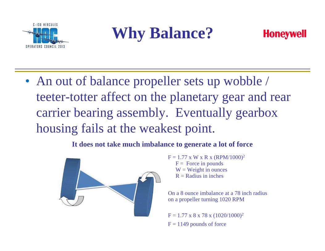
• An out of balance propeller sets up wobble / teeter-totter affect on the planetary gear and rear carrier bearing assembly. Eventually gearbox housing fails at the weakest point.
F = 1.77 x W x R x (RPM/1000)2
F = Force in poundsW = Weight in ouncesR = Radius in inches
On a 8 ounce imbalance at a 78 inch radius on a propeller turning 1020 RPM
F = 1.77 x 8 x 78 x (1020/1000)2
F = 1149 pounds of force
It does not take much imbalance to generate a lot of force
What Does It All Mean?
• Propeller balance procedures can identify internal faults in the propeller assembly that can lead to catastrophic gearbox failure
• The inability to balance a propeller is an indication of a mechanical problem
What Does It All Mean?(con’t)
• Large differences in vibration amplitudes from HSGI to 7000 lbs of torque indicate aerodynamic imbalance. If left uncorrected excessive wear and potential gearbox failure will result
• Deferring and/or delaying propeller balance can have dire consequences
And The Results Can Be Devastating...
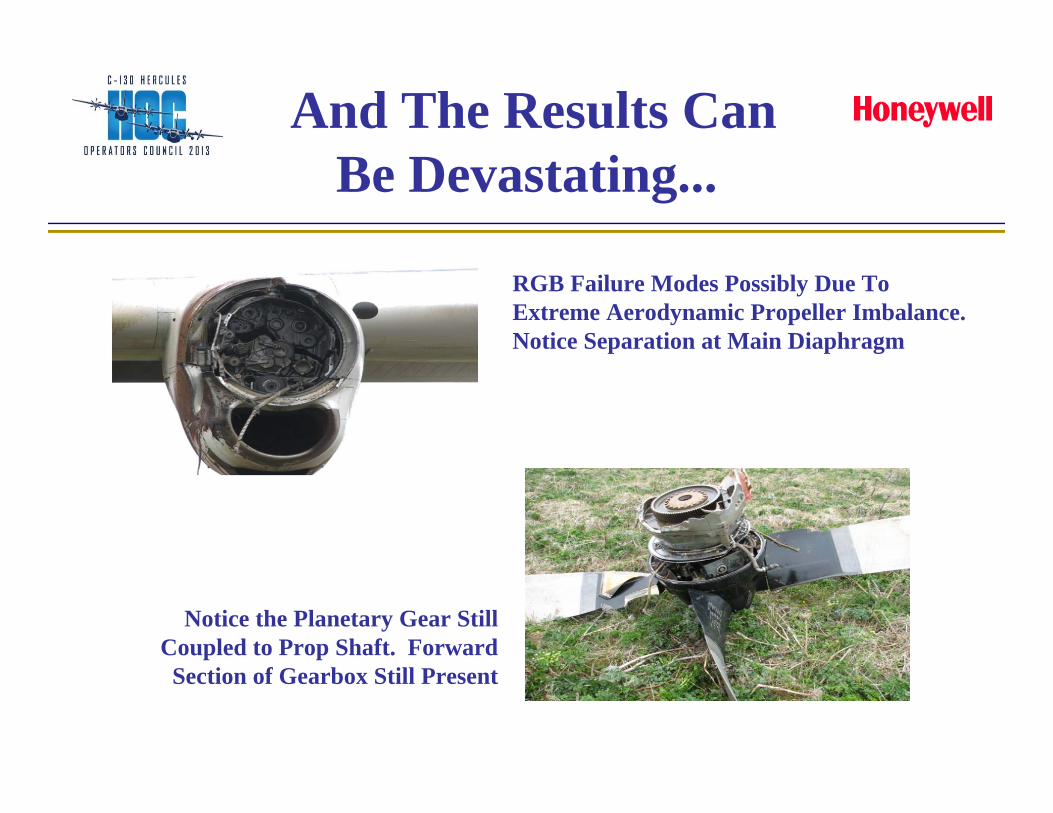
Notice the Planetary Gear Still Coupled to Prop Shaft. Forward Section of Gearbox Still Present
RGB Failure Modes Possibly Due To Extreme Aerodynamic Propeller Imbalance.Notice Separation at Main Diaphragm
C-130 8500C Balancer isNo Longer Available
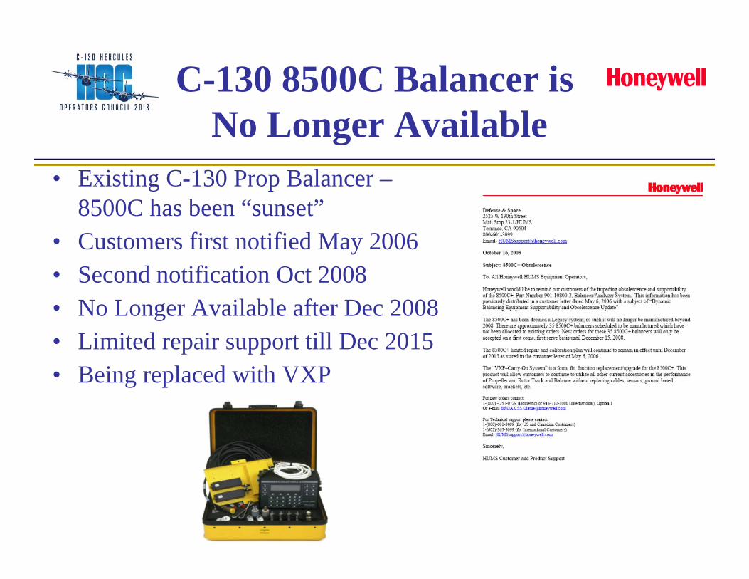
• Existing C-130 Prop Balancer –8500C has been “sunset”
• Customers first notified May 2006• Second notification Oct 2008• No Longer Available after Dec 2008• Limited repair support till Dec 2015• Being replaced with VXP
USAF IssuedMaintenance Advisory
FROM: 330 ACSG ROBINS AFB GA//CLSUBJECT: MAINTENANCE ADVISORY, Transition from Chadwick – Helmuth (C-H) 8500C Equipment to Honeywell VXP for C-130 Engine Health Management (EHM) Tasks1. THE PURPOSE OF THIS MESSAGE IS TO NOTIFY ALL UNITS OF THE transition from the C-H 8500C to
the Honeywell VXP for all EHM tasks on all C-130 aircraft except the C-130J. These EHM tasks include all of the propeller balance, engine signature, torquemeter runout, turbine seal break in, and related tasks in the 1C-130H-2-71JG-00-3.
2. BACKGROUND. a. Units have been using the (C-H) 8500C Balancer/Analyzer for various C-130 EHM tasks since the early 1990’s.
The 8500C has been in use since the early 1980’s and units have had reliability and supportability issues for the last several years. Honeywell bought out C-H in the late 1990’s and declared the 8500C obsolete in December 2008. Limited repair support is available through 2015.
b. The EHM tasks that the C-130 community uses the current C-H 8500 for requires a family of peripheral equipment, cable kits, and aircraft modifications which the C-130 community has invested tens of millions of dollars to procure. The Honeywell VXP was developed as the replacement for the C-H 8500 and is able to use all of the existing peripheral equipment and aircraft modifications with minor changes to the cable kits.
c. The VXP program office (642 CBSG) completed a Val/Ver of the VXP at Kirtland AFB in September 2009 and has received an NSN for both the VXP and the associated kit for the VXP.
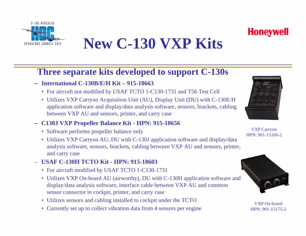
New C-130 VXP Kits
Three separate kits developed to support C-130s– International C-130B/E/H Kit – 915-18663
• For aircraft not modified by USAF TCTO 1-C130-1731 and T56 Test Cell • Utilizes VXP Carryon Acquisition Unit (AU), Display Unit (DU) with C-130E/H
application software and display/data analysis software, sensors, brackets, cabling between VXP AU and sensors, printer, and carry case
– C130J VXP Propeller Balance Kit - HPN: 915-18656• Software performs propeller balance only • Utilizes VXP Carryon AU, DU with C-130J application software and display/data
analysis software, sensors, brackets, cabling between VXP AU and sensors, printer, and carry case
– USAF C-130H TCTO Kit - HPN: 915-18603• For aircraft modified by USAF TCTO 1-C130-1731• Utilizes VXP On-board AU (airworthy), DU with C-130H application software and
display/data analysis software, interface cable between VXP AU and common sensor connector in cockpit, printer, and carry case
• Utilizes sensors and cabling installed to cockpit under the TCTO• Currently set up to collect vibration data from 4 sensors per engine
VXP On-boardHPN: 901-15175-2
VXP CarryonHPN: 901-15160-2
AU
• Utilizes proven 8500C+ Smart Charts for balancing and analysis procedures
• Uses all existing 8500C+ cables and accessories• Reduced kit cost – less LRUs• Designed and tested to meet demanding
environmental requirements• Complete vibration management and control
system– Acquires, processes, and records data at prescribed
intervals
System Benefits
• Reduced time and rapid return on investment– Fast data collection: simultaneous 4 vibration, mag
pickup, and track data collection– No data collected will be lost due to power interrupts
or flight tests– Progressive solutions, based on data collected– Solutions can be edited and VXP will give predictions
based on adjustments– Immediate feedback of vibration exceedance
System Benefits(con’t)
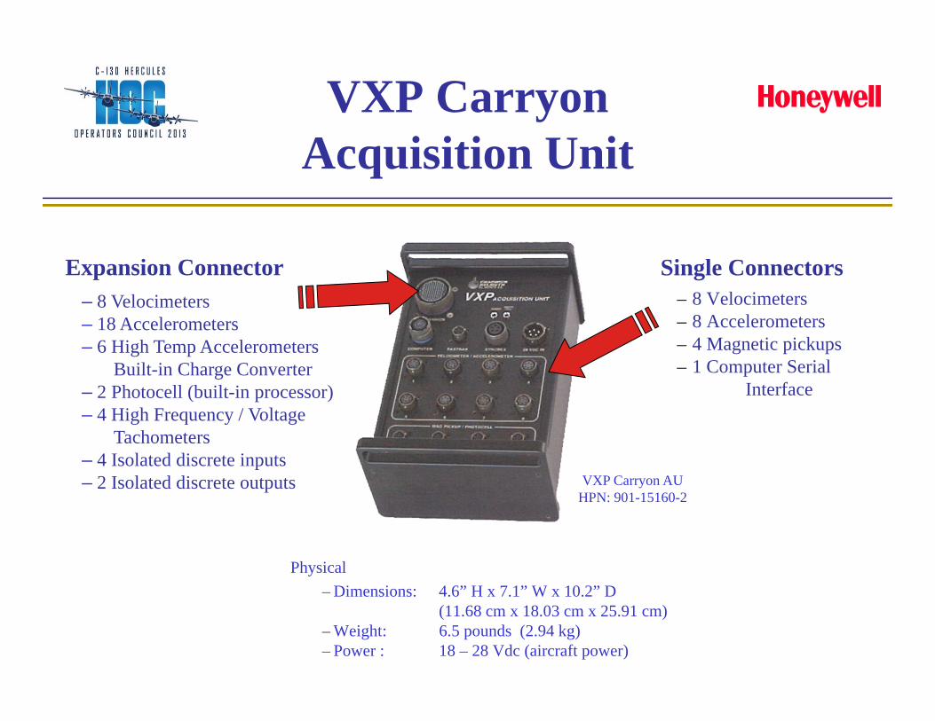
VXP Carryon Acquisition Unit
Single Connectors– 8 Velocimeters– 8 Accelerometers– 4 Magnetic pickups– 1 Computer Serial
Interface
Physical– Dimensions: 4.6” H x 7.1” W x 10.2” D
(11.68 cm x 18.03 cm x 25.91 cm) – Weight: 6.5 pounds (2.94 kg) – Power : 18 – 28 Vdc (aircraft power)
Expansion Connector– 8 Velocimeters– 18 Accelerometers– 6 High Temp Accelerometers
Built-in Charge Converter– 2 Photocell (built-in processor)– 4 High Frequency / Voltage
Tachometers– 4 Isolated discrete inputs– 2 Isolated discrete outputs VXP Carryon AU
HPN: 901-15160-2
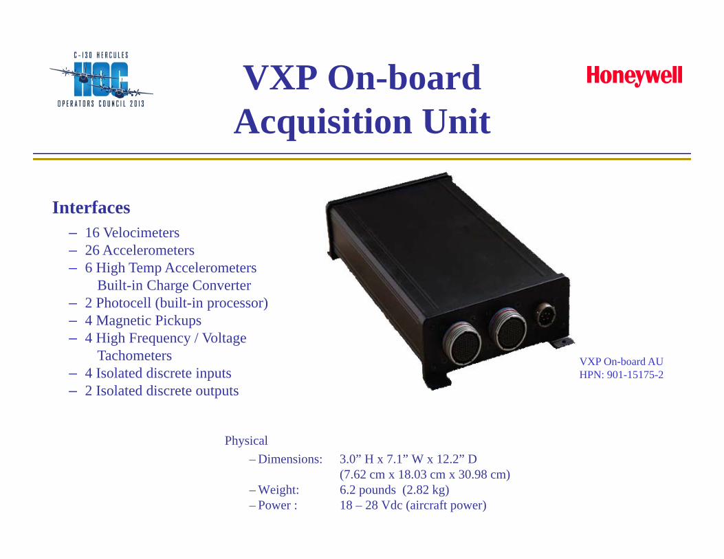
VXP On-board Acquisition Unit
Interfaces– 16 Velocimeters– 26 Accelerometers– 6 High Temp Accelerometers
Built-in Charge Converter– 2 Photocell (built-in processor)– 4 Magnetic Pickups– 4 High Frequency / Voltage
Tachometers– 4 Isolated discrete inputs– 2 Isolated discrete outputs
Physical– Dimensions: 3.0” H x 7.1” W x 12.2” D
(7.62 cm x 18.03 cm x 30.98 cm) – Weight: 6.2 pounds (2.82 kg) – Power : 18 – 28 Vdc (aircraft power)
VXP On-board AUHPN: 901-15175-2
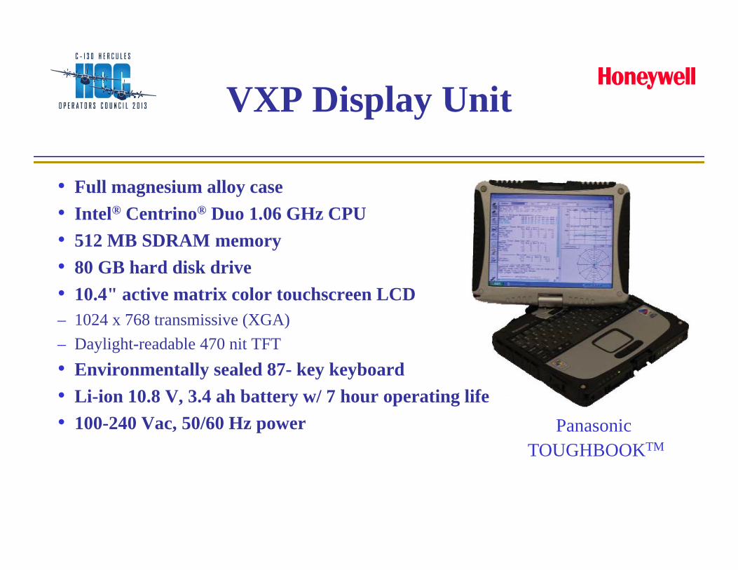
Panasonic TOUGHBOOKTM
VXP Display Unit
• Full magnesium alloy case• Intel® Centrino® Duo 1.06 GHz CPU• 512 MB SDRAM memory• 80 GB hard disk drive• 10.4" active matrix color touchscreen LCD– 1024 x 768 transmissive (XGA)– Daylight-readable 470 nit TFT• Environmentally sealed 87- key keyboard• Li-ion 10.8 V, 3.4 ah battery w/ 7 hour operating life• 100-240 Vac, 50/60 Hz power
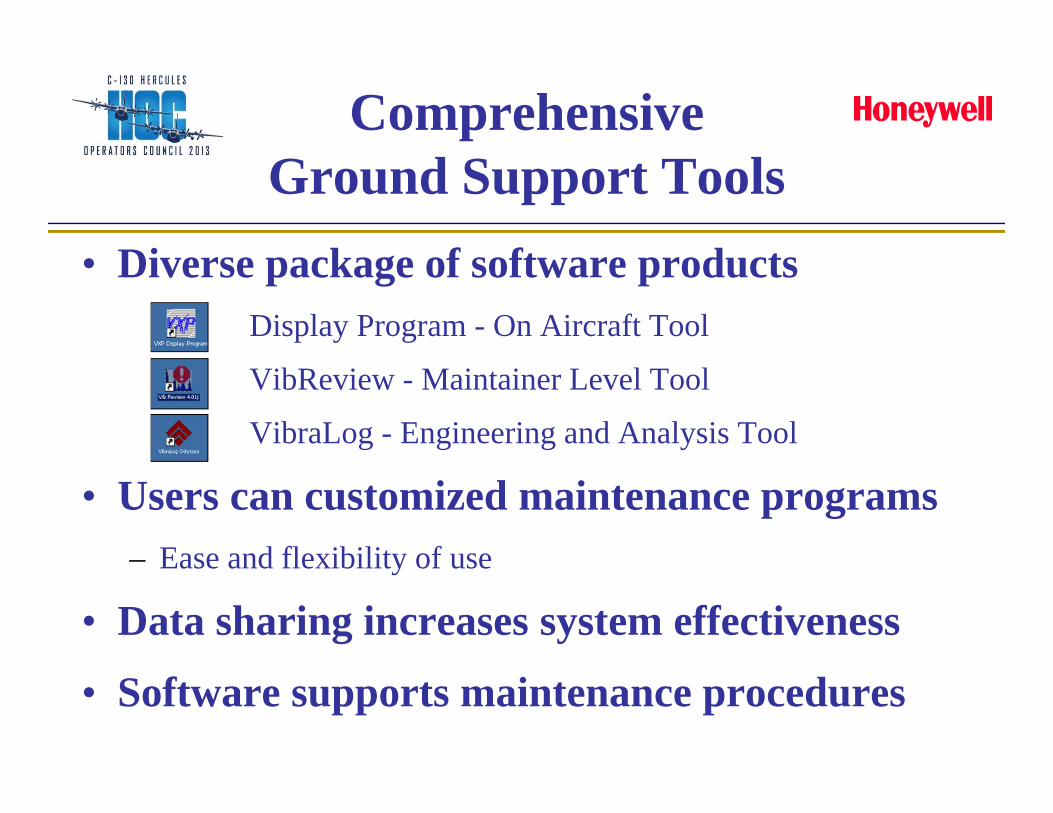
Comprehensive Ground Support Tools
• Diverse package of software productsDisplay Program - On Aircraft Tool
VibReview - Maintainer Level Tool
VibraLog - Engineering and Analysis Tool
• Users can customized maintenance programs– Ease and flexibility of use
• Data sharing increases system effectiveness
• Software supports maintenance procedures
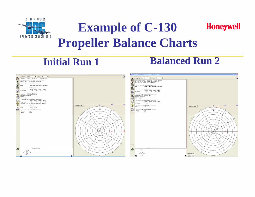
Example of C-130 Propeller Balance Charts
Initial Run 1 Balanced Run 2
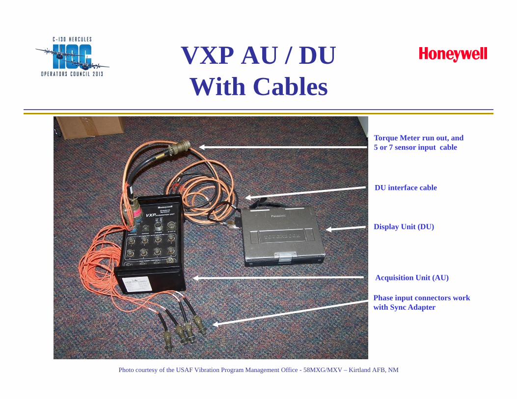
VXP AU / DU With Cables
Phase input connectors work with Sync Adapter
Torque Meter run out, and 5 or 7 sensor input cable
DU interface cable
Display Unit (DU)
Acquisition Unit (AU)
Photo courtesy of the USAF Vibration Program Management Office - 58MXG/MXV – Kirtland AFB, NM
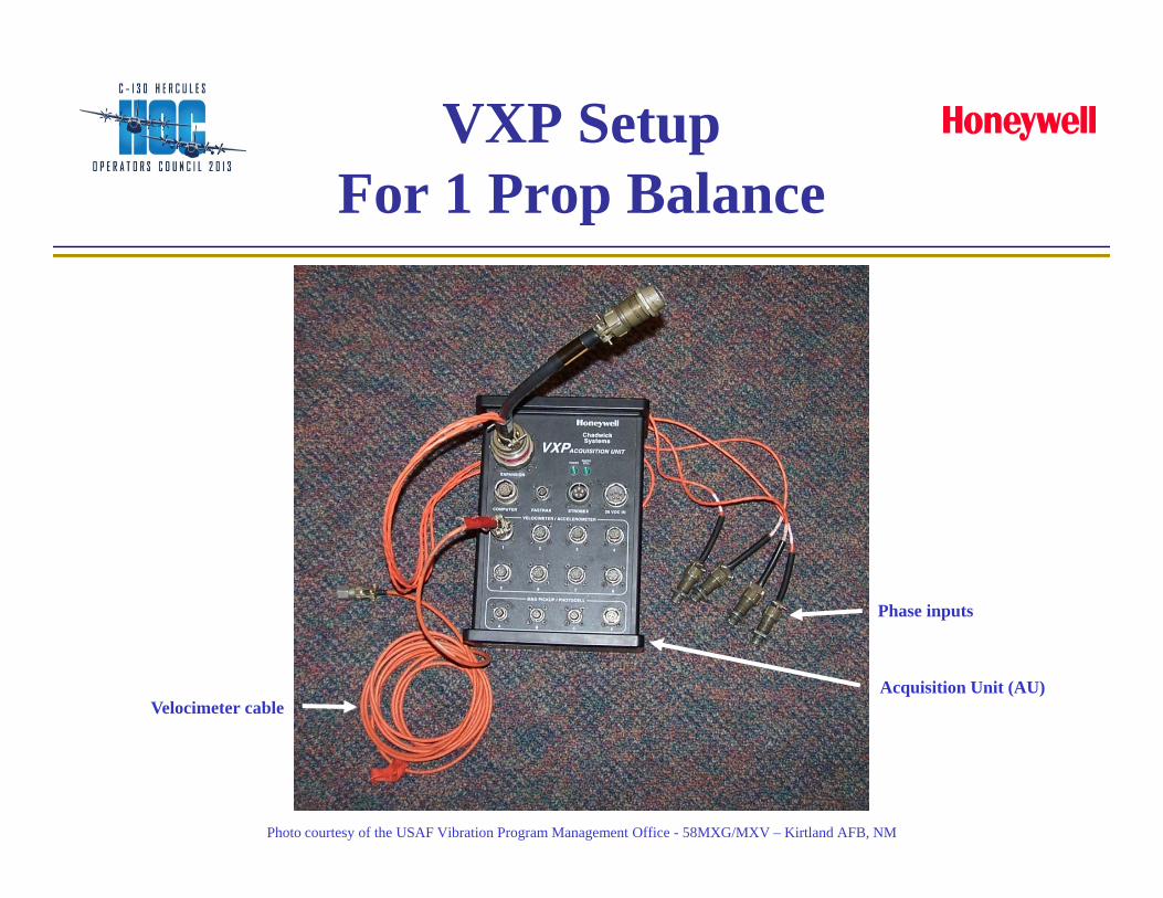
VXP SetupFor 1 Prop Balance
Velocimeter cable
Phase inputs
Acquisition Unit (AU)
Photo courtesy of the USAF Vibration Program Management Office - 58MXG/MXV – Kirtland AFB, NM

VXP Set Up ForTurbine Seal Break-in
Charge Amplifier
Accelerometer cable
Velocimeter cable
Phase inputs
Photo courtesy of the USAF Vibration Program Management Office - 58MXG/MXV – Kirtland AFB, NM
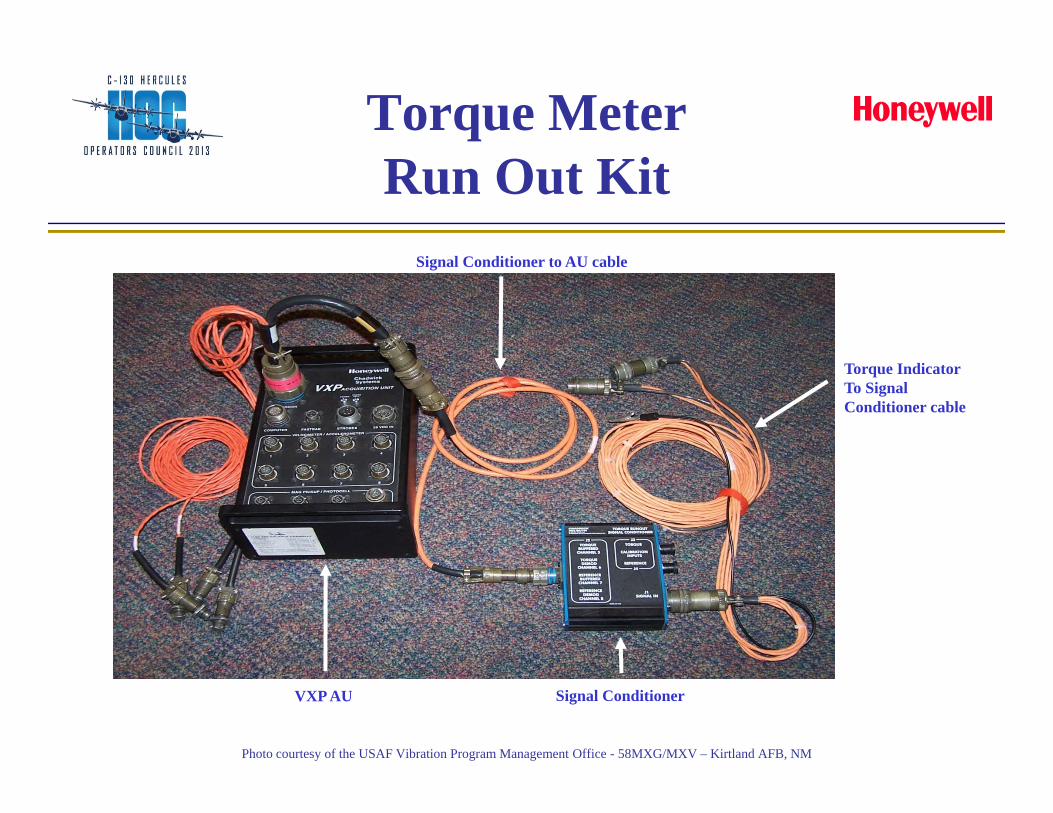
Torque Meter Run Out Kit
Signal Conditioner to AU cable
Torque IndicatorTo Signal Conditioner cable
Signal ConditionerVXP AU
Photo courtesy of the USAF Vibration Program Management Office - 58MXG/MXV – Kirtland AFB, NM
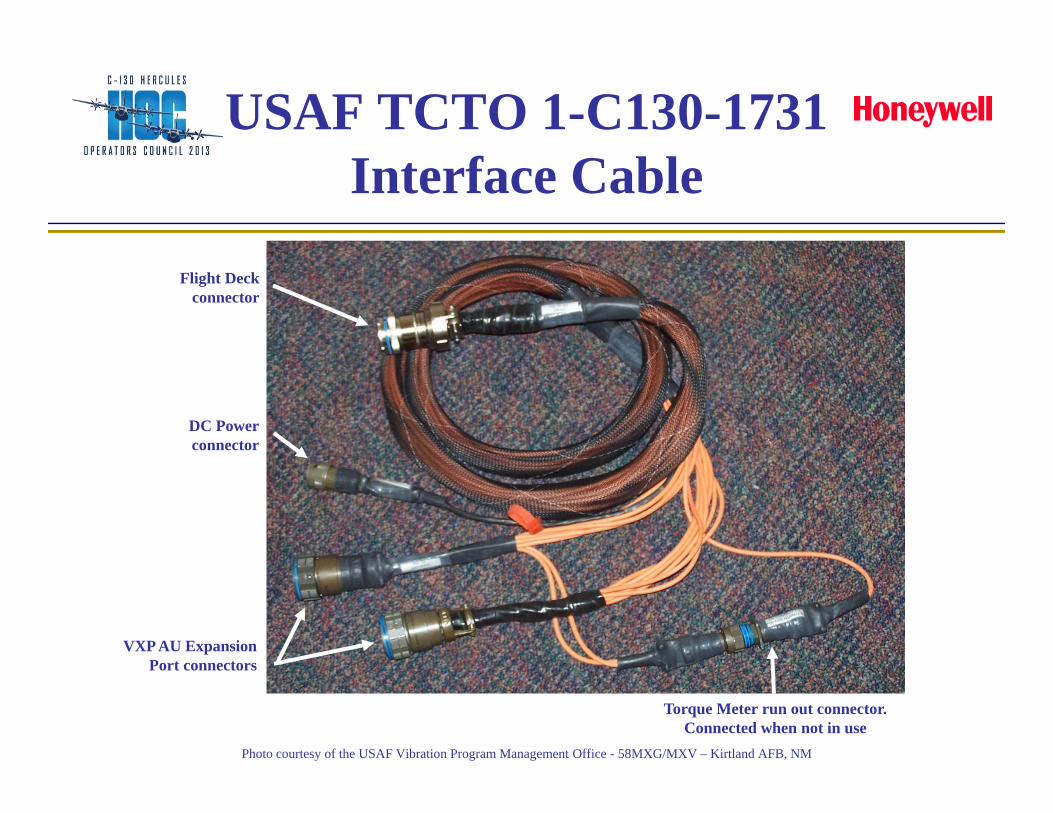
USAF TCTO 1-C130-1731Interface Cable
Flight Deck connector
DC Powerconnector
VXP AU ExpansionPort connectors
Torque Meter run out connector. Connected when not in use
Photo courtesy of the USAF Vibration Program Management Office - 58MXG/MXV – Kirtland AFB, NM
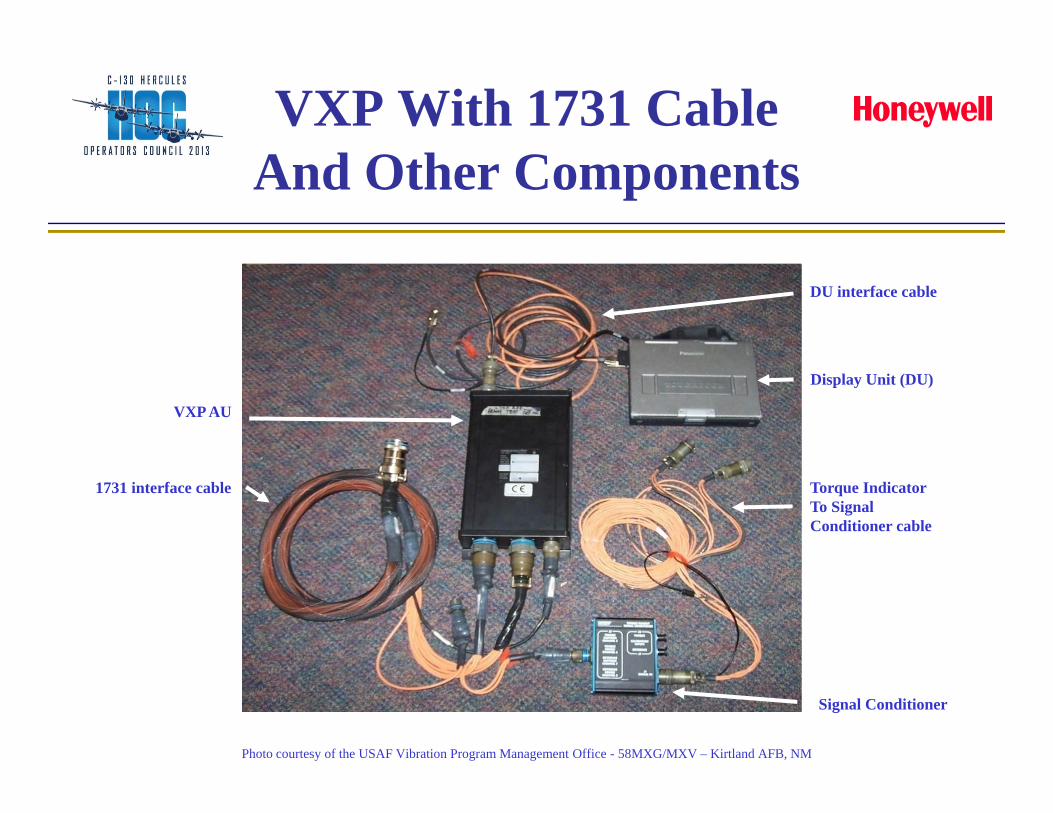
VXP With 1731 CableAnd Other Components
1731 interface cable
VXP AU
Display Unit (DU)
Signal Conditioner
Torque IndicatorTo Signal Conditioner cable
DU interface cable
Photo courtesy of the USAF Vibration Program Management Office - 58MXG/MXV – Kirtland AFB, NM
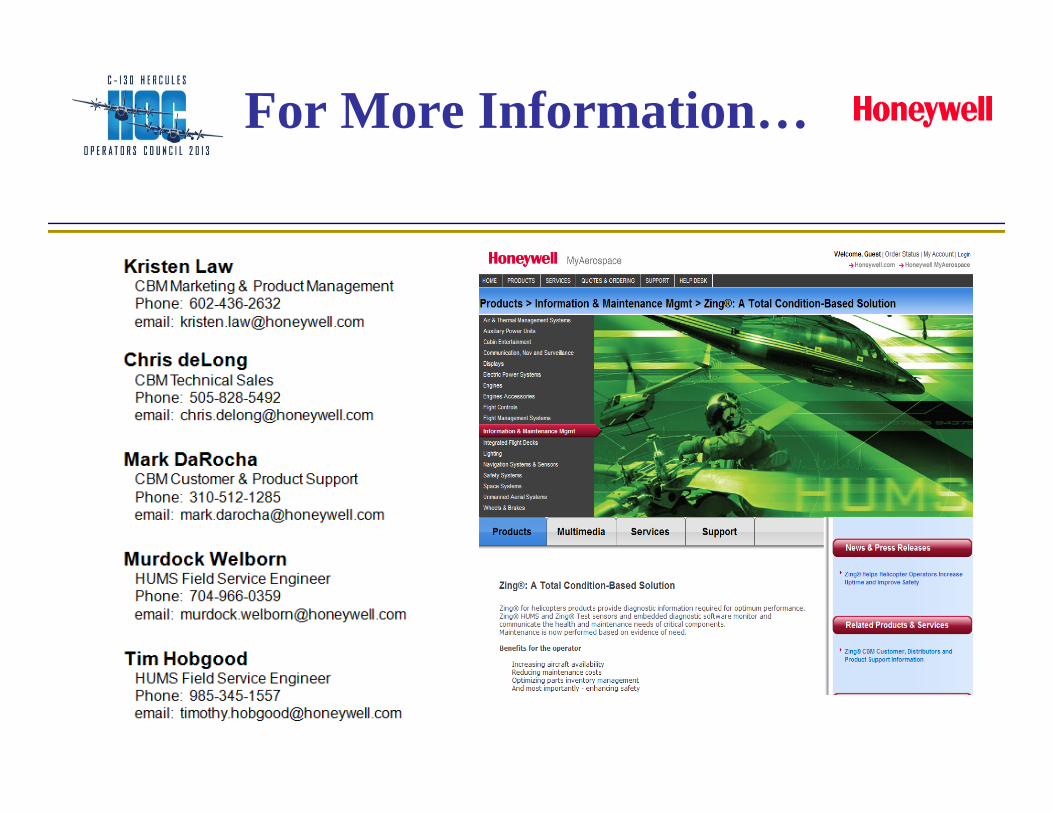
For More Information…

Visit Us For More Information
Booths: 12-15, 38-39