Embed Size (px)
Citation preview
SISTEMI EMBEDDED AA 2013/2014
System Interconnect Fabric
Federico Baron>

System Interconnect Fabric
• Interconnect and logic resources to manage whole connec>vity among all components in a Altera SoPC system
• Is automa>cally generated by Qsys/SoPC Builder – Components must comply with the standardized Avalon® interfaces, which are specialized for: • Reading and wri>ng registers and memory • Streaming high-‐speed data • Controlling off-‐chip devices
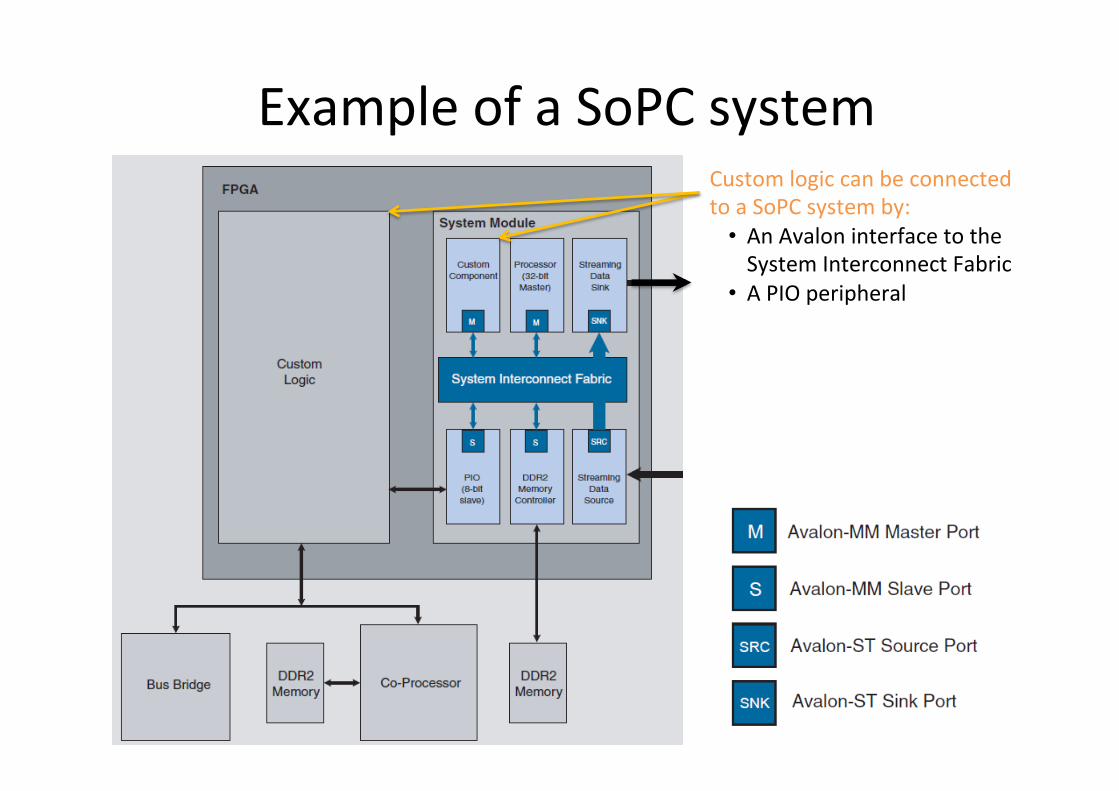
Example of a SoPC system Custom logic can be connected to a SoPC system by: • An Avalon interface to the System Interconnect Fabric
• A PIO peripheral
Avalon interfaces (1)
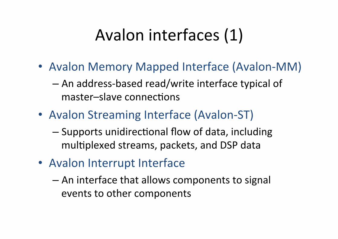
• Avalon Memory Mapped Interface (Avalon-‐MM) – An address-‐based read/write interface typical of master–slave connec>ons
• Avalon Streaming Interface (Avalon-‐ST) – Supports unidirec>onal flow of data, including mul>plexed streams, packets, and DSP data
• Avalon Interrupt Interface – An interface that allows components to signal events to other components
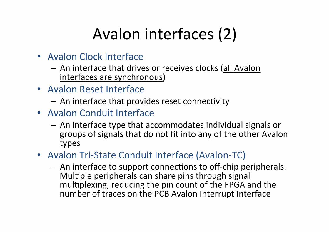
Avalon interfaces (2) • Avalon Clock Interface – An interface that drives or receives clocks (all Avalon interfaces are synchronous)
• Avalon Reset Interface – An interface that provides reset connec>vity
• Avalon Conduit Interface – An interface type that accommodates individual signals or groups of signals that do not fit into any of the other Avalon types
• Avalon Tri-‐State Conduit Interface (Avalon-‐TC) – An interface to support connec>ons to off-‐chip peripherals. Mul>ple peripherals can share pins through signal mul>plexing, reducing the pin count of the FPGA and the number of traces on the PCB Avalon Interrupt Interface
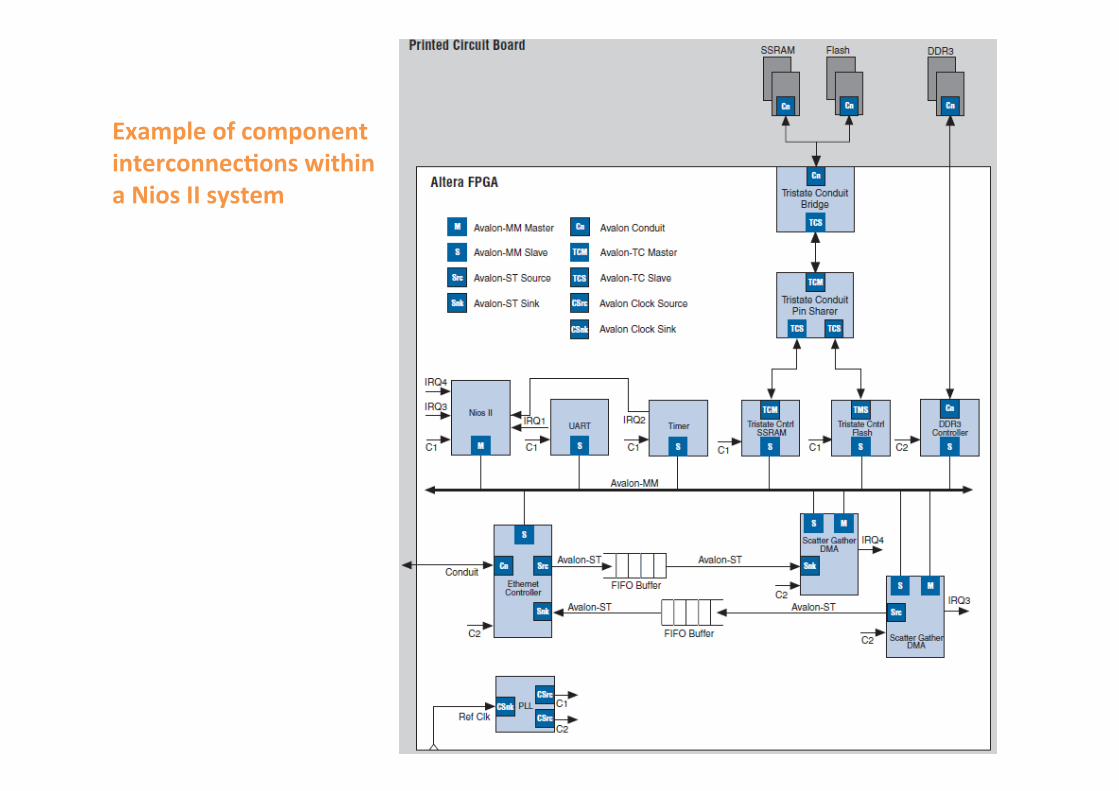
Example of component interconnec3ons within a Nios II system
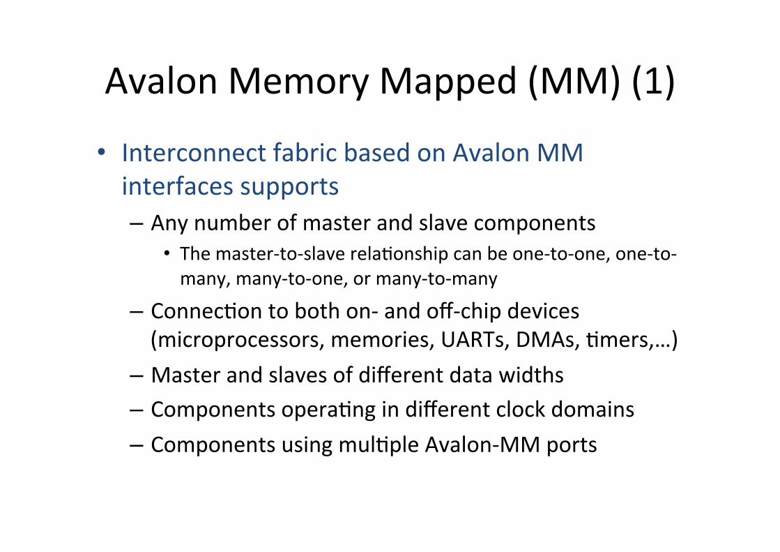
Avalon Memory Mapped (MM) (1)
• Interconnect fabric based on Avalon MM interfaces supports – Any number of master and slave components
• The master-‐to-‐slave rela>onship can be one-‐to-‐one, one-‐to-‐many, many-‐to-‐one, or many-‐to-‐many
– Connec>on to both on-‐ and off-‐chip devices (microprocessors, memories, UARTs, DMAs, >mers,…)
– Master and slaves of different data widths – Components opera>ng in different clock domains – Components using mul>ple Avalon-‐MM ports
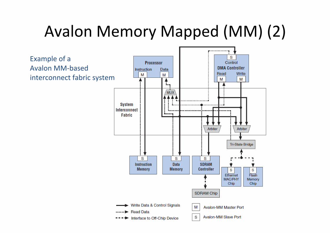
Avalon Memory Mapped (MM) (2) Example of a Avalon MM-‐based interconnect fabric system
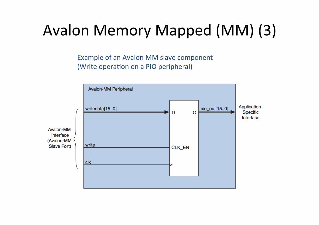
Avalon Memory Mapped (MM) (3) Example of an Avalon MM slave component (Write opera>on on a PIO peripheral)
Func>ons of Avalon MM fabric
• Address Decoding • Datapath Mul>plexing • Wait State Inser>on • Pipelined Read Transfers • Arbitra>on for Mul>master Systems • Burst Adapters

Address decoding (1) • Address decoding logic forwards appropriate addresses to each slave
• Address decoding logic simplifies component design in the following ways: – The system interconnect fabric selects a slave whenever it is being addressed by a master. Slave components do not need to decode the address to determine when they are selected
– Slave addresses are properly aligned to the slave interface
– Changing the system memory map does not involve manually edi>ng HDL
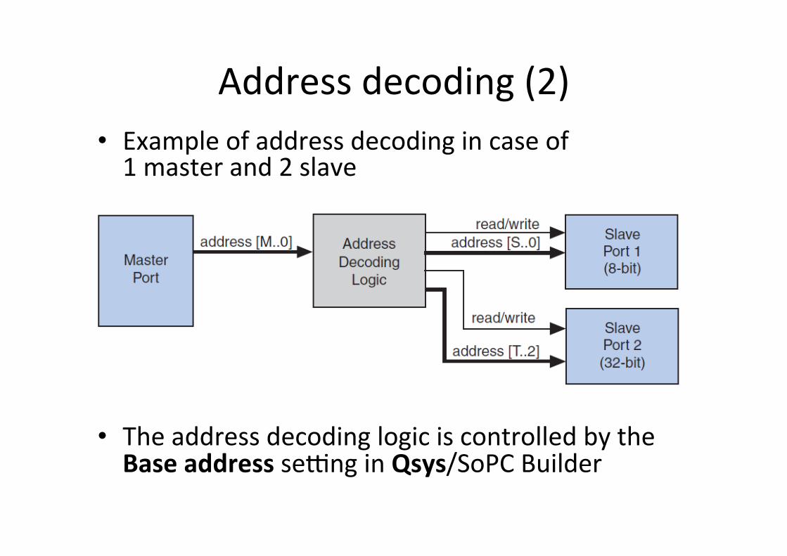
Address decoding (2) • Example of address decoding in case of 1 master and 2 slave
• The address decoding logic is controlled by the Base address se_ng in Qsys/SoPC Builder
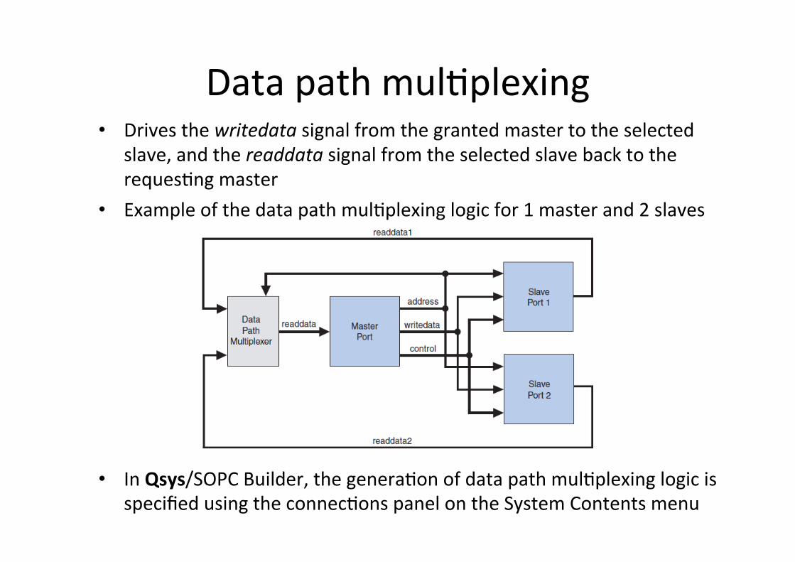
Data path mul>plexing • Drives the writedata signal from the granted master to the selected
slave, and the readdata signal from the selected slave back to the reques>ng master
• Example of the data path mul>plexing logic for 1 master and 2 slaves
• In Qsys/SOPC Builder, the genera>on of data path mul>plexing logic is specified using the connec>ons panel on the System Contents menu
Wait state inser>on
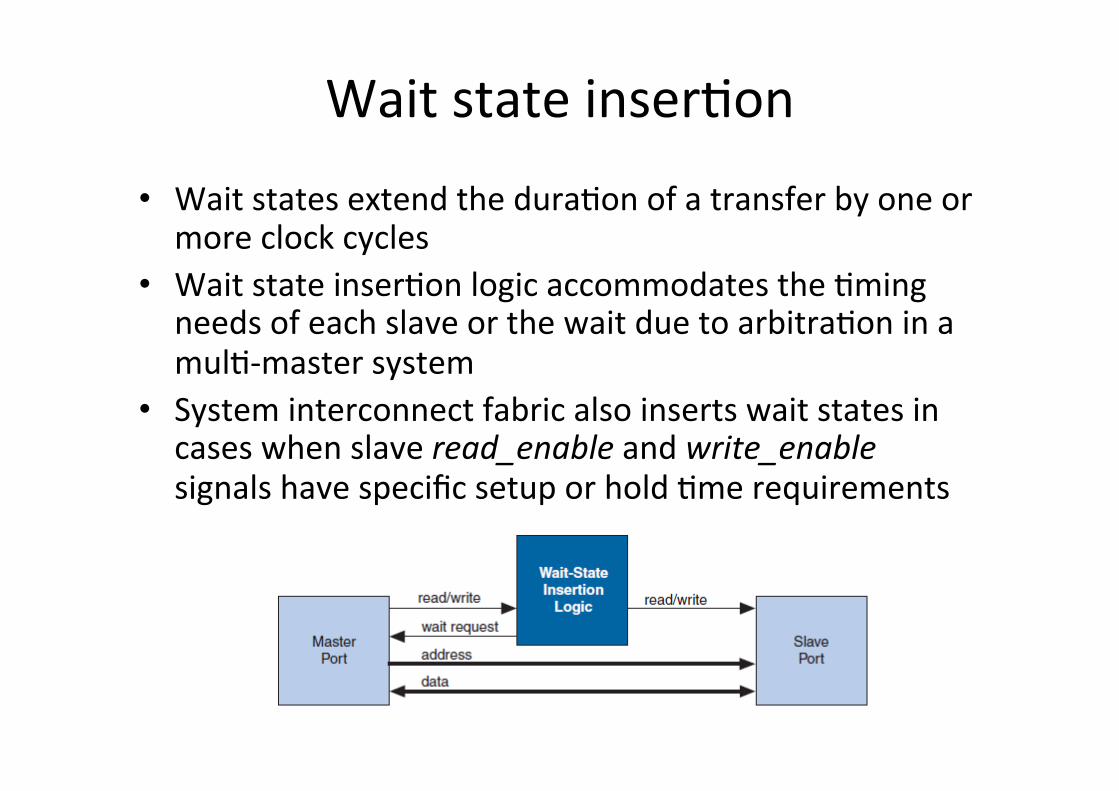
• Wait states extend the dura>on of a transfer by one or more clock cycles
• Wait state inser>on logic accommodates the >ming needs of each slave or the wait due to arbitra>on in a mul>-‐master system
• System interconnect fabric also inserts wait states in cases when slave read_enable and write_enable signals have specific setup or hold >me requirements

Pipelined read transfer • The Avalon-‐MM interface supports pipelined read
transfers, allowing a pipelined master to start mul>ple read transfers in succession without wai>ng for the prior transfers to complete
• Pipelined transfers allow master-‐slave pairs to achieve higher throughput, even though the slave requires one or more cycles of latency to return data for each transfer
• Qsys/SOPC Builder generates logic to handle pipeline latency based on the proper>es of the master and slaves in the system. When configuring a system in Qsys/SOPC Builder, there are no se_ngs that directly control the pipeline management logic in the system interconnect fabric
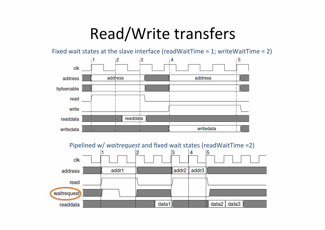
Read/Write transfers
Pipelined w/ waitrequest and fixed wait states (readWaitTime =2)
Fixed wait states at the slave interface (readWaitTime = 1; writeWaitTime = 2)
Interrupts (1)
• In systems where components have interrupt request (IRQ) sender interfaces, the system interconnect fabric includes interrupt controller logic
• A separate interrupt (controller) router is generated for each interrupt receiver
• The interrupt controller aggregates IRQ signals from all interrupt senders, and maps them to user-‐specified values on the receiver inputs
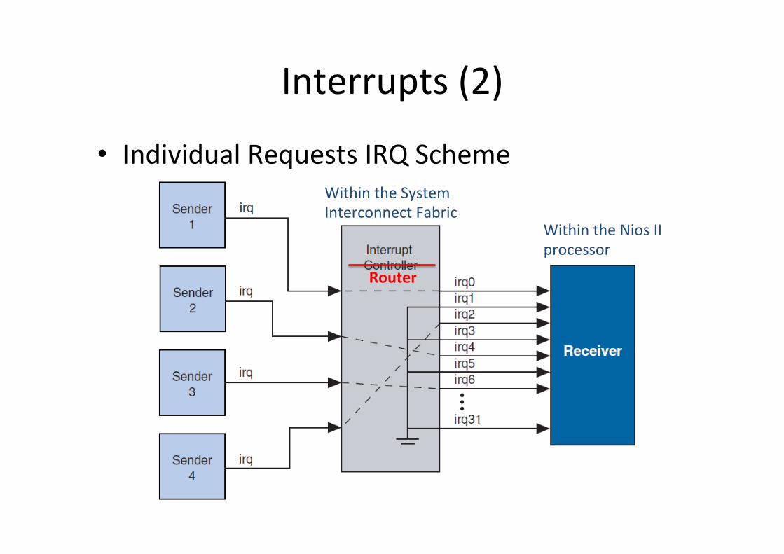
Interrupts (2)
• Individual Requests IRQ Scheme
Router
Within the System Interconnect Fabric
Within the Nios II processor
Reset distribu>on • SOPC Builder generates the logic to drives the reset pulse
to all components • The system interconnect fabric distributes the reset signal
condi>oned for each clock domain – The dura>on of the reset signal is at least one clock period
• The system interconnect fabric asserts the system-‐wide reset in the following condi>ons: – The global reset input to the SOPC Builder system is asserted – Any component asserts its resetrequest signal (eg. Watchdog)
• The global reset and reset requests are ORed together. This signal is then synchronized to each clock domain associated to an Avalon-‐MM port, which causes the asynchronous resets to be de-‐asserted synchronously
Component development flow • Specifica>on and defini>on – Define the func>onality of the component – Determine component interfaces, such as Avalon-‐MM, Avalon-‐ST, interrupt, or other interfaces
– Determine the component clocking requirements; what interfaces are synchronous to what clock inputs
– If you want a microprocessor to control the component, determine the interface to soeware, such as the register map
• Implement the component in VHDL or Verilog HDL • Import the component into Qsys/SoPC Builder – Use the component editor to create a _hw.tcl file that describes the component
– Instan>ate the component into a Qsys/SOPC Builder system
References
• Altera, “Avalon Interface Specifica>ons,” mnl_avalon_spec.pdf
• Altera, “SoPC Builder User Guide,” ug_sopc_builder.pdf – 2. System Interconnect Fabric for Memory-‐Mapped Interfaces