Embed Size (px)
Citation preview

101 Innovation DriveSan Jose, CA 95134www.altera.com
UG-N2CSTNST-2.0
User Guide
Nios II Custom Instruction
Subscribe
Nios II Custom Instruction User Guide

Nios II Custom Instruction User Guide January 2011 Altera Corporation
© 2011 Altera Corporation. All rights reserved. ALTERA, ARRIA, CYCLONE, HARDCOPY, MAX, MEGACORE, NIOS, QUARTUS and STRATIX are Reg. U.S. Pat.& Tm. Off. and/or trademarks of Altera Corporation in the U.S. and other countries. All other trademarks and service marks are the property of their respectiveholders as described at www.altera.com/common/legal.html. Altera warrants performance of its semiconductor products to current specifications in accordancewith Altera’s standard warranty, but reserves the right to make changes to any products and services at any time without notice. Altera assumes no responsibility orliability arising out of the application or use of any information, product, or service described herein except as expressly agreed to in writing by Altera. Alteracustomers are advised to obtain the latest version of device specifications before relying on any published information and before placing orders for products orservices.

January 2011 Altera Corporation
Contents
Chapter 1. Nios II Custom Instruction OverviewCustom Instruction Overview . . . . . . . . . . . . . . . . . . . . . . . . . . . . . . . . . . . . . . . . . . . . . . . . . . . . . . . . . . . . . 1–2
Implementing Custom Instruction Hardware . . . . . . . . . . . . . . . . . . . . . . . . . . . . . . . . . . . . . . . . . . . . . 1–2Implementing Custom Instruction Software . . . . . . . . . . . . . . . . . . . . . . . . . . . . . . . . . . . . . . . . . . . . . . 1–3
Custom Instruction Types . . . . . . . . . . . . . . . . . . . . . . . . . . . . . . . . . . . . . . . . . . . . . . . . . . . . . . . . . . . . . . . . 1–3Combinational Custom Instructions . . . . . . . . . . . . . . . . . . . . . . . . . . . . . . . . . . . . . . . . . . . . . . . . . . . . . 1–4Multicycle Custom Instructions . . . . . . . . . . . . . . . . . . . . . . . . . . . . . . . . . . . . . . . . . . . . . . . . . . . . . . . . . 1–5Extended Custom Instructions . . . . . . . . . . . . . . . . . . . . . . . . . . . . . . . . . . . . . . . . . . . . . . . . . . . . . . . . . . 1–7Internal Register File Custom Instructions . . . . . . . . . . . . . . . . . . . . . . . . . . . . . . . . . . . . . . . . . . . . . . . . 1–9External Interface Custom Instructions . . . . . . . . . . . . . . . . . . . . . . . . . . . . . . . . . . . . . . . . . . . . . . . . . . 1–10
Chapter 2. Software InterfaceCustom Instruction Examples . . . . . . . . . . . . . . . . . . . . . . . . . . . . . . . . . . . . . . . . . . . . . . . . . . . . . . . . . . . . . 2–1Built-in Functions and User-defined Macros . . . . . . . . . . . . . . . . . . . . . . . . . . . . . . . . . . . . . . . . . . . . . . . . 2–2Custom Instruction Assembly Software Interface . . . . . . . . . . . . . . . . . . . . . . . . . . . . . . . . . . . . . . . . . . . . 2–3
Chapter 3. Implementing a Nios II Custom Instruction in SOPC BuilderDesign Example: Cyclic Redundancy Check . . . . . . . . . . . . . . . . . . . . . . . . . . . . . . . . . . . . . . . . . . . . . . . . 3–1Implementing Custom Instruction Hardware in SOPC Builder . . . . . . . . . . . . . . . . . . . . . . . . . . . . . . . . 3–1
Setting up the Design Environment for the Design Example . . . . . . . . . . . . . . . . . . . . . . . . . . . . . . . . 3–2Opening the Component Editor . . . . . . . . . . . . . . . . . . . . . . . . . . . . . . . . . . . . . . . . . . . . . . . . . . . . . . . . . 3–2Adding the HDL Files . . . . . . . . . . . . . . . . . . . . . . . . . . . . . . . . . . . . . . . . . . . . . . . . . . . . . . . . . . . . . . . . . 3–2Configuring the Custom Instruction Signal Type . . . . . . . . . . . . . . . . . . . . . . . . . . . . . . . . . . . . . . . . . . 3–3Setting Up the Custom Instruction Interfaces . . . . . . . . . . . . . . . . . . . . . . . . . . . . . . . . . . . . . . . . . . . . . 3–3Setting the Details . . . . . . . . . . . . . . . . . . . . . . . . . . . . . . . . . . . . . . . . . . . . . . . . . . . . . . . . . . . . . . . . . . . . . 3–4Saving and Adding the Custom Instruction . . . . . . . . . . . . . . . . . . . . . . . . . . . . . . . . . . . . . . . . . . . . . . . 3–5Generating the System and Compiling in the Quartus II Software . . . . . . . . . . . . . . . . . . . . . . . . . . . 3–5
Accessing the Custom Instruction from Software . . . . . . . . . . . . . . . . . . . . . . . . . . . . . . . . . . . . . . . . . . . . 3–6Using the User-defined Custom Instruction Macro . . . . . . . . . . . . . . . . . . . . . . . . . . . . . . . . . . . . . . . . . . . 3–8
Chapter 4. Implementing a Nios II Custom Instruction in QsysDesign Example: Cyclic Redundancy Check . . . . . . . . . . . . . . . . . . . . . . . . . . . . . . . . . . . . . . . . . . . . . . . . 4–1Implementing Custom Instruction Hardware in Qsys . . . . . . . . . . . . . . . . . . . . . . . . . . . . . . . . . . . . . . . . 4–1
Setting up the Design Environment for the Design Example . . . . . . . . . . . . . . . . . . . . . . . . . . . . . . . . 4–2Opening the Component Editor . . . . . . . . . . . . . . . . . . . . . . . . . . . . . . . . . . . . . . . . . . . . . . . . . . . . . . . . . 4–2Adding the HDL Files . . . . . . . . . . . . . . . . . . . . . . . . . . . . . . . . . . . . . . . . . . . . . . . . . . . . . . . . . . . . . . . . . 4–2Configuring the Custom Instruction Signal Type . . . . . . . . . . . . . . . . . . . . . . . . . . . . . . . . . . . . . . . . . . 4–3Setting Up the Custom Instruction Interfaces . . . . . . . . . . . . . . . . . . . . . . . . . . . . . . . . . . . . . . . . . . . . . 4–3Setting the Details . . . . . . . . . . . . . . . . . . . . . . . . . . . . . . . . . . . . . . . . . . . . . . . . . . . . . . . . . . . . . . . . . . . . . 4–4Saving and Adding the Custom Instruction . . . . . . . . . . . . . . . . . . . . . . . . . . . . . . . . . . . . . . . . . . . . . . . 4–5Generating the System and Compiling in the Quartus II Software . . . . . . . . . . . . . . . . . . . . . . . . . . . 4–5
Accessing the Custom Instruction from Software . . . . . . . . . . . . . . . . . . . . . . . . . . . . . . . . . . . . . . . . . . . . 4–5Using the User-defined Custom Instruction Macro . . . . . . . . . . . . . . . . . . . . . . . . . . . . . . . . . . . . . . . . . . . 4–8
Appendix A. Custom Instruction TemplatesVHDL Custom Instruction Template . . . . . . . . . . . . . . . . . . . . . . . . . . . . . . . . . . . . . . . . . . . . . . . . . . . . . . A–2Verilog HDL Custom Instruction Template Example . . . . . . . . . . . . . . . . . . . . . . . . . . . . . . . . . . . . . . . . A–3
Nios II Custom Instruction User Guide
iv Contents
Appendix B. Custom Instruction Built-in FunctionsBuilt-in Functions that Return a Void Value . . . . . . . . . . . . . . . . . . . . . . . . . . . . . . . . . . . . . . . . . . . . . . . . B–1Built-in Functions that Return a Value of Type Int . . . . . . . . . . . . . . . . . . . . . . . . . . . . . . . . . . . . . . . . . . B–1Built-in Functions that Return a Value of Type Float . . . . . . . . . . . . . . . . . . . . . . . . . . . . . . . . . . . . . . . . B–2Built-in Functions that Return a Pointer Value . . . . . . . . . . . . . . . . . . . . . . . . . . . . . . . . . . . . . . . . . . . . . . B–2
Appendix C. Floating Point Custom Instructions
Additional InformationDocument Revision History . . . . . . . . . . . . . . . . . . . . . . . . . . . . . . . . . . . . . . . . . . . . . . . . . . . . . . . . . . . Info–1How to Contact Altera . . . . . . . . . . . . . . . . . . . . . . . . . . . . . . . . . . . . . . . . . . . . . . . . . . . . . . . . . . . . . . . . Info–1Typographic Conventions . . . . . . . . . . . . . . . . . . . . . . . . . . . . . . . . . . . . . . . . . . . . . . . . . . . . . . . . . . . . . Info–2
Nios II Custom Instruction User Guide January 2011 Altera Corporation
January 2011 Altera Corporation
1. Nios II Custom Instruction Overview
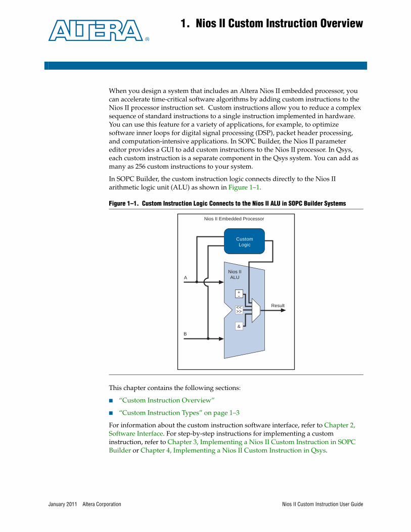
When you design a system that includes an Altera Nios II embedded processor, you can accelerate time-critical software algorithms by adding custom instructions to the Nios II processor instruction set. Custom instructions allow you to reduce a complex sequence of standard instructions to a single instruction implemented in hardware. You can use this feature for a variety of applications, for example, to optimize software inner loops for digital signal processing (DSP), packet header processing, and computation-intensive applications. In SOPC Builder, the Nios II parameter editor provides a GUI to add custom instructions to the Nios II processor. In Qsys, each custom instruction is a separate component in the Qsys system. You can add as many as 256 custom instructions to your system.
In SOPC Builder, the custom instruction logic connects directly to the Nios II arithmetic logic unit (ALU) as shown in Figure 1–1.
This chapter contains the following sections:
■ “Custom Instruction Overview”
■ “Custom Instruction Types” on page 1–3
For information about the custom instruction software interface, refer to Chapter 2, Software Interface. For step-by-step instructions for implementing a custom instruction, refer to Chapter 3, Implementing a Nios II Custom Instruction in SOPC Builder or Chapter 4, Implementing a Nios II Custom Instruction in Qsys.
Figure 1–1. Custom Instruction Logic Connects to the Nios II ALU in SOPC Builder Systems
Nios II Embedded Processor
+-
&
<<>>
Result
ANios IIALU
B
Custom Logic
Nios II Custom Instruction User Guide

1–2 Chapter 1: Nios II Custom Instruction OverviewCustom Instruction Overview
Custom Instruction OverviewNios II custom instructions are custom logic blocks adjacent to the ALU in the processor’s datapath. Custom instructions give you the ability to tailor the Nios II processor core to meet the needs of a particular application. You can accelerate time critical software algorithms by converting them to custom hardware logic blocks. Because it is easy to alter the design of the FPGA-based Nios II processor, custom instructions provide an easy way to experiment with hardware-software tradeoffs at any point in the design process.
Implementing Custom Instruction HardwareFigure 1–2 is a hardware block diagram of a Nios II custom instruction.
A Nios II custom instruction logic receives input on its dataa port, or on its dataa and datab ports, and drives out the result on its result port. The custom instruction logic provides a result based on the inputs provided by the Nios II processor.
The Nios II processor supports different types of custom instructions. Figure 1–2 lists the additional ports that accommodate different custom instruction types. Only the ports used for the specific custom instruction implementation are required.
Figure 1–2 also shows a conduit interface to external logic. The interface to external logic allows you to include a custom interface to system resources outside of the Nios II processor datapath.
Figure 1–2. Hardware Block Diagram of a Nios II Custom Instruction
Combinatorial
Conduit interface to externalmemory, FIFO, or other logic
Multi-cycle
result
Extended
Internal Register File
[31..0]
done
dataa[31..0]
datab[31..0]
clk
clk_en
reset
start
n[7..0]
a[4..0] readra
b[4..0] readrb
c[4..0] writerc
Combinational
Custom Logic
Nios II Custom Instruction User Guide January 2011 Altera Corporation
Chapter 1: Nios II Custom Instruction Overview 1–3Custom Instruction Types
Implementing Custom Instruction SoftwareThe Nios II custom instruction software interface is simple and abstracts the details of the custom instruction from the software developer. For each custom instruction, the Nios II Embedded Design Suite (EDS) generates a macro in the system header file, system.h. You can use the macro directly in your C or C++ application code, and you do not need to program assembly code to access custom instructions. Software can also invoke custom instructions in Nios II processor assembly language.
For more information about the custom instruction software interface, refer to Chapter 2, Software Interface.
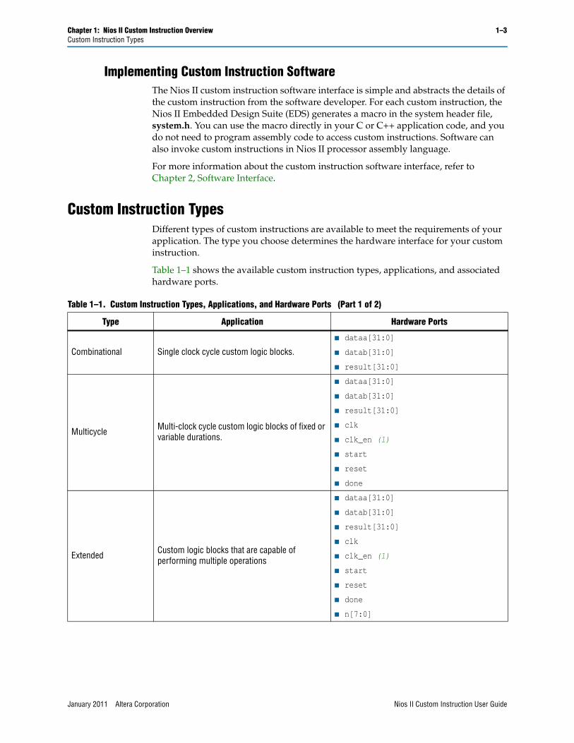
Custom Instruction TypesDifferent types of custom instructions are available to meet the requirements of your application. The type you choose determines the hardware interface for your custom instruction.
Table 1–1 shows the available custom instruction types, applications, and associated hardware ports.
Table 1–1. Custom Instruction Types, Applications, and Hardware Ports (Part 1 of 2)
Type Application Hardware Ports
Combinational Single clock cycle custom logic blocks.
■ dataa[31:0]
■ datab[31:0]
■ result[31:0]
Multicycle Multi-clock cycle custom logic blocks of fixed or variable durations.
■ dataa[31:0]
■ datab[31:0]
■ result[31:0]
■ clk
■ clk_en (1)
■ start
■ reset
■ done
Extended Custom logic blocks that are capable of performing multiple operations
■ dataa[31:0]
■ datab[31:0]
■ result[31:0]
■ clk
■ clk_en (1)
■ start
■ reset
■ done
■ n[7:0]
January 2011 Altera Corporation Nios II Custom Instruction User Guide
1–4 Chapter 1: Nios II Custom Instruction OverviewCustom Instruction Types
The following sections discuss the basic functionality and hardware interface of each of the custom instruction types listed in Table 1–1.
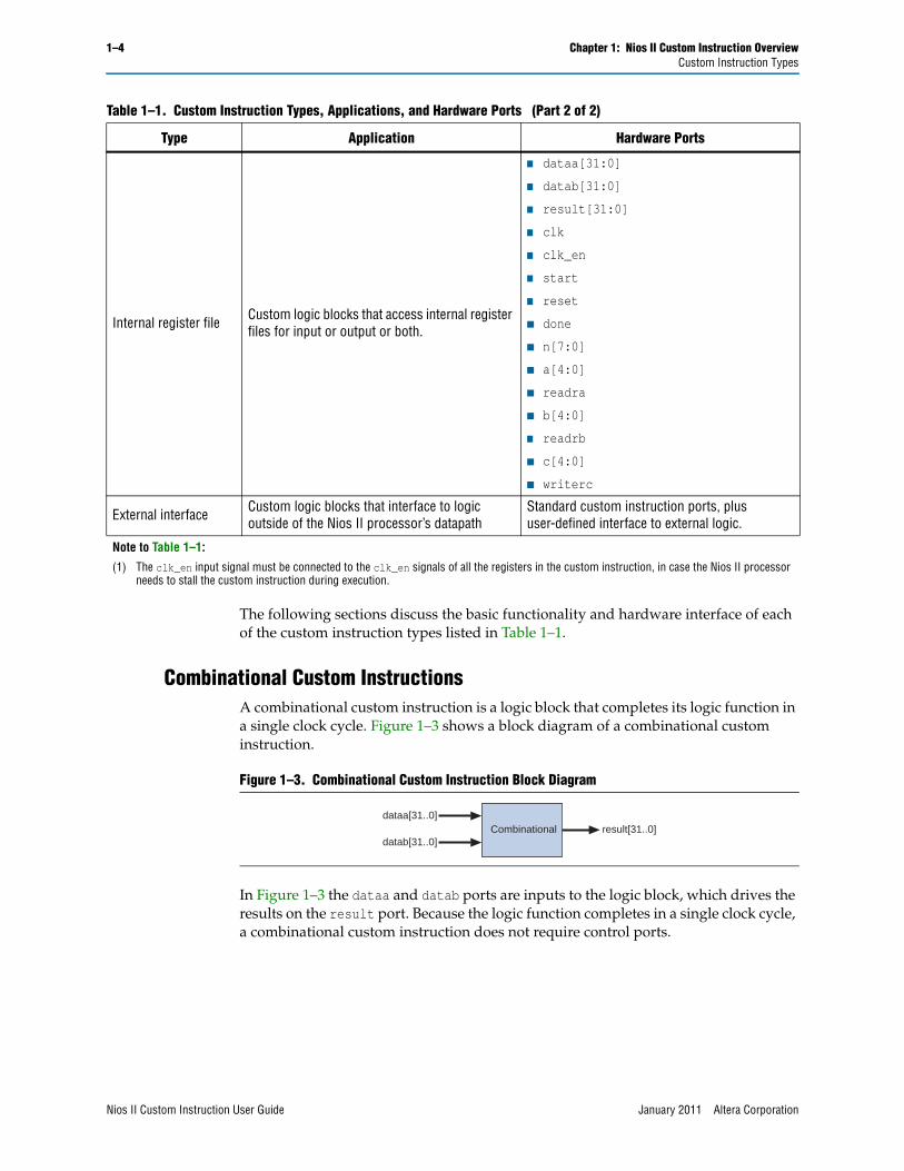
Combinational Custom InstructionsA combinational custom instruction is a logic block that completes its logic function in a single clock cycle. Figure 1–3 shows a block diagram of a combinational custom instruction.
In Figure 1–3 the dataa and datab ports are inputs to the logic block, which drives the results on the result port. Because the logic function completes in a single clock cycle, a combinational custom instruction does not require control ports.
Internal register file Custom logic blocks that access internal register files for input or output or both.
■ dataa[31:0]
■ datab[31:0]
■ result[31:0]
■ clk
■ clk_en
■ start
■ reset
■ done
■ n[7:0]
■ a[4:0]
■ readra
■ b[4:0]
■ readrb
■ c[4:0]
■ writerc
External interface Custom logic blocks that interface to logic outside of the Nios II processor’s datapath
Standard custom instruction ports, plus user-defined interface to external logic.
Note to Table 1–1:
(1) The clk_en input signal must be connected to the clk_en signals of all the registers in the custom instruction, in case the Nios II processor needs to stall the custom instruction during execution.
Table 1–1. Custom Instruction Types, Applications, and Hardware Ports (Part 2 of 2)
Type Application Hardware Ports
Figure 1–3. Combinational Custom Instruction Block Diagram
dataa[31..0]
datab[31..0]Combinational result[31..0]
Nios II Custom Instruction User Guide January 2011 Altera Corporation
Chapter 1: Nios II Custom Instruction Overview 1–5Custom Instruction Types
Table 1–2 describes the combination custom instruction ports.
The only required port for combinational custom instructions is the result port. The dataa and datab ports are optional. Include them only if the custom instruction functionality requires input operands. If the custom instruction requires only a single input port, use dataa.
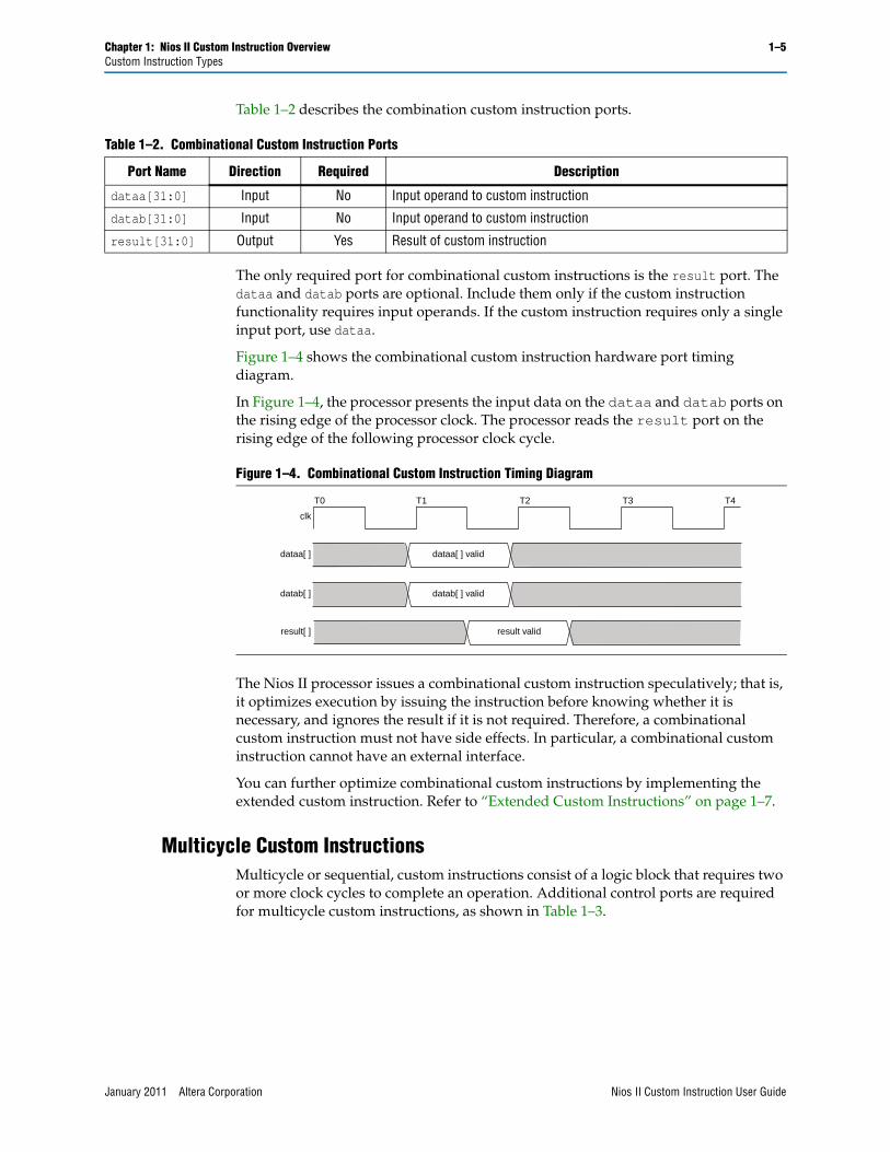
Figure 1–4 shows the combinational custom instruction hardware port timing diagram.
In Figure 1–4, the processor presents the input data on the dataa and datab ports on the rising edge of the processor clock. The processor reads the result port on the rising edge of the following processor clock cycle.
The Nios II processor issues a combinational custom instruction speculatively; that is, it optimizes execution by issuing the instruction before knowing whether it is necessary, and ignores the result if it is not required. Therefore, a combinational custom instruction must not have side effects. In particular, a combinational custom instruction cannot have an external interface.
You can further optimize combinational custom instructions by implementing the extended custom instruction. Refer to “Extended Custom Instructions” on page 1–7.
Multicycle Custom InstructionsMulticycle or sequential, custom instructions consist of a logic block that requires two or more clock cycles to complete an operation. Additional control ports are required for multicycle custom instructions, as shown in Table 1–3.
Table 1–2. Combinational Custom Instruction Ports
Port Name Direction Required Description
dataa[31:0] Input No Input operand to custom instruction
datab[31:0] Input No Input operand to custom instruction
result[31:0] Output Yes Result of custom instruction
Figure 1–4. Combinational Custom Instruction Timing Diagram
clk
T0 T1 T3T2 T4
dataa[ ]
datab[ ]
result[ ]
dataa[ ] valid
datab[ ] valid
result valid
January 2011 Altera Corporation Nios II Custom Instruction User Guide

1–6 Chapter 1: Nios II Custom Instruction OverviewCustom Instruction Types
Figure 1–5 shows the multicycle custom instruction block diagram.
Multicycle custom instructions complete in either a fixed or variable number of clock cycles. For a custom instruction that completes in a fixed number of clock cycles, you specify the required number of clock cycles at system generation. For a custom instruction that requires a variable number of clock cycles, you instantiate the start and done ports. These ports participate in a handshaking scheme to determine when the custom instruction execution is complete.
Table 1–3 describes the multicycle custom instruction ports.
As indicated in Table 1–3, the clk, clk_en, and reset ports are required for multicycle custom instructions. However, the start, done, dataa, datab, and result ports are optional. Implement them only if the custom instruction functionality requires them.
Figure 1–5. Multicycle Custom Instruction Block Diagram
dataa[31..0] datab[31..0]
clk clk_en
reset start
Multi-cycledone
result[31..0]
Table 1–3. Multicycle Custom Instruction Ports
Port Name Direction Required Description
clk Input Yes System clock
clk_en Input Yes Clock enable
reset Input Yes Synchronous reset
start Input No Commands custom instruction logic to start execution
done Output No Custom instruction logic indicates to the processor that execution is complete
dataa[31:0] Input No Input operand to custom instruction
datab[31:0] Input No Input operand to custom instruction
result[31:0] Output No Result of custom instruction
Nios II Custom Instruction User Guide January 2011 Altera Corporation
Chapter 1: Nios II Custom Instruction Overview 1–7Custom Instruction Types
Figure 1–6 shows the multicycle custom instruction hardware port timing diagram.
The processor asserts the active high start port on the first clock cycle of the custom instruction execution. At this time, the dataa and datab ports have valid values and remain valid throughout the duration of the custom instruction execution. The start signal is asserted for a single clock cycle.
For a fixed length multicycle custom instruction, after the instruction starts, the processor waits the specified number of clock cycles, and then reads the value on the result signal. For an n-cycle operation, the custom logic block must present valid data on the nth rising edge after the custom instruction begins execution.
For a variable length multicycle custom instruction, the processor waits until the active high done signal is asserted. The processor reads the result port on the same clock edge on which done is asserted. The custom logic block must present data on the result port on the same clock cycle on which it asserts the done signal.
The Nios II system clock feeds the custom logic block’s clk port, and the Nios II system’s master reset feeds the active high reset port. The reset port is asserted only when the whole Nios II system is reset.
The custom logic block must treat the active high clk_en port as a conventional clock qualifier signal, ignoring clk while clk_en is deasserted.
You can further optimize multicycle custom instructions by implementing the extended internal register file, or by creating external interface custom instructions. Refer to “Extended Custom Instructions”, “Internal Register File Custom Instructions” on page 1–9, or “External Interface Custom Instructions” on page 1–10.
Extended Custom InstructionsExtended custom instruction allows a single custom logic block to implement several different operations. Extended custom instructions use an index to specify which operation the logic block performs. The index can be as many as eight bits wide, allowing a single custom logic block to implement as many as 256 different operations.
Figure 1–6. Multicycle Custom Instruction Timing Diagram
clk
dataa[]
datab[]
result[]
valid
valid
T0 T1 T3T2 T4 T5 T6
valid
done
clk_en
start
reset
January 2011 Altera Corporation Nios II Custom Instruction User Guide
1–8 Chapter 1: Nios II Custom Instruction OverviewCustom Instruction Types
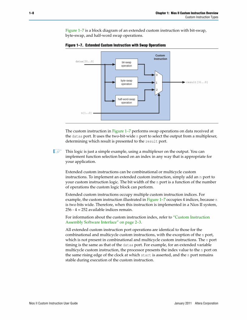
Figure 1–7 is a block diagram of an extended custom instruction with bit-swap, byte-swap, and half-word swap operations.
The custom instruction in Figure 1–7 performs swap operations on data received at the dataa port. It uses the two-bit-wide n port to select the output from a multiplexer, determining which result is presented to the result port.
1 This logic is just a simple example, using a multiplexer on the output. You can implement function selection based on an index in any way that is appropriate for your application.
Extended custom instructions can be combinational or multicycle custom instructions. To implement an extended custom instruction, simply add an n port to your custom instruction logic. The bit width of the n port is a function of the number of operations the custom logic block can perform.
Extended custom instructions occupy multiple custom instruction indices. For example, the custom instruction illustrated in Figure 1–7 occupies 4 indices, because n is two bits wide. Therefore, when this instruction is implemented in a Nios II system, 256 - 4 = 252 available indices remain.
For information about the custom instruction index, refer to “Custom Instruction Assembly Software Interface” on page 2–3.
All extended custom instruction port operations are identical to those for the combinational and multicycle custom instructions, with the exception of the n port, which is not present in combinational and multicycle custom instructions. The n port timing is the same as that of the dataa port. For example, for an extended variable multicycle custom instruction, the processor presents the index value to the n port on the same rising edge of the clock at which start is asserted, and the n port remains stable during execution of the custom instruction.
Figure 1–7. Extended Custom Instruction with Swap Operations
dataa[31..0]
0
1
2
n[1..0]
result[31..0]
bit-swapoperation
byte-swapoperation
half-word-swapoperation
Custom Instruction
Nios II Custom Instruction User Guide January 2011 Altera Corporation
Chapter 1: Nios II Custom Instruction Overview 1–9Custom Instruction Types
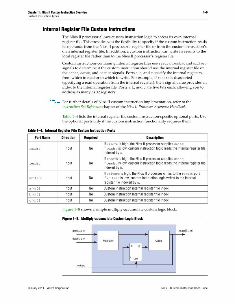
Internal Register File Custom InstructionsThe Nios II processor allows custom instruction logic to access its own internal register file. This provides you the flexibility to specify if the custom instruction reads its operands from the Nios II processor’s register file or from the custom instruction’s own internal register file. In addition, a custom instruction can write its results to the local register file rather than to the Nios II processor’s register file.
Custom instructions containing internal register files use readra, readrb, and writerc signals to determine if the custom instruction should use the internal register file or the dataa, datab, and result signals. Ports a, b, and c specify the internal registers from which to read or to which to write. For example, if readra is deasserted (specifying a read operation from the internal register), the a signal value provides an index to the internal register file. Ports a, b, and c are five bits each, allowing you to address as many as 32 registers.
f For further details of Nios II custom instruction implementation, refer to the Instruction Set Reference chapter of the Nios II Processor Reference Handbook.
Table 1–4 lists the internal register file custom instruction-specific optional ports. Use the optional ports only if the custom instruction functionality requires them.
Figure 1–8 shows a simple multiply-accumulate custom logic block.
Table 1–4. Internal Register File Custom Instruction Ports
Port Name Direction Required Description
readra Input NoIf readra is high, the Nios II processor supplies dataa;if readra is low, custom instruction logic reads the internal register file indexed by a.
readrb Input NoIf readrb is high, the Nios II processor supplies datab;if readrb is low, custom instruction logic reads the internal register file indexed by b.
writerc Input NoIf writerc is high, the Nios II processor writes to the result port;if writerc is low, custom instruction logic writes to the internal register file indexed by c.
a[4:0] Input No Custom instruction internal register file index
b[4:0] Input No Custom instruction internal register file index
c[4:0] Input No Custom instruction internal register file index
Figure 1–8. Multiply-accumulate Custom Logic Block
dataa[31..0]
datab[31..0]
writerc
result[31..0]
Multiplier Adder
D Q
CLR
January 2011 Altera Corporation Nios II Custom Instruction User Guide
1–10 Chapter 1: Nios II Custom Instruction OverviewCustom Instruction Types
When writerc is deasserted, the Nios II processor ignores the value driven on the result port. The accumulated value is stored in an internal register. Alternatively, the processor can read the value on the result port by asserting writerc. At the same time, the internal register is cleared so that it is ready for a new round of multiply and accumulate operations.
The readra, readrb, writerc, a, b, and c ports behave similarly to dataa. When the custom instruction begins, the processor presents the new values of the readra, readrb, writerc, a, b, and c ports on the rising edge of the processor clock. All six of these ports remain stable during execution of the custom instructions.
To determine how to handle the register file, custom instruction logic reads the active high readra, readrb, and writerc ports. The logic uses the a, b, and c ports as register file indexes. When readra or readrb is asserted, the custom instruction logic ignores the corresponding a or b port, and receives data from the dataa or datab port. When writerc is asserted, the custom instruction logic ignores the c port and writes to the result port.
All other custom instruction port operations behave the same as for combinational and multicycle custom instructions.
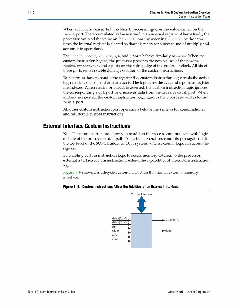
External Interface Custom InstructionsNios II custom instructions allow you to add an interface to communicate with logic outside of the processor’s datapath. At system generation, conduits propagate out to the top level of the SOPC Builder or Qsys system, where external logic can access the signals.
By enabling custom instruction logic to access memory external to the processor, external interface custom instructions extend the capabilities of the custom instruction logic.
Figure 1–9 shows a multicycle custom instruction that has an external memory interface.
Figure 1–9. Custom Instructions Allow the Addition of an External Interface
dataa[31..0] datab[31..0]
clk clk_en
reset start
Conduit Interface
done
result[31..0]
Nios II Custom Instruction User Guide January 2011 Altera Corporation

Chapter 1: Nios II Custom Instruction Overview 1–11Custom Instruction Types
Custom instruction logic can perform various tasks such as storing intermediate results or reading memory to control the custom instruction operation. The conduit interface also provides a dedicated path for data to flow into or out of the processor. For example, custom instruction logic with an external interface can feed data directly from the processor’s register file to an external first-in first-out (FIFO) memory buffer.
January 2011 Altera Corporation Nios II Custom Instruction User Guide

1–12 Chapter 1: Nios II Custom Instruction OverviewCustom Instruction Types
Nios II Custom Instruction User Guide January 2011 Altera Corporation
January 2011 Altera Corporation
2. Software Interface
The Nios II custom instruction software interface abstracts logic implementation details from the application code. During the build process the Nios II software build tools generate macros that allow easy access from application code to custom instructions.
This chapter contains the following sections:
■ “Custom Instruction Examples” on page 2–1
■ “Built-in Functions and User-defined Macros” on page 2–2
■ “Custom Instruction Assembly Software Interface” on page 2–3
Custom Instruction ExamplesExample 2–1 shows a portion of the system.h header file that defines a macro for a bit-swap custom instruction. This bit-swap example accepts one 32-bit input and performs only one function.
In Example 2–1, ALT_CI_BITWSWAP_N is defined to be 0x0, which is the custom instruction’s index. The ALT_CI_BITSWAP(A) macro is mapped to a gcc built-in function that takes a single argument.
For more information about the gcc built-in functions, refer to Appendix B, Custom Instruction Built-in Functions.
Example 2–2 illustrates application code that uses the bit-swap custom instruction.
The code in Example 2–2 includes the system.h file to enable the application software to use the custom instruction macro definition. The example code declares two integers, a and a_swap. Integer a is passed as input to the bit swap custom instruction and the results are loaded in a_swap.
Example 2–1. Bit Swap Macro Definition
#define ALT_CI_BITSWAP_N 0x00#define ALT_CI_BITSWAP(A) __builtin_custom_ini(ALT_CI_BITSWAP_N,(A))
Example 2–2. Bit Swap Instruction Usage
#include "system.h"
int main (void){
int a = 0x12345678;int a_swap = 0;
a_swap = ALT_CI_BITSWAP(a);return 0;}
Nios II Custom Instruction User Guide
2–2 Chapter 2: Software InterfaceBuilt-in Functions and User-defined Macros
Example 2–2 illustrates how most applications use custom instructions. The macros defined by the Nios II software build tools use C integer types only. Occasionally, applications require input types other than integers. In those cases, you can use a custom instruction macro to process non-integer return values.
1 You can define custom macros for Nios II custom instructions that allow other 32-bit input types to interface with custom instructions.
Built-in Functions and User-defined MacrosThe Nios II processor uses gcc built-in functions to map to custom instructions. By default, the integer type custom instruction is defined in a system.h file. However, by using built-in functions, software can use non-integer types with custom instructions. Fifty-two built-in functions are available to accommodate the different combinations of supported types.
Built-in function names have the following format:
__builtin_custom_<return type>n<parameter types>
Table 2–1 lists the 32-bit types supported by custom instructions as parameters and return types, as well as the abbreviations used in the built-in function names.
Example 2–3 shows the prototype definitions for two built-in functions.
The built-in function __builtin_custom_nf takes a float as an input, and does not return a value. In contrast, the built-in function__builtin_custom_fnp takes a pointer as input, and returns a float.
To support non-integer input types, define macros with mnemonic names that map to the specific built-in function required for the application.
f Refer to Appendix B, Custom Instruction Built-in Functions for detailed information and a list of built-in functions.
Table 2–1. 32-bit Types Supported by Custom Instructions
32-bit Type Built-in Function Abbreviation
int i
float f
void * p
Example 2–3. Two Example Built-in Function Prototypes
void __builtin_custom_nf (int n, float dataa);
float __builtin_custom_fnp (int n, void * dataa);
Nios II Custom Instruction User Guide January 2011 Altera Corporation

Chapter 2: Software Interface 2–3Custom Instruction Assembly Software Interface
Example 2–4 shows user-defined custom instruction macros used in an application.
On lines 2 through 6, the user-defined macros are declared and mapped to the appropriate built-in functions. The macro UDEF_MACRO1 takes a float as an input parameter and does not return anything. The macro UDEF_MACRO2 takes a pointer as an input parameter and returns a float. Lines 14 and 15 show code that uses the two user-defined macros.
Custom Instruction Assembly Software InterfaceThe Nios II custom instructions are also accessible in assembly code. This section describes the assembly interface.
Custom instructions are R-type instructions, containing:
■ A 6-bit opcode
■ Three 5-bit register index fields
■ Three 1-bit fields for the readra, readrb, and writerc signals
■ An 8-bit N field, used for the custom instruction index (opcode extension), and optionally including a function select subfield
Example 2–4. Custom Instruction Macro Usage Example
1. /* define void udef_macro1(float data); */2. #define UDEF_MACRO1_N 0x003. #define UDEF_MACRO1(A) __builtin_custom_nf(UDEF_MACRO1_N, (A));4. /* define float udef_macro2(void *data); */5. #define UDEF_MACRO2_N 0x016. #define UDEF_MACRO2(B) __builtin_custom_fnp(UDEF_MACRO2_N, (B));7. 8. int main (void)9. {10. float a = 1.789;11. float b = 0.0;12. float *pt_a = &a;13. 14. UDEF_MACRO1(a);15. b = UDEF_MACRO2((void *)pt_a);16. return 0;17. }
January 2011 Altera Corporation Nios II Custom Instruction User Guide
2–4 Chapter 2: Software InterfaceCustom Instruction Assembly Software Interface
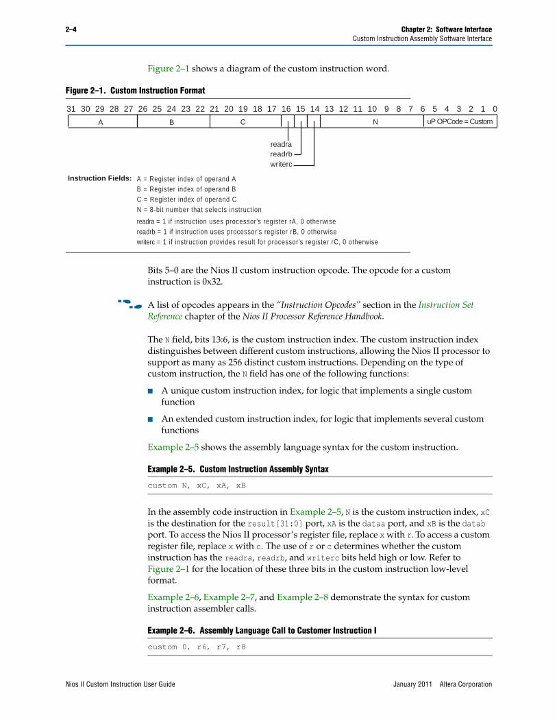
Figure 2–1 shows a diagram of the custom instruction word.
Bits 5–0 are the Nios II custom instruction opcode. The opcode for a custom instruction is 0x32.
f A list of opcodes appears in the “Instruction Opcodes” section in the Instruction Set Reference chapter of the Nios II Processor Reference Handbook.
The N field, bits 13:6, is the custom instruction index. The custom instruction index distinguishes between different custom instructions, allowing the Nios II processor to support as many as 256 distinct custom instructions. Depending on the type of custom instruction, the N field has one of the following functions:
■ A unique custom instruction index, for logic that implements a single custom function
■ An extended custom instruction index, for logic that implements several custom functions
Example 2–5 shows the assembly language syntax for the custom instruction.
In the assembly code instruction in Example 2–5, N is the custom instruction index, xC is the destination for the result[31:0] port, xA is the dataa port, and xB is the datab port. To access the Nios II processor’s register file, replace x with r. To access a custom register file, replace x with c. The use of r or c determines whether the custom instruction has the readra, readrb, and writerc bits held high or low. Refer to Figure 2–1 for the location of these three bits in the custom instruction low-level format.
Example 2–6, Example 2–7, and Example 2–8 demonstrate the syntax for custom instruction assembler calls.
Figure 2–1. Custom Instruction Format
31 30 29 28 27 26 25 24 23 22 21 20 19 18 17 16 15 14 13 12 11 10 9 8 7 6 5 4 3 2 1 0
NCBA uP OPCode = Custom
writercreadrbreadra
A = Register index of operand A B = Register index of operand BC = Register index of operand CN = 8-bit number that selects instruction
readra = 1 if instruction uses processor’s register rA, 0 otherwisereadrb = 1 if instruction uses processor’s register rB, 0 otherwisewriterc = 1 if instruction prov ides result for processor’s register rC, 0 otherwise
Instruction Fields:
Example 2–5. Custom Instruction Assembly Syntax
custom N, xC, xA, xB
Example 2–6. Assembly Language Call to Customer Instruction I
custom 0, r6, r7, r8
Nios II Custom Instruction User Guide January 2011 Altera Corporation
Chapter 2: Software Interface 2–5Custom Instruction Assembly Software Interface
Example 2–6 shows a call to a custom instruction with index 0. The input to the instruction is the current contents of the Nios II processor registers r7 and r8, and the results are stored in the Nios II processor register r6.
Example 2–7 shows a call to a custom instruction with index 3. The input to the instruction is the current contents of the Nios II processor register r2 and the custom register c4, and the results are stored in custom register c1.
Example 2–8 shows a call to a custom instruction with index 4. The input to the instruction is the current contents of the custom register c9 and the Nios II processor register r2, and the results are stored in Nios II processor register r6.
f For more information about the binary format of custom instructions, refer to the Instruction Set Reference chapter of the Nios II Processor Reference Handbook.
Example 2–7. Assembly Language Call to Customer Instruction II
custom 3, c1, r2, c4
Example 2–8. Assembly Language Call to Customer Instruction III
custom 4, r6, c9, r2
January 2011 Altera Corporation Nios II Custom Instruction User Guide

2–6 Chapter 2: Software InterfaceCustom Instruction Assembly Software Interface
Nios II Custom Instruction User Guide January 2011 Altera Corporation
January 2011 Altera Corporation
3. Implementing a Nios II CustomInstruction in SOPC Builder
This chapter describes the process of implementing a Nios II custom instruction with the SOPC Builder component editor. The component editor enables you to create new SOPC Builder components, including Nios II custom instructions. This chapter also describes the process of accessing Nios II custom instructions from software.
f For detailed information about the SOPC Builder component editor, refer to the “Component Editor” chapter of the SOPC Builder User Guide.
Design Example: Cyclic Redundancy CheckThe cyclic redundancy check (CRC) algorithm detects the corruption of data during transmission. It detects a higher percentage of errors than a simple checksum. The CRC calculation consists of an iterative algorithm involving XOR and shift operations. These operations are carried out concurrently in hardware and iteratively in software. Because the operations are carried out concurrently, the execution is much faster in hardware.
The CRC design files demonstrate the steps to implement an extended multicycle Nios II custom instruction. These design files are available for you to download from the Nios II Custom Instruction Design Example web page.
Implementing Custom Instruction Hardware in SOPC BuilderThis section describes the custom instruction tool-flow, and walks you through the process of implementing a Nios II custom instruction. Implementing a Nios II custom instruction hardware entails the following tasks:
■ “Opening the Component Editor”
■ “Adding the HDL Files”
■ “Configuring the Custom Instruction Signal Type” on page 3–3
■ “Setting Up the Custom Instruction Interfaces” on page 3–3
■ “Setting the Details” on page 3–4
■ “Saving and Adding the Custom Instruction” on page 3–5
■ “Generating the System and Compiling in the Quartus II Software” on page 3–5
The following sections detail the steps required to set up the design example environment and to perform the list of tasks.
Nios II Custom Instruction User Guide
3–2 Chapter 3: Implementing a Nios II Custom Instruction in SOPC BuilderImplementing Custom Instruction Hardware in SOPC Builder
Setting up the Design Environment for the Design ExampleBefore you start the design example, you must set up the design environment to accommodate the processes described in the following sections. To set up the design example environment, follow these steps:
1. Open the ug_custom_instruction_files.zip file from the Nios II Custom Instruction Design Example web page and extract all the files to a new directory.
2. Follow the instructions in the Quartus II Project Setup section in the readme_sopcb.txt file in the extracted design files. The instructions direct you to determine a <project_dir> working directory for the project, to download an appropriate Quartus II project for your development board, and to open the design example project in the Quartus II software.
Opening the Component EditorAfter you follow the steps in the Quartus II Project Setup section of the readme_sopcb.txt file, you have an Quartus II project located in the <project_dir> directory and open in the Quartus II software.
To open the component editor, follow these steps:
1. To open the SOPC Builder system, on the Tools menu, click SOPC Builder.
2. On the SOPC Builder System Contents tab, double-click cpu. The Nios II Processor parameter editor appears.
3. On the Parameter Settings page, on the Custom Instructions tab, click Import. The component editor appears, displaying the Introduction tab.
Adding the HDL FilesTo specify the synthesis HDL files for your custom instruction, follow these steps:
1. Click Next to display the HDL Files tab.
2. Click Add.
3. Browse to <project_dir>/crc_hw, the location of the HDL files for this design example.
4. Select the CRC_Custom_Instruction.v and CRC_Component.v files and click Open.
1 The Quartus II Analysis and Synthesis program checks the design for errors when you add the files. Confirm that no error message appears.
5. Ensure the Synth setting is turned on for both files. This setting directs the component editor to generate models for synthesis.
6. Turn on the Top parameter for the CRC_Custom_Instruction.v file, to indicate it is the top-level HDL file for this custom instruction.
1 The Quartus II Analysis and Synthesis program checks the design for errors when you change the Top setting. Confirm that no error message appears.
Nios II Custom Instruction User Guide January 2011 Altera Corporation
Chapter 3: Implementing a Nios II Custom Instruction in SOPC Builder 3–3Implementing Custom Instruction Hardware in SOPC Builder
7. Click Top Level Module and select the name of the top-level module of your custom instruction logic. The top-level module for this design example is CRC_Custom_Instruction.
8. To enable simulating the system in the ModelSim simulator, you can turn on Sim for both files. In cases other than the design example, you may need to add additional simulation files in the component editor HDL Files tab, turn on Sim and turn off Synth for these simulation-only files, and turn off Sim for the synthesis-only files.
Configuring the Custom Instruction Signal TypeTo configure the custom instruction signal type, follow these steps:
1. Click Next to display the Signals tab.
2. For each port listed in the tab, follow these steps:
a. Select the port.
b. In the Interface column, select the name of the interface to which you want to assign the port. For the design example, select nios_custom_instruction_slave_0.
c. In the Signal Type column, select the appropriate signal type for the port. The available types are described in “Custom Instruction Types” on page 1–3.
Setting Up the Custom Instruction InterfacesTo set up the custom instruction interfaces, follow these steps:
1. Click Next to display the Interfaces tab.
2. For Type, select Custom Instruction Slave.
3. For the design example, maintain the interface name nios_custom_instruction_slave_0.
1 If you rename an interface by changing the value in the Name field, the Signals tab Interface column value changes automatically. The value shown in the block diagram updates when you change tabs and return to the Interfaces tab.
4. For Clock Cycles, type 0 for a variable multicycle type custom instruction, and otherwise type the number of clock cycles your custom instruction logic requires. The design example builds a variable multicycle type custom instruction.
1 If the interface includes a done signal and a clk signal, the component editor automatically infers that the interface is a variable multicycle type custom instruction interface, and sets the value to 0.
5. For Clock Cycle Type, type Variable for a variable multicycle type custom instruction, Multicycle for a fixed multicycle type custom instruction, or Combinatorial for a combinational type custom instruction.
January 2011 Altera Corporation Nios II Custom Instruction User Guide
3–4 Chapter 3: Implementing a Nios II Custom Instruction in SOPC BuilderImplementing Custom Instruction Hardware in SOPC Builder
1 If the interface does not include a clk signal, the component editor automatically infers that the interface is a combinational type interface. If the interface includes a clk signal, the component editor automatically infers that the interface is a multicycle interface. If the interface does not include a done signal, the component editor infers that the interface is a fixed multicycle type interface. If the interface includes a done signal, the component editor infers that the interface is a variable multicycle type interface.
6. For Operands, type the number of operands for your custom instruction. For the design example, type 1.
7. If the warning message Interface has no signals appears, click Remove Interfaces With No Signals.
If your custom instruction logic requires additional interfaces, either to the Avalon-MM fabric or outside the SOPC Builder system, you can specify the additional interfaces in the Interfaces tab. The design example does not require additional interfaces.
1 Most custom instructions use some combination of standard custom instruction ports, such as dataa, datab, and result, and do not require additional interfaces.
The following instructions provide the information you need if a custom instruction in your own design requires additional interfaces. If you are walking through the design example, proceed to “Setting the Details”.
To specify additional interfaces on the Interfaces tab, follow these steps:
1. Click Add Interface. The new interface has Custom Instruction Slave interface type by default.
2. For Type, select the desired interface type.
3. Set the parameters for the newly created interface according to your system requirements.
Setting the DetailsTo specify the final details in the custom instruction parameter editor, follow these steps:
1. Click Next to display the HDL Parameters tab.
2. Click Next to display the Library Info tab.
3. For Name and for Display Name, type CRC.
4. For Version, type 1.0.
5. Leave the Group field blank.
6. Optionally, set the Description, Created by, and Icon fields as you prefer.
7. If the bottom pane of the dialog box displays something other than the message Info: No errors or warnings, review the other tabs to ensure you followed the instructions correctly.
Nios II Custom Instruction User Guide January 2011 Altera Corporation
Chapter 3: Implementing a Nios II Custom Instruction in SOPC Builder 3–5Implementing Custom Instruction Hardware in SOPC Builder
Saving and Adding the Custom InstructionTo save the custom instruction and add it to your Nios II processor, follow these steps:
1. Click Finish. A dialog box prompts you to save your changes before exiting.
2. Click Yes, Save. In the Nios II processor parameter editor, on the Custom Instructions tab, the new custom instruction appears in the left panel.
3. If the new custom instruction does not appear on the Custom Instructions tab in the left panel, follow these steps:
a. Click Finish to exit the Nios II processor parameter editor.
b. On the SOPC Builder System Contents tab, double-click cpu to reopen the Nios II parameter editor.
4. In the left panel of the Custom Instructions tab, select CRC, the new custom instruction you created in the design example.
5. Click Add to add the new instruction to the Nios II processor. Information about the new instruction appears in the right panel, listing the name, Clock Cycles value, N Port information, and Opcode Extension.
If the custom instruction is an extended type instruction, the N Port field specifies the function select bits in the N port. Otherwise, the N Port field contains a dash.
The Opcode Extension field displays the custom instruction index (N field) of the instruction word in both binary and decimal formats. For more information about the N field, refer to “Custom Instruction Assembly Software Interface” on page 2–3.
6. Click Finish to complete the addition of the custom instruction to the SOPC Builder system and return to SOPC Builder.
Generating the System and Compiling in the Quartus II SoftwareAfter you add the custom instruction logic to the system, you can generate the system and compile it in the Quartus II software. During system generation, SOPC Builder connects the custom logic to the Nios II processor.
To generate the system and compile, follow these steps:
1. In SOPC Builder, on the System Generation tab, turn on Simulation. Create project simulator files if you want to simulate your system.
2. Click Generate. System generation may take several seconds to complete.
3. After system generation completes, click Exit.
4. In the Quartus II software, on the Processing menu, click Start Compilation.
f For detailed information about SOPC Builder systems and their generation, refer to the SOPC Builder User Guide or the SOPC Builder Help system.
January 2011 Altera Corporation Nios II Custom Instruction User Guide
3–6 Chapter 3: Implementing a Nios II Custom Instruction in SOPC BuilderAccessing the Custom Instruction from Software
Accessing the Custom Instruction from SoftwareAdding a custom instruction to a Nios II processor results in a significant change to the SOPC Builder system. In this section, you create and build a new software project using the Nios II software build flow, and run the software that accesses the custom instruction. The software source files are included in the downloadable design files.
Table 3–1 lists the CRC application software source files and their corresponding descriptions.
To run the application software, you must create an Executable and Linking Format File (.elf) first. To create the .elf file, follow the instructions in the Nios II Software Build Flow section in the readme_sopcb.txt file in the extracted design files.
The application program runs three implementations of the CRC algorithm on the same pseudo-random input data: an unoptimized software implementation, an optimized software implementation, and the custom instruction CRC. The program calculates the processing time and throughput for each of the versions, to demonstrate the improved efficiency of a custom instruction compared to a software implementation.
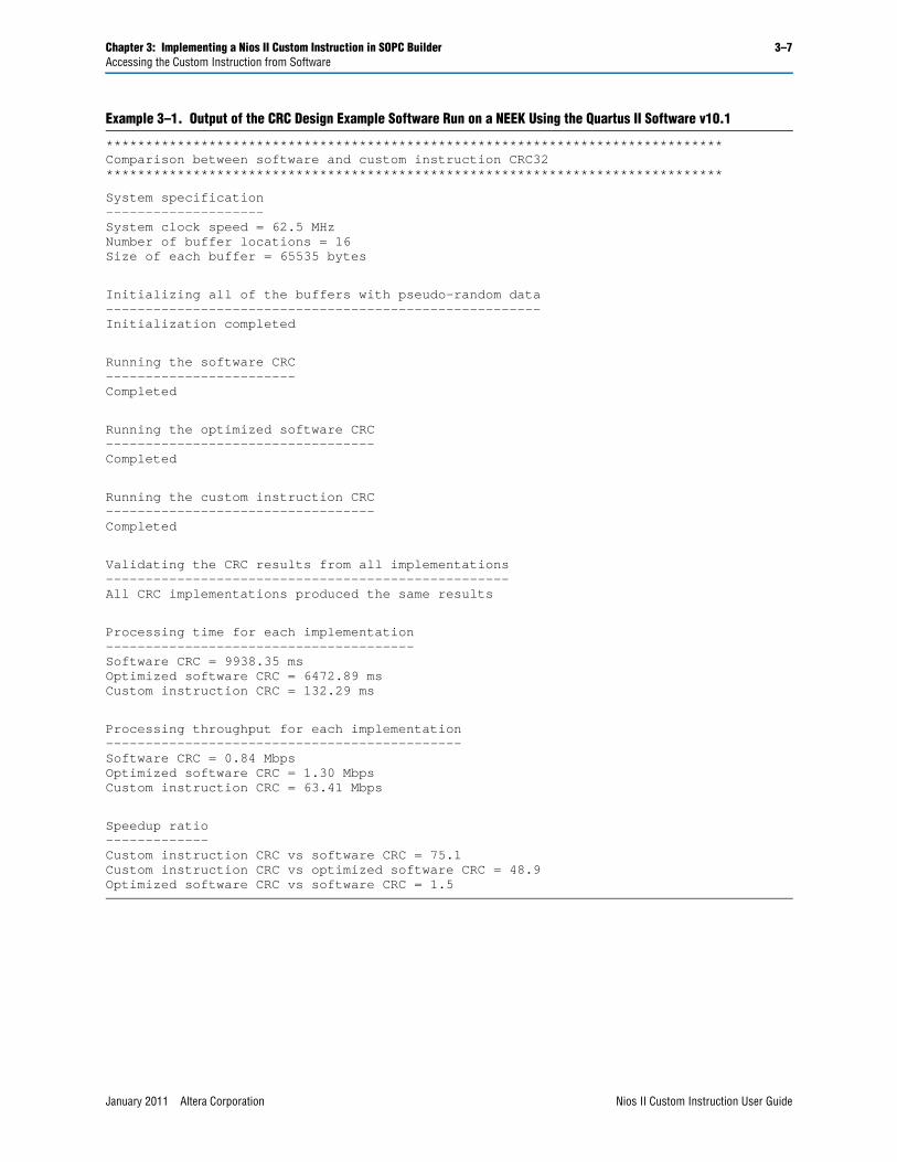
Example 3–1 shows the output from the application program run on a Nios II Embedded Evaluation Kit, Cyclone III Edition (NEEK) using the Quartus II software v10.1 and Nios II Embedded Design Suite (EDS) v10.1.
The output shows that the custom instruction CRC is 75 times faster than the unoptimized CRC calculated purely in software and is almost 50 times faster than the optimized version of the software CRC. The results you see using different target device and board may vary depending on the memory characteristics of the board and the clock speed of the device, but these ratios are representative.
Table 3–1. CRC Application Software Source Files
File Name Description
crc_main.cMain program that populates random test data, executes the CRC both in software and with the custom instruction, validates the output, and reports the processing time.
crc.c Software CRC algorithm run by the Nios II processor.
crc.h Header file for crc.c.
ci_crc.c Program that accesses CRC custom instruction.
ci_crc.h Header file for ci_crc.c.
Nios II Custom Instruction User Guide January 2011 Altera Corporation
Chapter 3: Implementing a Nios II Custom Instruction in SOPC Builder 3–7Accessing the Custom Instruction from Software
Example 3–1. Output of the CRC Design Example Software Run on a NEEK Using the Quartus II Software v10.1
******************************************************************************Comparison between software and custom instruction CRC32******************************************************************************
System specification--------------------System clock speed = 62.5 MHzNumber of buffer locations = 16Size of each buffer = 65535 bytes
Initializing all of the buffers with pseudo-random data-------------------------------------------------------Initialization completed
Running the software CRC------------------------Completed
Running the optimized software CRC----------------------------------Completed
Running the custom instruction CRC----------------------------------Completed
Validating the CRC results from all implementations---------------------------------------------------All CRC implementations produced the same results
Processing time for each implementation---------------------------------------Software CRC = 9938.35 msOptimized software CRC = 6472.89 msCustom instruction CRC = 132.29 ms
Processing throughput for each implementation---------------------------------------------Software CRC = 0.84 MbpsOptimized software CRC = 1.30 MbpsCustom instruction CRC = 63.41 Mbps
Speedup ratio-------------Custom instruction CRC vs software CRC = 75.1Custom instruction CRC vs optimized software CRC = 48.9Optimized software CRC vs software CRC = 1.5
January 2011 Altera Corporation Nios II Custom Instruction User Guide
3–8 Chapter 3: Implementing a Nios II Custom Instruction in SOPC BuilderUsing the User-defined Custom Instruction Macro
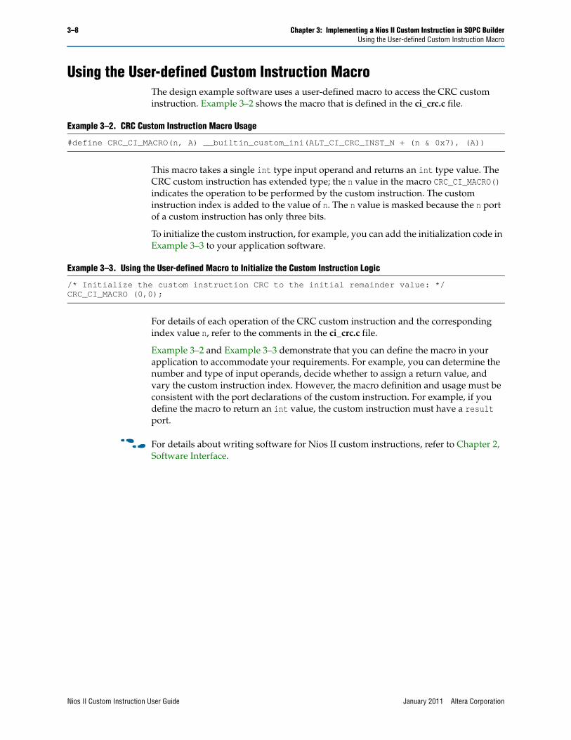
Using the User-defined Custom Instruction MacroThe design example software uses a user-defined macro to access the CRC custom instruction. Example 3–2 shows the macro that is defined in the ci_crc.c file.
This macro takes a single int type input operand and returns an int type value. The CRC custom instruction has extended type; the n value in the macro CRC_CI_MACRO() indicates the operation to be performed by the custom instruction. The custom instruction index is added to the value of n. The n value is masked because the n port of a custom instruction has only three bits.
To initialize the custom instruction, for example, you can add the initialization code in Example 3–3 to your application software.
For details of each operation of the CRC custom instruction and the corresponding index value n, refer to the comments in the ci_crc.c file.
Example 3–2 and Example 3–3 demonstrate that you can define the macro in your application to accommodate your requirements. For example, you can determine the number and type of input operands, decide whether to assign a return value, and vary the custom instruction index. However, the macro definition and usage must be consistent with the port declarations of the custom instruction. For example, if you define the macro to return an int value, the custom instruction must have a result port.
f For details about writing software for Nios II custom instructions, refer to Chapter 2, Software Interface.
Example 3–2. CRC Custom Instruction Macro Usage
#define CRC_CI_MACRO(n, A) __builtin_custom_ini(ALT_CI_CRC_INST_N + (n & 0x7), (A))
Example 3–3. Using the User-defined Macro to Initialize the Custom Instruction Logic
/* Initialize the custom instruction CRC to the initial remainder value: */CRC_CI_MACRO (0,0);
Nios II Custom Instruction User Guide January 2011 Altera Corporation
January 2011 Altera Corporation
4. Implementing a Nios II CustomInstruction in Qsys
This chapter describes the process of implementing a Nios II custom instruction with the Qsys component editor. The component editor enables you to create new Qsys components, including Nios II custom instructions. This chapter also describes the process of accessing Nios II custom instructions from software.
f For detailed information about the Qsys component editor, refer to Creating Qsys Components in volume 1 of the Quartus II Handbook.
Design Example: Cyclic Redundancy Check The cyclic redundancy check (CRC) algorithm detects the corruption of data during transmission. It detects a higher percentage of errors than a simple checksum. The CRC calculation consists of an iterative algorithm involving XOR and shift operations. These operations are carried out concurrently in hardware and iteratively in software. Because the operations are carried out concurrently, the execution is much faster in hardware.
The CRC design files demonstrate the steps to implement an extended multicycle Nios II custom instruction. These design files are available for you to download from the Nios II Custom Instruction Design Example web page.
Implementing Custom Instruction Hardware in QsysThis section describes the custom instruction tool-flow, and walks you through the process of implementing a Nios II custom instruction. Implementing a Nios II custom instruction hardware entails the following tasks:
■ “Opening the Component Editor”
■ “Adding the HDL Files”
■ “Configuring the Custom Instruction Signal Type” on page 4–3
■ “Setting Up the Custom Instruction Interfaces” on page 4–3
■ “Setting the Details” on page 4–4
■ “Saving and Adding the Custom Instruction” on page 4–5
■ “Generating the System and Compiling in the Quartus II Software” on page 4–5
The following sections detail the steps required to set up the design example environment and to perform the list of tasks.
Nios II Custom Instruction User Guide
4–2 Chapter 4: Implementing a Nios II Custom Instruction in QsysImplementing Custom Instruction Hardware in Qsys
Setting up the Design Environment for the Design ExampleBefore you start the design example, you must set up the design environment to accommodate the processes described in the following sections. To set up the design example environment, follow these steps:
1. Open the ug_custom_instruction_files.zip file from the Nios II Custom Instruction Design Example web page and extract all the files to a new directory.
2. Follow the instructions in the Quartus II Project Setup section in the readme_qsys.txt file in the extracted design files. The instructions direct you to determine a <project_dir> working directory for the project and to open the design example project in the Quartus II software.
Opening the Component EditorAfter you follow the steps in the Quartus II Project Setup section of the readme_qsys.txt file, you have an Quartus II project located in the <project_dir> directory and open in the Quartus II software.
To open the component editor, follow these steps:
1. To open Qsys, on the Tools menu, click Qsys.
2. In Qsys, on the File menu, click Open.
3. Browse to the <project_dir> directory if necessary, select the .qsys file, and click Open.
4. On the Qsys Component Library tab, click New. The component editor appears, displaying the Introduction tab.
Adding the HDL FilesTo specify the synthesis HDL files for your custom instruction, follow these steps:
1. Click Next to display the HDL Files tab.
2. Click Add.
3. Browse to <project_dir>/crc_hw, the location of the HDL files for this design example.
4. Select the CRC_Custom_Instruction.v and CRC_Component.v files and click Open.
1 The Quartus II Analysis and Synthesis program checks the design for errors when you add the files. Confirm that no error message appears.
5. Ensure the Synth setting is turned on for both files. This setting directs the component editor to generate models for synthesis..
6. Turn on the Top parameter for the CRC_Custom_Instruction.v file, to indicate it is the top-level HDL file for this custom instruction.
1 The Quartus II Analysis and Synthesis program checks the design for errors when you change the Top setting. Confirm that no error message appears.
Nios II Custom Instruction User Guide January 2011 Altera Corporation
Chapter 4: Implementing a Nios II Custom Instruction in Qsys 4–3Implementing Custom Instruction Hardware in Qsys
7. Click Top Level Module and select the name of the top-level module of your custom instruction logic. The top-level module for this design example is CRC_Custom_Instruction.
8. To enable simulating the system in the ModelSim simulator, you can turn on Sim for both files. In cases other than the design example, you may need to add additional simulation files in the component editor HDL Files tab, turn on Sim and turn off Synth for these simulation-only files, and turn off Sim for the synthesis-only files.
Configuring the Custom Instruction Signal TypeTo configure the custom instruction signal type, follow these steps:
1. Click Next to display the Signals tab.
2. For each port listed in the tab, follow these steps:
a. Select the port.
b. In the Interface column, select the name of the interface to which you want to assign the port.
For the design example, for the first port you configure, select New Custom Instruction Slave. For the remaining ports, select the name created for the first port, which is nios_custom_instruction_slave. These selections ensure that the ports appear together on a single interface, using the name assumed by the design example crc_hw files.
c. In the Signal Type column, select the appropriate signal type for the port. The available signal types are described in “Custom Instruction Types” on page 1–3. In the design example, the correct signal type for each signal has the same name as the signal.
Setting Up the Custom Instruction InterfacesTo set up the custom instruction interfaces, follow these steps:
1. Click Next to display the Interfaces tab.
2. If the Remove Interfaces With No Signals button is active, click it.
3. Ensure that a single interface remains, with Name set to the name in the Signals tab. For the design example, maintain the interface name nios_custom_instruction_slave.
1 If you rename an interface by changing the value in the Name field, the Signals tab Interface column value changes automatically. The value shown in the block diagram updates when you change tabs and return to the Interfaces tab.
4. Ensure the Type for this interface is Custom Instruction Slave.
5. For Clock Cycles, type 0 for a variable multicycle type custom instruction, and otherwise type the number of clock cycles your custom instruction logic requires. The design example builds a variable multicycle type custom instruction.
January 2011 Altera Corporation Nios II Custom Instruction User Guide
4–4 Chapter 4: Implementing a Nios II Custom Instruction in QsysImplementing Custom Instruction Hardware in Qsys
1 If the interface includes a done signal and a clk signal, the component editor automatically infers that the interface is a variable multicycle type custom instruction interface, and sets the value to 0.
6. For Clock Cycle Type, type Variable for a variable multicycle type custom instruction, Multicycle for a fixed multicycle type custom instruction, or Combinatorial for a combinational type custom instruction. Because the design example builds a variable multicycle type custom instruction, Clock Cycle Type is set to Variable.
1 If the interface does not include a clk signal, the component editor automatically infers that the interface is a combinational type interface. If the interface includes a clk signal, the component editor automatically infers that the interface is a multicycle interface. If the interface does not include a done signal, the component editor infers that the interface is a fixed multicycle type interface. If the interface includes a done signal, the component editor infers that the interface is a variable multicycle type interface.
7. For Operands, type the number of operands for your custom instruction. For the design example, type 1.
If your custom instruction logic requires additional interfaces, either to the Avalon-MM fabric or outside the Qsys system, you can specify the additional interfaces in the Interfaces tab. The design example does not require additional interfaces.
1 Most custom instructions use some combination of standard custom instruction ports, such as dataa, datab, and result, and do not require additional interfaces.
The following instructions provide the information you need if a custom instruction in your own design requires additional interfaces. If you are walking through the design example, proceed to “Setting the Details”.
To specify additional interfaces on the Interfaces tab, follow these steps:
1. Click Add Interface. The new interface has Custom Instruction Slave interface type by default.
2. For Type, select the desired interface type.
3. Set the parameters for the newly created interface according to your system requirements.
Setting the DetailsTo specify the final details in the custom instruction parameter editor, follow these steps:
1. Click Next to display the HDL Parameters tab.
2. Click Next to display the Library Info tab.
3. For Name and for Display Name, type CRC.
4. For Version, type 1.0.
Nios II Custom Instruction User Guide January 2011 Altera Corporation
Chapter 4: Implementing a Nios II Custom Instruction in Qsys 4–5Accessing the Custom Instruction from Software
5. Leave the Group field blank.
6. Optionally, set the Description, Created by, and Icon fields as you prefer.
7. If the bottom pane of the dialog box displays something other than the message Info: No errors or warnings, review the other tabs to ensure you followed the instructions correctly.
Saving and Adding the Custom InstructionTo save the custom instruction and add it to your Nios II processor, follow these steps:
1. Click Finish. A dialog box prompts you to save your changes before exiting.
2. Click Yes, Save. The new custom instruction appears in the Qsys Component Library.
3. In the Qsys Component Library, under Library, select CRC, the new custom instruction you created in the design example.
4. Click Add to add the new instruction to the Qsys system.
5. In the Connections panel, connect the new CRC_0 component’s nios_custom_instruction_slave interface to the cpu component’s custom_instruction_master interface.
Generating the System and Compiling in the Quartus II SoftwareAfter you add the custom instruction logic to the system, you can generate the Qsys system and compile it in the Quartus II software.
To generate the system and compile, follow these steps:
1. In Qsys, on the Generation tab, turn on Create HDL design files for synthesis.
2. Click Generate. System generation may take several seconds to complete.
3. After system generation completes, on the File menu, click Exit.
4. In the Quartus II software, on the Project menu, click Add/Remove Files in Project.
5. Ensure that the .qip file in the synthesis subdirectory is added to the project.
6. On the Processing menu, click Start Compilation.
f For detailed information about Qsys systems and their generation, refer to the System Design with Qsys section in volume 1 of the Quartus II Handbook.
Accessing the Custom Instruction from SoftwareAdding a custom instruction to a Nios II processor results in a significant change to the Qsys system. In this section, you create and build a new software project using the Nios II software build flow, and run the software that accesses the custom instruction. The software source files are included in the downloadable design files.
January 2011 Altera Corporation Nios II Custom Instruction User Guide

4–6 Chapter 4: Implementing a Nios II Custom Instruction in QsysAccessing the Custom Instruction from Software
Table 4–1 lists the CRC application software source files and their corresponding descriptions.
To run the application software, you must create an Executable and Linking Format File (.elf) first. To create the .elf file, follow the instructions in the Nios II Software Build Flow section in the readme_qsys.txt file in the extracted design files.
The application program runs three implementations of the CRC algorithm on the same pseudo-random input data: an unoptimized software implementation, an optimized software implementation, and the custom instruction CRC. The program calculates the processing time and throughput for each of the versions, to demonstrate the improved efficiency of a custom instruction compared to a software implementation.
Example 4–1 shows the output from the application program run on a Nios II Embedded Evaluation Kit, Cyclone III Edition (NEEK) using the Quartus II software v10.1 Service Pack 1 and Nios II Embedded Design Suite (EDS) v10.1 Service Pack 1.
The output shows that the custom instruction CRC is more than 70 times faster than the unoptimized CRC calculated purely in software and is more than 45 times faster than the optimized version of the software CRC. The results you see using different target device and board may vary depending on the memory characteristics of the board and the clock speed of the device, but these ratios are representative.
Table 4–1. CRC Application Software Source Files
File Name Description
crc_main.cMain program that populates random test data, executes the CRC both in software and with the custom instruction, validates the output, and reports the processing time.
crc.c Software CRC algorithm run by the Nios II processor.
crc.h Header file for crc.c.
ci_crc.c Program that accesses CRC custom instruction.
ci_crc.h Header file for ci_crc.c.
Nios II Custom Instruction User Guide January 2011 Altera Corporation

Chapter 4: Implementing a Nios II Custom Instruction in Qsys 4–7Accessing the Custom Instruction from Software
Example 4–1. Output of the CRC Design Example Software Run on a NEEK Using the Quartus II Software v10.1 SP1
******************************************************************************Comparison between software and custom instruction CRC32******************************************************************************
System specification--------------------System clock speed = 62.5 MHzNumber of buffer locations = 16Size of each buffer = 65535 bytes
Initializing all of the buffers with pseudo-random data-------------------------------------------------------Initialization completed
Running the software CRC------------------------Completed
Running the optimized software CRC----------------------------------Completed
Running the custom instruction CRC----------------------------------Completed
Validating the CRC results from all implementations---------------------------------------------------All CRC implementations produced the same results
Processing time for each implementation---------------------------------------Software CRC = 9928.41 msOptimized software CRC = 6414.63 msCustom instruction CRC = 137.54 ms
Processing throughput for each implementation---------------------------------------------Software CRC = 0.84 MbpsOptimized software CRC = 1.31 MbpsCustom instruction CRC = 60.99 Mbps
Speedup ratio-------------Custom instruction CRC vs software CRC = 72.2Custom instruction CRC vs optimized software CRC = 46.6Optimized software CRC vs software CRC = 1.5
January 2011 Altera Corporation Nios II Custom Instruction User Guide

4–8 Chapter 4: Implementing a Nios II Custom Instruction in QsysUsing the User-defined Custom Instruction Macro
Using the User-defined Custom Instruction MacroThe design example software uses a user-defined macro to access the CRC custom instruction. Example 4–2 shows the macro that is defined in the ci_crc.c file.
This macro takes a single int type input operand and returns an int type value. The CRC custom instruction has extended type; the n value in the macro CRC_CI_MACRO() indicates the operation to be performed by the custom instruction. The custom instruction index is added to the value of n. The n value is masked because the n port of a custom instruction has only three bits.
To initialize the custom instruction, for example, you can add the initialization code in Example 4–3 to your application software.
For details of each operation of the CRC custom instruction and the corresponding index value n, refer to the comments in the ci_crc.c file.
Example 4–2 and Example 4–3 demonstrate that you can define the macro in your application to accommodate your requirements. For example, you can determine the number and type of input operands, decide whether to assign a return value, and vary the custom instruction index. However, the macro definition and usage must be consistent with the port declarations of the custom instruction. For example, if you define the macro to return an int value, the custom instruction must have a result port.
f For details about writing software for Nios II custom instructions, refer to Chapter 2, Software Interface.
Example 4–2. CRC Custom Instruction Macro Usage
#define CRC_CI_MACRO(n, A) __builtin_custom_ini(ALT_CI_CRC_0_N + (n & 0x7), (A))
Example 4–3. Using the User-defined Macro to Initialize the Custom Instruction Logic
/* Initialize the custom instruction CRC to the initial remainder value: */CRC_CI_MACRO (0,0);
Nios II Custom Instruction User Guide January 2011 Altera Corporation
January 2011 Altera Corporation
A. Custom Instruction Templates
This appendix provides VHDL and Verilog HDL custom instruction wrapper file templates that you can reference when writing custom instructions in VHDL and Verilog HDL.
f Full sets of template files are available in the <nios2eds installation directory>/examples/verilog/custom_instruction_templates and <nios2eds installation directory>/examples/vhdl/custom_instruction_templates directories.
Nios II Custom Instruction User Guide
A–2 Appendix A: Custom Instruction TemplatesVHDL Custom Instruction Template
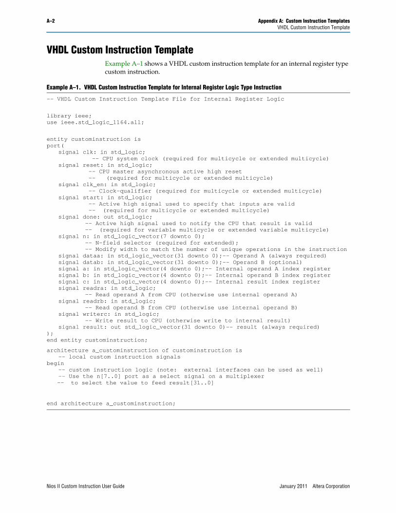
VHDL Custom Instruction Template Example A–1 shows a VHDL custom instruction template for an internal register type custom instruction.
Example A–1. VHDL Custom Instruction Template for Internal Register Logic Type Instruction
-- VHDL Custom Instruction Template File for Internal Register Logic
library ieee;use ieee.std_logic_1164.all;
entity custominstruction isport(
signal clk: in std_logic;-- CPU system clock (required for multicycle or extended multicycle)
signal reset: in std_logic;-- CPU master asynchronous active high reset -- (required for multicycle or extended multicycle)
signal clk_en: in std_logic;-- Clock-qualifier (required for multicycle or extended multicycle)
signal start: in std_logic;-- Active high signal used to specify that inputs are valid -- (required for multicycle or extended multicycle)
signal done: out std_logic;-- Active high signal used to notify the CPU that result is valid -- (required for variable multicycle or extended variable multicycle)
signal n: in std_logic_vector(7 downto 0);-- N-field selector (required for extended);-- Modify width to match the number of unique operations in the instruction
signal dataa: in std_logic_vector(31 downto 0);-- Operand A (always required)signal datab: in std_logic_vector(31 downto 0);-- Operand B (optional)signal a: in std_logic_vector(4 downto 0);-- Internal operand A index registersignal b: in std_logic_vector(4 downto 0);-- Internal operand B index registersignal c: in std_logic_vector(4 downto 0);-- Internal result index registersignal readra: in std_logic;
-- Read operand A from CPU (otherwise use internal operand A)signal readrb: in std_logic;
-- Read operand B from CPU (otherwise use internal operand B)signal writerc: in std_logic;
-- Write result to CPU (otherwise write to internal result)signal result: out std_logic_vector(31 downto 0)-- result (always required)
);end entity custominstruction;
architecture a_custominstruction of custominstruction is-- local custom instruction signals
begin-- custom instruction logic (note: external interfaces can be used as well)-- Use the n[7..0] port as a select signal on a multiplexer -- to select the value to feed result[31..0]
end architecture a_custominstruction;
Nios II Custom Instruction User Guide January 2011 Altera Corporation
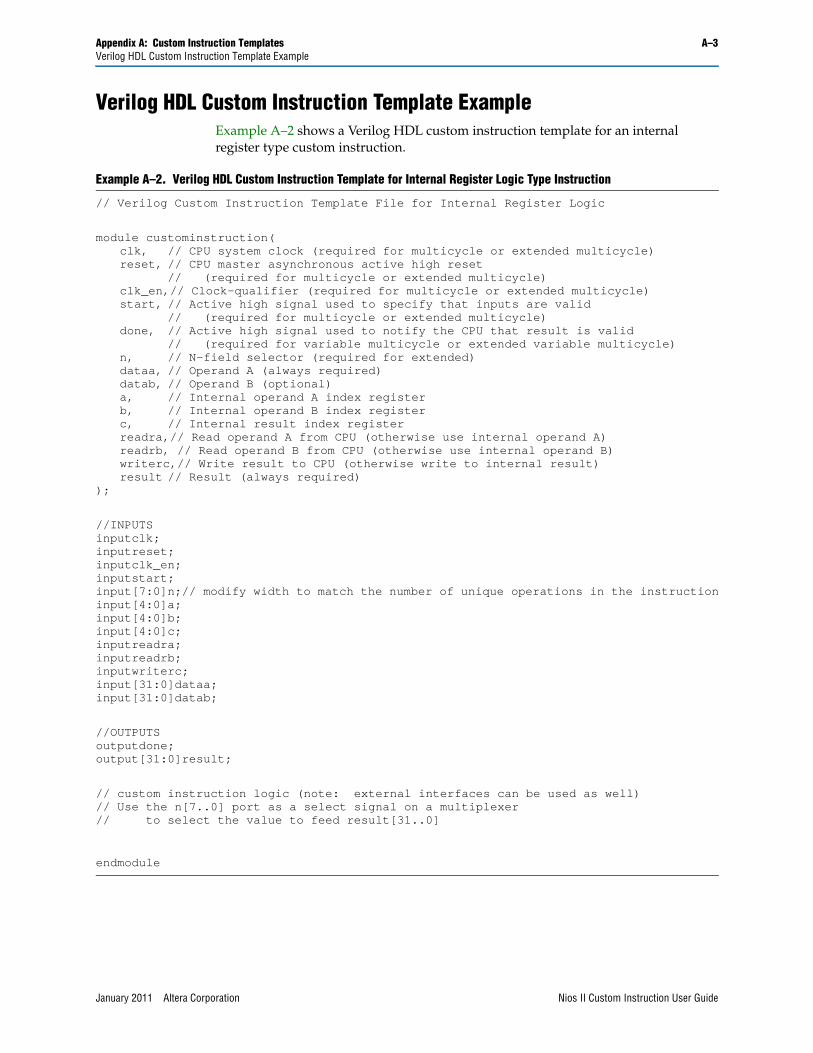
Appendix A: Custom Instruction Templates A–3Verilog HDL Custom Instruction Template Example
Verilog HDL Custom Instruction Template ExampleExample A–2 shows a Verilog HDL custom instruction template for an internal register type custom instruction.
Example A–2. Verilog HDL Custom Instruction Template for Internal Register Logic Type Instruction
// Verilog Custom Instruction Template File for Internal Register Logic
module custominstruction(clk, // CPU system clock (required for multicycle or extended multicycle)reset, // CPU master asynchronous active high reset
// (required for multicycle or extended multicycle)clk_en,// Clock-qualifier (required for multicycle or extended multicycle)start, // Active high signal used to specify that inputs are valid
// (required for multicycle or extended multicycle)done, // Active high signal used to notify the CPU that result is valid
// (required for variable multicycle or extended variable multicycle)n, // N-field selector (required for extended)dataa, // Operand A (always required)datab, // Operand B (optional)a, // Internal operand A index registerb, // Internal operand B index registerc, // Internal result index registerreadra,// Read operand A from CPU (otherwise use internal operand A)readrb, // Read operand B from CPU (otherwise use internal operand B)writerc,// Write result to CPU (otherwise write to internal result)result // Result (always required)
);
//INPUTSinputclk;inputreset;inputclk_en;inputstart;input[7:0]n;// modify width to match the number of unique operations in the instructioninput[4:0]a;input[4:0]b;input[4:0]c;inputreadra;inputreadrb;inputwriterc;input[31:0]dataa;input[31:0]datab;
//OUTPUTSoutputdone;output[31:0]result;
// custom instruction logic (note: external interfaces can be used as well)// Use the n[7..0] port as a select signal on a multiplexer // to select the value to feed result[31..0]
endmodule
January 2011 Altera Corporation Nios II Custom Instruction User Guide

A–4 Appendix A: Custom Instruction TemplatesVerilog HDL Custom Instruction Template Example
Nios II Custom Instruction User Guide January 2011 Altera Corporation
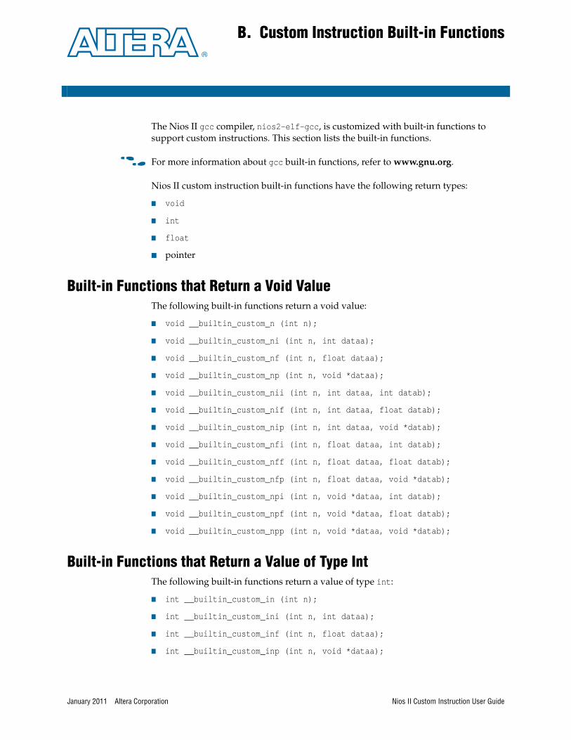
January 2011 Altera Corporation
B. Custom Instruction Built-in Functions
The Nios II gcc compiler, nios2-elf-gcc, is customized with built-in functions to support custom instructions. This section lists the built-in functions.
f For more information about gcc built-in functions, refer to www.gnu.org.
Nios II custom instruction built-in functions have the following return types:
■ void
■ int
■ float
■ pointer
Built-in Functions that Return a Void ValueThe following built-in functions return a void value:
■ void __builtin_custom_n (int n);
■ void __builtin_custom_ni (int n, int dataa);
■ void __builtin_custom_nf (int n, float dataa);
■ void __builtin_custom_np (int n, void *dataa);
■ void __builtin_custom_nii (int n, int dataa, int datab);
■ void __builtin_custom_nif (int n, int dataa, float datab);
■ void __builtin_custom_nip (int n, int dataa, void *datab);
■ void __builtin_custom_nfi (int n, float dataa, int datab);
■ void __builtin_custom_nff (int n, float dataa, float datab);
■ void __builtin_custom_nfp (int n, float dataa, void *datab);
■ void __builtin_custom_npi (int n, void *dataa, int datab);
■ void __builtin_custom_npf (int n, void *dataa, float datab);
■ void __builtin_custom_npp (int n, void *dataa, void *datab);
Built-in Functions that Return a Value of Type IntThe following built-in functions return a value of type int:
■ int __builtin_custom_in (int n);
■ int __builtin_custom_ini (int n, int dataa);
■ int __builtin_custom_inf (int n, float dataa);
■ int __builtin_custom_inp (int n, void *dataa);
Nios II Custom Instruction User Guide
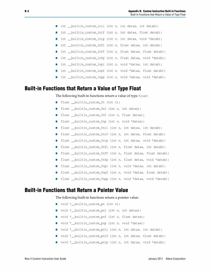
B–2 Appendix B: Custom Instruction Built-in FunctionsBuilt-in Functions that Return a Value of Type Float
■ int __builtin_custom_inii (int n, int dataa, int datab);
■ int __builtin_custom_inif (int n, int dataa, float datab);
■ int __builtin_custom_inip (int n, int dataa, void *datab);
■ int __builtin_custom_infi (int n, float dataa, int datab);
■ int __builtin_custom_inff (int n, float dataa, float datab);
■ int __builtin_custom_infp (int n, float dataa, void *datab);
■ int __builtin_custom_inpi (int n, void *dataa, int datab);
■ int __builtin_custom_inpf (int n, void *dataa, float datab);
■ int __builtin_custom_inpp (int n, void *dataa, void *datab);
Built-in Functions that Return a Value of Type FloatThe following built-in functions return a value of type float:
■ float __builtin_custom_fn (int n);
■ float __builtin_custom_fni (int n, int dataa);
■ float __builtin_custom_fnf (int n, float dataa);
■ float __builtin_custom_fnp (int n, void *dataa);
■ float __builtin_custom_fnii (int n, int dataa, int datab);
■ float __builtin_custom_fnif (int n, int dataa, float datab);
■ float __builtin_custom_fnip (int n, int dataa, void *datab);
■ float __builtin_custom_fnfi (int n, float dataa, int datab);
■ float __builtin_custom_fnff (int n, float dataa, float datab);
■ float __builtin_custom_fnfp (int n, float dataa, void *datab);
■ float __builtin_custom_fnpi (int n, void *dataa, int datab);
■ float __builtin_custom_fnpf (int n, void *dataa, float datab);
■ float __builtin_custom_fnpp (int n, void *dataa, void *datab);
Built-in Functions that Return a Pointer ValueThe following built-in functions return a pointer value:
■ void *__builtin_custom_pn (int n);
■ void *__builtin_custom_pni (int n, int dataa);
■ void *__builtin_custom_pnf (int n, float dataa);
■ void *__builtin_custom_pnp (int n, void *dataa);
■ void *__builtin_custom_pnii (int n, int dataa, int datab);
■ void *__builtin_custom_pnif (int n, int dataa, float datab);
■ void *__builtin_custom_pnip (int n, int dataa, void *datab);
Nios II Custom Instruction User Guide January 2011 Altera Corporation

Appendix B: Custom Instruction Built-in Functions B–3Built-in Functions that Return a Pointer Value
■ void *__builtin_custom_pnfi (int n, float dataa, int datab);
■ void *__builtin_custom_pnff (int n, float dataa, float datab);
■ void *__builtin_custom_pnfp (int n, float dataa, void *datab);
■ void *__builtin_custom_pnpi (int n, void *dataa, int datab);
■ void *__builtin_custom_pnpf (int n, void *dataa, float datab);
■ void *__builtin_custom_pnpp (int n, void *dataa, void *datab);
January 2011 Altera Corporation Nios II Custom Instruction User Guide

B–4 Appendix B: Custom Instruction Built-in FunctionsBuilt-in Functions that Return a Pointer Value
Nios II Custom Instruction User Guide January 2011 Altera Corporation
January 2011 Altera Corporation
C. Floating Point Custom Instructions
If you add a floating point custom instruction to your system, conflicts could arise in the software build process. This appendix describes how to handle these conflicts.
Both Qsys and SOPC Builder offer a predefined Floating Point Hardware component that you can add to your system. When you add this component to your system, a parameter editor displays, and you can turn on an option to include a floating point divider. The parameter editor notifies you that the component generates single-precision floating point hardware.
When you add the floating point custom instruction to your system and run the software build process, flags are added to your nios2-elf-gcc command line. These flags specify the opcode extensions of the custom instructions that are called by the software and select the appropriate library.
One of the following two flags appears:
■ -mcustom-fpu-cfg=60-1
■ -mcustom-fpu-cfg=60-2
The flag value 60-1 indicates your system does not include a custom instruction floating point divider, and the flag value 60-2 indicates your system includes a custom instruction floating point divider.
The -mcustom-fpu-cfg flags forces the use of single-precision constants. To allow double-precision constants, you must remove the -mcustom-fpu-cfg flag and replace it with different individual compiler flags, depending on the flag value.
To enable double-precision floating point constants, follow one of these steps:
■ Replace the command-line option string -mcustom-fpu-cfg=60-1 with the following command-line option string:
-mcustom-fmuls=252,-mcustom-fadds=253,-mcustom-fsubs=254
■ Replace the command-line option string -mcustom-fpu-cfg=60-2 with the following command-line option string:
-mcustom-fmuls=252,-mcustom-fadds=253,-mcustom-fsubs=254,-mcustom-fdivs=255
1 Change the flags only if required. Replacing the -mcustom-fpu-cfg flag disables floating point custom instruction support in your library calls, forcing the system to use the emulated or slower version of the instruction instead.
Nios II Custom Instruction User Guide

C–2 Appendix C: Floating Point Custom Instructions
Nios II Custom Instruction User Guide January 2011 Altera Corporation
January 2011 Altera Corporation
Additional Information
This chapter provides additional information about the document and Altera.
Document Revision HistoryThe following table shows the revision history for this document.
How to Contact AlteraTo locate the most up-to-date information about Altera products, refer to the following table.
Date Version Changes
January 2011 2.0
■ Updated for Quartus II software v10.1.
■ Updated for new Qsys system integration tool flow.
■ Updated with formatting changes.
May 2008 1.5
■ Add new tutorial design.
■ Describe new custom instruction import flow.
■ Minor corrections to terminology and usage.
May 2007 1.4 Add title and core version number to page footers.
May 2007 1.3
■ Describe new component editor import flow.
■ Remove tutorial design.
■ Minor corrections to terminology and usage.
December 2004 1.2 Updates for Nios II processor vresion 1.1.
September 2004 1.1 Updates for Nios II processor version 1.01.
May 2004 1.0 Initial release.
Contact (1) Contact Method Address
Technical support Website www.altera.com/support
Technical trainingWebsite www.altera.com/training
Email [email protected]
Product literature Website www.altera.com/literature
Non-technical support (General) Email [email protected]
(Software Licensing) Email [email protected]
Note to Table:
(1) You can also contact your local Altera sales office or sales representative.
Nios II Custom Instruction User Guide
Info–2 Additional InformationTypographic Conventions
Typographic ConventionsThe following table shows the typographic conventions this document uses.
Visual Cue Meaning
Bold Type with Initial Capital Letters
Indicate command names, dialog box titles, dialog box options, and other GUI labels. For example, Save As dialog box. For GUI elements, capitalization matches the GUI.
bold typeIndicates directory names, project names, disk drive names, file names, file name extensions, software utility names, and GUI labels. For example, \qdesigns directory, D: drive, and chiptrip.gdf file.
Italic Type with Initial Capital Letters Indicate document titles. For example, Stratix IV Design Guidelines.
italic typeIndicates variables. For example, n + 1.
Variable names are enclosed in angle brackets (< >). For example, <file name> and <project name>.pof file.
Initial Capital Letters Indicate keyboard keys and menu names. For example, the Delete key and the Options menu.
“Subheading Title” Quotation marks indicate references to sections within a document and titles of Quartus II Help topics. For example, “Typographic Conventions.”
Courier type
Indicates signal, port, register, bit, block, and primitive names. For example, data1, tdi, and input. The suffix n denotes an active-low signal. For example, resetn.
Indicates command line commands and anything that must be typed exactly as it appears. For example, c:\qdesigns\tutorial\chiptrip.gdf.
Also indicates sections of an actual file, such as a Report File, references to parts of files (for example, the AHDL keyword SUBDESIGN), and logic function names (for example, TRI).
r An angled arrow instructs you to press the Enter key.
1., 2., 3., anda., b., c., and so on
Numbered steps indicate a list of items when the sequence of the items is important, such as the steps listed in a procedure.
■ ■ ■ Bullets indicate a list of items when the sequence of the items is not important.
1 The hand points to information that requires special attention.
A question mark directs you to a software help system with related information.
f The feet direct you to another document or website with related information.
c A caution calls attention to a condition or possible situation that can damage or destroy the product or your work.
w A warning calls attention to a condition or possible situation that can cause you injury.
The envelope links to the Email Subscription Management Center page of the Altera website, where you can sign up to receive update notifications for Altera documents.
Nios II Custom Instruction User Guide January 2011 Altera Corporation