Embed Size (px)
Citation preview
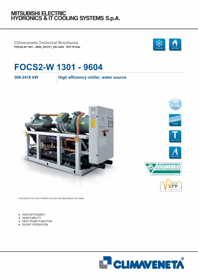
(The photo of the unit is indicative and may vary depending on the model)
HIGH EFFICIENCYADAPTABILITYHEAT PUMP FUNCTIONSILENT OPERATION
Climaveneta Technical BrochuresFOCS2-W 1301 - 9604_201211_EN rel02 HCF R134a
FOCS2-W 1301 - 9604306-2416 kW High efficiency chiller, water source
This company participates in the Eurovent Certifi cation Programme. The products are listed
in the Directory of certifi ed products. The Eurovent certifi cate, for the applicable units,
refers to products with cooling capacity up to 600 kW, voluntarily extended up to 1500 kW, for
air-cooled models and water-cooled models.
Climaveneta S.p.A.:
Quality System complying with the requirements of UNI EN ISO9001:2008 regulation
Environmental Management System complying with the requirements of UNI EN ISO14001:2004 regulation
CERTIFICATIONS
Product certifi cations
Voluntary product certifi cations
System certifi cations
II
FOCS2-W
HFC R134a
SUMMARY FOCS2-W 1301 - 9604
1. Product presentation 1.2 High efficiency
1.3 Adaptability 1.4 Silent operation 1.5 Heat pump function
2. Unit description 2.1 Standard unit composition 2.2 Certifications 2.3 Unit’s test 2.4 Electronic control W3000TE2.5 Versions 2.6 Functions 2.7 Accessories 2.8 Group regulation device MANAGER 3000 2.9 Supervisory device FWS 3000
3. Technical data 3.1 General technical data
4. Selection limits 5. Hydraulic data
5.1 Water flow and pressure drop 6. Electrical data 7. Full load sound level 8. Dimensional drawings 9. Legend of pipe connections 10.Condensation control devices 11.VPF system
pg. n° IIIpg. n° IIIpg. n° IIIpg. n° III pg. n° IIIpg. n° 1 pg. n° 1pg. n° 1pg. n° 2 pg. n° 2pg. n° 2 pg. n° 2pg. n° 3pg. n° 5pg. n° 5pg. n° 6pg. n° 6pg. n° 13pg. n° 18pg. n° 18pg. n° 22pg. n° 24pg. n° 26pg. n° 66pg. n° A1pg. n° B1
Liability disclaimerThis bulletin is not exhaustive about: installation, use, safety precautions, handling and transport. Refer to the “General Manual of Installation” for further information.This bulletin refers to standard executions, particularly as re-gards dimensions, weight, electric, hydraulic, aeraulic and re-frigerant connections (where applicable). Contact Climaveneta
Commercial Office for further drawings and schemes.
Climaveneta declines any liability deriving from use of thebulletin.This bulletin is the exclusive property of Climaveneta and all forms of copy are prohibited.The data contained herein are subject to change without no-tice.
The units highlighted in this publication contain HFC R134a [GWP100 1430] fluorinated greenhouse gases.
III
FOCS2-W
HFC R134a
Unit for indoor installation for chilled water production. Semihermetic screw compressors optimized to operate with low compression ratio and R134a; shell and tubes condenser and direct expansion evaporator; electronic expansion valve. Frame in polyester-painted galvanized steel. High eff ciency unit: the innovative optimized compressors and the high performing heat exchangers enhance EER values up to 5,1 (CA version) and even up to 5,6 (CA-E version) at Eurovent standars condi-tions.
1.2 High eff ciencyThe version ´CA-E´ is characterized by ef f ciency beyond the ´Class A´ for Eurovent. The technological choices adopted as-sure the minimization of operating costs and therefore a quick payback time.
1.3 AdaptabilityAdaptability at the building’s cooling request thanks to the con-tinuous capacity regulation, assured by sophisticated control’s logic.
1.4 Silent operationSilent operation thanks to the accurate unit’ s design. Optional integral acoustic enclosure, further reduces the sound level beyond the best on market.
1.5 Heat pump functionHeat pump function water circuit side reversal.
1. PRODUCT PRESENTATION

*********************************************************************
*****************************
********************************************* **** ******* ************* **** ******** ****** ************ **************************************************************************************** ****** **** ****** ********** **** ******* ********** ********************** ********** ******* ********* ****************** *********** *********** *********** ****** **** *********** ********** ************ **** **** ******************************************************************************************************************************************** ************************************************************************************************************************************
***********************************************************************************************************************************************************************
************************************************************************************************************************************************************************************************************************************************************************************************* *************************** ************ ********************************** *** ******** ****** *** ************* ********** ***** *********** *** **************
* ****** ***** ******************** ******** ************* ***** ***************************
* **************************************** ***************************************************** *************************************************
************************************************************************************************************************* ****** ************ ***** ** ****** **** ********* ******** ************************************************************************************** **** **** *** *********** ******* **** ********* ********* ****** ************************************************************************************* ************** **************** *** ************** ********* *************** *************** ***************** ****************** ****************** *********** ***** **** ******* ********* **** ************* ******************** ************ *********** ****** ************* ******** **************************************************************************************************************************************************************************************************************************************************** *** **** ********* ********* ******** ** ********* ******************* *********** ***** *********** **** ********** ********* *************** **** *** ***** *** **** ********** **** **** ***** ******* **** ******* *********** ***** ********* ******** *** ****** **** ********* ******** ***************** ********** **** ***** ****** ********** ***** *********** *** ********************************************************************************** ****** ************************* *************** ***************************************************************************************************************************************************************************************** ***** *** ***** *********** *** ******** **** ************ ******* *** *********************************
******************************************************************************************************** **** ****** ****** ******** *** **** ****** ********* *********** **** ****************************************************** ****** ********** ***** ** ******* ************ ********** *** **************************************************************** ***************************** ***********************************
*********************************************************************** ************* ********* ******* *** ******** *** ********* *** ******** ************************************************************************ ***** ********** *********** ***** **** **** ***** ************************ *********** **** ********** ********** **** ********** ********************************
************************************ ***** ****** **** ***** ********** **** **** ***** ********* **** ************* **** ***** ********** **** **** ******* ********* ***** *** ***** ***************************************************************************************************************************************************************************************************************************************** *** ********* **** ** ******** ************** *** ****** ***** *** **** **************************************** ******* ****** **** *********** **** *********** ******** *** ******** ************************************************************************************************************************************ ************ ***** *********** ************ ******** ***** ******************************************************************************************************************************************
****************************************** **** ******** ****** ****** *** ********** ************ ************************** ********************** **************************** *************************** ******************************************* ********************** ****************************************************** ************************************* ************************ ******************************************* ************************ *****************************
************************************************************************************************************** ******************************* **************************************************************** ******************************************************** ****** ******** ******** ******** ******** ************ **** *************************
* ************************************************************** ***************************** *********************** ********************************* **************************************************** *********************************************************** *** ****** ********** ************** *********** ********************
*************** ********** *********** **** *********** ********* *** ********** ************************* ************ *************************** ********** ****** **************************************************************************************************************************************************************** ********* ****** *** **** *********** ********** ***** *** ***** ***** **** ************** *** ********** **** *** **** ***** ********* *********** **** ******************************************************************************************************************************** ****** **** ********** *** ****** ****** ********** ********** ***********
*********************************** ****** **** ******** *********** ******* ********* ********** *************** **** ****** ******* ********* ********* ** ********* ***** *** ********************************************************************************* **** ***** ******* *** **** ******** ******* ****** ********** ************************************************************************************** *********** ******* ********** **** **** ****** ************ ***** ************* ******* *** **** ********** *** ***** *** *** **** ***** **** *** **** ******

*********************************************************************
***** **** ********** *** ********* ****** *** **** ****** ******* *********** **************** ******** ***** *********** ************** ********** ************* ****** ******* *********** ******* ********** *********** ******** *********** ********* ***** ******* *** **** ***** ***** ** ************ ******************* *** ***** *** **** ******** ******** *** **** ************ *** ******************************* ************ ********** ** ********* ****** *********** ******** ****************************************************************************************************************************************************************************************************************************************************** ********* **** ************ ************ **** ********* ******** ************************** ************** ************ *********** **************************************************************************************************************************************************************************************************** ********* *** **** ************* ****** ******* **** ********* *** ************************************************************************** ******** *** ************** *** **** *********** *********** *** **** ************** ****** *** **** *********** **** ********** *** **** ****** ******************************* ***** ********** ********* *********** **** *** *********** *******************************************************************************************************************
******************************************* ******** ****** ****************** ************** ***** ******************* ********** ******* ********** ***** *********** ***** ********************** ****** ***** **** ******* ********* *** **** **** ******* **** ** ******************************************
******************************************************************************************************************************************************************************************************** *********** **** ********* ***** *********** ********* ******************************
**********************************************************************************
************************** **** *********** *** ******** ******* ********* *** *** ********** ************** *** **** ****************** *** **** *********** *** **** ****************** **** ******** ***** *** ************** **** **** *** **** ****** ***************** ***** ********* *** ***** **** ************ ***** ********* **** ****************************************************************************
******************************************************************** ************************************************* **** **** ************* ***** ********* **** ***** ******** *************************************************************************************************************************************************************************
******************************************* ***** *********** *** ********** ****** **** ***** ***** *** ********** ************* ************ ****** *** ********** **** *** ****** ******************* *** **** **** *********** *** **** *** ******* **** ***** *** ** **********************************************************************
3
FOCS2-W
HFC R134a
ACCESSORIES DESCRIPTION BENEFIT
Soft start Electronic device adopted to manage the inrush current.Break down of the inrush current as soon as the electrical motor is switch on, lower motor's mechani-cal wear, favourable sizing for the electrical system.
Integral acoustic enclosure basicEnclosure realized with peraluman panels lined with an acoustic insu-lation made by polyester f ber of thickness 30 mm. The sound power level reduction achieved with this accessory is 14 dB(A).
Integral acoustic enclosure plus
Enclosure realized with peraluman panels lined with a special acoustic insulation composed by 5 alternating layers of polyurethane and gaiter of total thickness 50 mm. The sound power level reduction achieved with this accessory is 18 dB(A).
Pressostatic valve for the condensa-tion control (see dedicate section)
Pressostatic valve with grey cast iron body. It's used for regulating the f ow of water as a function of the condensing pressure, maintaining it constant during operation. When the refrigeration plant is stopped, the cooling water f ow is shut off automatically. The valve is selected and tested by Climaveneta during the unit's test. Recommended for applications with low temperature water, for example groundwater, where it's request the condensation pressure's control and it's possible to work with variable f ow on the rejection circuit (Separately supplied, not mounted)
CuNi condensers
Shell and tube heat exchanger recommended for applications with water with an high corrosion potential. Headers, shell, baff es and refrigerant connection in carbon steel. Available tubes in CuNi 90/10 all, or CuNi 70/30; the last option is recommended for marine water applications. [Consider a penalization on the condensation temperatu-re of 2,5°C (/CA version) and 2,0°C (/CA-E) for 90/10 alloy, and of 4°C (/CA version) or 3°C (/CA-E version) for 70/30]
0-10 V signal for the condensation's control 0-10 V signal on terminal board for the condensation control.
For dry-cooler or cooling tower applications, it permits to modulate the fans' speed in order to maintain the condensing pressure in a pre-def ned range. Max transmission lenght 30 m. Shielded cable is recommended.
VPF system (see dedicate section)
Predisposition for the variable f ow pumps' control on the primary circuit. The system comprise: extensions on the controller to read the system's pressure transducer signals (4-20 mA) and the consequent management of pumps and bypass valve (0-10 V signal), additional pressure transducer as extra safety device. [Pressure transducer, pumps and bypass valve at client responsability]
kit HWT
Kit for increased condenser leaving water temperature up to 60°C. To ensure control of the condenser leaving water temperature, this option must be f tted for /H function. NOTE: the adoption of "kit HWT" modif es the unit's performance in all the operating range; refer to the selection software to have the correct technical data.
The accessory is required for applications with high condensing temperature (heat pump, high level heat reclaim or dry cooler applications).
Partial heat reclaim management (Fig. 1)
On/off and thermal relay fot controlling the auxiliary pumps on the desuperheat circuit.
This option minimizes pumps’ consumption. They are activated only when real capability of heat reclaim is detected: compressors on, hot storage tank’s temperature lower than its set-point and than compressors’ outlet gas temperature. [Pumps at client responsability]
Compressors' ON/OFF signal Auxiliary contacts providing a voltage-free signal Allows remote signalling of compressor's activation or remote control of any auxiliary loads.
ModBUS connectivity Interface module for ModBUS protocols Allows integration with BMS operating with ModBUS protocol
BACnet connectivity Interface module for BACnet protocols Allows integration with BMS operating with BACnet protocol
Echelon connectivity Interface module for Echelon systems Allows integration with BMS operating with LonWor-ks procotls
Auxiliary Signal 4-20mA 4..20mA analogue input. Allows to change the operating set-point according to the value of current applied to the analogue input Enforce Energy Saving policies
Compressor suction valve Shut-off solenoid valve on compressor's suction circuit. Simplif es maintenance activities
Prearrangement for remote LCD display keyboard type W3000 Compact Easy of use, multi-language user interface, remote unit's control
Automatic circuit breakers Over-current switch on the major electrical loads. It protects compressors and/or fans from possible current peaks.
Input remote demand limit Digital input (voltage free) It permits to limit the unit's power absorption for safety reasons or in temporary situation.
Numbered cables on electrical board
Remote Signal Double SP Allows to activate the Energy Saving set-point Enforce Energy Saving policy
Evaporator f owswitch (water side)
Container packing
Rubber anti vibration device
2.7 Accessories

4
FOCS2-W
HFC R134a
ACCESSORIES DESCRIPTION BENEFIT
Relay for pump(s) managment Relay for the pump(s) on/off.It permits the pumps on/off. In case of 2 pumps, one in stand-by to the other, it's possible to balance the operating hours between them.
Flanged condenser connection
Power factor correction
BACnet over IP connectivity Interface module for BACnet OVER-IP protocols Allows to interconnect BACnet devices over Internet Protocol within wide-area networks
DEMETRA (see dedicated manual) Software to monitor capacity and energy absorbed by the units.Allows a dynamic monitoring of the installed units and therefore a data (hourly based) downloading to support the current needs of energy management.
Group regulation device (see dedicate section)
Supervisory device (see dedicate section)
Condensers’ collectors (Fig. 2)
Hydraulic collector between the source-side circuit and the auxiliary heat exchanger. It’s available only for FOCS2-W/CA, 3/4 compressors.
It semplif es the in-plant operations reducing to a minimum the number of connections and avoiding the water f owing under the electrical panel.
FOCS2-W/CA 3 compressors
Compressor n°1 outlet pipe
Compressor n°2 outlet pipe
Desuperheater on circuit 1
Desuperheater on circuit 2
Storage tank
Plant
T1
T3
T2
T1, T2 and T3: Thermostats supplied and cabled by Climaveneta. The correct positioning of the temperature probes inside the storage tank is at customer care.
Fig. 1 - Operating scheme of the “partial heat reclaim management” device for two circuits units
Fig. 2 - Condensers’ collectors
FOCS2-W/CA 4 compressors
ACCESSORIES
5
FOCS2-W
HFC R134a
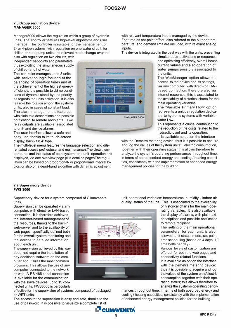
2.8 Group regulation device MANAGER 3000
Manager3000 allows the regulation within a group of hydronic units. The controller features high-level algorithms and user interface. The controller is suitable for the management of 2- or 4-pipe systems, with regulation on one water circuit, for chiller- or heat pump units and relevant mode change-over, and also with regulation on two circuits, with independent set-points and parameters, thus exploiting the simultaneous supply of chilled- and hot water. The controller manages up to 8 units, with activation logic focused at the balancing of operation times and at the achievement of the highest energy eff ciency. It is possible to def ne condi-tions of dynamic stand-by and priority as regards the units’ activation. It is also feasible the rotation among the system’s units, also in cases of constant load. The alarm management is featured, with plain text descriptions and possible notif cation to remote recipients. Two relay outputs are available, associated to unit- and device alarms. The user interface allows a safe and easy use, thanks to its touch-screen display, back-lit 8.4” type. The multi-level menu features the language selection and diffe-rentiated access prof les(user and maintenance).The circuit tem-peratures and the status of both system- and unit- operation are displayed, via one overview page plus detailed pages. The regu-lation can be based on proportional- or proportional+integral lo-gics, or also on a dead-band algorithm with dynamic adjustment,
2.9 Supervisory device FWS 3000
Supervisory device for a system composed of Climaveneta units. Supervision can be operated via any computer, with direct- or LAN-based connection. It is therefore achieved the internet-based management of the resources, thanks to the built-in web-server and to the availability of web pages specif cally def ned both for the overall system monitoring and the access to detailed information about each unit. The supervision achieved by this way does not require the installation of any additional software on the com-puter and utilizes the most common browsers. This allows the use of any computer connected to the network or web. A RS-485 serial connection is available for the communication with the slave devices, up to 15 con-nected units. FWS3000 is particularly effective for the supervision of systems composed of packaged or WET units. The access to the supervision is easy and safe, thanks to the use of password. It is possible to visualize a complete list of
with relevant temperature inputs managed by the device. Features as set-point offset, also referred to the outdoor tem-perature, and demand limit are included, with relevant analog inputs. The device is integrated in the best way with the units, preventing
simultaneous activations or resources and optimizing eff ciency, overall inrush current values and also operation of water pumps possibly associated to the units. The WebManager option allows the access to the device and its settings, via any computer, with direct- or LAN-based connection, therefore also via internet resources; this is associated to the availability of historical charts for the main operating variables. The “Variable Primary Flow” option represents a unique regulation dedica-ted to hydronic systems with variable water f ow. This represents a crucial contribution to the reduction of the costs related to the hydraulic plant and its operation.It is available as option the interface
with the Demetra metering device: thus it is possible to acquire and log the values of the system units’ electric consumption, together with their operating status; this allows therefore to analyze the system’s operating performances throughout time, in terms of both absorbed energy and cooling / heating capaci-ties, consistently with the implementation of enhanced energy management policies for the building.
unit operational variables: temperatures, humidity , indoor air quality, status of the unit. This is associated to the availability
of historical charts for the main ope-rating variables. It is also available the display of alarms, with plain text descriptions and possible notif cation to remote recipient. The setting of the main operational parameters, for each unit, is also allowed: unit status, mode, set-point, time scheduling (based on 4 days, 10 time belts per day). Various levels of customization are offered, for both the web pages and connectivity-related functions.It is available as option the interface with the Demetra metering device: thus it is possible to acquire and log the values of the system units’ electric consumption, together with their ope-rating status; this allows therefore to analyze the system’s operating perfor-
mances throughout time, in terms of both absorbed energy and cooling / heating capacities, consistently with the implementation of enhanced energy management policies for the building.

HCF R134a6/CA
FOCS2-W /CA3.1 GENERAL TECHNICAL DATA
FOCS2-W /CA 1301 1401 1601 1801 2101 2401 2701 2802 3001 3202Power supply V/ph/Hz 400/3/50 400/3/50 400/3/50 400/3/50 400/3/50 400/3/50 400/3/50 400/3/50 400/3/50 400/3/50PERFORMANCECOOLING ONLY (GROSS VALUE)Cooling capacity (1) kW 306 348 422 477 538 607 675 694 746 844Total power input (1) kW 60,5 68,7 83,4 94,4 106 120 133 137 148 167EER (1) 5,06 5,07 5,06 5,06 5,07 5,07 5,06 5,05 5,06 5,06ESEER (1) 5,94 5,95 5,73 5,84 5,94 5,92 5,79 5,94 5,91 5,87COOLING ONLY (EN14511 VALUE)Cooling capacity (1)(2) kW 305 347 420 476 536 604 673 692 743 841EER (1)(2) 4,86 4,87 4,85 4,87 4,89 4,86 4,88 4,87 4,86 4,89ESEER (1)(2) 5,45 5,45 5,25 5,41 5,50 5,42 5,38 5,44 5,43 5,41Cooling energy class B B B B B B B B B BCOOLING WITH PARTIAL RECOVERYCooling capacity (3) kW 318 361 438 495 558 630 700 720 774 876Total power input (3) kW 58,4 66,3 80,4 91,1 102 115 129 133 142 161Desuperheater heating capacity (3) kW 15,7 17,8 21,6 24,5 27,5 31,1 34,7 35,7 38,3 43,3COOLING WITH TOTAL HEAT RECOVERYCooling capacity with total heat recovery (4) kW 276 314 376 425 484 546 603 625 667 752Total power input (4) kW 76,8 87,3 104 118 133 150 166 175 183 209Recovery heat exchanger capacity (4) kW 348 396 474 536 608 687 759 790 839 948EXCHANGERSHEAT EXCHANGER USER SIDE IN REFRIGERATIONWater flow (1) m³/h 52,7 60,0 72,6 82,2 92,6 104 116 119 129 145Pressure drop (1) kPa 41,9 45,0 52,7 41,7 44,2 56,3 44,1 47,0 54,7 45,4HEAT EXCHANGER SOURCE SIDE INREFRIGERATIONWater flow (1) m³/h 62,9 71,5 86,6 98,0 110 125 139 143 153 173Pressure drop (1) kPa 35,9 35,0 34,8 34,6 34,5 36,2 34,8 34,8 36,2 34,8PARTIAL RECOVERY USER SIDE INREFRIGERATIONWater flow (3) m³/h 2,73 3,10 3,76 4,26 4,78 5,40 6,02 6,20 6,66 7,52Pressure drop (3) kPa 34,6 32,3 34,3 33,7 33,4 30,9 30,9 32,3 35,4 34,3HEAT EXCHANGER RECOVERY USER SIDE INREFRIGERATIONWater flow (4) m³/h 60,5 68,8 82,3 93,2 106 119 132 137 146 165Pressure drop (4) kPa 33,3 32,4 31,4 31,3 31,6 33,2 31,5 32,2 32,8 31,5COMPRESSORSN. of compressors N° 1 1 1 1 1 1 1 2 1 2Number of capacity N° 0 0 0 0 0 0 0 0 0 0No. of circuits N° 1 1 1 1 1 1 1 2 1 2Regulation STEPLESS STEPLESS STEPLESS STEPLESS STEPLESS STEPLESS STEPLESS STEPLESS STEPLESS STEPLESS
Min. capacity step % 25 25 25 25 25 25 25 25 25 25Refrigerant R134a R134a R134a R134a R134a R134a R134a R134a R134a R134aRefrigerant charge kg 45,0 44,0 70,0 70,0 71,0 68,0 94,0 87,0 94,0 143Oil charge kg 19,0 19,0 35,0 35,0 35,0 35,0 38,0 38,0 38,0 70,0NOISE LEVELNoise Pressure (5) dB(A) 65 65 65 65 65 65 67 67 67 67Noise Power (6) dB(A) 97 97 97 97 97 97 99 99 99 99SIZE AND WEIGHTA (7) mm 3830 3830 3860 3860 3860 3860 3930 4200 3930 4750B (7) mm 900 900 900 900 900 900 900 1150 900 1150H (7) mm 1700 1700 1840 1840 1840 1840 1990 2050 1990 2050Operating weight (7) kg 2050 2110 2590 2810 2910 2970 3510 4120 3600 5110
Notes:1 Evaporator water (in/out) = 12°C/7°C, condenser water (in/out) = 30°C/35°C, based on Eurovent Standard2 Values in compliance with EN14511-3:20113 Evaporator water (in/out): 12°C/7°C; Condenser water (in/out): 30°C/35°C; Desuperheater water (in/out): 40°C/45°C.4 Evaporator water (in/out) = 12°C/7°C; Recovery unit water (in/out) = 40°C/45°C.5 Average sound pressure level, at 10m distance, unit in a free field on a reflective surface; non-binding value obtained from the sound power level.6 Sound power on the basis of measurements made in compliance with ISO 9614 and Eurovent 8/1 for Eurovent certified units; in compliance with ISO 3744 for non-certified units.7 Unit in standard configuration/execution, without optional accessories.- Unavailable
HCF R134a7/CA
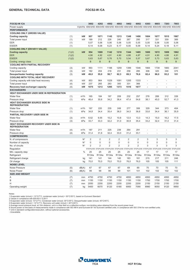
FOCS2-W /CAGENERAL TECHNICAL DATA
FOCS2-W /CA 3602 4202 4502 4802 5402 6002 6303 6603 7203 7803Power supply V/ph/Hz 400/3/50 400/3/50 400/3/50 400/3/50 400/3/50 400/3/50 400/3/50 400/3/50 400/3/50 400/3/50PERFORMANCECOOLING ONLY (GROSS VALUE)Cooling capacity (1) kW 957 1071 1145 1213 1348 1490 1604 1677 1815 1967Total power input (1) kW 189 212 226 240 267 295 317 331 359 389EER (1) 5,07 5,06 5,06 5,06 5,05 5,05 5,05 5,06 5,05 5,06ESEER (1) 6,14 6,08 6,23 6,17 6,00 6,09 6,14 6,24 6,18 6,11COOLING ONLY (EN14511 VALUE)Cooling capacity (1)(2) kW 954 1069 1142 1210 1344 1485 1600 1672 1809 1962EER (1)(2) 4,90 4,92 4,91 4,90 4,88 4,87 4,91 4,90 4,88 4,91ESEER (1)(2) 5,63 5,67 5,78 5,70 5,54 5,57 5,67 5,73 5,63 5,63Cooling energy class B B B B B B B B B BCOOLING WITH PARTIAL RECOVERYCooling capacity (3) kW 993 1111 1188 1259 1399 1546 1664 1739 1883 2041Total power input (3) kW 182 204 218 231 258 285 306 320 346 375Desuperheater heating capacity (3) kW 49,0 55,0 58,7 62,3 69,3 76,6 82,4 86,0 93,2 101COOLING WITH TOTAL HEAT RECOVERYCooling capacity with total heat recovery (4) kW 853 964 1029 1091 1205 1333 - - - -Total power input (4) kW 237 265 283 300 331 366 - - - -Recovery heat exchanger capacity (4) kW 1075 1213 1295 1373 1516 1677 - - - -EXCHANGERSHEAT EXCHANGER USER SIDE IN REFRIGERATIONWater flow (1) m³/h 165 184 197 209 232 257 276 289 312 339Pressure drop (1) kPa 46,4 30,6 34,2 38,4 47,4 54,6 38,1 45,0 52,7 41,3HEAT EXCHANGER SOURCE SIDE INREFRIGERATIONWater flow (1) m³/h 197 220 235 249 277 306 329 344 373 404Pressure drop (1) kPa 34,8 34,4 35,4 36,0 34,5 36,6 33,6 34,4 36,1 35,9PARTIAL RECOVERY USER SIDE INREFRIGERATIONWater flow (3) m³/h 8,52 9,55 10,2 10,8 12,0 13,3 14,3 15,0 16,2 17,5Pressure drop (3) kPa 33,7 33,3 32,2 31,0 30,9 35,4 33,2 32,4 31,0 31,4HEAT EXCHANGER RECOVERY USER SIDE INREFRIGERATIONWater flow (4) m³/h 187 211 225 239 264 291 - - - -Pressure drop (4) kPa 31,4 31,6 32,4 33,0 31,2 33,1 - - - -COMPRESSORSN. of compressors N° 2 2 2 2 2 2 3 3 3 3Number of capacity N° 0 0 0 0 0 0 0 0 0 0No. of circuits N° 2 2 2 2 2 2 3 3 3 3Regulation STEPLESS STEPLESS STEPLESS STEPLESS STEPLESS STEPLESS STEPLESS STEPLESS STEPLESS STEPLESS
Min. capacity step % 25 25 25 25 25 25 17 17 17 17Refrigerant R134a R134a R134a R134a R134a R134a R134a R134a R134a R134aRefrigerant charge kg 141 141 144 140 183 181 215 217 211 246Oil charge kg 70,0 70,0 70,0 70,0 76,0 76,0 105 105 105 111NOISE LEVELNoise Pressure (5) dB(A) 67 67 67 67 69 69 70 70 70 70Noise Power (6) dB(A) 99 99 99 99 101 101 102 102 102 102SIZE AND WEIGHTA (7) mm 4750 4750 4750 4750 4850 4850 4950 4950 4950 4950B (7) mm 1150 1150 1150 1150 1150 1150 1700 1700 1700 1700H (7) mm 2050 2200 2200 2200 2200 2200 2150 2150 2150 2150Operating weight (7) kg 5400 6070 6120 6180 6950 7090 8980 9050 9120 9950
Notes:1 Evaporator water (in/out) = 12°C/7°C, condenser water (in/out) = 30°C/35°C, based on Eurovent Standard2 Values in compliance with EN14511-3:20113 Evaporator water (in/out): 12°C/7°C; Condenser water (in/out): 30°C/35°C; Desuperheater water (in/out): 40°C/45°C.4 Evaporator water (in/out) = 12°C/7°C; Recovery unit water (in/out) = 40°C/45°C.5 Average sound pressure level, at 10m distance, unit in a free field on a reflective surface; non-binding value obtained from the sound power level.6 Sound power on the basis of measurements made in compliance with ISO 9614 and Eurovent 8/1 for Eurovent certified units; in compliance with ISO 3744 for non-certified units.7 Unit in standard configuration/execution, without optional accessories.- Unavailable

HCF R134a8/CA
FOCS2-W /CAGENERAL TECHNICAL DATA
FOCS2-W /CA 8103 9003 9004 9604Power supply V/ph/Hz 400/3/50 400/3/50 400/3/50 400/3/50PERFORMANCECOOLING ONLY (GROSS VALUE)Cooling capacity (1) kW 2024 2236 2278 2416Total power input (1) kW 400 442 451 478EER (1) 5,05 5,06 5,05 5,05ESEER (1) 6,09 6,14 6,23 6,17COOLING ONLY (EN14511 VALUE)Cooling capacity (1)(2) kW 2018 2228 2273 2410EER (1)(2) 4,90 4,89 4,92 4,91ESEER (1)(2) 5,61 5,60 5,80 5,71Cooling energy class B B B BCOOLING WITH PARTIAL RECOVERYCooling capacity (3) kW 2100 2319 2363 2507Total power input (3) kW 386 427 435 461Desuperheater heating capacity (3) kW 104 115 117 124COOLING WITH TOTAL HEAT RECOVERYCooling capacity with total heat recovery (4) kW - - - -Total power input (4) kW - - - -Recovery heat exchanger capacity (4) kW - - - -EXCHANGERSHEAT EXCHANGER USER SIDE IN REFRIGERATIONWater flow (1) m³/h 349 385 392 416Pressure drop (1) kPa 43,7 53,3 32,3 36,3HEAT EXCHANGER SOURCE SIDE INREFRIGERATIONWater flow (1) m³/h 416 459 468 496Pressure drop (1) kPa 34,6 35,8 35,0 37,0PARTIAL RECOVERY USER SIDE INREFRIGERATIONWater flow (3) m³/h 18,1 19,9 20,3 21,6Pressure drop (3) kPa 30,9 35,3 31,9 30,9HEAT EXCHANGER RECOVERY USER SIDE INREFRIGERATIONWater flow (4) m³/h - - - -Pressure drop (4) kPa - - - -COMPRESSORSN. of compressors N° 3 3 4 4Number of capacity N° 0 0 0 0No. of circuits N° 3 3 4 4Regulation STEPLESS STEPLESS STEPLESS STEPLESS
Min. capacity step % 17 17 12.5 12.5Refrigerant R134a R134a R134a R134aRefrigerant charge kg 289 281 287 281Oil charge kg 114 114 140 140NOISE LEVELNoise Pressure (5) dB(A) 70 70 70 70Noise Power (6) dB(A) 102 102 102 102SIZE AND WEIGHTA (7) mm 4950 4950 4650 4650B (7) mm 1700 1700 2250 2250H (7) mm 2150 2150 2230 2230Operating weight (7) kg 10170 10350 14330 14390
Notes:1 Evaporator water (in/out) = 12°C/7°C, condenser water (in/out) = 30°C/35°C, based on Eurovent Standard2 Values in compliance with EN14511-3:20113 Evaporator water (in/out): 12°C/7°C; Condenser water (in/out): 30°C/35°C; Desuperheater water (in/out): 40°C/45°C.4 Evaporator water (in/out) = 12°C/7°C; Recovery unit water (in/out) = 40°C/45°C.5 Average sound pressure level, at 10m distance, unit in a free field on a reflective surface; non-binding value obtained from the sound power level.6 Sound power on the basis of measurements made in compliance with ISO 9614 and Eurovent 8/1 for Eurovent certified units; in compliance with ISO 3744 for non-certified units.7 Unit in standard configuration/execution, without optional accessories.- Unavailable
HCF R134a9/CA/H
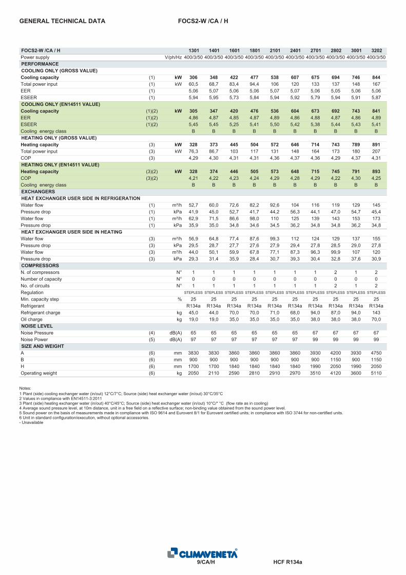
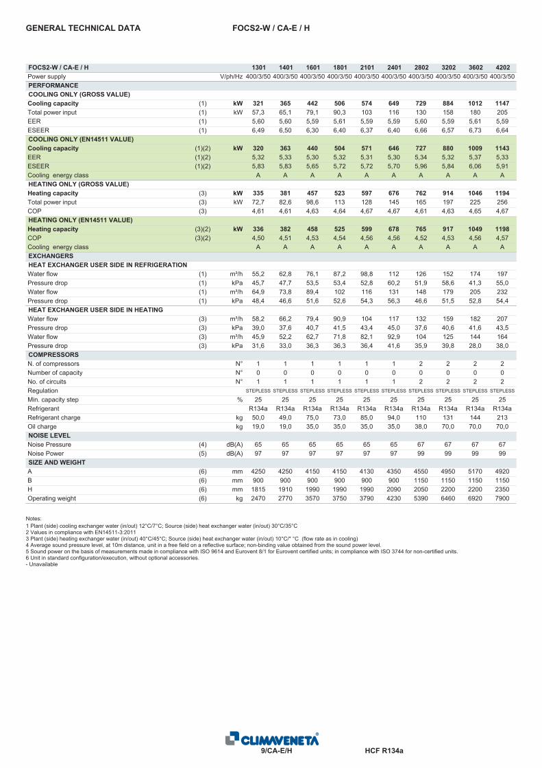
FOCS2-W /CA / HGENERAL TECHNICAL DATA
FOCS2-W /CA / H 1301 1401 1601 1801 2101 2401 2701 2802 3001 3202Power supply V/ph/Hz 400/3/50 400/3/50 400/3/50 400/3/50 400/3/50 400/3/50 400/3/50 400/3/50 400/3/50 400/3/50PERFORMANCECOOLING ONLY (GROSS VALUE)Cooling capacity (1) kW 306 348 422 477 538 607 675 694 746 844Total power input (1) kW 60,5 68,7 83,4 94,4 106 120 133 137 148 167EER (1) 5,06 5,07 5,06 5,06 5,07 5,07 5,06 5,05 5,06 5,06ESEER (1) 5,94 5,95 5,73 5,84 5,94 5,92 5,79 5,94 5,91 5,87COOLING ONLY (EN14511 VALUE)Cooling capacity (1)(2) kW 305 347 420 476 536 604 673 692 743 841EER (1)(2) 4,86 4,87 4,85 4,87 4,89 4,86 4,88 4,87 4,86 4,89ESEER (1)(2) 5,45 5,45 5,25 5,41 5,50 5,42 5,38 5,44 5,43 5,41Cooling energy class B B B B B B B B B BHEATING ONLY (GROSS VALUE)Heating capacity (3) kW 328 373 445 504 572 646 714 743 789 891Total power input (3) kW 76,3 86,7 103 117 131 148 164 173 180 207COP (3) 4,29 4,30 4,31 4,31 4,36 4,37 4,36 4,29 4,37 4,31HEATING ONLY (EN14511 VALUE)Heating capacity (3)(2) kW 328 374 446 505 573 648 715 745 791 893COP (3)(2) 4,21 4,22 4,23 4,24 4,29 4,28 4,29 4,22 4,30 4,25Cooling energy class B B B B B B B B B BEXCHANGERSHEAT EXCHANGER USER SIDE IN REFRIGERATIONWater flow (1) m³/h 52,7 60,0 72,6 82,2 92,6 104 116 119 129 145Pressure drop (1) kPa 41,9 45,0 52,7 41,7 44,2 56,3 44,1 47,0 54,7 45,4Water flow (1) m³/h 62,9 71,5 86,6 98,0 110 125 139 143 153 173Pressure drop (1) kPa 35,9 35,0 34,8 34,6 34,5 36,2 34,8 34,8 36,2 34,8HEAT EXCHANGER USER SIDE IN HEATINGWater flow (3) m³/h 56,9 64,8 77,4 87,6 99,3 112 124 129 137 155Pressure drop (3) kPa 29,5 28,7 27,7 27,6 27,9 29,4 27,8 28,5 29,0 27,8Water flow (3) m³/h 44,0 50,1 59,9 67,8 77,1 87,3 96,3 99,9 107 120Pressure drop (3) kPa 29,3 31,4 35,9 28,4 30,7 39,3 30,4 32,8 37,6 30,9COMPRESSORSN. of compressors N° 1 1 1 1 1 1 1 2 1 2Number of capacity N° 0 0 0 0 0 0 0 0 0 0No. of circuits N° 1 1 1 1 1 1 1 2 1 2Regulation STEPLESS STEPLESS STEPLESS STEPLESS STEPLESS STEPLESS STEPLESS STEPLESS STEPLESS STEPLESS
Min. capacity step % 25 25 25 25 25 25 25 25 25 25Refrigerant R134a R134a R134a R134a R134a R134a R134a R134a R134a R134aRefrigerant charge kg 45,0 44,0 70,0 70,0 71,0 68,0 94,0 87,0 94,0 143Oil charge kg 19,0 19,0 35,0 35,0 35,0 35,0 38,0 38,0 38,0 70,0NOISE LEVELNoise Pressure (4) dB(A) 65 65 65 65 65 65 67 67 67 67Noise Power (5) dB(A) 97 97 97 97 97 97 99 99 99 99SIZE AND WEIGHTA (6) mm 3830 3830 3860 3860 3860 3860 3930 4200 3930 4750B (6) mm 900 900 900 900 900 900 900 1150 900 1150H (6) mm 1700 1700 1840 1840 1840 1840 1990 2050 1990 2050Operating weight (6) kg 2050 2110 2590 2810 2910 2970 3510 4120 3600 5110
Notes:1 Plant (side) cooling exchanger water (in/out) 12°C/7°C; Source (side) heat exchanger water (in/out) 30°C/35°C2 Values in compliance with EN14511-3:20113 Plant (side) heating exchanger water (in/out) 40°C/45°C; Source (side) heat exchanger water (in/out) 10°C/* °C (flow rate as in cooling)4 Average sound pressure level, at 10m distance, unit in a free field on a reflective surface; non-binding value obtained from the sound power level.5 Sound power on the basis of measurements made in compliance with ISO 9614 and Eurovent 8/1 for Eurovent certified units; in compliance with ISO 3744 for non-certified units.6 Unit in standard configuration/execution, without optional accessories.- Unavailable

HCF R134a10/CA/H
FOCS2-W /CA / HGENERAL TECHNICAL DATA
FOCS2-W /CA / H 3602 4202 4502 4802 5402 6002 6303 6603 7203 7803Power supply V/ph/Hz 400/3/50 400/3/50 400/3/50 400/3/50 400/3/50 400/3/50 400/3/50 400/3/50 400/3/50 400/3/50PERFORMANCECOOLING ONLY (GROSS VALUE)Cooling capacity (1) kW 957 1071 1145 1213 1348 1490 1604 1677 1815 1967Total power input (1) kW 189 212 226 240 267 295 317 331 359 389EER (1) 5,07 5,06 5,06 5,06 5,05 5,05 5,05 5,06 5,05 5,06ESEER (1) 6,14 6,08 6,23 6,17 6,00 6,09 6,14 6,24 6,18 6,11COOLING ONLY (EN14511 VALUE)Cooling capacity (1)(2) kW 954 1069 1142 1210 1344 1485 1600 1672 1809 1962EER (1)(2) 4,90 4,92 4,91 4,90 4,88 4,87 4,91 4,90 4,88 4,91ESEER (1)(2) 5,63 5,67 5,78 5,70 5,54 5,57 5,67 5,73 5,63 5,63Cooling energy class B B B B B B B B B BHEATING ONLY (GROSS VALUE)Heating capacity (3) kW 1010 1141 1217 1291 1426 1577 1709 1785 1934 2082Total power input (3) kW 234 262 279 296 327 361 393 409 444 477COP (3) 4,31 4,35 4,36 4,35 4,36 4,37 4,35 4,36 4,35 4,36HEATING ONLY (EN14511 VALUE)Heating capacity (3)(2) kW 1012 1143 1220 1294 1429 1580 1712 1789 1938 2086COP (3)(2) 4,25 4,30 4,30 4,29 4,30 4,30 4,29 4,30 4,29 4,30Cooling energy class B B B B B B B B B BEXCHANGERSHEAT EXCHANGER USER SIDE IN REFRIGERATIONWater flow (1) m³/h 165 184 197 209 232 257 276 289 312 339Pressure drop (1) kPa 46,4 30,6 34,2 38,4 47,4 54,6 38,1 45,0 52,7 41,3Water flow (1) m³/h 197 220 235 249 277 306 329 344 373 404Pressure drop (1) kPa 34,8 34,4 35,4 36,0 34,5 36,6 33,6 34,4 36,1 35,9HEAT EXCHANGER USER SIDE IN HEATINGWater flow (3) m³/h 176 198 212 224 248 274 297 310 336 362Pressure drop (3) kPa 27,8 27,9 28,6 29,2 27,6 29,3 27,3 27,9 29,4 28,8Water flow (3) m³/h 136 154 164 174 192 213 230 241 261 281Pressure drop (3) kPa 31,6 21,3 23,8 26,7 32,6 37,6 26,6 31,3 36,8 28,5COMPRESSORSN. of compressors N° 2 2 2 2 2 2 3 3 3 3Number of capacity N° 0 0 0 0 0 0 0 0 0 0No. of circuits N° 2 2 2 2 2 2 3 3 3 3Regulation STEPLESS STEPLESS STEPLESS STEPLESS STEPLESS STEPLESS STEPLESS STEPLESS STEPLESS STEPLESS
Min. capacity step % 25 25 25 25 25 25 17 17 17 17Refrigerant R134a R134a R134a R134a R134a R134a R134a R134a R134a R134aRefrigerant charge kg 141 141 144 140 183 181 215 217 211 246Oil charge kg 70,0 70,0 70,0 70,0 76,0 76,0 105 105 105 111NOISE LEVELNoise Pressure (4) dB(A) 67 67 67 67 69 69 70 70 70 70Noise Power (5) dB(A) 99 99 99 99 101 101 102 102 102 102SIZE AND WEIGHTA (6) mm 4750 4750 4750 4750 4850 4850 4950 4950 4950 4950B (6) mm 1150 1150 1150 1150 1150 1150 1700 1700 1700 1700H (6) mm 2050 2200 2200 2200 2200 2200 2150 2150 2150 2150Operating weight (6) kg 5400 6070 6120 6180 6950 7090 8980 9050 9120 9950
Notes:1 Plant (side) cooling exchanger water (in/out) 12°C/7°C; Source (side) heat exchanger water (in/out) 30°C/35°C2 Values in compliance with EN14511-3:20113 Plant (side) heating exchanger water (in/out) 40°C/45°C; Source (side) heat exchanger water (in/out) 10°C/* °C (flow rate as in cooling)4 Average sound pressure level, at 10m distance, unit in a free field on a reflective surface; non-binding value obtained from the sound power level.5 Sound power on the basis of measurements made in compliance with ISO 9614 and Eurovent 8/1 for Eurovent certified units; in compliance with ISO 3744 for non-certified units.6 Unit in standard configuration/execution, without optional accessories.- Unavailable

HCF R134a11/CA/H
FOCS2-W /CA / HGENERAL TECHNICAL DATA
FOCS2-W /CA / H 8103 9003 9004 9604Power supply V/ph/Hz 400/3/50 400/3/50 400/3/50 400/3/50PERFORMANCECOOLING ONLY (GROSS VALUE)Cooling capacity (1) kW 2024 2236 2278 2416Total power input (1) kW 400 442 451 478EER (1) 5,05 5,06 5,05 5,05ESEER (1) 6,09 6,14 6,23 6,17COOLING ONLY (EN14511 VALUE)Cooling capacity (1)(2) kW 2018 2228 2273 2410EER (1)(2) 4,90 4,89 4,92 4,91ESEER (1)(2) 5,61 5,60 5,80 5,71Cooling energy class B B B BHEATING ONLY (GROSS VALUE)Heating capacity (3) kW 2140 2366 2428 2577Total power input (3) kW 490 541 557 592COP (3) 4,36 4,37 4,36 4,35HEATING ONLY (EN14511 VALUE)Heating capacity (3)(2) kW 2144 2371 2433 2582COP (3)(2) 4,30 4,31 4,31 4,30Cooling energy class B B B BEXCHANGERSHEAT EXCHANGER USER SIDE IN REFRIGERATIONWater flow (1) m³/h 349 385 392 416Pressure drop (1) kPa 43,7 53,3 32,3 36,3Water flow (1) m³/h 416 459 468 496Pressure drop (1) kPa 34,6 35,8 35,0 37,0HEAT EXCHANGER USER SIDE IN HEATINGWater flow (3) m³/h 372 411 422 448Pressure drop (3) kPa 27,7 28,7 28,5 30,1Water flow (3) m³/h 289 320 328 348Pressure drop (3) kPa 30,1 36,8 22,6 25,4COMPRESSORSN. of compressors N° 3 3 4 4Number of capacity N° 0 0 0 0No. of circuits N° 3 3 4 4Regulation STEPLESS STEPLESS STEPLESS STEPLESS
Min. capacity step % 17 17 12.5 12.5Refrigerant R134a R134a R134a R134aRefrigerant charge kg 289 281 287 281Oil charge kg 114 114 140 140NOISE LEVELNoise Pressure (4) dB(A) 70 70 70 70Noise Power (5) dB(A) 102 102 102 102SIZE AND WEIGHTA (6) mm 4950 4950 4650 4650B (6) mm 1700 1700 2250 2250H (6) mm 2150 2150 2230 2230Operating weight (6) kg 10170 10350 14330 14390
Notes:1 Plant (side) cooling exchanger water (in/out) 12°C/7°C; Source (side) heat exchanger water (in/out) 30°C/35°C2 Values in compliance with EN14511-3:20113 Plant (side) heating exchanger water (in/out) 40°C/45°C; Source (side) heat exchanger water (in/out) 10°C/* °C (flow rate as in cooling)4 Average sound pressure level, at 10m distance, unit in a free field on a reflective surface; non-binding value obtained from the sound power level.5 Sound power on the basis of measurements made in compliance with ISO 9614 and Eurovent 8/1 for Eurovent certified units; in compliance with ISO 3744 for non-certified units.6 Unit in standard configuration/execution, without optional accessories.- Unavailable
HCF R134a6/CA-E
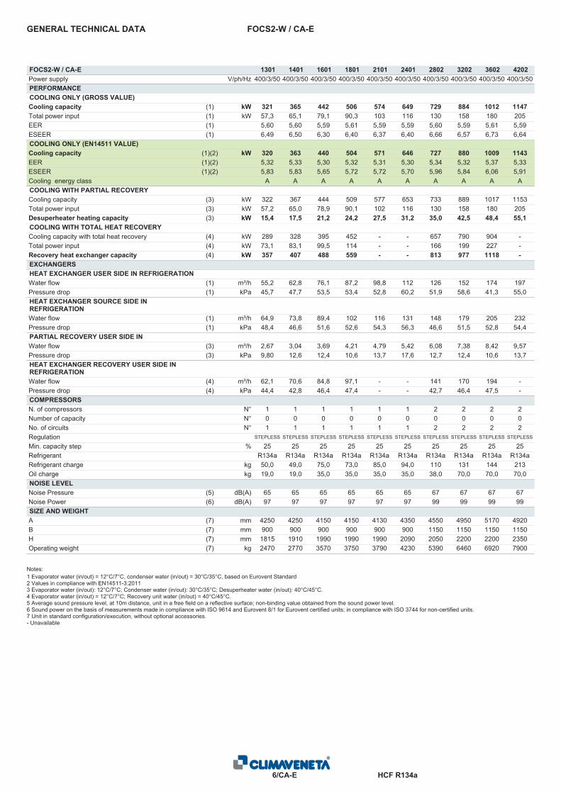
FOCS2-W / CA-EGENERAL TECHNICAL DATA
FOCS2-W / CA-E 1301 1401 1601 1801 2101 2401 2802 3202 3602 4202Power supply V/ph/Hz 400/3/50 400/3/50 400/3/50 400/3/50 400/3/50 400/3/50 400/3/50 400/3/50 400/3/50 400/3/50PERFORMANCECOOLING ONLY (GROSS VALUE)Cooling capacity (1) kW 321 365 442 506 574 649 729 884 1012 1147Total power input (1) kW 57,3 65,1 79,1 90,3 103 116 130 158 180 205EER (1) 5,60 5,60 5,59 5,61 5,59 5,59 5,60 5,59 5,61 5,59ESEER (1) 6,49 6,50 6,30 6,40 6,37 6,40 6,66 6,57 6,73 6,64COOLING ONLY (EN14511 VALUE)Cooling capacity (1)(2) kW 320 363 440 504 571 646 727 880 1009 1143EER (1)(2) 5,32 5,33 5,30 5,32 5,31 5,30 5,34 5,32 5,37 5,33ESEER (1)(2) 5,83 5,83 5,65 5,72 5,72 5,70 5,96 5,84 6,06 5,91Cooling energy class A A A A A A A A A ACOOLING WITH PARTIAL RECOVERYCooling capacity (3) kW 322 367 444 509 577 653 733 889 1017 1153Total power input (3) kW 57,2 65,0 78,9 90,1 102 116 130 158 180 205Desuperheater heating capacity (3) kW 15,4 17,5 21,2 24,2 27,5 31,2 35,0 42,5 48,4 55,1COOLING WITH TOTAL HEAT RECOVERYCooling capacity with total heat recovery (4) kW 289 328 395 452 - - 657 790 904 -Total power input (4) kW 73,1 83,1 99,5 114 - - 166 199 227 -Recovery heat exchanger capacity (4) kW 357 407 488 559 - - 813 977 1118 -EXCHANGERSHEAT EXCHANGER USER SIDE IN REFRIGERATIONWater flow (1) m³/h 55,2 62,8 76,1 87,2 98,8 112 126 152 174 197Pressure drop (1) kPa 45,7 47,7 53,5 53,4 52,8 60,2 51,9 58,6 41,3 55,0HEAT EXCHANGER SOURCE SIDE INREFRIGERATIONWater flow (1) m³/h 64,9 73,8 89,4 102 116 131 148 179 205 232Pressure drop (1) kPa 48,4 46,6 51,6 52,6 54,3 56,3 46,6 51,5 52,8 54,4PARTIAL RECOVERY USER SIDE INREFRIGERATIONWater flow (3) m³/h 2,67 3,04 3,69 4,21 4,79 5,42 6,08 7,38 8,42 9,57Pressure drop (3) kPa 9,80 12,6 12,4 10,6 13,7 17,6 12,7 12,4 10,6 13,7HEAT EXCHANGER RECOVERY USER SIDE INREFRIGERATIONWater flow (4) m³/h 62,1 70,6 84,8 97,1 - - 141 170 194 -Pressure drop (4) kPa 44,4 42,8 46,4 47,4 - - 42,7 46,4 47,5 -COMPRESSORSN. of compressors N° 1 1 1 1 1 1 2 2 2 2Number of capacity N° 0 0 0 0 0 0 0 0 0 0No. of circuits N° 1 1 1 1 1 1 2 2 2 2Regulation STEPLESS STEPLESS STEPLESS STEPLESS STEPLESS STEPLESS STEPLESS STEPLESS STEPLESS STEPLESS
Min. capacity step % 25 25 25 25 25 25 25 25 25 25Refrigerant R134a R134a R134a R134a R134a R134a R134a R134a R134a R134aRefrigerant charge kg 50,0 49,0 75,0 73,0 85,0 94,0 110 131 144 213Oil charge kg 19,0 19,0 35,0 35,0 35,0 35,0 38,0 70,0 70,0 70,0NOISE LEVELNoise Pressure (5) dB(A) 65 65 65 65 65 65 67 67 67 67Noise Power (6) dB(A) 97 97 97 97 97 97 99 99 99 99SIZE AND WEIGHTA (7) mm 4250 4250 4150 4150 4130 4350 4550 4950 5170 4920B (7) mm 900 900 900 900 900 900 1150 1150 1150 1150H (7) mm 1815 1910 1990 1990 1990 2090 2050 2200 2200 2350Operating weight (7) kg 2470 2770 3570 3750 3790 4230 5390 6460 6920 7900
Notes:1 Evaporator water (in/out) = 12°C/7°C, condenser water (in/out) = 30°C/35°C, based on Eurovent Standard2 Values in compliance with EN14511-3:20113 Evaporator water (in/out): 12°C/7°C; Condenser water (in/out): 30°C/35°C; Desuperheater water (in/out): 40°C/45°C.4 Evaporator water (in/out) = 12°C/7°C; Recovery unit water (in/out) = 40°C/45°C.5 Average sound pressure level, at 10m distance, unit in a free field on a reflective surface; non-binding value obtained from the sound power level.6 Sound power on the basis of measurements made in compliance with ISO 9614 and Eurovent 8/1 for Eurovent certified units; in compliance with ISO 3744 for non-certified units.7 Unit in standard configuration/execution, without optional accessories.- Unavailable

HCF R134a7/CA-E
FOCS2-W / CA-EGENERAL TECHNICAL DATA
FOCS2-W / CA-E 4802 2701 3001 5402 6002 6004 6404 6804 7204 7804Power supply V/ph/Hz 400/3/50 400/3/50 400/3/50 400/3/50 400/3/50 400/3/50 400/3/50 400/3/50 400/3/50 400/3/50PERFORMANCECOOLING ONLY (GROSS VALUE)Cooling capacity (1) kW 1299 707 781 1411 1551 1610 1768 1897 2025 2157Total power input (1) kW 232 128 141 256 282 289 316 338 361 386EER (1) 5,59 5,53 5,55 5,52 5,51 5,58 5,59 5,61 5,61 5,60ESEER (1) 6,66 6,38 6,41 6,66 6,55 6,65 6,57 6,72 6,75 6,64COOLING ONLY (EN14511 VALUE)Cooling capacity (1)(2) kW 1293 704 779 1407 1545 1604 1761 1891 2019 2149EER (1)(2) 5,31 5,27 5,30 5,29 5,27 5,34 5,34 5,38 5,40 5,35ESEER (1)(2) 5,87 5,76 5,81 6,00 5,88 5,98 5,89 6,08 6,13 5,94Cooling energy class A A A A A A A A A ACOOLING WITH PARTIAL RECOVERYCooling capacity (3) kW 1305 710 785 1418 1558 1618 1777 1907 2035 -Total power input (3) kW 232 128 141 255 281 288 316 338 360 -Desuperheater heating capacity (3) kW 62,4 34,3 37,9 68,6 75,7 77,5 84,9 90,9 96,9 -COOLING WITH TOTAL HEAT RECOVERYCooling capacity with total heat recovery (4) kW - - - - - - - - - -Total power input (4) kW - - - - - - - - - -Recovery heat exchanger capacity (4) kW - - - - - - - - - -EXCHANGERSHEAT EXCHANGER USER SIDE IN REFRIGERATIONWater flow (1) m³/h 224 122 135 243 267 277 304 327 349 371Pressure drop (1) kPa 65,0 51,5 47,2 46,0 55,6 56,9 58,4 45,9 41,3 59,3HEAT EXCHANGER SOURCE SIDE INREFRIGERATIONWater flow (1) m³/h 263 143 158 286 314 326 358 384 409 436Pressure drop (1) kPa 56,6 51,7 49,3 51,5 48,4 48,9 51,2 51,5 52,0 53,3PARTIAL RECOVERY USER SIDE INREFRIGERATIONWater flow (3) m³/h 10,8 5,96 6,58 11,9 13,1 13,5 14,8 15,8 16,8 -Pressure drop (3) kPa 17,6 18,2 21,5 18,2 21,5 12,5 12,4 11,4 10,6 -HEAT EXCHANGER RECOVERY USER SIDE INREFRIGERATIONWater flow (4) m³/h - - - - - - - - - -Pressure drop (4) kPa - - - - - - - - - -COMPRESSORSN. of compressors N° 2 1 1 2 2 4 4 4 4 4Number of capacity N° 0 0 0 0 0 0 0 0 0 0No. of circuits N° 2 1 1 2 2 4 4 4 4 4Regulation STEPLESS STEPLESS STEPLESS STEPLESS STEPLESS STEPLESS STEPLESS STEPLESS STEPLESS STEPLESS
Min. capacity step % 25 25 25 25 25 25 25 25 25 25Refrigerant R134a R134a R134a R134a R134a R134a R134a R134a R134a R134aRefrigerant charge kg 207 138 137 279 266 328 328 325 327 335Oil charge kg 70,0 38,0 38,0 76,0 76,0 108 140 140 140 140NOISE LEVELNoise Pressure (5) dB(A) 67 67 67 69 69 70 70 70 70 70Noise Power (6) dB(A) 99 99 99 101 101 102 102 102 102 102SIZE AND WEIGHTA (7) mm 4920 4350 4350 5200 5200 4900 4900 5220 5220 4900B (7) mm 1285 900 900 1285 1285 2250 2250 2250 2250 2250H (7) mm 2430 2180 2180 2440 2440 2305 2305 2305 2305 2455Operating weight (7) kg 8560 4760 4870 8850 8960 12200 13140 13710 13720 15850
Notes:1 Evaporator water (in/out) = 12°C/7°C, condenser water (in/out) = 30°C/35°C, based on Eurovent Standard2 Values in compliance with EN14511-3:20113 Evaporator water (in/out): 12°C/7°C; Condenser water (in/out): 30°C/35°C; Desuperheater water (in/out): 40°C/45°C.4 Evaporator water (in/out) = 12°C/7°C; Recovery unit water (in/out) = 40°C/45°C.5 Average sound pressure level, at 10m distance, unit in a free field on a reflective surface; non-binding value obtained from the sound power level.6 Sound power on the basis of measurements made in compliance with ISO 9614 and Eurovent 8/1 for Eurovent certified units; in compliance with ISO 3744 for non-certified units.7 Unit in standard configuration/execution, without optional accessories.- Unavailable
HCF R134a8/CA-E
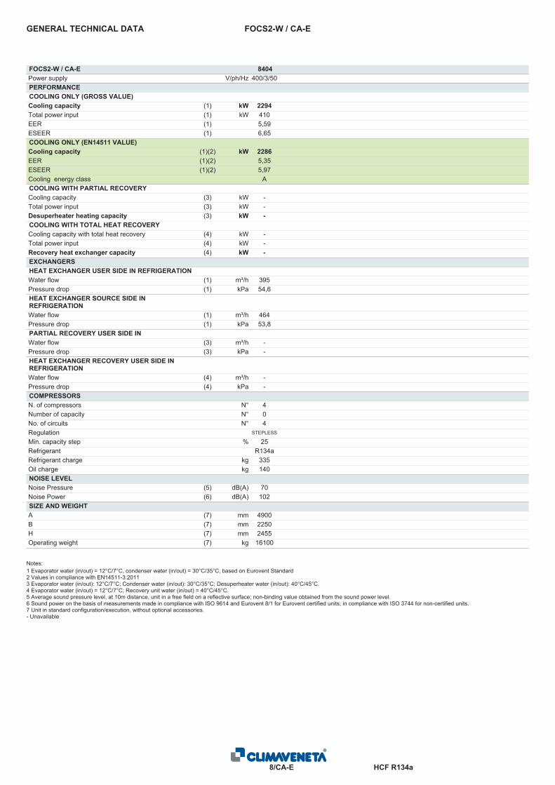
FOCS2-W / CA-EGENERAL TECHNICAL DATA
FOCS2-W / CA-E 8404Power supply V/ph/Hz 400/3/50PERFORMANCECOOLING ONLY (GROSS VALUE)Cooling capacity (1) kW 2294Total power input (1) kW 410EER (1) 5,59ESEER (1) 6,65COOLING ONLY (EN14511 VALUE)Cooling capacity (1)(2) kW 2286EER (1)(2) 5,35ESEER (1)(2) 5,97Cooling energy class ACOOLING WITH PARTIAL RECOVERYCooling capacity (3) kW -Total power input (3) kW -Desuperheater heating capacity (3) kW -COOLING WITH TOTAL HEAT RECOVERYCooling capacity with total heat recovery (4) kW -Total power input (4) kW -Recovery heat exchanger capacity (4) kW -EXCHANGERSHEAT EXCHANGER USER SIDE IN REFRIGERATIONWater flow (1) m³/h 395Pressure drop (1) kPa 54,6HEAT EXCHANGER SOURCE SIDE INREFRIGERATIONWater flow (1) m³/h 464Pressure drop (1) kPa 53,8PARTIAL RECOVERY USER SIDE INREFRIGERATIONWater flow (3) m³/h -Pressure drop (3) kPa -HEAT EXCHANGER RECOVERY USER SIDE INREFRIGERATIONWater flow (4) m³/h -Pressure drop (4) kPa -COMPRESSORSN. of compressors N° 4Number of capacity N° 0No. of circuits N° 4Regulation STEPLESS
Min. capacity step % 25Refrigerant R134aRefrigerant charge kg 335Oil charge kg 140NOISE LEVELNoise Pressure (5) dB(A) 70Noise Power (6) dB(A) 102SIZE AND WEIGHTA (7) mm 4900B (7) mm 2250H (7) mm 2455Operating weight (7) kg 16100
Notes:1 Evaporator water (in/out) = 12°C/7°C, condenser water (in/out) = 30°C/35°C, based on Eurovent Standard2 Values in compliance with EN14511-3:20113 Evaporator water (in/out): 12°C/7°C; Condenser water (in/out): 30°C/35°C; Desuperheater water (in/out): 40°C/45°C.4 Evaporator water (in/out) = 12°C/7°C; Recovery unit water (in/out) = 40°C/45°C.5 Average sound pressure level, at 10m distance, unit in a free field on a reflective surface; non-binding value obtained from the sound power level.6 Sound power on the basis of measurements made in compliance with ISO 9614 and Eurovent 8/1 for Eurovent certified units; in compliance with ISO 3744 for non-certified units.7 Unit in standard configuration/execution, without optional accessories.- Unavailable
HCF R134a9/CA-E/H
FOCS2-W / CA-E / HGENERAL TECHNICAL DATA
FOCS2-W / CA-E / H 1301 1401 1601 1801 2101 2401 2802 3202 3602 4202Power supply V/ph/Hz 400/3/50 400/3/50 400/3/50 400/3/50 400/3/50 400/3/50 400/3/50 400/3/50 400/3/50 400/3/50PERFORMANCECOOLING ONLY (GROSS VALUE)Cooling capacity (1) kW 321 365 442 506 574 649 729 884 1012 1147Total power input (1) kW 57,3 65,1 79,1 90,3 103 116 130 158 180 205EER (1) 5,60 5,60 5,59 5,61 5,59 5,59 5,60 5,59 5,61 5,59ESEER (1) 6,49 6,50 6,30 6,40 6,37 6,40 6,66 6,57 6,73 6,64COOLING ONLY (EN14511 VALUE)Cooling capacity (1)(2) kW 320 363 440 504 571 646 727 880 1009 1143EER (1)(2) 5,32 5,33 5,30 5,32 5,31 5,30 5,34 5,32 5,37 5,33ESEER (1)(2) 5,83 5,83 5,65 5,72 5,72 5,70 5,96 5,84 6,06 5,91Cooling energy class A A A A A A A A A AHEATING ONLY (GROSS VALUE)Heating capacity (3) kW 335 381 457 523 597 676 762 914 1046 1194Total power input (3) kW 72,7 82,6 98,6 113 128 145 165 197 225 256COP (3) 4,61 4,61 4,63 4,64 4,67 4,67 4,61 4,63 4,65 4,67HEATING ONLY (EN14511 VALUE)Heating capacity (3)(2) kW 336 382 458 525 599 678 765 917 1049 1198COP (3)(2) 4,50 4,51 4,53 4,54 4,56 4,56 4,52 4,53 4,56 4,57Cooling energy class A A A A A A A A A AEXCHANGERSHEAT EXCHANGER USER SIDE IN REFRIGERATIONWater flow (1) m³/h 55,2 62,8 76,1 87,2 98,8 112 126 152 174 197Pressure drop (1) kPa 45,7 47,7 53,5 53,4 52,8 60,2 51,9 58,6 41,3 55,0Water flow (1) m³/h 64,9 73,8 89,4 102 116 131 148 179 205 232Pressure drop (1) kPa 48,4 46,6 51,6 52,6 54,3 56,3 46,6 51,5 52,8 54,4HEAT EXCHANGER USER SIDE IN HEATINGWater flow (3) m³/h 58,2 66,2 79,4 90,9 104 117 132 159 182 207Pressure drop (3) kPa 39,0 37,6 40,7 41,5 43,4 45,0 37,6 40,6 41,6 43,5Water flow (3) m³/h 45,9 52,2 62,7 71,8 82,1 92,9 104 125 144 164Pressure drop (3) kPa 31,6 33,0 36,3 36,3 36,4 41,6 35,9 39,8 28,0 38,0COMPRESSORSN. of compressors N° 1 1 1 1 1 1 2 2 2 2Number of capacity N° 0 0 0 0 0 0 0 0 0 0No. of circuits N° 1 1 1 1 1 1 2 2 2 2Regulation STEPLESS STEPLESS STEPLESS STEPLESS STEPLESS STEPLESS STEPLESS STEPLESS STEPLESS STEPLESS
Min. capacity step % 25 25 25 25 25 25 25 25 25 25Refrigerant R134a R134a R134a R134a R134a R134a R134a R134a R134a R134aRefrigerant charge kg 50,0 49,0 75,0 73,0 85,0 94,0 110 131 144 213Oil charge kg 19,0 19,0 35,0 35,0 35,0 35,0 38,0 70,0 70,0 70,0NOISE LEVELNoise Pressure (4) dB(A) 65 65 65 65 65 65 67 67 67 67Noise Power (5) dB(A) 97 97 97 97 97 97 99 99 99 99SIZE AND WEIGHTA (6) mm 4250 4250 4150 4150 4130 4350 4550 4950 5170 4920B (6) mm 900 900 900 900 900 900 1150 1150 1150 1150H (6) mm 1815 1910 1990 1990 1990 2090 2050 2200 2200 2350Operating weight (6) kg 2470 2770 3570 3750 3790 4230 5390 6460 6920 7900
Notes:1 Plant (side) cooling exchanger water (in/out) 12°C/7°C; Source (side) heat exchanger water (in/out) 30°C/35°C2 Values in compliance with EN14511-3:20113 Plant (side) heating exchanger water (in/out) 40°C/45°C; Source (side) heat exchanger water (in/out) 10°C/* °C (flow rate as in cooling)4 Average sound pressure level, at 10m distance, unit in a free field on a reflective surface; non-binding value obtained from the sound power level.5 Sound power on the basis of measurements made in compliance with ISO 9614 and Eurovent 8/1 for Eurovent certified units; in compliance with ISO 3744 for non-certified units.6 Unit in standard configuration/execution, without optional accessories.- Unavailable

HCF R134a10/CA-E/H
FOCS2-W / CA-E / HGENERAL TECHNICAL DATA
FOCS2-W / CA-E / H 4802 2701 3001 5402 6002 6004 6404 6804 7204 7804Power supply V/ph/Hz 400/3/50 400/3/50 400/3/50 400/3/50 400/3/50 400/3/50 400/3/50 400/3/50 400/3/50 400/3/50PERFORMANCECOOLING ONLY (GROSS VALUE)Cooling capacity (1) kW 1299 707 781 1411 1551 1610 1768 1897 2025 2157Total power input (1) kW 232 128 141 256 282 289 316 338 361 386EER (1) 5,59 5,53 5,55 5,52 5,51 5,58 5,59 5,61 5,61 5,60ESEER (1) 6,66 6,38 6,41 6,66 6,55 6,65 6,57 6,72 6,75 6,64COOLING ONLY (EN14511 VALUE)Cooling capacity (1)(2) kW 1293 704 779 1407 1545 1604 1761 1891 2019 2149EER (1)(2) 5,31 5,27 5,30 5,29 5,27 5,34 5,34 5,38 5,40 5,35ESEER (1)(2) 5,87 5,76 5,81 6,00 5,88 5,98 5,89 6,08 6,13 5,94Cooling energy class A A A A A A A A A AHEATING ONLY (GROSS VALUE)Heating capacity (3) kW 1352 731 808 1460 1607 1674 1828 1961 2092 2238Total power input (3) kW 289 158 174 316 348 363 394 422 450 481COP (3) 4,67 4,63 4,64 4,62 4,62 4,62 4,63 4,64 4,65 4,66HEATING ONLY (EN14511 VALUE)Heating capacity (3)(2) kW 1356 733 810 1464 1611 1678 1833 1966 2098 2244COP (3)(2) 4,57 4,53 4,55 4,54 4,53 4,53 4,54 4,56 4,57 4,56Cooling energy class A A A A A A A A A AEXCHANGERSHEAT EXCHANGER USER SIDE IN REFRIGERATIONWater flow (1) m³/h 224 122 135 243 267 277 304 327 349 371Pressure drop (1) kPa 65,0 51,5 47,2 46,0 55,6 56,9 58,4 45,9 41,3 59,3Water flow (1) m³/h 263 143 158 286 314 326 358 384 409 436Pressure drop (1) kPa 56,6 51,7 49,3 51,5 48,4 48,9 51,2 51,5 52,0 53,3HEAT EXCHANGER USER SIDE IN HEATINGWater flow (3) m³/h 235 127 140 254 279 291 318 341 364 389Pressure drop (3) kPa 45,2 40,6 38,8 40,5 38,2 38,9 40,4 40,6 41,0 42,4Water flow (3) m³/h 186 100 111 200 220 229 251 269 287 307Pressure drop (3) kPa 44,9 34,9 32,1 31,2 37,8 38,9 39,6 31,1 28,0 40,6COMPRESSORSN. of compressors N° 2 1 1 2 2 4 4 4 4 4Number of capacity N° 0 0 0 0 0 0 0 0 0 0No. of circuits N° 2 1 1 2 2 4 4 4 4 4Regulation STEPLESS STEPLESS STEPLESS STEPLESS STEPLESS STEPLESS STEPLESS STEPLESS STEPLESS STEPLESS
Min. capacity step % 25 25 25 25 25 25 25 25 25 25Refrigerant R134a R134a R134a R134a R134a R134a R134a R134a R134a R134aRefrigerant charge kg 207 138 137 279 266 328 328 325 327 335Oil charge kg 70,0 38,0 38,0 76,0 76,0 108 140 140 140 140NOISE LEVELNoise Pressure (4) dB(A) 67 67 67 69 69 70 70 70 70 70Noise Power (5) dB(A) 99 99 99 101 101 102 102 102 102 102SIZE AND WEIGHTA (6) mm 4920 4350 4350 5200 5200 4900 4900 5220 5220 4900B (6) mm 1285 900 900 1285 1285 2250 2250 2250 2250 2250H (6) mm 2430 2180 2180 2440 2440 2305 2305 2305 2305 2455Operating weight (6) kg 8560 4760 4870 8850 8960 12200 13140 13710 13720 15850
Notes:1 Plant (side) cooling exchanger water (in/out) 12°C/7°C; Source (side) heat exchanger water (in/out) 30°C/35°C2 Values in compliance with EN14511-3:20113 Plant (side) heating exchanger water (in/out) 40°C/45°C; Source (side) heat exchanger water (in/out) 10°C/* °C (flow rate as in cooling)4 Average sound pressure level, at 10m distance, unit in a free field on a reflective surface; non-binding value obtained from the sound power level.5 Sound power on the basis of measurements made in compliance with ISO 9614 and Eurovent 8/1 for Eurovent certified units; in compliance with ISO 3744 for non-certified units.6 Unit in standard configuration/execution, without optional accessories.- Unavailable
HCF R134a11/CA-E/H
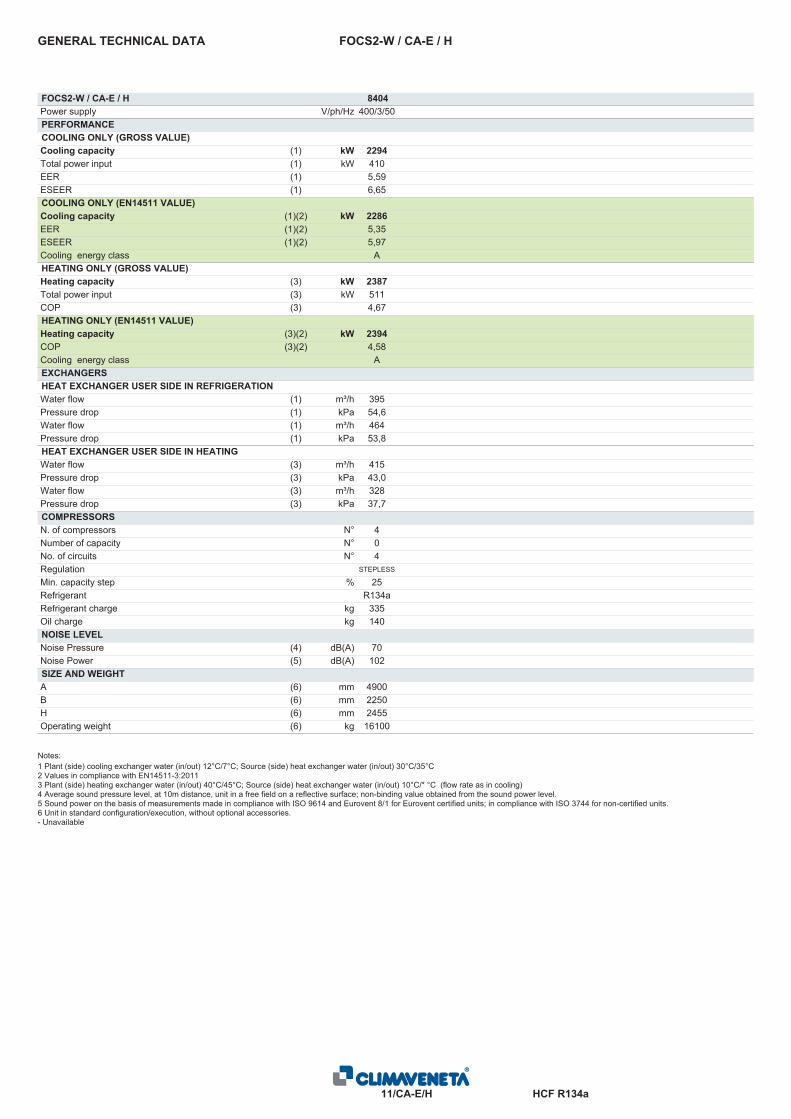
FOCS2-W / CA-E / HGENERAL TECHNICAL DATA
FOCS2-W / CA-E / H 8404Power supply V/ph/Hz 400/3/50PERFORMANCECOOLING ONLY (GROSS VALUE)Cooling capacity (1) kW 2294Total power input (1) kW 410EER (1) 5,59ESEER (1) 6,65COOLING ONLY (EN14511 VALUE)Cooling capacity (1)(2) kW 2286EER (1)(2) 5,35ESEER (1)(2) 5,97Cooling energy class AHEATING ONLY (GROSS VALUE)Heating capacity (3) kW 2387Total power input (3) kW 511COP (3) 4,67HEATING ONLY (EN14511 VALUE)Heating capacity (3)(2) kW 2394COP (3)(2) 4,58Cooling energy class AEXCHANGERSHEAT EXCHANGER USER SIDE IN REFRIGERATIONWater flow (1) m³/h 395Pressure drop (1) kPa 54,6Water flow (1) m³/h 464Pressure drop (1) kPa 53,8HEAT EXCHANGER USER SIDE IN HEATINGWater flow (3) m³/h 415Pressure drop (3) kPa 43,0Water flow (3) m³/h 328Pressure drop (3) kPa 37,7COMPRESSORSN. of compressors N° 4Number of capacity N° 0No. of circuits N° 4Regulation STEPLESS
Min. capacity step % 25Refrigerant R134aRefrigerant charge kg 335Oil charge kg 140NOISE LEVELNoise Pressure (4) dB(A) 70Noise Power (5) dB(A) 102SIZE AND WEIGHTA (6) mm 4900B (6) mm 2250H (6) mm 2455Operating weight (6) kg 16100
Notes:1 Plant (side) cooling exchanger water (in/out) 12°C/7°C; Source (side) heat exchanger water (in/out) 30°C/35°C2 Values in compliance with EN14511-3:20113 Plant (side) heating exchanger water (in/out) 40°C/45°C; Source (side) heat exchanger water (in/out) 10°C/* °C (flow rate as in cooling)4 Average sound pressure level, at 10m distance, unit in a free field on a reflective surface; non-binding value obtained from the sound power level.5 Sound power on the basis of measurements made in compliance with ISO 9614 and Eurovent 8/1 for Eurovent certified units; in compliance with ISO 3744 for non-certified units.6 Unit in standard configuration/execution, without optional accessories.- Unavailable
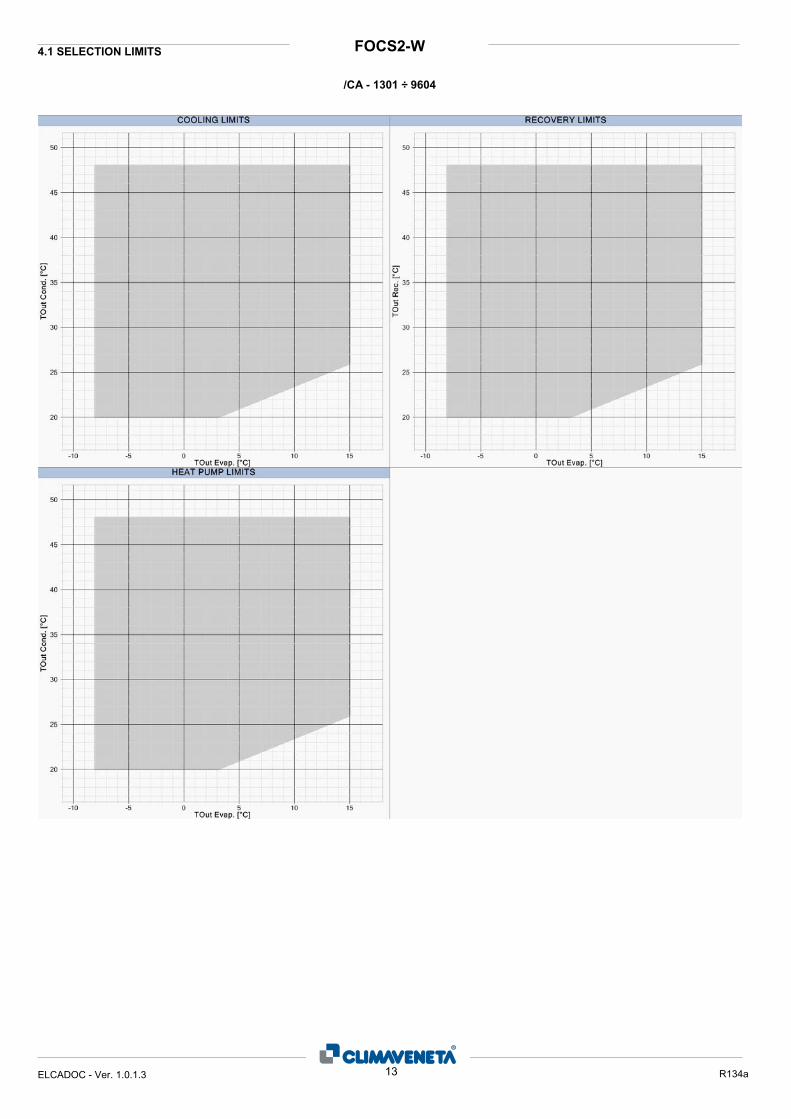
FOCS2-W4.1 SELECTION LIMITS
/CA - 1301 ÷ 9604
13ELCADOC - Ver. 1.0.1.3 R134a

FOCS2-WSELECTION LIMITS
/CA-E - 1301 ÷ 4802
14ELCADOC - Ver. 1.0.1.3 R134a
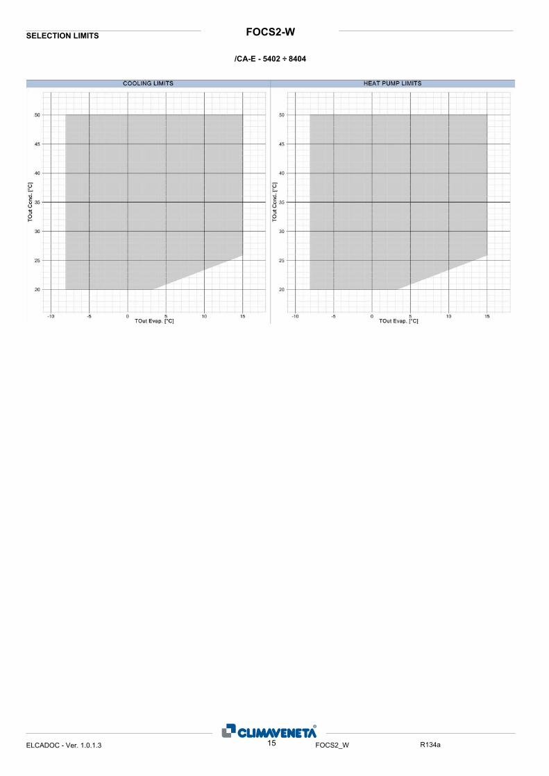
FOCS2-WSELECTION LIMITS
/CA-E - 5402 ÷ 8404
15ELCADOC - Ver. 1.0.1.3 FOCS2_W R134a
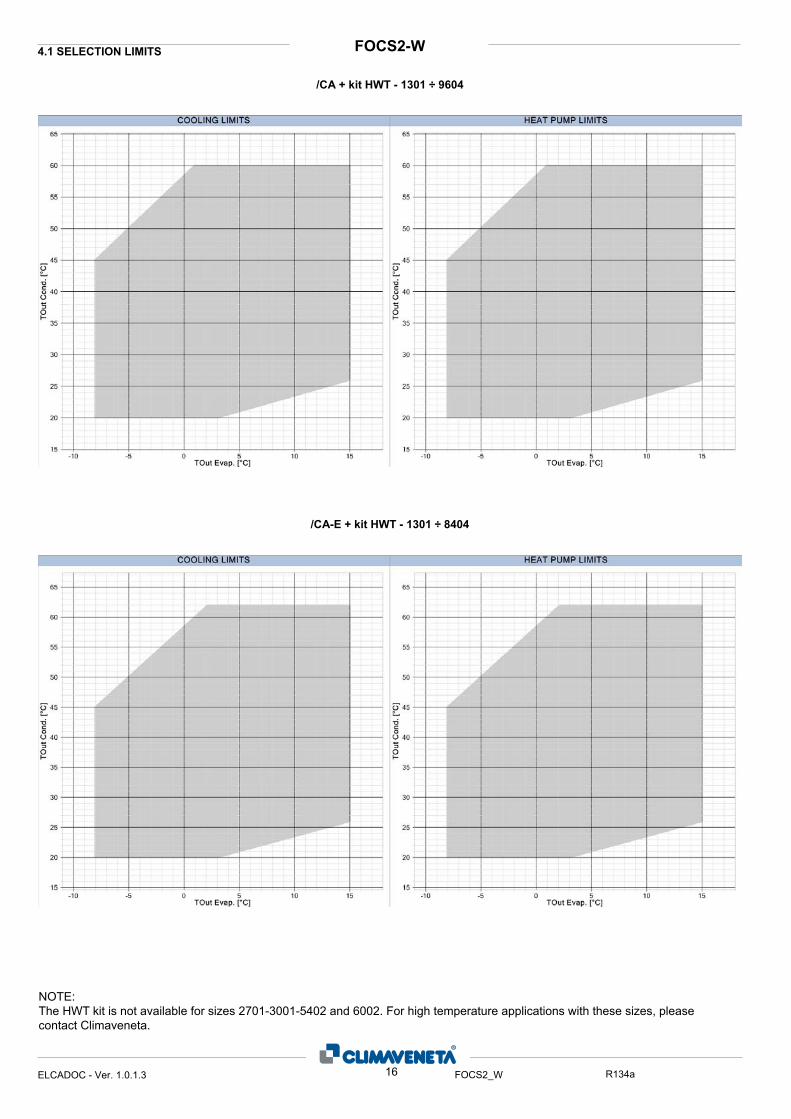
FOCS2-W4.1 SELECTION LIMITS
/CA + kit HWT - 1301 ÷ 9604
/CA-E + kit HWT - 1301 ÷ 8404
16ELCADOC - Ver. 1.0.1.3 FOCS2_W R134a
NOTE:The HWT kit is not available for sizes 2701-3001-5402 and 6002. For high temperature applications with these sizes, please contact Climaveneta.
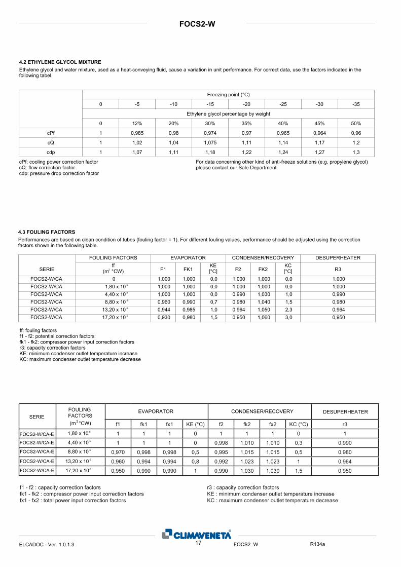
4.3 FOULING FACTORSPerformances are based on clean condition of tubes (fouling factor = 1). For different fouling values, performance should be adjusted using the correction factors shown in the following table.
FOULING FACTORS EVAPORATOR CONDENSER/RECOVERY DESUPERHEATERKE[°C] R3
KC[°C]FK2F2FK1F1SERIE
ff(m °CW)2
0,0 000,1 000,1 W/CA-2SCOF 1,000 1,000 0,0 1,0000 0,0 000,1 000,1 W/CA-2SCOF 1,000 1,000 0,0 1,0001,80 x 10-5
0,0 000,1 000,1 W/CA-2SCOF 0,990 1,030 1,0 0,9904,40 x 10-5
7,0 099,0 069,0 W/CA-2SCOF 0,980 1,040 1,5 0,9808,80 x 10-5
0,1 589,0 449,0 W/CA-2SCOF 0,964 1,050 2,3 0,96413,20 x 10-5
5,1 089,0 039,0 W/CA-2SCOF 0,950 1,060 3,0 0,95017,20 x 10-5
ff: fouling factorsf1 - f2: potential correction factorsfk1 - fk2: compressor power input correction factorsr3: capacity correction factorsKE: minimum condenser outlet temperature increaseKC: maximum condenser outlet temperature decrease
17ELCADOC - Ver. 1.0.1.3 FOCS2_W R134a
FOCS2-W
4.2 ETHYLENE GLYCOL MIXTUREEthylene glycol and water mixture, used as a heat-conveying fluid, cause a variation in unit performance. For correct data, use the factors indicated in the following tabel.
0 -5 -10 -15 -20 -25 -30 -35
50%45%40%35%30%20%12%0
0,960,9640,9650,970,9740,980,9851
1,21,171,141,111,0751,041,021
1,31,271,241,221,181,111,071cdp
cQ
cPf
cdp: pressure drop correction factorcQ: flow correction factor
)locylg enelyporp ,g,e( snoitulos ezeerf-itna fo dnik rehto gninrecnoc atad roFrotcaf noitcerroc rewop gnilooc :fPcplease contact our Sale Department.
Freezing point (°C)
Ethylene glycol percentage by weight
(m °CW) f1 fk1 fx1 KE (°C) f2 fk2 fx2 KC (°C) r3
1 1 1 0 1 1 1 0 1
1 1 1 0 0,998 1,010 1,010 0,3 0,990
0,970 0,998 0,998 0,5 0,995 1,015 1,015 0,5 0,980
0,960 0,994 0,994 0,8 0,992 1,023 1,023 1 0,964
0,950 0,990 0,990 1 0,990 1,030 1,030 1,5 0,950
2
1,80 x 10⁻⁵
4,40 x 10⁻⁵
8,80 x 10⁻⁵
13,20 x 10⁻⁵
17,20 x 10⁻⁵
SERIE
FOCS2-W/CA-E
FOCS2-W/CA-E
FOCS2-W/CA-E
FOCS2-W/CA-E
FOCS2-W/CA-E
f1 - f2 : capacity correction factorsfk1 - fk2 : compressor power input correction factorsfx1 - fx2 : total power input correction factors
r3 : capacity correction factorsKE : minimum condenser outlet temperature increase KC : maximum condenser outlet temperature decrease
DESUPERHEATERCONDENSER/RECOVERYEVAPORATORFOULING FACTORS
FOCS2-WCA/CA-E
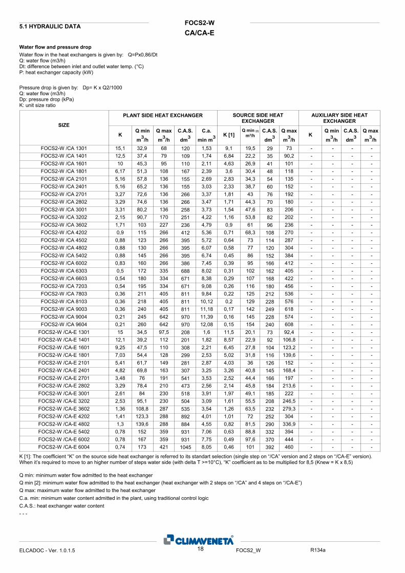
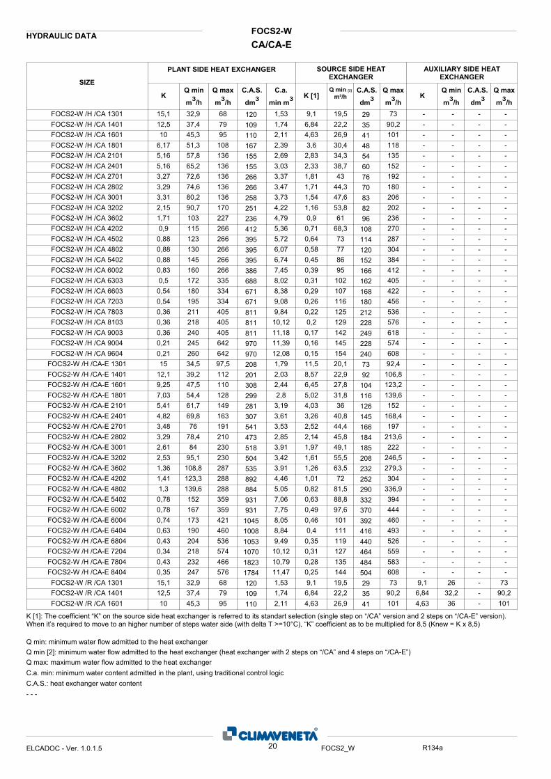
5.1 HYDRAULIC DATA
Water flow and pressure dropWater flow in the heat exchangers is given by: Q=Px0,86/Dt Q: water flow (m3/h) Dt: difference between inlet and outlet water temp. (°C) P: heat exchanger capacity (kW)
Pressure drop is given by: Dp= K x Q2/1000Q: water flow (m3/h)Dp: pressure drop (kPa)K: unit size ratio
AUXILIARY SIDE HEAT EXCHANGER
Q max
m³/h
Q min
m³/hK
SOURCE SIDE HEAT EXCHANGER
Q max
m³/h
SIZE
PLANT SIDE HEAT EXCHANGER
C.a.
min m³Q max
m³/h
Q min
m³/hK
C.A.S.
dm³C.A.S.
dm³C.A.S.
dm³K [1]Q min [2]
m³/h
15,1 32,9 68 1,53 9,1 19,5 73 - - -FOCS2-W /CA 1301 -12,5 37,4 79 1,74 6,84 22,2 90,2 - - -FOCS2-W /CA 1401 -10 45,3 95 2,11 4,63 26,9 101 - - -FOCS2-W /CA 1601 -
6,17 51,3 108 2,39 3,6 30,4 118 - - -FOCS2-W /CA 1801 -5,16 57,8 136 2,69 2,83 34,3 135 - - -FOCS2-W /CA 2101 -5,16 65,2 136 3,03 2,33 38,7 152 - - -FOCS2-W /CA 2401 -3,27 72,6 136 3,37 1,81 43 192 - - -FOCS2-W /CA 2701 -3,29 74,6 136 3,47 1,71 44,3 180 - - -FOCS2-W /CA 2802 -3,31 80,2 136 3,73 1,54 47,6 206 - - -FOCS2-W /CA 3001 -2,15 90,7 170 4,22 1,16 53,8 202 - - -FOCS2-W /CA 3202 -1,71 103 227 4,79 0,9 61 236 - - -FOCS2-W /CA 3602 -0,9 115 266 5,36 0,71 68,3 270 - - -FOCS2-W /CA 4202 -
0,88 123 266 5,72 0,64 73 287 - - -FOCS2-W /CA 4502 -0,88 130 266 6,07 0,58 77 304 - - -FOCS2-W /CA 4802 -0,88 145 266 6,74 0,45 86 384 - - -FOCS2-W /CA 5402 -0,83 160 266 7,45 0,39 95 412 - - -FOCS2-W /CA 6002 -0,5 172 335 8,02 0,31 102 405 - - -FOCS2-W /CA 6303 -
0,54 180 334 8,38 0,29 107 422 - - -FOCS2-W /CA 6603 -0,54 195 334 9,08 0,26 116 456 - - -FOCS2-W /CA 7203 -0,36 211 405 9,84 0,22 125 536 - - -FOCS2-W /CA 7803 -0,36 218 405 10,12 0,2 129 576 - - -FOCS2-W /CA 8103 -0,36 240 405 11,18 0,17 142 618 - - -FOCS2-W /CA 9003 -0,21 245 642 11,39 0,16 145 574 - - -FOCS2-W /CA 9004 -0,21 260 642 12,08 0,15 154 608 - - -FOCS2-W /CA 9604 -15 34,5 97,5 1,6 11,5 20,1 92,4 - - -FOCS2-W /CA-E 1301 -
12,1 39,2 112 1,82 8,57 22,9 106,8 - - -FOCS2-W /CA-E 1401 -9,25 47,5 110 2,21 6,45 27,8 123,2 - - -FOCS2-W /CA-E 1601 -7,03 54,4 128 2,53 5,02 31,8 139,6 - - -FOCS2-W /CA-E 1801 -5,41 61,7 149 2,87 4,03 36 152 - - -FOCS2-W /CA-E 2101 -4,82 69,8 163 3,25 3,26 40,8 168,4 - - -FOCS2-W /CA-E 2401 -3,48 76 191 3,53 2,52 44,4 197 - - -FOCS2-W /CA-E 2701 -3,29 78,4 210 2,56 2,14 45,8 213,6 - - -FOCS2-W /CA-E 2802 -2,61 84 230 3,91 1,97 49,1 222 - - -FOCS2-W /CA-E 3001 -2,53 95,1 230 3,09 1,61 55,5 246,5 - - -FOCS2-W /CA-E 3202 -1,36 108,8 287 3,54 1,26 63,5 279,3 - - -FOCS2-W /CA-E 3602 -1,41 123,3 288 4,01 1,01 72 304 - - -FOCS2-W /CA-E 4202 -1,3 139,6 288 4,55 0,82 81,5 336,9 - - -FOCS2-W /CA-E 4802 -
0,78 152 359 7,06 0,63 88,8 394 - - -FOCS2-W /CA-E 5402 -0,78 167 359 7,75 0,49 97,6 444 - - -FOCS2-W /CA-E 6002 -0,74 173 421 8,05 0,46 101 460 - - -FOCS2-W /CA-E 6004 -
K [1]: The coefficient “K” on the source side heat exchanger is referred to its standart selection (single step on “/CA” version and 2 steps on “/CA-E” version). When it’s required to move to an higher number of steps water side (with delta T >=10°C), “K” coefficient as to be multiplied for 8,5 (Knew = K x 8,5)
Q min: minimum water flow admitted to the heat exchangerQ min [2]: minimum water flow admitted to the heat exchanger (heat exchanger with 2 steps on “/CA” and 4 steps on “/CA-E”)Q max: maximum water flow admitted to the heat exchangerC.a. min: minimum water content admitted in the plant, using traditional control logicC.A.S.: heat exchanger water content- - -
18ELCADOC - Ver. 1.0.1.5 FOCS2_W R134a
120 29 109 35 110 41 167 48 155 54 155 60 266 76 266 70 258 83 251 82 236 96 412 108 395 114 395 120 395 152 386 166 688 162 671 168 671 180 811 212 811 228 811 249 970 228 970 240 208 73 201 92 308 104 299 116 281 126 307 145 541 166 473 184 518 185 504 208 535 232 892 252 884 290 931 332 931 370 1045 392
FOCS2-WCA/CA-E
HYDRAULIC DATA
AUXILIARY SIDE HEAT EXCHANGER
Q max
m³/h
Q min
m³/hK
SOURCE SIDE HEAT EXCHANGER
Q max
m³/h
SIZE
PLANT SIDE HEAT EXCHANGER
C.a.
min m³Q max
m³/h
Q min
m³/hK
C.A.S.
dm³C.A.S.
dm³C.A.S.
dm³K [1]Q min [2]
m³/h
0,63 190 460 8,84 0,4 111 493 - - -FOCS2-W /CA-E 6404 -0,43 204 536 9,49 0,35 119 526 - - -FOCS2-W /CA-E 6804 -0,34 218 574 10,12 0,31 127 559 - - -FOCS2-W /CA-E 7204 -0,43 232 466 10,79 0,28 135 583 - - -FOCS2-W /CA-E 7804 -0,35 247 576 11,47 0,25 144 608 - - -FOCS2-W /CA-E 8404 -15,1 32,9 68 1,53 9,1 19,5 73 4650 - 3,1FOCS2-W /D /CA 1301 -12,5 37,4 79 1,74 6,84 22,2 90,2 3356 - 3,5FOCS2-W /D /CA 1401 -10 45,3 95 2,11 4,63 26,9 101 2422 - 4,3FOCS2-W /D /CA 1601 -
6,17 51,3 108 2,39 3,6 30,4 118 1860 - 4,9FOCS2-W /D /CA 1801 -5,16 57,8 136 2,69 2,83 34,3 135 1460 - 5,5FOCS2-W /D /CA 2101 -5,16 65,2 136 3,03 2,33 38,7 152 1060 - 6,2FOCS2-W /D /CA 2401 -3,27 72,6 136 3,37 1,81 43 192 852 - 7FOCS2-W /D /CA 2701 -3,29 74,6 136 3,47 1,71 44,3 180 839 - 7FOCS2-W /D /CA 2802 -3,31 80,2 136 3,73 1,54 47,6 206 798 - 7,4FOCS2-W /D /CA 3001 -2,15 90,7 170 4,22 1,16 53,8 202 606 - 8,6FOCS2-W /D /CA 3202 -1,71 103 227 4,79 0,9 61 236 465 - 9,8FOCS2-W /D /CA 3602 -0,9 115 266 5,36 0,71 68,3 270 365 - 11FOCS2-W /D /CA 4202 -
0,88 123 266 5,72 0,64 73 287 309 - 11,7FOCS2-W /D /CA 4502 -0,88 130 266 6,07 0,58 77 304 265 - 12,4FOCS2-W /D /CA 4802 -0,88 145 266 6,74 0,45 86 384 213 - 14FOCS2-W /D /CA 5402 -0,83 160 266 7,45 0,39 95 412 200 - 14,8FOCS2-W /D /CA 6002 -0,5 172 335 8,02 0,31 102 405 162 - 16,5FOCS2-W /D /CA 6303 -
0,54 180 334 8,38 0,29 107 422 145 - 17,2FOCS2-W /D /CA 6603 -0,54 195 334 9,08 0,26 116 456 118 - 18,6FOCS2-W /D /CA 7203 -0,36 211 405 9,84 0,22 125 536 102 - 20,2FOCS2-W /D /CA 7803 -0,36 218 405 10,12 0,2 129 576 94,7 - 21FOCS2-W /D /CA 8103 -0,36 240 405 11,18 0,17 142 618 88,7 - 22,2FOCS2-W /D /CA 9003 -0,21 245 642 11,39 0,16 145 574 77 - 23,4FOCS2-W /D /CA 9004 -0,21 260 642 12,08 0,15 154 608 66,3 - 24,8FOCS2-W /D /CA 9604 -15 34,5 97,5 1,6 11,5 20,1 92,4 1370 - 8,2FOCS2-W /D /CA-E 1301 208 73 16
12,1 39,2 112 1,82 8,57 22,9 106,8 1370 - 8,2FOCS2-W /D /CA-E 1401 201 92 69,25 47,5 110 2,21 6,45 27,8 123,2 910 - 10,3FOCS2-W /D /CA-E 1601 308 104 97,03 54,4 128 2,53 5,02 31,8 139,6 600 - 12,3FOCS2-W /D /CA-E 1801 299 116 105,41 61,7 149 2,87 4,03 36 152 600 - 12,3FOCS2-W /D /CA-E 2101 281 126 164,82 69,8 163 3,25 3,26 40,8 168,4 600 - 12,3FOCS2-W /D /CA-E 2401 307 145 93,48 76 191 3,53 2,52 44,4 197 512 - 14FOCS2-W /D /CA-E 2701 541 166 93,29 78,4 210 2,56 2,14 45,8 213,6 343 - 16,4FOCS2-W /D /CA-E 2802 210 184 122,61 84 230 3,91 1,97 49,1 222 497 - 14FOCS2-W /D /CA-E 3001 518 185 92,53 95,1 230 3,09 1,61 55,5 246,5 228 - 20,5FOCS2-W /D /CA-E 3202 230 208 181,36 108,8 287 3,54 1,26 63,5 279,3 150 - 24,6FOCS2-W /D /CA-E 3602 287 232 201,41 123,3 288 4,01 1,01 72 304 150 - 24,6FOCS2-W /D /CA-E 4202 288 252 321,3 139,6 288 4,55 0,82 81,5 336,9 150 - 24,6FOCS2-W /D /CA-E 4802 288 290 18
0,78 152 359 7,06 0,63 88,8 394 128 - 28FOCS2-W /D /CA-E 5402 931 332 180,78 167 359 7,75 0,49 97,6 444 124,3 - 28FOCS2-W /D /CA-E 6002 931 370 180,74 173 421 8,05 0,46 101 460 69,1 - 37FOCS2-W /D /CA-E 6004 1045 392 300,63 190 460 8,84 0,4 111 493 56,9 - 41,1FOCS2-W /D /CA-E 6404 1008 416 360,43 204 536 9,49 0,35 119 526 45,7 - 45,2FOCS2-W /D /CA-E 6804 1053 440 380,34 218 574 10,12 0,31 127 559 37,5 - 49,3FOCS2-W /D /CA-E 7204 1070 464 40
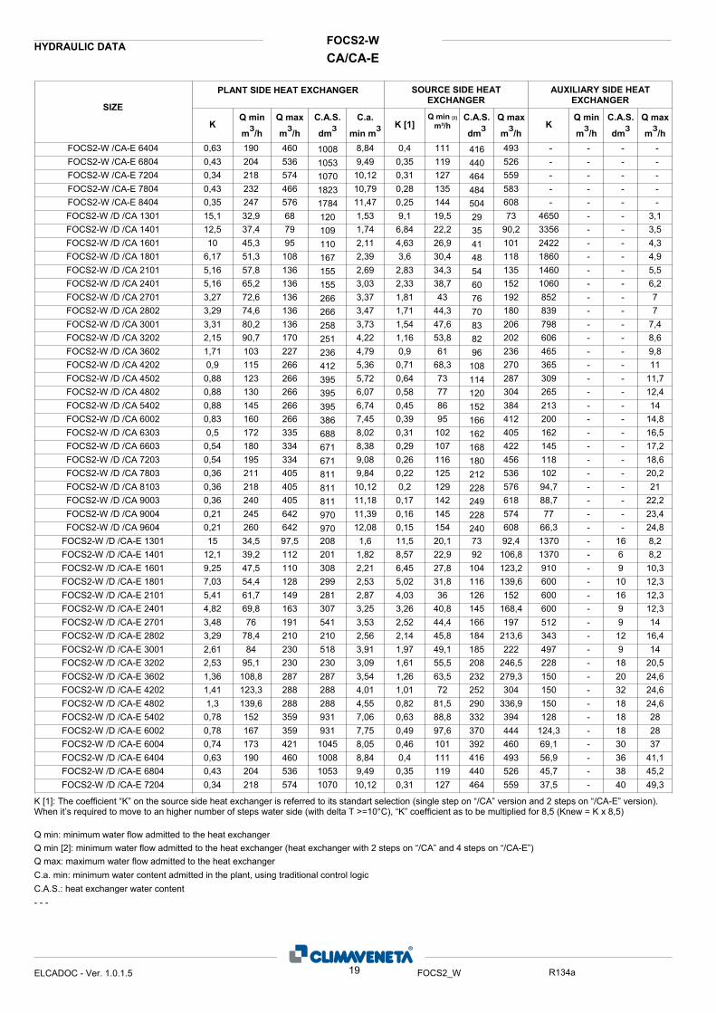
K [1]: The coefficient “K” on the source side heat exchanger is referred to its standart selection (single step on “/CA” version and 2 steps on “/CA-E” version). When it’s required to move to an higher number of steps water side (with delta T >=10°C), “K” coefficient as to be multiplied for 8,5 (Knew = K x 8,5)
Q min: minimum water flow admitted to the heat exchangerQ min [2]: minimum water flow admitted to the heat exchanger (heat exchanger with 2 steps on “/CA” and 4 steps on “/CA-E”)Q max: maximum water flow admitted to the heat exchangerC.a. min: minimum water content admitted in the plant, using traditional control logicC.A.S.: heat exchanger water content- - -
19ELCADOC - Ver. 1.0.1.5 FOCS2_W R134a
1008 416 1053 440 1070 464 1823 484 1784 504 120 29 109 35 110 41 167 48 155 54 155 60 266 76 266 70 258 83 251 82 236 96 412 108 395 114 395 120 395 152 386 166 688 162 671 168 671 180 811 212 811 228 811 249 970 228 970 240
FOCS2-WCA/CA-E
HYDRAULIC DATA
AUXILIARY SIDE HEAT EXCHANGER
Q max
m³/h
Q min
m³/hK
SOURCE SIDE HEAT EXCHANGER
Q max
m³/h
SIZE
PLANT SIDE HEAT EXCHANGER
C.a.
min m³Q max
m³/h
Q min
m³/hK
C.A.S.
dm³C.A.S.
dm³C.A.S.
dm³K [1]Q min [2]
m³/h
15,1 32,9 68 1,53 9,1 19,5 73 - - -FOCS2-W /H /CA 1301 -12,5 37,4 79 1,74 6,84 22,2 90,2 - - -FOCS2-W /H /CA 1401 -10 45,3 95 2,11 4,63 26,9 101 - - -FOCS2-W /H /CA 1601 -
6,17 51,3 108 2,39 3,6 30,4 118 - - -FOCS2-W /H /CA 1801 -5,16 57,8 136 2,69 2,83 34,3 135 - - -FOCS2-W /H /CA 2101 -5,16 65,2 136 3,03 2,33 38,7 152 - - -FOCS2-W /H /CA 2401 -3,27 72,6 136 3,37 1,81 43 192 - - -FOCS2-W /H /CA 2701 -3,29 74,6 136 3,47 1,71 44,3 180 - - -FOCS2-W /H /CA 2802 -3,31 80,2 136 3,73 1,54 47,6 206 - - -FOCS2-W /H /CA 3001 -2,15 90,7 170 4,22 1,16 53,8 202 - - -FOCS2-W /H /CA 3202 -1,71 103 227 4,79 0,9 61 236 - - -FOCS2-W /H /CA 3602 -0,9 115 266 5,36 0,71 68,3 270 - - -FOCS2-W /H /CA 4202 -
0,88 123 266 5,72 0,64 73 287 - - -FOCS2-W /H /CA 4502 -0,88 130 266 6,07 0,58 77 304 - - -FOCS2-W /H /CA 4802 -0,88 145 266 6,74 0,45 86 384 - - -FOCS2-W /H /CA 5402 -0,83 160 266 7,45 0,39 95 412 - - -FOCS2-W /H /CA 6002 -0,5 172 335 8,02 0,31 102 405 - - -FOCS2-W /H /CA 6303 -
0,54 180 334 8,38 0,29 107 422 - - -FOCS2-W /H /CA 6603 -0,54 195 334 9,08 0,26 116 456 - - -FOCS2-W /H /CA 7203 -0,36 211 405 9,84 0,22 125 536 - - -FOCS2-W /H /CA 7803 -0,36 218 405 10,12 0,2 129 576 - - -FOCS2-W /H /CA 8103 -0,36 240 405 11,18 0,17 142 618 - - -FOCS2-W /H /CA 9003 -0,21 245 642 11,39 0,16 145 574 - - -FOCS2-W /H /CA 9004 -0,21 260 642 12,08 0,15 154 608 - - -FOCS2-W /H /CA 9604 -15 34,5 97,5 1,79 11,5 20,1 92,4 - - -FOCS2-W /H /CA-E 1301 -
12,1 39,2 112 2,03 8,57 22,9 106,8 - - -FOCS2-W /H /CA-E 1401 -9,25 47,5 110 2,44 6,45 27,8 123,2 - - -FOCS2-W /H /CA-E 1601 -7,03 54,4 128 2,8 5,02 31,8 139,6 - - -FOCS2-W /H /CA-E 1801 -5,41 61,7 149 3,19 4,03 36 152 - - -FOCS2-W /H /CA-E 2101 -4,82 69,8 163 3,61 3,26 40,8 168,4 - - -FOCS2-W /H /CA-E 2401 -3,48 76 191 3,53 2,52 44,4 197 - - -FOCS2-W /H /CA-E 2701 -3,29 78,4 210 2,85 2,14 45,8 213,6 - - -FOCS2-W /H /CA-E 2802 -2,61 84 230 3,91 1,97 49,1 222 - - -FOCS2-W /H /CA-E 3001 -2,53 95,1 230 3,42 1,61 55,5 246,5 - - -FOCS2-W /H /CA-E 3202 -1,36 108,8 287 3,91 1,26 63,5 279,3 - - -FOCS2-W /H /CA-E 3602 -1,41 123,3 288 4,46 1,01 72 304 - - -FOCS2-W /H /CA-E 4202 -1,3 139,6 288 5,05 0,82 81,5 336,9 - - -FOCS2-W /H /CA-E 4802 -
0,78 152 359 7,06 0,63 88,8 394 - - -FOCS2-W /H /CA-E 5402 -0,78 167 359 7,75 0,49 97,6 444 - - -FOCS2-W /H /CA-E 6002 -0,74 173 421 8,05 0,46 101 460 - - -FOCS2-W /H /CA-E 6004 -0,63 190 460 8,84 0,4 111 493 - - -FOCS2-W /H /CA-E 6404 -0,43 204 536 9,49 0,35 119 526 - - -FOCS2-W /H /CA-E 6804 -0,34 218 574 10,12 0,31 127 559 - - -FOCS2-W /H /CA-E 7204 -0,43 232 466 10,79 0,28 135 583 - - -FOCS2-W /H /CA-E 7804 -0,35 247 576 11,47 0,25 144 608 - - -FOCS2-W /H /CA-E 8404 -15,1 32,9 68 1,53 9,1 19,5 73 9,1 26 73FOCS2-W /R /CA 1301 -12,5 37,4 79 1,74 6,84 22,2 90,2 6,84 32,2 90,2FOCS2-W /R /CA 1401 -10 45,3 95 2,11 4,63 26,9 101 4,63 36 101FOCS2-W /R /CA 1601 -
K [1]: The coefficient “K” on the source side heat exchanger is referred to its standart selection (single step on “/CA” version and 2 steps on “/CA-E” version). When it’s required to move to an higher number of steps water side (with delta T >=10°C), “K” coefficient as to be multiplied for 8,5 (Knew = K x 8,5)
Q min: minimum water flow admitted to the heat exchangerQ min [2]: minimum water flow admitted to the heat exchanger (heat exchanger with 2 steps on “/CA” and 4 steps on “/CA-E”)Q max: maximum water flow admitted to the heat exchangerC.a. min: minimum water content admitted in the plant, using traditional control logicC.A.S.: heat exchanger water content- - -
20ELCADOC - Ver. 1.0.1.5 FOCS2_W R134a
120 29 109 35 110 41 167 48 155 54 155 60 266 76 266 70 258 83 251 82 236 96 412 108 395 114 395 120 395 152 386 166 688 162 671 168 671 180 811 212 811 228 811 249 970 228 970 240 208 73 201 92 308 104 299 116 281 126 307 145 541 166 473 184 518 185 504 208 535 232 892 252 884 290 931 332 931 370 1045 392 1008 416 1053 440 1070 464 1823 484 1784 504 120 29 109 35 110 41

FOCS2-WCA/CA-E
HYDRAULIC DATA
AUXILIARY SIDE HEAT EXCHANGER
Q max
m³/h
Q min
m³/hK
SOURCE SIDE HEAT EXCHANGER
Q max
m³/h
SIZE
PLANT SIDE HEAT EXCHANGER
C.a.
min m³Q max
m³/h
Q min
m³/hK
C.A.S.
dm³C.A.S.
dm³C.A.S.
dm³K [1]Q min [2]
m³/h
6,17 51,3 108 2,39 3,6 30,4 118 3,6 42 118FOCS2-W /R /CA 1801 -5,16 57,8 136 2,69 2,83 34,3 135 2,83 48 135FOCS2-W /R /CA 2101 -5,16 65,2 136 3,03 2,33 38,7 152 2,33 54 152FOCS2-W /R /CA 2401 -3,27 72,6 136 3,37 1,81 43 192 1,81 48 192FOCS2-W /R /CA 2701 -3,29 74,6 136 3,47 1,71 44,3 180 1,71 64,4 180FOCS2-W /R /CA 2802 -3,31 80,2 136 3,73 1,54 47,6 206 1,54 54 206FOCS2-W /R /CA 3001 -2,15 90,7 170 4,22 1,16 53,8 202 1,16 72 202FOCS2-W /R /CA 3202 -1,71 103 227 4,79 0,9 61 236 0,9 84 236FOCS2-W /R /CA 3602 -0,9 115 266 5,36 0,71 68,3 270 0,71 96 270FOCS2-W /R /CA 4202 -
0,88 123 266 5,72 0,64 73 287 0,64 102 287FOCS2-W /R /CA 4502 -0,88 130 266 6,07 0,58 77,3 304 0,58 108 304FOCS2-W /R /CA 4802 -0,88 145 266 6,74 0,45 86 384 0,45 96 384FOCS2-W /R /CA 5402 -0,83 160 266 7,45 0,39 95 412 0,39 108 412FOCS2-W /R /CA 6002 -15 34,5 97,5 1,6 11,5 20,1 92,4 11,5 40,2 92,4FOCS2-W /R /CA-E 1301
12,1 39,2 112 1,82 8,57 22,9 107 8,57 45,8 107FOCS2-W /R /CA-E 14019,25 47,5 110 2,21 6,45 27,8 123 6,45 55,6 123FOCS2-W /R /CA-E 16017,03 54,4 128 2,53 5,02 31,8 140 5,02 63,6 140FOCS2-W /R /CA-E 18013,29 78,4 210 2,56 2,14 45,8 214 2,14 91,6 214FOCS2-W /R /CA-E 28022,53 95,1 230 3,09 1,61 55,5 247 1,61 111 247FOCS2-W /R /CA-E 32021,36 109 287 3,54 1,26 63,5 279 1,26 127 279FOCS2-W /R /CA-E 3602
K [1]: The coefficient “K” on the source side heat exchanger is referred to its standart selection (single step on “/CA” version and 2 steps on “/CA-E” version). When it’s required to move to an higher number of steps water side (with delta T >=10°C), “K” coefficient as to be multiplied for 8,5 (Knew = K x 8,5)
Q min: minimum water flow admitted to the heat exchangerQ min [2]: minimum water flow admitted to the heat exchanger (heat exchanger with 2 steps on “/CA” and 4 steps on “/CA-E”)Q max: maximum water flow admitted to the heat exchangerC.a. min: minimum water content admitted in the plant, using traditional control logicC.A.S.: heat exchanger water content- - -
21ELCADOC - Ver. 1.0.1.5 FOCS2_W R134a
167 48 155 54 155 60 266 76 266 70 258 83 251 82 236 96 412 108 395 114 395 120 395 152 386 166 208 73 78 201 92 89 308 104 101 299 116 110 473 184 178 504 208 202 535 232 220

CAFOCS2-W
Maximum values
6.1 ELECTRICAL DATA
SIZE
n
Compressor L.R.A.
[A] F.L.A.
[A] F.L.I. [kW]
Total (1) F.L.I.
[kW] F.L.A.
[A] S.A.
[A] 1301 1 1x89 1x146,8 1x300 89.0 147 300
1401 1 1x101,3 1x168 1x360 101 168 360
1601 1 1x121,6 1x197,2 1x318 122 197 318
1801 1 1x137,7 1x223 1x436 138 223 436
2101 1 1x154,9 1x247 1x465 155 247 465
2401 1 1x175,1 1x286 1x586 175 286 586
2701 1 1x195,5 1x318 1x650 196 318 650
2802 2 2x101,3 2x168 2x360 203 336 462
3001 1 1x216 1x351 1x805 216 351 805
3202 2 2x121,6 2x197,2 2x318 243 394 444
3602 2 2x137,7 2x223 2x436 275 446 571
4202 2 2x154,9 2x247 2x465 310 494 612
4502 2 1x154,9 + 1x175,1 1x247 + 1x286 1x465 + 1x586 330 533 733
4802 2 2x175,1 2x286 2x586 350 572 761
5402 2 2x195,5 2x318 2x650 391 636 860
6002 2 2x216 2x351 2x805 432 702 1025
6303 3 3x154,9 3x247 3x465 465 741 760
6603 3 2x154,9 + 1x175,1 2x247 + 1x286 2x465 + 1x586 485 780 881
7203 3 3x175,1 3x286 3x586 525 858 936
7803 3 1x175,1 + 2x195,5 1x286 + 2x318 1x586 + 2x650 566 922 1035
8103 3 3x195,5 3x318 3x650 587 954 1070
9003 3 3x216 3x351 3x805 648 1053 1245
9004 4 2x154,9 + 2x175,1 2x247 + 2x286 2x465 + 2x586 660 1066 1055
9604 4 4x175,1 4x286 4x586 700 1144 1111
F.L.I.: Full load power F.L.A.: Full load current L.R.A.: Locked rotor amperes for single compressor S.A.: Inrush current (1) Safety values to be considered when cabling the unit for power supply and line-protections
Power supply: 400/3/50 Voltage tolerance: 10% Maximum voltage unbalance: 3% Given the typical operating conditions of units designed for indoor installation, which can be associated (according to reference document IEC 60721) to the following classes: - climatic conditions class AA4: air temperature range from 5 up to 42°C (*) - special climatic conditions negligible - presence of water class AD2: possibility of water dripping inside the technical room - biological conditions class 4B1 and 4C2: negligible presence of corrosive and polluting substances - mechanically active substances class 4S2: locations in areas with sand or dust sources The required protection level for safe operation, according to reference document IEC 60529, is IP21 BW (protection against access of external devices with diameter larger than 12 mm and water falling vertically). The unit can be considered IP21 CW protected, thus fulfilling the above operating conditions. (*) for the unit’s operating limits, see “selection limits” section
22ELCADOC - Ver. 1.0.1.3 R134a

CA-EFOCS2-W
Maximum values
ELECTRICAL DATA
SIZE
n
Compressor L.R.A.
[A] F.L.A.
[A] F.L.I. [kW]
Total (1) F.L.I.
[kW] F.L.A.
[A] S.A.
[A] 1301 1 1x89 1x146.8 1x300 89.0 146.8 300.0
1401 1 1x101.3 1x168 1x360 101.3 168.0 360.0
1601 1 1x121.6 1x197.2 1x404 121.6 197.2 404.0
1801 1 1x137.7 1x223 1x436 137.7 223.0 436.0
2101 1 1x154.9 1x247 1x465 154.9 247.0 465.0
2401 1 1x175.1 1x286 1x586 175.1 286.0 586.0
2701 1 1x195.5 1x318 1x650 195.5 318 650
2802 2 2x101.3 2x168 2x360 202.6 336.0 456.0
3001 1 1x216 1x351 1x805 216 351 805
3202 2 2x121.6 2x197.2 2x404 243.2 394.4 520.0
3602 2 2x137.7 2x223 2x436 275.4 446.0 560.0
4202 2 2x154.9 2x247 2x465 309.8 494.0 600.2
4802 2 2x175.1 2x286 2x586 350.2 572.0 747.8
5402 2 2x195.5 2x318 2x650 391 636 860
6002 2 2x216 2x351 2x805 432 702 1025
6004 4 2x101.3 + 2x121.6 2x168 + 2x197.2 2x360 + 2x318 445.8 730.4 739
6404 4 4x121.6 4x197.2 4x318 486.4 788.8 697
6804 4 2x121.6 + 2x137.7 2x197.2 + 2x223 2x318 + 2x436 518.6 840.4 815
7204 4 4x137.7 4x223 4x436 550.8 892 840
7804 4 2x137.7 + 2x154.9 2x223 + 2x247 2x436 + 2x465 585.2 940 878
8404 4 4x154.9 4x247 4x465 619.6 988 907
F.L.I.: Full load power F.L.A.: Full load current L.R.A.: Locked rotor amperes for single compressor S.A.: Inrush current (1) Safety values to be considered when cabling the unit for power supply and line-protections
Power supply: 400/3/50 Voltage tolerance: 10% Maximum voltage unbalance: 3% Given the typical operating conditions of units designed for indoor installation, which can be associated (according to reference document IEC 60721) to the following classes: - climatic conditions class AA4: air temperature range from 5 up to 42°C (*) - special climatic conditions negligible - presence of water class AD2: possibility of water dripping inside the technical room - biological conditions class 4B1 and 4C2: negligible presence of corrosive and polluting substances - mechanically active substances class 4S2: locations in areas with sand or dust sources The required protection level for safe operation, according to reference document IEC 60529, is IP21 BW (protection against access of external devices with diameter larger than 12 mm and water falling vertically). The unit can be considered IP21 CW protected, thus fulfilling the above operating conditions. (*) for the unit’s operating limits, see “selection limits” section
23ELCADOC - Ver. 1.0.1.3 R134a

CAFOCS2-W7.1 FULL LOAD SOUND LEVEL
SIZE Octave band [Hz]2000100050025012563 80004000
Total sound level
Sound power level dB(A)
SOUND POWER
81 78 89 93 96 84 73 67 97130181 78 89 93 96 84 73 67 97140181 78 89 93 96 84 73 67 97160181 78 89 93 96 84 73 67 97180181 78 89 93 96 84 73 67 97210181 78 89 93 96 84 73 67 97240183 80 90 95 98 86 75 69 99270183 80 90 95 98 86 75 69 99280283 80 90 95 98 86 75 69 99300183 80 90 95 98 86 75 69 99320283 80 90 95 98 86 75 69 99360283 80 90 95 98 86 75 69 99420283 80 90 95 98 86 75 69 99450283 80 90 95 98 86 75 69 99480284 82 93 97 100 89 77 70 101540284 82 93 97 100 89 77 70 101600285 83 94 97 101 91 78 72 102630385 83 94 97 101 91 78 72 102660385 83 94 97 101 91 78 72 102720385 83 94 97 101 91 78 72 102780385 83 94 97 101 91 78 72 102810385 83 94 97 101 91 78 72 102900385 83 94 97 101 91 78 72 102900485 83 94 97 101 91 78 72 1029604
Plant (side) cooling exchanger water (in/out) 12/7 °CSource (side) heat exchanger water (in/out) 30/35 °CSound power on the basis of measurements made in compliance with ISO 9614 and Eurovent 8/1 for Eurovent certified units; in compliance with ISO 3744 for non-certified units Such certification refers specifically to the sound Power Level in dB(A). This is therefore the only acoustic data to be considered as binding.
Working conditions
SIZE Octave band [Hz] at 10 m2000100050025012563 80004000
Total sound level
Sound pressure level dB(A)
SOUND PRESSURE LEVEL
49 46 57 61 64 52 41 35 65130149 46 57 61 64 52 41 35 65140149 46 57 61 64 52 41 35 65160149 46 57 61 64 52 41 35 65180149 46 57 61 64 52 41 35 65210149 46 57 61 64 52 41 35 65240151 48 58 63 66 54 43 37 67270151 48 58 63 66 54 43 37 67280251 48 58 63 66 54 43 37 67300151 48 58 63 66 54 43 37 67320251 48 58 63 66 54 43 37 67360251 48 58 63 66 54 43 37 67420251 48 58 63 66 54 43 37 67450251 48 58 63 66 54 43 37 67480252 50 61 65 68 57 45 38 69540252 50 61 65 68 57 45 38 69600253 51 62 65 69 59 46 40 70630353 51 62 65 69 59 46 40 70660353 51 62 65 69 59 46 40 70720353 51 62 65 69 59 46 40 70780353 51 62 65 69 59 46 40 70810353 51 62 65 69 59 46 40 70900353 51 62 65 69 59 46 40 70900453 51 62 65 69 59 46 40 709604
Plant (side) cooling exchanger water (in/out) 12/7 °CSource (side) heat exchanger water (in/out) 30/35 °CAverage sound pressure level, at 10 (m.) distance, unit in a free field on a reflective surface; non-binding value obtained from the sound power level
Working conditions
24ELCADOC - Ver. 1.0.1.3 FOCS2_W R134a
Additional soundproofing The sound power and pressure levels are reduced of 14 dB(A) when present the accessory “integral acoustical enclosure basic”and of 18 dB(A) when present the accessory “integral acoustical enclosure plus”.
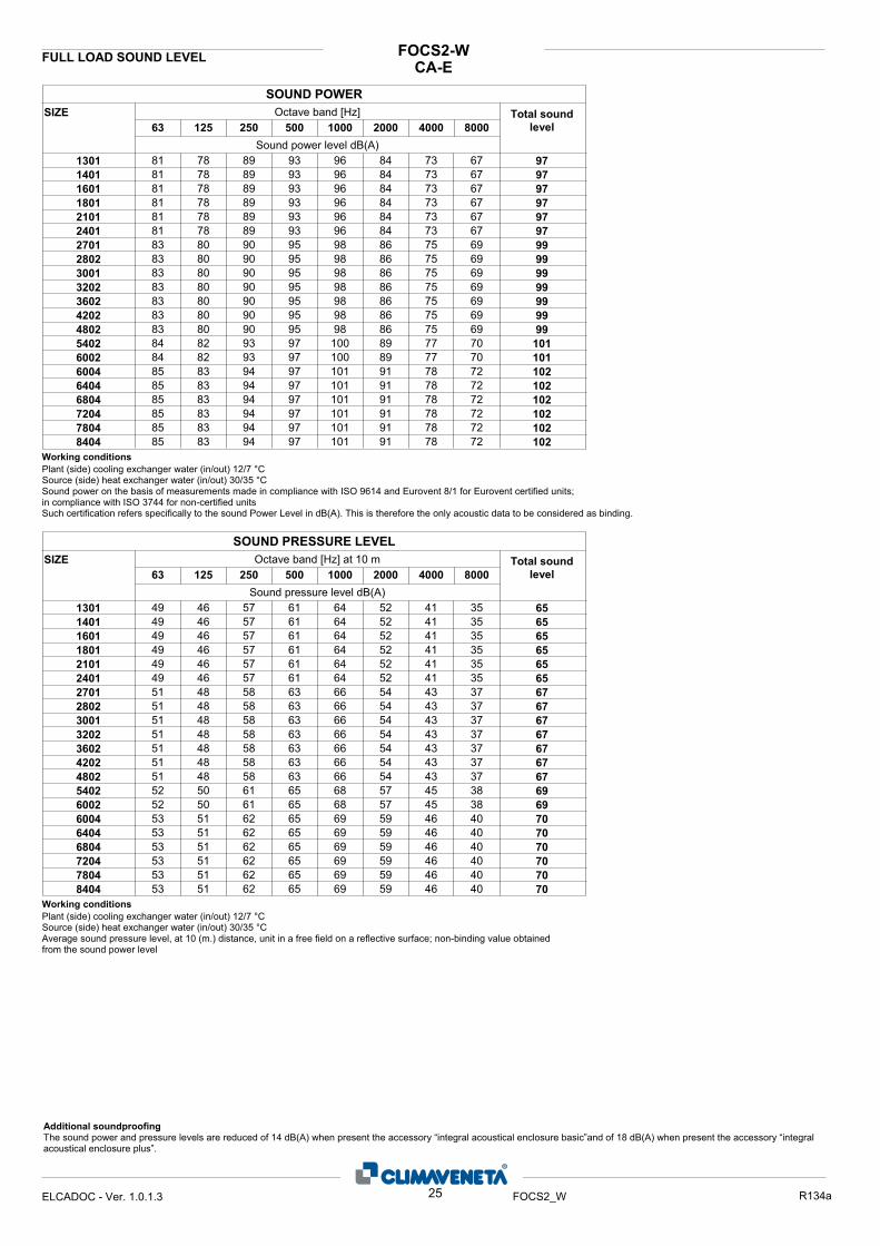
CA-EFOCS2-WFULL LOAD SOUND LEVEL
SIZE Octave band [Hz]2000100050025012563 80004000
Total sound level
Sound power level dB(A)
SOUND POWER
81 78 89 93 96 84 73 67 97130181 78 89 93 96 84 73 67 97140181 78 89 93 96 84 73 67 97160181 78 89 93 96 84 73 67 97180181 78 89 93 96 84 73 67 97210181 78 89 93 96 84 73 67 97240183 80 90 95 98 86 75 69 99270183 80 90 95 98 86 75 69 99280283 80 90 95 98 86 75 69 99300183 80 90 95 98 86 75 69 99320283 80 90 95 98 86 75 69 99360283 80 90 95 98 86 75 69 99420283 80 90 95 98 86 75 69 99480284 82 93 97 100 89 77 70 101540284 82 93 97 100 89 77 70 101600285 83 94 97 101 91 78 72 102600485 83 94 97 101 91 78 72 102640485 83 94 97 101 91 78 72 102680485 83 94 97 101 91 78 72 102720485 83 94 97 101 91 78 72 102780485 83 94 97 101 91 78 72 1028404
Plant (side) cooling exchanger water (in/out) 12/7 °CSource (side) heat exchanger water (in/out) 30/35 °CSound power on the basis of measurements made in compliance with ISO 9614 and Eurovent 8/1 for Eurovent certified units; in compliance with ISO 3744 for non-certified units Such certification refers specifically to the sound Power Level in dB(A). This is therefore the only acoustic data to be considered as binding.
Working conditions
SIZE Octave band [Hz] at 10 m2000100050025012563 80004000
Total sound level
Sound pressure level dB(A)
SOUND PRESSURE LEVEL
49 46 57 61 64 52 41 35 65130149 46 57 61 64 52 41 35 65140149 46 57 61 64 52 41 35 65160149 46 57 61 64 52 41 35 65180149 46 57 61 64 52 41 35 65210149 46 57 61 64 52 41 35 65240151 48 58 63 66 54 43 37 67270151 48 58 63 66 54 43 37 67280251 48 58 63 66 54 43 37 67300151 48 58 63 66 54 43 37 67320251 48 58 63 66 54 43 37 67360251 48 58 63 66 54 43 37 67420251 48 58 63 66 54 43 37 67480252 50 61 65 68 57 45 38 69540252 50 61 65 68 57 45 38 69600253 51 62 65 69 59 46 40 70600453 51 62 65 69 59 46 40 70640453 51 62 65 69 59 46 40 70680453 51 62 65 69 59 46 40 70720453 51 62 65 69 59 46 40 70780453 51 62 65 69 59 46 40 708404
Plant (side) cooling exchanger water (in/out) 12/7 °CSource (side) heat exchanger water (in/out) 30/35 °CAverage sound pressure level, at 10 (m.) distance, unit in a free field on a reflective surface; non-binding value obtained from the sound power level
Working conditions
25ELCADOC - Ver. 1.0.1.3 FOCS2_W R134a
Additional soundproofing The sound power and pressure levels are reduced of 14 dB(A) when present the accessory “integral acoustical enclosure basic”and of 18 dB(A) when present the accessory “integral acoustical enclosure plus”.
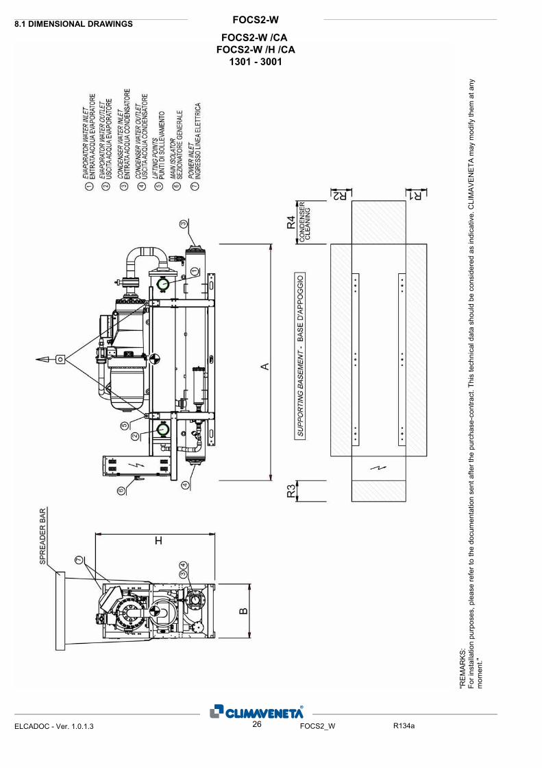
FOCS2-W8.1 DIMENSIONAL DRAWINGS
"RE
MA
RK
S:Fo
r ins
talla
tion
purp
oses
, ple
ase
refe
r to
the
docu
men
tatio
n se
nt a
fter t
he p
urch
ase-
cont
ract
. Thi
s te
chni
cal d
ata
shou
ld b
e co
nsid
ered
as
indi
cativ
e. C
LIM
AV
EN
ETA
may
mod
ify th
em a
t any
m
omen
t."
26ELCADOC - Ver. 1.0.1.3 FOCS2_W R134a
FOCS2-W /CA FOCS2-W /H /CA
1301 - 3001
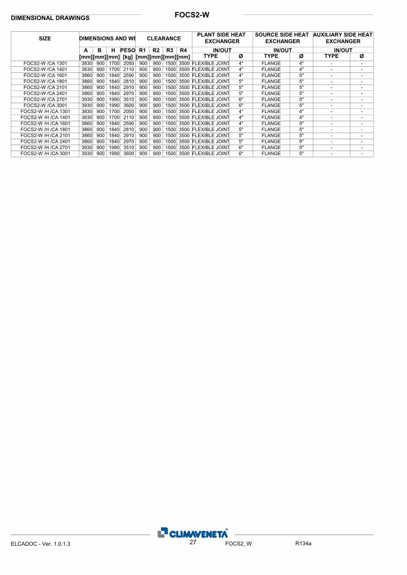
FOCS2-WDIMENSIONAL DRAWINGS
ØIN/OUT
ØIN/OUTIN/OUTR4
[mm]
R3
[mm]
R2
[mm]
R1
[mm]
PESO
[kg]
H
[mm]
B
[mm]
A
[mm]
SIZE DIMENSIONS AND WE CLEARANCEPLANT SIDE HEAT
EXCHANGER
ØTYPE TYPE TYPE
SOURCE SIDE HEAT
EXCHANGER
AUXILIARY SIDE HEAT
EXCHANGER
3830 900 1700 2050 900 900 1500 3500 FLEXIBLE JOINT 4" FLANGE 4" - -FOCS2-W /CA 13013830 900 1700 2110 900 900 1500 3500 FLEXIBLE JOINT 4" FLANGE 4" - -FOCS2-W /CA 14013860 900 1840 2590 900 900 1500 3500 FLEXIBLE JOINT 4" FLANGE 5" - -FOCS2-W /CA 16013860 900 1840 2810 900 900 1500 3500 FLEXIBLE JOINT 5" FLANGE 5" - -FOCS2-W /CA 18013860 900 1840 2910 900 900 1500 3500 FLEXIBLE JOINT 5" FLANGE 5" - -FOCS2-W /CA 21013860 900 1840 2970 900 900 1500 3500 FLEXIBLE JOINT 5" FLANGE 5" - -FOCS2-W /CA 24013930 900 1990 3510 900 900 1500 3500 FLEXIBLE JOINT 6" FLANGE 5" - -FOCS2-W /CA 27013930 900 1990 3600 900 900 1500 3500 FLEXIBLE JOINT 6" FLANGE 5" - -FOCS2-W /CA 30013830 900 1700 2050 900 900 1500 3500 FLEXIBLE JOINT 4" FLANGE 4" - -FOCS2-W /H /CA 13013830 900 1700 2110 900 900 1500 3500 FLEXIBLE JOINT 4" FLANGE 4" - -FOCS2-W /H /CA 14013860 900 1840 2590 900 900 1500 3500 FLEXIBLE JOINT 4" FLANGE 5" - -FOCS2-W /H /CA 16013860 900 1840 2810 900 900 1500 3500 FLEXIBLE JOINT 5" FLANGE 5" - -FOCS2-W /H /CA 18013860 900 1840 2910 900 900 1500 3500 FLEXIBLE JOINT 5" FLANGE 5" - -FOCS2-W /H /CA 21013860 900 1840 2970 900 900 1500 3500 FLEXIBLE JOINT 5" FLANGE 5" - -FOCS2-W /H /CA 24013930 900 1990 3510 900 900 1500 3500 FLEXIBLE JOINT 6" FLANGE 5" - -FOCS2-W /H /CA 27013930 900 1990 3600 900 900 1500 3500 FLEXIBLE JOINT 6" FLANGE 5" - -FOCS2-W /H /CA 3001
27ELCADOC - Ver. 1.0.1.3 FOCS2_W R134a
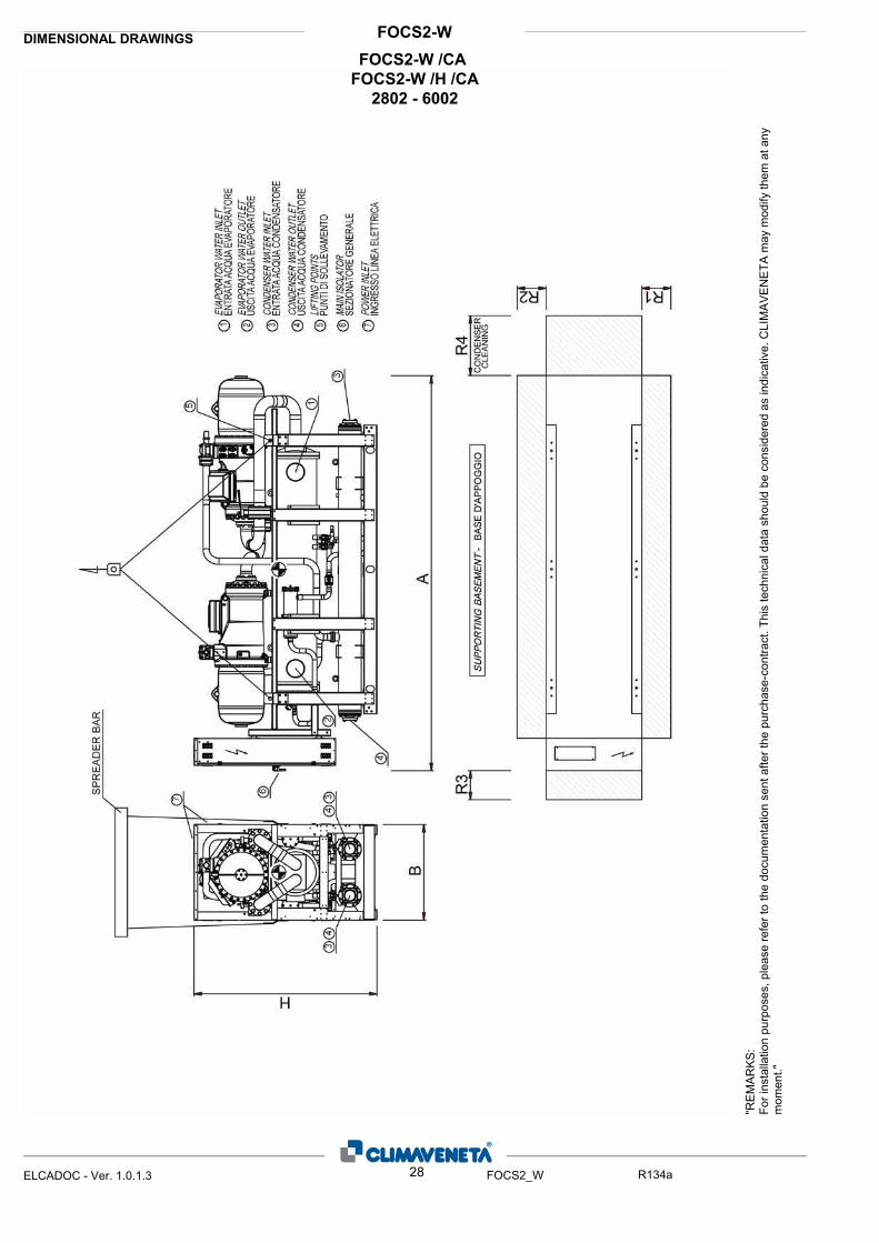
FOCS2-WDIMENSIONAL DRAWINGS
"RE
MA
RK
S:Fo
r ins
talla
tion
purp
oses
, ple
ase
refe
r to
the
docu
men
tatio
n se
nt a
fter t
he p
urch
ase-
cont
ract
. Thi
s te
chni
cal d
ata
shou
ld b
e co
nsid
ered
as
indi
cativ
e. C
LIM
AV
EN
ETA
may
mod
ify th
em a
t any
m
omen
t."
28ELCADOC - Ver. 1.0.1.3 FOCS2_W R134a
FOCS2-W /CA FOCS2-W /H /CA
2802 - 6002

FOCS2-WDIMENSIONAL DRAWINGS
ØIN/OUT
ØIN/OUTIN/OUTR4
[mm]
R3
[mm]
R2
[mm]
R1
[mm]
PESO
[kg]
H
[mm]
B
[mm]
A
[mm]
SIZE DIMENSIONS AND WE CLEARANCEPLANT SIDE HEAT
EXCHANGER
ØTYPE TYPE TYPE
SOURCE SIDE HEAT
EXCHANGER
AUXILIARY SIDE HEAT
EXCHANGER
4200 1150 2050 4120 900 900 1500 3500 FLEXIBLE JOINT 6" FLANGE 4" - -FOCS2-W /CA 28024750 1150 2050 5110 900 900 1500 3000 FLEXIBLE JOINT 6" FLANGE 5" - -FOCS2-W /CA 32024750 1150 2050 5400 900 900 1500 3000 FLEXIBLE JOINT 6" FLANGE 5" - -FOCS2-W /CA 36024750 1150 2200 6070 900 900 1500 3000 FLEXIBLE JOINT 8" FLANGE 5" - -FOCS2-W /CA 42024750 1150 2200 6120 900 900 1500 3000 FLEXIBLE JOINT 8" FLANGE 5" - -FOCS2-W /CA 45024750 1150 2200 6180 900 900 1500 3000 FLEXIBLE JOINT 8" FLANGE 5" - -FOCS2-W /CA 48024850 1150 2200 6950 900 900 1500 3000 FLEXIBLE JOINT 8" FLANGE 5" - -FOCS2-W /CA 54024850 1150 2200 7090 900 900 1500 3000 FLEXIBLE JOINT 8" FLANGE 5" - -FOCS2-W /CA 60024200 1150 2050 4120 900 900 1500 3500 FLEXIBLE JOINT 6" FLANGE 4" - -FOCS2-W /H /CA 28024750 1150 2050 5110 900 900 1500 3000 FLEXIBLE JOINT 6" FLANGE 5" - -FOCS2-W /H /CA 32024750 1150 2050 5400 900 900 1500 3000 FLEXIBLE JOINT 6" FLANGE 5" - -FOCS2-W /H /CA 36024750 1150 2200 6070 900 900 1500 3000 FLEXIBLE JOINT 8" FLANGE 5" - -FOCS2-W /H /CA 42024750 1150 2200 6120 900 900 1500 3000 FLEXIBLE JOINT 8" FLANGE 5" - -FOCS2-W /H /CA 45024750 1150 2200 6180 900 900 1500 3000 FLEXIBLE JOINT 8" FLANGE 5" - -FOCS2-W /H /CA 48024850 1150 2200 6950 900 900 1500 3000 FLEXIBLE JOINT 8" FLANGE 5" - -FOCS2-W /H /CA 54024850 1150 2200 7090 900 900 1500 3000 FLEXIBLE JOINT 8" FLANGE 5" - -FOCS2-W /H /CA 6002
29ELCADOC - Ver. 1.0.1.3 FOCS2_W R134a

FOCS2-WDIMENSIONAL DRAWINGS
"RE
MA
RK
S:Fo
r ins
talla
tion
purp
oses
, ple
ase
refe
r to
the
docu
men
tatio
n se
nt a
fter t
he p
urch
ase-
cont
ract
. Thi
s te
chni
cal d
ata
shou
ld b
e co
nsid
ered
as
indi
cativ
e. C
LIM
AV
EN
ETA
may
mod
ify th
em a
t any
m
omen
t."
30ELCADOC - Ver. 1.0.1.3 FOCS2_W R134a
FOCS2-W /CA FOCS2-W /H /CA
6303 - 9003
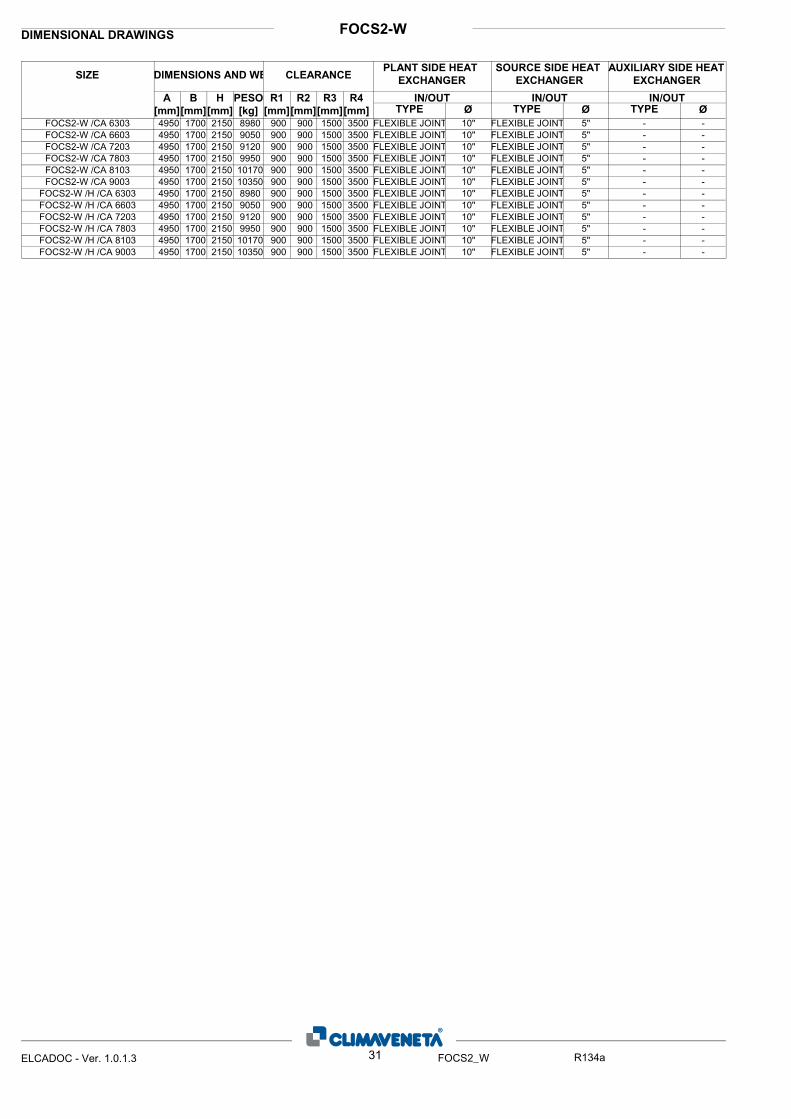
FOCS2-WDIMENSIONAL DRAWINGS
ØIN/OUT
ØIN/OUTIN/OUTR4
[mm]
R3
[mm]
R2
[mm]
R1
[mm]
PESO
[kg]
H
[mm]
B
[mm]
A
[mm]
SIZE DIMENSIONS AND WE CLEARANCEPLANT SIDE HEAT
EXCHANGER
ØTYPE TYPE TYPE
SOURCE SIDE HEAT
EXCHANGER
AUXILIARY SIDE HEAT
EXCHANGER
4950 1700 2150 8980 900 900 1500 3500 FLEXIBLE JOINT 10" FLEXIBLE JOINT 5" - -FOCS2-W /CA 63034950 1700 2150 9050 900 900 1500 3500 FLEXIBLE JOINT 10" FLEXIBLE JOINT 5" - -FOCS2-W /CA 66034950 1700 2150 9120 900 900 1500 3500 FLEXIBLE JOINT 10" FLEXIBLE JOINT 5" - -FOCS2-W /CA 72034950 1700 2150 9950 900 900 1500 3500 FLEXIBLE JOINT 10" FLEXIBLE JOINT 5" - -FOCS2-W /CA 78034950 1700 2150 10170 900 900 1500 3500 FLEXIBLE JOINT 10" FLEXIBLE JOINT 5" - -FOCS2-W /CA 81034950 1700 2150 10350 900 900 1500 3500 FLEXIBLE JOINT 10" FLEXIBLE JOINT 5" - -FOCS2-W /CA 90034950 1700 2150 8980 900 900 1500 3500 FLEXIBLE JOINT 10" FLEXIBLE JOINT 5" - -FOCS2-W /H /CA 63034950 1700 2150 9050 900 900 1500 3500 FLEXIBLE JOINT 10" FLEXIBLE JOINT 5" - -FOCS2-W /H /CA 66034950 1700 2150 9120 900 900 1500 3500 FLEXIBLE JOINT 10" FLEXIBLE JOINT 5" - -FOCS2-W /H /CA 72034950 1700 2150 9950 900 900 1500 3500 FLEXIBLE JOINT 10" FLEXIBLE JOINT 5" - -FOCS2-W /H /CA 78034950 1700 2150 10170 900 900 1500 3500 FLEXIBLE JOINT 10" FLEXIBLE JOINT 5" - -FOCS2-W /H /CA 81034950 1700 2150 10350 900 900 1500 3500 FLEXIBLE JOINT 10" FLEXIBLE JOINT 5" - -FOCS2-W /H /CA 9003
31ELCADOC - Ver. 1.0.1.3 FOCS2_W R134a
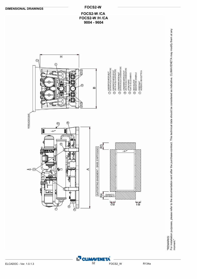
FOCS2-WDIMENSIONAL DRAWINGS
"RE
MA
RK
S:Fo
r ins
talla
tion
purp
oses
, ple
ase
refe
r to
the
docu
men
tatio
n se
nt a
fter t
he p
urch
ase-
cont
ract
. Thi
s te
chni
cal d
ata
shou
ld b
e co
nsid
ered
as
indi
cativ
e. C
LIM
AV
EN
ETA
may
mod
ify th
em a
t any
m
omen
t."
32ELCADOC - Ver. 1.0.1.3 FOCS2_W R134a
FOCS2-W /CA FOCS2-W /H /CA
9004 - 9604
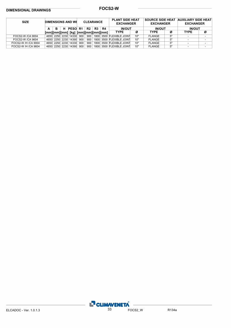
FOCS2-WDIMENSIONAL DRAWINGS
ØIN/OUT
ØIN/OUTIN/OUTR4
[mm]
R3
[mm]
R2
[mm]
R1
[mm]
PESO
[kg]
H
[mm]
B
[mm]
A
[mm]
SIZE DIMENSIONS AND WE CLEARANCEPLANT SIDE HEAT
EXCHANGER
ØTYPE TYPE TYPE
SOURCE SIDE HEAT
EXCHANGER
AUXILIARY SIDE HEAT
EXCHANGER
4650 2250 2230 14330 900 900 1800 3500 FLEXIBLE JOINT 10" FLANGE 5" - -FOCS2-W /CA 90044650 2250 2230 14390 900 900 1800 3500 FLEXIBLE JOINT 10" FLANGE 5" - -FOCS2-W /CA 96044650 2250 2230 14330 900 900 1800 3500 FLEXIBLE JOINT 10" FLANGE 5" - -FOCS2-W /H /CA 90044650 2250 2230 14390 900 900 1800 3500 FLEXIBLE JOINT 10" FLANGE 5" - -FOCS2-W /H /CA 9604
33ELCADOC - Ver. 1.0.1.3 FOCS2_W R134a
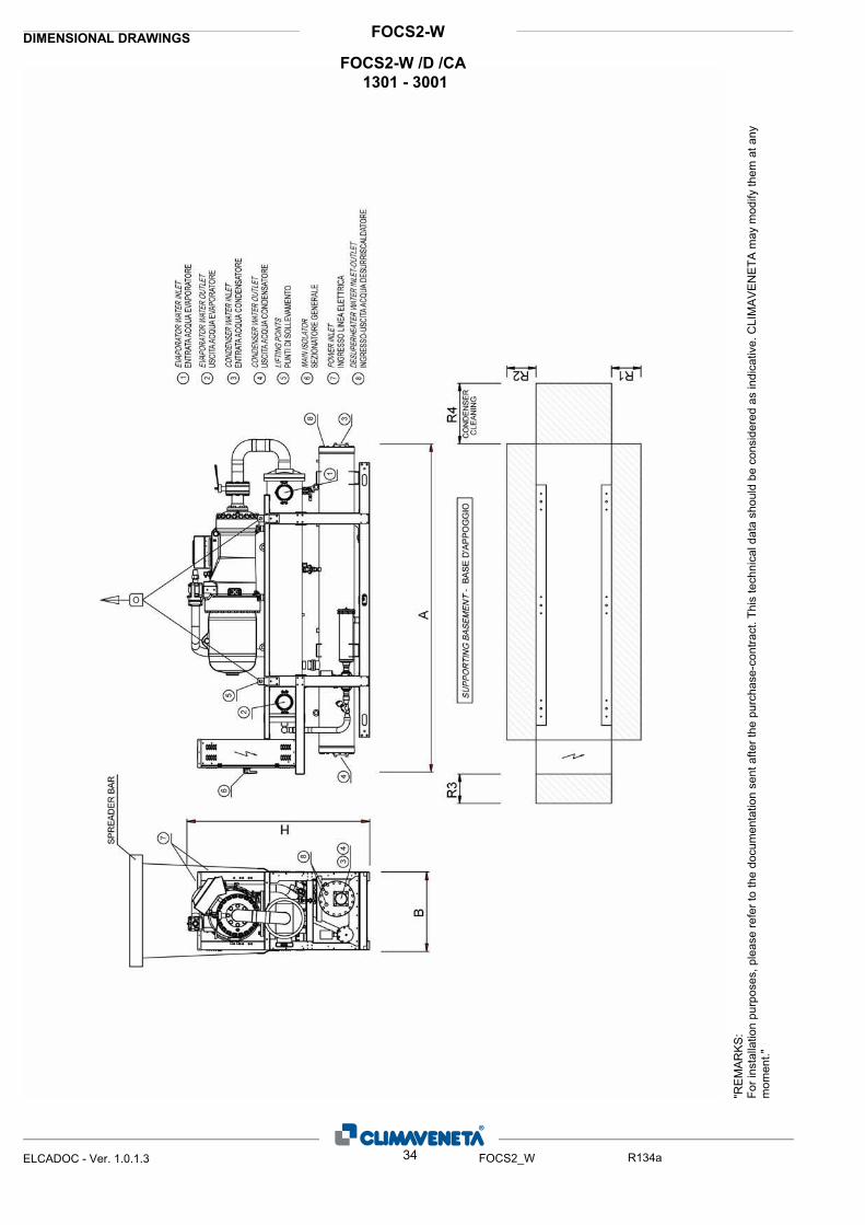
FOCS2-WDIMENSIONAL DRAWINGS
"RE
MA
RK
S:Fo
r ins
talla
tion
purp
oses
, ple
ase
refe
r to
the
docu
men
tatio
n se
nt a
fter t
he p
urch
ase-
cont
ract
. Thi
s te
chni
cal d
ata
shou
ld b
e co
nsid
ered
as
indi
cativ
e. C
LIM
AV
EN
ETA
may
mod
ify th
em a
t any
m
omen
t."
34ELCADOC - Ver. 1.0.1.3 FOCS2_W R134a
FOCS2-W /D /CA 1301 - 3001

FOCS2-WDIMENSIONAL DRAWINGS
ØIN/OUT
ØIN/OUTIN/OUTR4
[mm]
R3
[mm]
R2
[mm]
R1
[mm]
PESO
[kg]
H
[mm]
B
[mm]
A
[mm]
SIZE DIMENSIONS AND WE CLEARANCEPLANT SIDE HEAT
EXCHANGER
ØTYPE TYPE TYPE
SOURCE SIDE HEAT
EXCHANGER
AUXILIARY SIDE HEAT
EXCHANGER
3830 900 1700 2070 900 900 1500 3500 FLEXIBLE JOINT 4" FLANGE 4" GAS 1"FOCS2-W /D /CA 13013830 900 1700 2130 900 900 1500 3500 FLEXIBLE JOINT 4" FLANGE 4" GAS 1"FOCS2-W /D /CA 14013860 900 1840 2690 900 900 1500 3500 FLEXIBLE JOINT 4" FLANGE 5" GAS 1-1/4"FOCS2-W /D /CA 16013860 900 1840 2910 900 900 1500 3500 FLEXIBLE JOINT 5" FLANGE 5" GAS 1-1/4"FOCS2-W /D /CA 18013860 900 1840 3010 900 900 1500 3500 FLEXIBLE JOINT 5" FLANGE 5" GAS 1-1/4"FOCS2-W /D /CA 21013860 900 1840 3070 900 900 1500 3500 FLEXIBLE JOINT 5" FLANGE 5" GAS 1-1/4"FOCS2-W /D /CA 24013820 900 2110 3650 900 900 1500 3500 FLEXIBLE JOINT 6" FLANGE 5" GAS 1-1/4"FOCS2-W /D /CA 27013820 900 2110 3740 900 900 1500 3500 FLEXIBLE JOINT 6" FLANGE 5" GAS 1-1/4"FOCS2-W /D /CA 3001
35ELCADOC - Ver. 1.0.1.3 FOCS2_W R134a
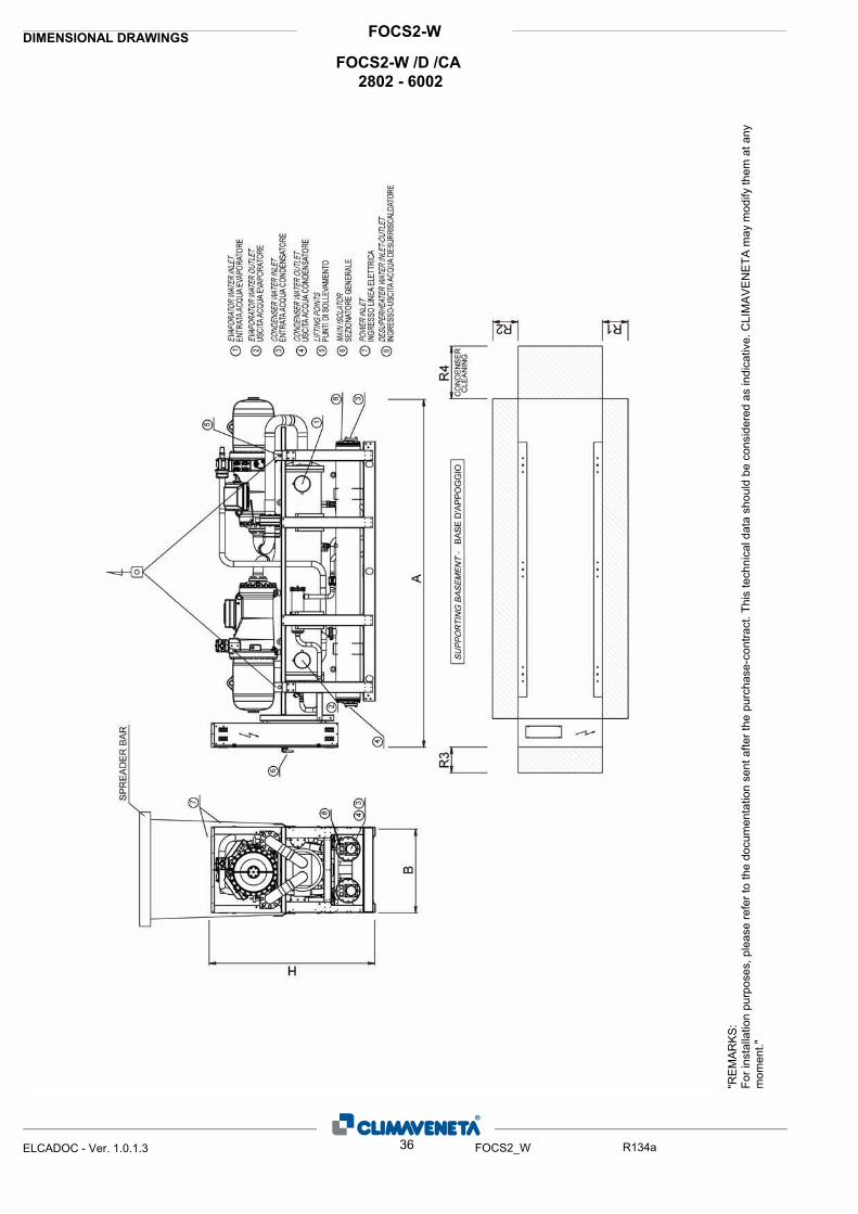
FOCS2-WDIMENSIONAL DRAWINGS
"RE
MA
RK
S:Fo
r ins
talla
tion
purp
oses
, ple
ase
refe
r to
the
docu
men
tatio
n se
nt a
fter t
he p
urch
ase-
cont
ract
. Thi
s te
chni
cal d
ata
shou
ld b
e co
nsid
ered
as
indi
cativ
e. C
LIM
AV
EN
ETA
may
mod
ify th
em a
t any
m
omen
t."
36ELCADOC - Ver. 1.0.1.3 FOCS2_W R134a
FOCS2-W /D /CA 2802 - 6002
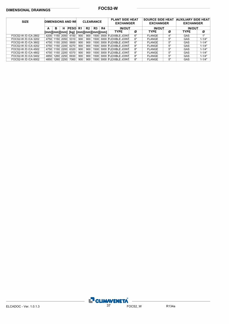
FOCS2-WDIMENSIONAL DRAWINGS
ØIN/OUT
ØIN/OUTIN/OUTR4
[mm]
R3
[mm]
R2
[mm]
R1
[mm]
PESO
[kg]
H
[mm]
B
[mm]
A
[mm]
SIZE DIMENSIONS AND WE CLEARANCEPLANT SIDE HEAT
EXCHANGER
ØTYPE TYPE TYPE
SOURCE SIDE HEAT
EXCHANGER
AUXILIARY SIDE HEAT
EXCHANGER
4200 1150 2050 4150 900 900 1500 3500 FLEXIBLE JOINT 6" FLANGE 4" GAS 1"FOCS2-W /D /CA 28024750 1150 2050 5310 900 900 1500 3000 FLEXIBLE JOINT 6" FLANGE 5" GAS 1-1/4"FOCS2-W /D /CA 32024750 1150 2050 5600 900 900 1500 3000 FLEXIBLE JOINT 6" FLANGE 5" GAS 1-1/4"FOCS2-W /D /CA 36024750 1150 2200 6270 900 900 1500 3000 FLEXIBLE JOINT 8" FLANGE 5" GAS 1-1/4"FOCS2-W /D /CA 42024750 1150 2200 6320 900 900 1500 3000 FLEXIBLE JOINT 8" FLANGE 5" GAS 1-1/4"FOCS2-W /D /CA 45024750 1150 2200 6370 900 900 1500 3000 FLEXIBLE JOINT 8" FLANGE 5" GAS 1-1/4"FOCS2-W /D /CA 48024850 1260 2250 6930 900 900 1500 3000 FLEXIBLE JOINT 8" FLANGE 5" GAS 1-1/4"FOCS2-W /D /CA 54024850 1260 2250 7060 900 900 1500 3000 FLEXIBLE JOINT 8" FLANGE 5" GAS 1-1/4"FOCS2-W /D /CA 6002
37ELCADOC - Ver. 1.0.1.3 FOCS2_W R134a

FOCS2-WDIMENSIONAL DRAWINGS
"RE
MA
RK
S:Fo
r ins
talla
tion
purp
oses
, ple
ase
refe
r to
the
docu
men
tatio
n se
nt a
fter t
he p
urch
ase-
cont
ract
. Thi
s te
chni
cal d
ata
shou
ld b
e co
nsid
ered
as
indi
cativ
e. C
LIM
AV
EN
ETA
may
mod
ify th
em a
t any
m
omen
t."
38ELCADOC - Ver. 1.0.1.3 FOCS2_W R134a
FOCS2-W /D /CA 6303 - 9003

FOCS2-WDIMENSIONAL DRAWINGS
ØIN/OUT
ØIN/OUTIN/OUTR4
[mm]
R3
[mm]
R2
[mm]
R1
[mm]
PESO
[kg]
H
[mm]
B
[mm]
A
[mm]
SIZE DIMENSIONS AND WE CLEARANCEPLANT SIDE HEAT
EXCHANGER
ØTYPE TYPE TYPE
SOURCE SIDE HEAT
EXCHANGER
AUXILIARY SIDE HEAT
EXCHANGER
4950 1700 2150 9280 900 900 1500 3500 FLEXIBLE JOINT 10" FLEXIBLE JOINT 5" GAS 1-1/4"FOCS2-W /D /CA 63034950 1700 2150 9330 900 900 1500 3500 FLEXIBLE JOINT 10" FLEXIBLE JOINT 5" GAS 1-1/4"FOCS2-W /D /CA 66034950 1700 2150 9420 900 900 1500 3500 FLEXIBLE JOINT 10" FLEXIBLE JOINT 5" GAS 1-1/4"FOCS2-W /D /CA 72034950 1700 2190 10360 900 900 1500 3500 FLEXIBLE JOINT 10" FLEXIBLE JOINT 5" GAS 1-1/4"FOCS2-W /D /CA 78034950 1700 2190 10620 900 900 1500 3500 FLEXIBLE JOINT 10" FLEXIBLE JOINT 5" GAS 1-1/4"FOCS2-W /D /CA 81034950 1700 2190 10810 900 900 1500 3500 FLEXIBLE JOINT 10" FLEXIBLE JOINT 5" GAS 1-1/4"FOCS2-W /D /CA 9003
39ELCADOC - Ver. 1.0.1.3 FOCS2_W R134a

FOCS2-WDIMENSIONAL DRAWINGS
"RE
MA
RK
S:Fo
r ins
talla
tion
purp
oses
, ple
ase
refe
r to
the
docu
men
tatio
n se
nt a
fter t
he p
urch
ase-
cont
ract
. Thi
s te
chni
cal d
ata
shou
ld b
e co
nsid
ered
as
indi
cativ
e. C
LIM
AV
EN
ETA
may
mod
ify th
em a
t any
m
omen
t."
40ELCADOC - Ver. 1.0.1.3 FOCS2_W R134a
FOCS2-W /D /CA 9004 - 9604
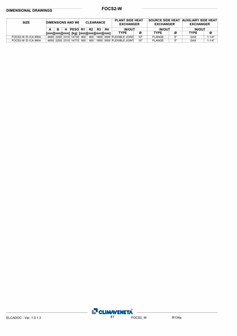
FOCS2-WDIMENSIONAL DRAWINGS
ØIN/OUT
ØIN/OUTIN/OUTR4
[mm]
R3
[mm]
R2
[mm]
R1
[mm]
PESO
[kg]
H
[mm]
B
[mm]
A
[mm]
SIZE DIMENSIONS AND WE CLEARANCEPLANT SIDE HEAT
EXCHANGER
ØTYPE TYPE TYPE
SOURCE SIDE HEAT
EXCHANGER
AUXILIARY SIDE HEAT
EXCHANGER
4650 2250 2310 14730 900 900 1800 3500 FLEXIBLE JOINT 10" FLANGE 5" GAS 1-1/4"FOCS2-W /D /CA 90044650 2250 2310 14770 900 900 1800 3500 FLEXIBLE JOINT 10" FLANGE 5" GAS 1-1/4"FOCS2-W /D /CA 9604
41ELCADOC - Ver. 1.0.1.3 FOCS2_W R134a

FOCS2-WDIMENSIONAL DRAWINGS
"RE
MA
RK
S:Fo
r ins
talla
tion
purp
oses
, ple
ase
refe
r to
the
docu
men
tatio
n se
nt a
fter t
he p
urch
ase-
cont
ract
. Thi
s te
chni
cal d
ata
shou
ld b
e co
nsid
ered
as
indi
cativ
e. C
LIM
AV
EN
ETA
may
mod
ify th
em a
t any
m
omen
t."
42ELCADOC - Ver. 1.0.1.3 FOCS2_W R134a
FOCS2-W /R /CA 1301 - 3001
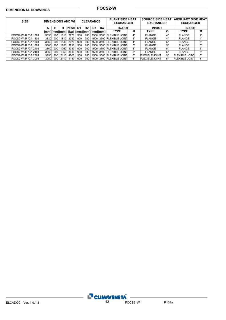
FOCS2-WDIMENSIONAL DRAWINGS
ØIN/OUT
ØIN/OUTIN/OUTR4
[mm]
R3
[mm]
R2
[mm]
R1
[mm]
PESO
[kg]
H
[mm]
B
[mm]
A
[mm]
SIZE DIMENSIONS AND WE CLEARANCEPLANT SIDE HEAT
EXCHANGER
ØTYPE TYPE TYPE
SOURCE SIDE HEAT
EXCHANGER
AUXILIARY SIDE HEAT
EXCHANGER
3830 900 1810 2270 900 900 1500 3500 FLEXIBLE JOINT 4" FLANGE 4" FLANGE 4"FOCS2-W /R /CA 13013830 900 1810 2380 900 900 1500 3500 FLEXIBLE JOINT 4" FLANGE 4" FLANGE 4"FOCS2-W /R /CA 14013860 900 1840 2970 900 900 1500 3500 FLEXIBLE JOINT 4" FLANGE 5" FLANGE 5"FOCS2-W /R /CA 16013860 900 1950 3210 900 900 1500 3500 FLEXIBLE JOINT 5" FLANGE 5" FLANGE 5"FOCS2-W /R /CA 18013860 900 1950 3330 900 900 1500 3500 FLEXIBLE JOINT 5" FLANGE 5" FLANGE 5"FOCS2-W /R /CA 21013860 900 1950 3410 900 900 1500 3500 FLEXIBLE JOINT 5" FLANGE 5" FLANGE 5"FOCS2-W /R /CA 24013950 900 2110 4000 900 900 1500 3500 FLEXIBLE JOINT 6" FLEXIBLE JOINT 5" FLEXIBLE JOINT 5"FOCS2-W /R /CA 27013950 900 2110 4130 900 900 1500 3500 FLEXIBLE JOINT 6" FLEXIBLE JOINT 5" FLEXIBLE JOINT 5"FOCS2-W /R /CA 3001
43ELCADOC - Ver. 1.0.1.3 FOCS2_W R134a

FOCS2-WDIMENSIONAL DRAWINGS
"RE
MA
RK
S:Fo
r ins
talla
tion
purp
oses
, ple
ase
refe
r to
the
docu
men
tatio
n se
nt a
fter t
he p
urch
ase-
cont
ract
. Thi
s te
chni
cal d
ata
shou
ld b
e co
nsid
ered
as
indi
cativ
e. C
LIM
AV
EN
ETA
may
mod
ify th
em a
t any
m
omen
t."
44ELCADOC - Ver. 1.0.1.3 FOCS2_W R134a
FOCS2-W /R /CA 2802 - 6002

FOCS2-WDIMENSIONAL DRAWINGS
ØIN/OUT
ØIN/OUTIN/OUTR4
[mm]
R3
[mm]
R2
[mm]
R1
[mm]
PESO
[kg]
H
[mm]
B
[mm]
A
[mm]
SIZE DIMENSIONS AND WE CLEARANCEPLANT SIDE HEAT
EXCHANGER
ØTYPE TYPE TYPE
SOURCE SIDE HEAT
EXCHANGER
AUXILIARY SIDE HEAT
EXCHANGER
4210 1150 2135 4120 900 900 1500 3500 FLEXIBLE JOINT 6" FLANGE 4" FLANGE 4"FOCS2-W /R /CA 28024750 1260 2250 5900 900 900 1500 3000 FLEXIBLE JOINT 6" FLANGE 5" FLANGE 5"FOCS2-W /R /CA 32024750 1260 2250 6210 900 900 1500 3000 FLEXIBLE JOINT 6" FLANGE 5" FLANGE 5"FOCS2-W /R /CA 36024750 1260 2250 6910 900 900 1500 3000 FLEXIBLE JOINT 8" FLANGE 5" FLANGE 5"FOCS2-W /R /CA 42024750 1260 2250 6990 900 900 1500 3000 FLEXIBLE JOINT 8" FLANGE 5" FLANGE 5"FOCS2-W /R /CA 45024750 1260 2250 7250 900 900 1500 3000 FLEXIBLE JOINT 8" FLANGE 5" FLANGE 5"FOCS2-W /R /CA 48024850 1260 2250 7790 900 900 1500 3000 FLEXIBLE JOINT 8" FLEXIBLE JOINT 5" FLEXIBLE JOINT 5"FOCS2-W /R /CA 54024850 1260 2250 7900 900 900 1500 3000 FLEXIBLE JOINT 8" FLEXIBLE JOINT 5" FLEXIBLE JOINT 5"FOCS2-W /R /CA 6002
45ELCADOC - Ver. 1.0.1.3 FOCS2_W R134a
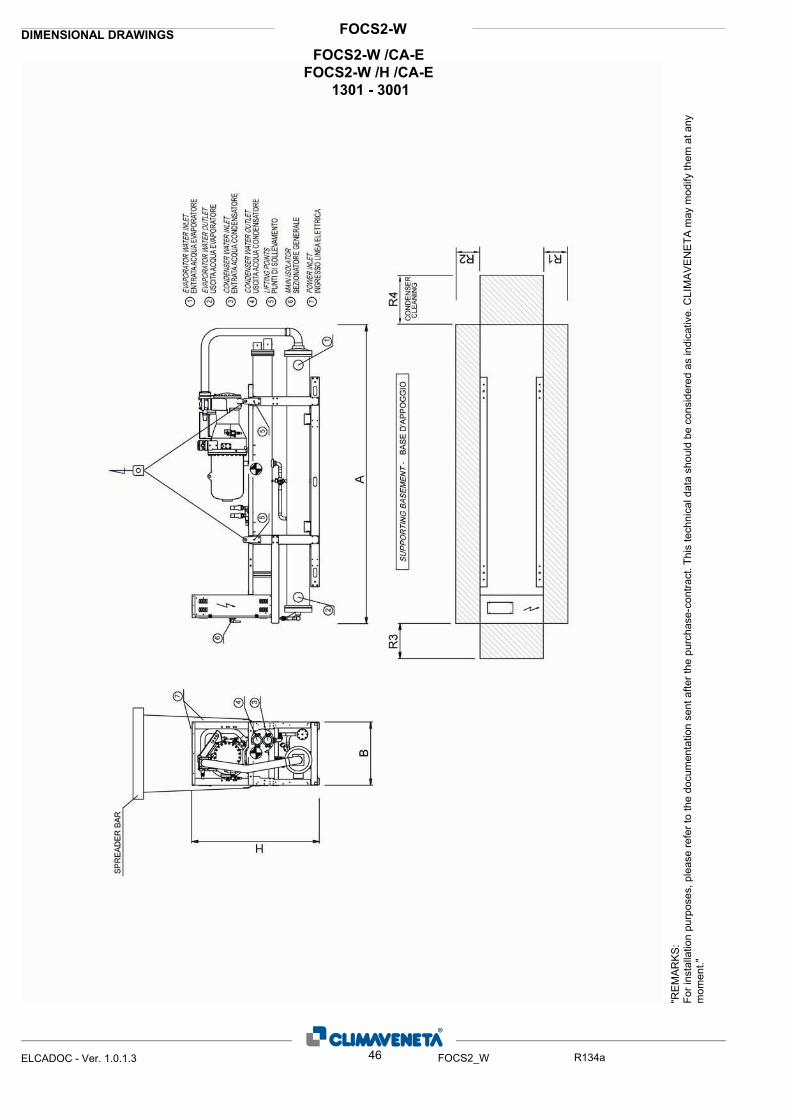
FOCS2-WDIMENSIONAL DRAWINGS
"RE
MA
RK
S:Fo
r ins
talla
tion
purp
oses
, ple
ase
refe
r to
the
docu
men
tatio
n se
nt a
fter t
he p
urch
ase-
cont
ract
. Thi
s te
chni
cal d
ata
shou
ld b
e co
nsid
ered
as
indi
cativ
e. C
LIM
AV
EN
ETA
may
mod
ify th
em a
t any
m
omen
t."
46ELCADOC - Ver. 1.0.1.3 FOCS2_W R134a
FOCS2-W /CA-E FOCS2-W /H /CA-E
1301 - 3001
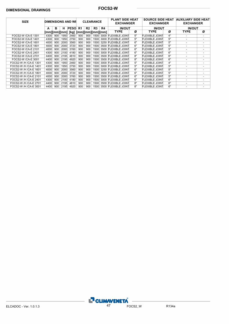
FOCS2-WDIMENSIONAL DRAWINGS
ØIN/OUT
ØIN/OUTIN/OUTR4
[mm]
R3
[mm]
R2
[mm]
R1
[mm]
PESO
[kg]
H
[mm]
B
[mm]
A
[mm]
SIZE DIMENSIONS AND WE CLEARANCEPLANT SIDE HEAT
EXCHANGER
ØTYPE TYPE TYPE
SOURCE SIDE HEAT
EXCHANGER
AUXILIARY SIDE HEAT
EXCHANGER
4300 900 1950 2460 900 900 1500 3000 FLEXIBLE JOINT 5" FLEXIBLE JOINT 4" - -FOCS2-W /CA-E 13014300 900 1950 2750 900 900 1500 3000 FLEXIBLE JOINT 5" FLEXIBLE JOINT 5" - -FOCS2-W /CA-E 14014000 900 2000 3560 900 900 1500 3250 FLEXIBLE JOINT 6" FLEXIBLE JOINT 5" - -FOCS2-W /CA-E 16014000 900 2000 3720 900 900 1500 3500 FLEXIBLE JOINT 6" FLEXIBLE JOINT 5" - -FOCS2-W /CA-E 18014000 900 2000 3760 900 900 1500 3500 FLEXIBLE JOINT 6" FLEXIBLE JOINT 5" - -FOCS2-W /CA-E 21014300 900 2100 4180 900 900 1500 3000 FLEXIBLE JOINT 6" FLEXIBLE JOINT 6" - -FOCS2-W /CA-E 24014400 900 2195 4810 900 900 1500 3500 FLEXIBLE JOINT 8" FLEXIBLE JOINT 6" - -FOCS2-W /CA-E 27014400 900 2195 4920 900 900 1500 3500 FLEXIBLE JOINT 8" FLEXIBLE JOINT 6" - -FOCS2-W /CA-E 30014300 900 1950 2460 900 900 1500 3000 FLEXIBLE JOINT 5" FLEXIBLE JOINT 4" - -FOCS2-W /H /CA-E 13014300 900 1950 2750 900 900 1500 3000 FLEXIBLE JOINT 5" FLEXIBLE JOINT 5" - -FOCS2-W /H /CA-E 14014000 900 2000 3560 900 900 1500 3250 FLEXIBLE JOINT 6" FLEXIBLE JOINT 5" - -FOCS2-W /H /CA-E 16014000 900 2000 3720 900 900 1500 3500 FLEXIBLE JOINT 6" FLEXIBLE JOINT 5" - -FOCS2-W /H /CA-E 18014000 900 2000 3760 900 900 1500 3500 FLEXIBLE JOINT 6" FLEXIBLE JOINT 5" - -FOCS2-W /H /CA-E 21014300 900 2100 4180 900 900 1500 3000 FLEXIBLE JOINT 6" FLEXIBLE JOINT 6" - -FOCS2-W /H /CA-E 24014400 900 2195 4810 900 900 1500 3500 FLEXIBLE JOINT 8" FLEXIBLE JOINT 6" - -FOCS2-W /H /CA-E 27014400 900 2195 4920 900 900 1500 3500 FLEXIBLE JOINT 8" FLEXIBLE JOINT 6" - -FOCS2-W /H /CA-E 3001
47ELCADOC - Ver. 1.0.1.3 FOCS2_W R134a
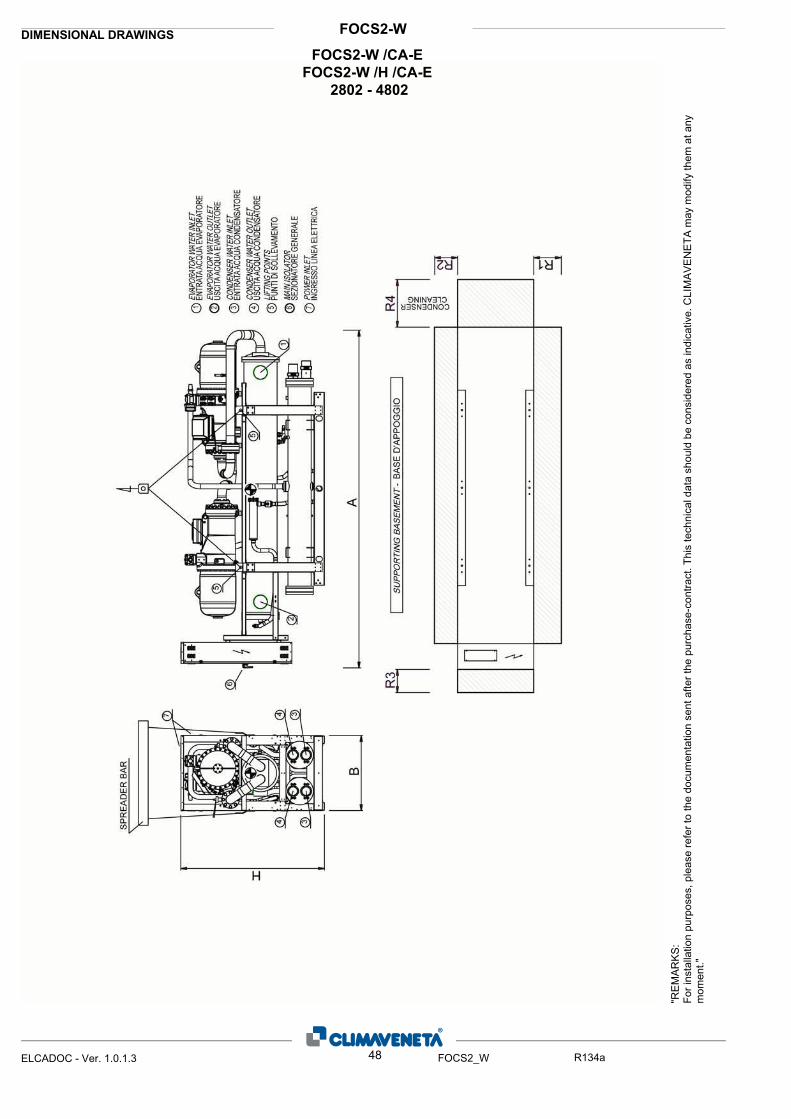
FOCS2-WDIMENSIONAL DRAWINGS
"RE
MA
RK
S:Fo
r ins
talla
tion
purp
oses
, ple
ase
refe
r to
the
docu
men
tatio
n se
nt a
fter t
he p
urch
ase-
cont
ract
. Thi
s te
chni
cal d
ata
shou
ld b
e co
nsid
ered
as
indi
cativ
e. C
LIM
AV
EN
ETA
may
mod
ify th
em a
t any
m
omen
t."
48ELCADOC - Ver. 1.0.1.3 FOCS2_W R134a
FOCS2-W /CA-E FOCS2-W /H /CA-E
2802 - 4802

FOCS2-WDIMENSIONAL DRAWINGS
ØIN/OUT
ØIN/OUTIN/OUTR4
[mm]
R3
[mm]
R2
[mm]
R1
[mm]
PESO
[kg]
H
[mm]
B
[mm]
A
[mm]
SIZE DIMENSIONS AND WE CLEARANCEPLANT SIDE HEAT
EXCHANGER
ØTYPE TYPE TYPE
SOURCE SIDE HEAT
EXCHANGER
AUXILIARY SIDE HEAT
EXCHANGER
4600 1150 2195 5360 900 900 1500 3000 FLEXIBLE JOINT 8" FLEXIBLE JOINT 5" - -FOCS2-W /CA-E 28024950 1150 2195 6410 900 900 1500 2750 FLEXIBLE JOINT 8" FLEXIBLE JOINT 5" - -FOCS2-W /CA-E 32025220 1150 2195 6870 900 900 1500 2750 FLEXIBLE JOINT 8" FLEXIBLE JOINT 5" - -FOCS2-W /CA-E 36024920 1150 2350 7850 900 900 1500 2750 FLEXIBLE JOINT 10" FLEXIBLE JOINT 5" - -FOCS2-W /CA-E 42024920 1285 2430 8470 900 900 1500 2750 FLEXIBLE JOINT 10" FLEXIBLE JOINT 6" - -FOCS2-W /CA-E 48024600 1150 2195 5360 900 900 1500 3000 FLEXIBLE JOINT 8" FLEXIBLE JOINT 5" - -FOCS2-W /H /CA-E 28024950 1150 2195 6410 900 900 1500 2750 FLEXIBLE JOINT 8" FLEXIBLE JOINT 5" - -FOCS2-W /H /CA-E 32025220 1150 2195 6870 900 900 1500 2750 FLEXIBLE JOINT 8" FLEXIBLE JOINT 5" - -FOCS2-W /H /CA-E 36024920 1150 2350 7850 900 900 1500 2750 FLEXIBLE JOINT 10" FLEXIBLE JOINT 5" - -FOCS2-W /H /CA-E 42024920 1285 2430 8470 900 900 1500 2750 FLEXIBLE JOINT 10" FLEXIBLE JOINT 6" - -FOCS2-W /H /CA-E 4802
49ELCADOC - Ver. 1.0.1.3 FOCS2_W R134a

FOCS2-WDIMENSIONAL DRAWINGS
"RE
MA
RK
S:Fo
r ins
talla
tion
purp
oses
, ple
ase
refe
r to
the
docu
men
tatio
n se
nt a
fter t
he p
urch
ase-
cont
ract
. Thi
s te
chni
cal d
ata
shou
ld b
e co
nsid
ered
as
indi
cativ
e. C
LIM
AV
EN
ETA
may
mod
ify th
em a
t any
m
omen
t."
50ELCADOC - Ver. 1.0.1.3 FOCS2_W R134a
FOCS2-W /D /CA-E 1301 - 3001

FOCS2-WDIMENSIONAL DRAWINGS
ØIN/OUT
ØIN/OUTIN/OUTR4
[mm]
R3
[mm]
R2
[mm]
R1
[mm]
PESO
[kg]
H
[mm]
B
[mm]
A
[mm]
SIZE DIMENSIONS AND WE CLEARANCEPLANT SIDE HEAT
EXCHANGER
ØTYPE TYPE TYPE
SOURCE SIDE HEAT
EXCHANGER
AUXILIARY SIDE HEAT
EXCHANGER
4300 900 1950 2650 900 900 1500 3250 FLEXIBLE JOINT 5" FLEXIBLE JOINT 5" GAS 1"1/4FOCS2-W /D /CA-E 13014300 900 1950 2770 900 900 1500 3000 FLEXIBLE JOINT 5" FLEXIBLE JOINT 5" GAS 1"1/4FOCS2-W /D /CA-E 14014000 900 2000 3590 900 900 1500 3250 FLEXIBLE JOINT 6" FLEXIBLE JOINT 5" GAS 1"1/4FOCS2-W /D /CA-E 16014000 900 2000 3750 900 900 1500 3500 FLEXIBLE JOINT 6" FLEXIBLE JOINT 5" GAS 1"1/4FOCS2-W /D /CA-E 18014000 900 2000 3790 900 900 1500 3500 FLEXIBLE JOINT 6" FLEXIBLE JOINT 5" GAS 1"1/4FOCS2-W /D /CA-E 21014300 900 2100 4210 900 900 1500 3000 FLEXIBLE JOINT 6" FLEXIBLE JOINT 5" GAS 1"1/4FOCS2-W /D /CA-E 24014400 900 2195 4810 900 900 1500 3500 FLEXIBLE JOINT 8" FLEXIBLE JOINT 5" GAS 1"1/4FOCS2-W /D /CA-E 27014400 900 2195 4920 900 900 1500 3500 FLEXIBLE JOINT 8" FLEXIBLE JOINT 5" GAS 1"1/4FOCS2-W /D /CA-E 3001
51ELCADOC - Ver. 1.0.1.3 FOCS2_W R134a
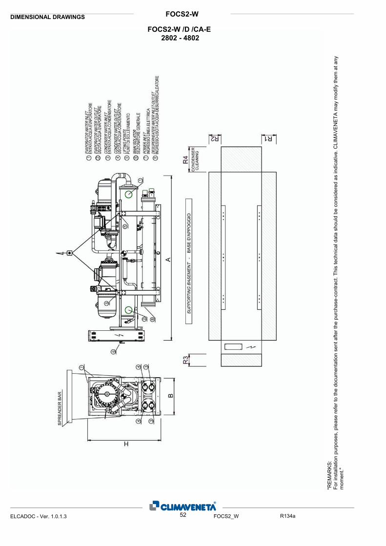
FOCS2-WDIMENSIONAL DRAWINGS
"RE
MA
RK
S:Fo
r ins
talla
tion
purp
oses
, ple
ase
refe
r to
the
docu
men
tatio
n se
nt a
fter t
he p
urch
ase-
cont
ract
. Thi
s te
chni
cal d
ata
shou
ld b
e co
nsid
ered
as
indi
cativ
e. C
LIM
AV
EN
ETA
may
mod
ify th
em a
t any
m
omen
t."
52ELCADOC - Ver. 1.0.1.3 FOCS2_W R134a
FOCS2-W /D /CA-E 2802 - 4802

FOCS2-WDIMENSIONAL DRAWINGS
ØIN/OUT
ØIN/OUTIN/OUTR4
[mm]
R3
[mm]
R2
[mm]
R1
[mm]
PESO
[kg]
H
[mm]
B
[mm]
A
[mm]
SIZE DIMENSIONS AND WE CLEARANCEPLANT SIDE HEAT
EXCHANGER
ØTYPE TYPE TYPE
SOURCE SIDE HEAT
EXCHANGER
AUXILIARY SIDE HEAT
EXCHANGER
4600 1150 2195 5390 900 900 1500 3000 FLEXIBLE JOINT 8" FLEXIBLE JOINT 5" GAS 1"1/4FOCS2-W /D /CA-E 28024950 1150 2195 6470 900 900 1500 2750 FLEXIBLE JOINT 8" FLEXIBLE JOINT 5" GAS 1"1/4FOCS2-W /D /CA-E 32025220 1150 2195 6930 900 900 1500 2750 FLEXIBLE JOINT 8" FLEXIBLE JOINT 5" GAS 1"1/4FOCS2-W /D /CA-E 36024920 1285 2430 8500 900 900 1500 2750 FLEXIBLE JOINT 10" FLEXIBLE JOINT 5" GAS 1"1/4FOCS2-W /D /CA-E 42024920 1285 2430 8530 900 900 1500 2750 FLEXIBLE JOINT 10" FLEXIBLE JOINT 5" GAS 1"1/4FOCS2-W /D /CA-E 4802
53ELCADOC - Ver. 1.0.1.3 FOCS2_W R134a

FOCS2-WDIMENSIONAL DRAWINGS
"RE
MA
RK
S:Fo
r ins
talla
tion
purp
oses
, ple
ase
refe
r to
the
docu
men
tatio
n se
nt a
fter t
he p
urch
ase-
cont
ract
. Thi
s te
chni
cal d
ata
shou
ld b
e co
nsid
ered
as
indi
cativ
e. C
LIM
AV
EN
ETA
may
mod
ify th
em a
t any
m
omen
t."
54ELCADOC - Ver. 1.0.1.3 FOCS2_W R134a
FOCS2-W /R /CA-E 1301 - 1801

FOCS2-WDIMENSIONAL DRAWINGS
ØIN/OUT
ØIN/OUTIN/OUTR4
[mm]
R3
[mm]
R2
[mm]
R1
[mm]
PESO
[kg]
H
[mm]
B
[mm]
A
[mm]
SIZE DIMENSIONS AND WE CLEARANCEPLANT SIDE HEAT
EXCHANGER
ØTYPE TYPE TYPE
SOURCE SIDE HEAT
EXCHANGER
AUXILIARY SIDE HEAT
EXCHANGER
4000 900 2000 3170 900 900 1500 3250 FLEXIBLE JOINT 5" FLEXIBLE JOINT 5" FLEXIBLE JOINT 5"FOCS2-W /R /CA-E 13014000 900 2000 3240 900 900 1500 3250 FLEXIBLE JOINT 5" FLEXIBLE JOINT 5" FLEXIBLE JOINT 5"FOCS2-W /R /CA-E 14014000 900 2100 4070 900 900 1500 3250 FLEXIBLE JOINT 6" FLEXIBLE JOINT 5" FLEXIBLE JOINT 5"FOCS2-W /R /CA-E 16014000 900 2100 4240 900 900 1500 3500 FLEXIBLE JOINT 6" FLEXIBLE JOINT 5" FLEXIBLE JOINT 5"FOCS2-W /R /CA-E 1801
55ELCADOC - Ver. 1.0.1.3 FOCS2_W R134a

FOCS2-WDIMENSIONAL DRAWINGS
"RE
MA
RK
S:Fo
r ins
talla
tion
purp
oses
, ple
ase
refe
r to
the
docu
men
tatio
n se
nt a
fter t
he p
urch
ase-
cont
ract
. Thi
s te
chni
cal d
ata
shou
ld b
e co
nsid
ered
as
indi
cativ
e. C
LIM
AV
EN
ETA
may
mod
ify th
em a
t any
m
omen
t."
56ELCADOC - Ver. 1.0.1.3 FOCS2_W R134a
FOCS2-W /R /CA-E 2802 - 3602
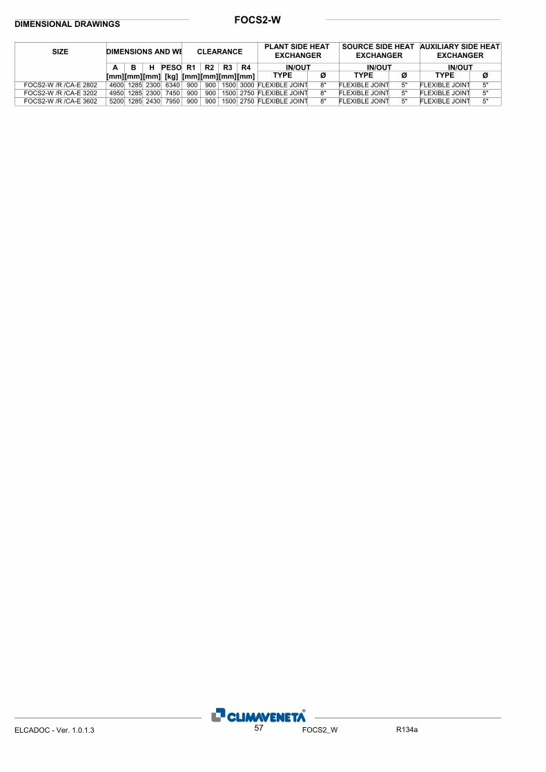
FOCS2-WDIMENSIONAL DRAWINGS
ØIN/OUT
ØIN/OUTIN/OUTR4
[mm]
R3
[mm]
R2
[mm]
R1
[mm]
PESO
[kg]
H
[mm]
B
[mm]
A
[mm]
SIZE DIMENSIONS AND WE CLEARANCEPLANT SIDE HEAT
EXCHANGER
ØTYPE TYPE TYPE
SOURCE SIDE HEAT
EXCHANGER
AUXILIARY SIDE HEAT
EXCHANGER
4600 1285 2300 6340 900 900 1500 3000 FLEXIBLE JOINT 8" FLEXIBLE JOINT 5" FLEXIBLE JOINT 5"FOCS2-W /R /CA-E 28024950 1285 2300 7450 900 900 1500 2750 FLEXIBLE JOINT 8" FLEXIBLE JOINT 5" FLEXIBLE JOINT 5"FOCS2-W /R /CA-E 32025200 1285 2430 7950 900 900 1500 2750 FLEXIBLE JOINT 8" FLEXIBLE JOINT 5" FLEXIBLE JOINT 5"FOCS2-W /R /CA-E 3602
57ELCADOC - Ver. 1.0.1.3 FOCS2_W R134a

FOCS2-WDIMENSIONAL DRAWINGS
"RE
MA
RK
S:Fo
r ins
talla
tion
purp
oses
, ple
ase
refe
r to
the
docu
men
tatio
n se
nt a
fter t
he p
urch
ase-
cont
ract
. Thi
s te
chni
cal d
ata
shou
ld b
e co
nsid
ered
as
indi
cativ
e. C
LIM
AV
EN
ETA
may
mod
ify th
em a
t any
m
omen
t."
58ELCADOC - Ver. 1.0.1.3 FOCS2_W R134a
FOCS2-W /CA-E FOCS2-W /H /CA-E
5402 - 6002
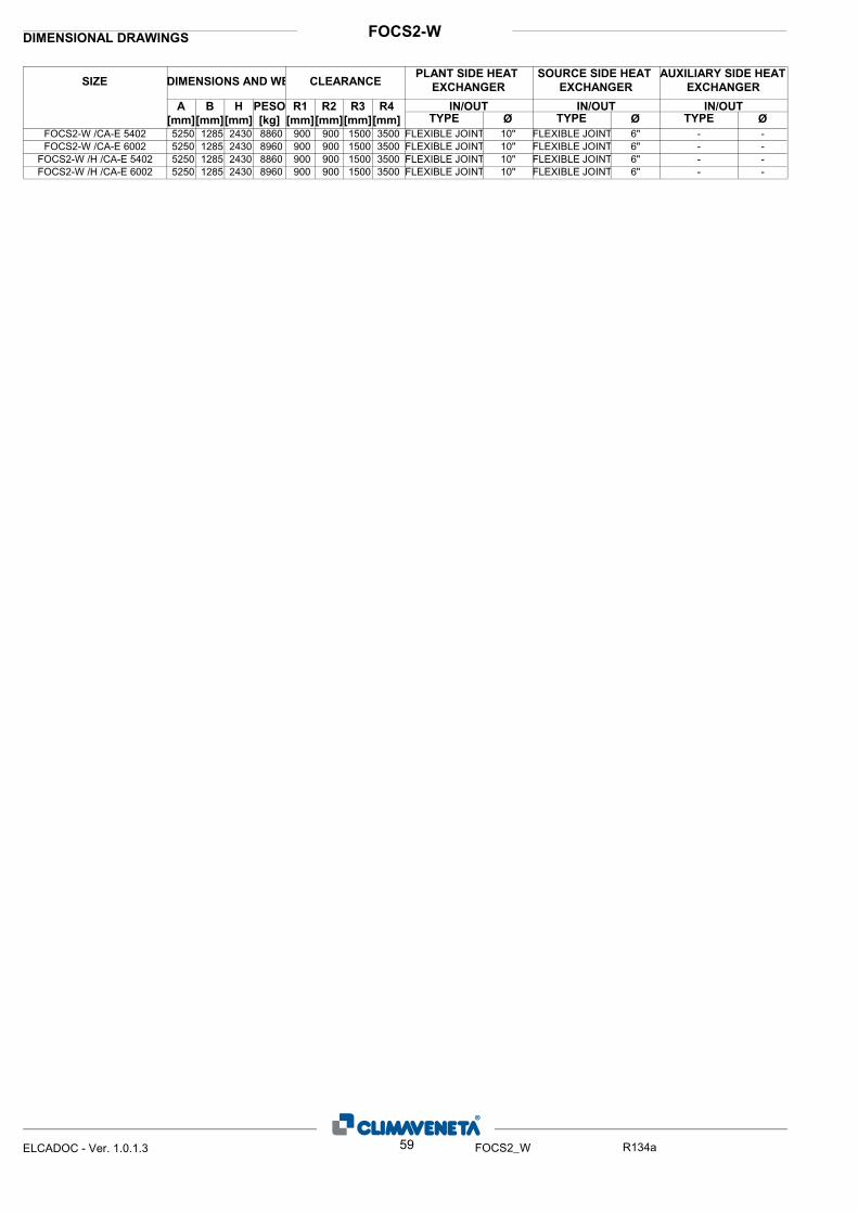
FOCS2-WDIMENSIONAL DRAWINGS
ØIN/OUT
ØIN/OUTIN/OUTR4
[mm]
R3
[mm]
R2
[mm]
R1
[mm]
PESO
[kg]
H
[mm]
B
[mm]
A
[mm]
SIZE DIMENSIONS AND WE CLEARANCEPLANT SIDE HEAT
EXCHANGER
ØTYPE TYPE TYPE
SOURCE SIDE HEAT
EXCHANGER
AUXILIARY SIDE HEAT
EXCHANGER
5250 1285 2430 8860 900 900 1500 3500 FLEXIBLE JOINT 10" FLEXIBLE JOINT 6" - -FOCS2-W /CA-E 54025250 1285 2430 8960 900 900 1500 3500 FLEXIBLE JOINT 10" FLEXIBLE JOINT 6" - -FOCS2-W /CA-E 60025250 1285 2430 8860 900 900 1500 3500 FLEXIBLE JOINT 10" FLEXIBLE JOINT 6" - -FOCS2-W /H /CA-E 54025250 1285 2430 8960 900 900 1500 3500 FLEXIBLE JOINT 10" FLEXIBLE JOINT 6" - -FOCS2-W /H /CA-E 6002
59ELCADOC - Ver. 1.0.1.3 FOCS2_W R134a
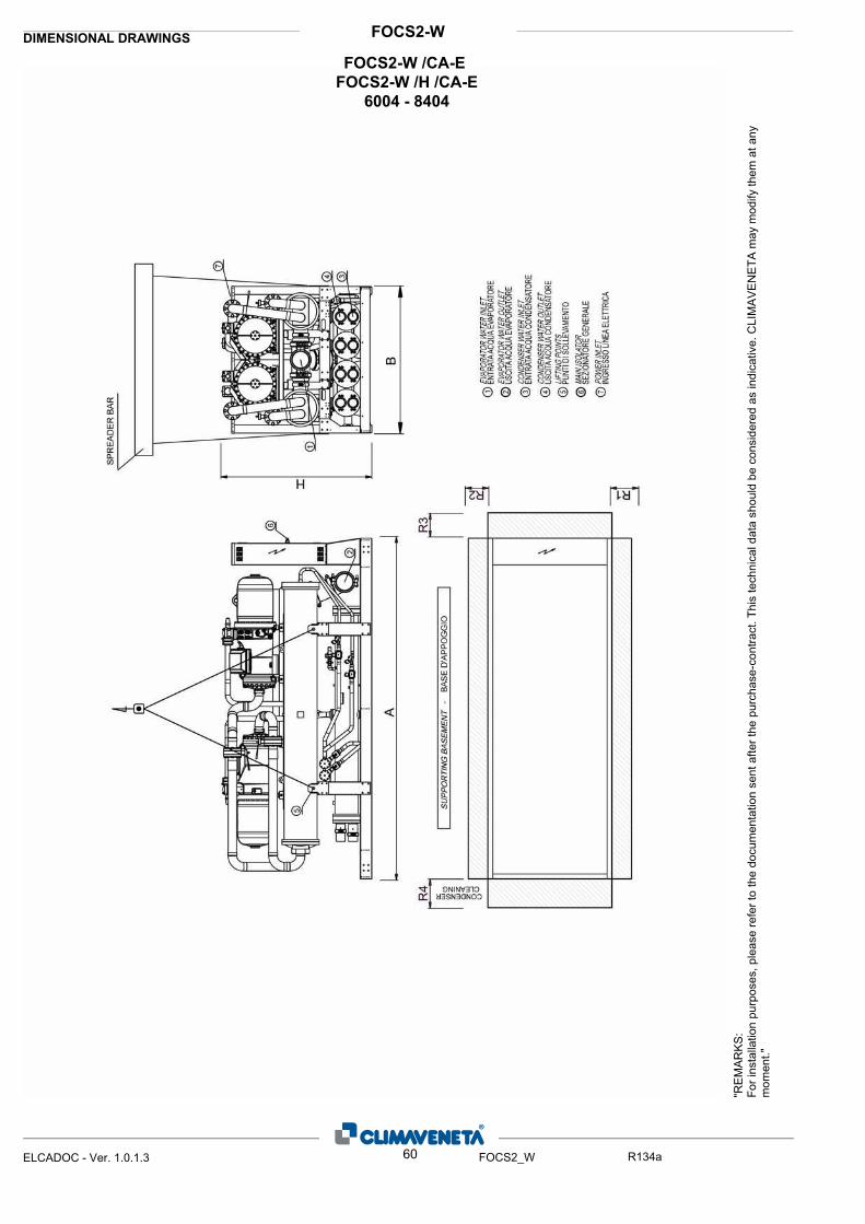
FOCS2-WDIMENSIONAL DRAWINGS
"RE
MA
RK
S:Fo
r ins
talla
tion
purp
oses
, ple
ase
refe
r to
the
docu
men
tatio
n se
nt a
fter t
he p
urch
ase-
cont
ract
. Thi
s te
chni
cal d
ata
shou
ld b
e co
nsid
ered
as
indi
cativ
e. C
LIM
AV
EN
ETA
may
mod
ify th
em a
t any
m
omen
t."
60ELCADOC - Ver. 1.0.1.3 FOCS2_W R134a
FOCS2-W /CA-E FOCS2-W /H /CA-E
6004 - 8404

FOCS2-WDIMENSIONAL DRAWINGS
ØIN/OUT
ØIN/OUTIN/OUTR4
[mm]
R3
[mm]
R2
[mm]
R1
[mm]
PESO
[kg]
H
[mm]
B
[mm]
A
[mm]
SIZE DIMENSIONS AND WE CLEARANCEPLANT SIDE HEAT
EXCHANGER
ØTYPE TYPE TYPE
SOURCE SIDE HEAT
EXCHANGER
AUXILIARY SIDE HEAT
EXCHANGER
5000 2250 2305 12350 900 900 1500 3500 FLEXIBLE JOINT 10" FLEXIBLE JOINT 5" - -FOCS2-W /CA-E 60045000 2250 2305 13300 900 900 1500 3500 FLEXIBLE JOINT 10" FLEXIBLE JOINT 5" - -FOCS2-W /CA-E 64045300 2250 2305 13900 900 900 1500 3500 FLEXIBLE JOINT 10" FLEXIBLE JOINT 5" - -FOCS2-W /CA-E 68045300 2250 2305 14000 900 900 1500 3500 FLEXIBLE JOINT 10" FLEXIBLE JOINT 5" - -FOCS2-W /CA-E 72045100 2250 2455 15620 900 900 1500 3500 FLEXIBLE JOINT 10" FLEXIBLE JOINT 5" - -FOCS2-W /CA-E 78045100 2250 2455 15800 900 900 1500 3000 FLEXIBLE JOINT 10" FLEXIBLE JOINT 5" - -FOCS2-W /CA-E 84045000 2250 2305 12350 900 900 1500 3500 FLEXIBLE JOINT 10" FLEXIBLE JOINT 5" - -FOCS2-W /H /CA-E 60045000 2250 2305 13300 900 900 1500 3500 FLEXIBLE JOINT 10" FLEXIBLE JOINT 5" - -FOCS2-W /H /CA-E 64045300 2250 2305 13900 900 900 1500 3500 FLEXIBLE JOINT 10" FLEXIBLE JOINT 5" - -FOCS2-W /H /CA-E 68045300 2250 2305 14000 900 900 1500 3500 FLEXIBLE JOINT 10" FLEXIBLE JOINT 5" - -FOCS2-W /H /CA-E 72045100 2250 2455 15620 900 900 1500 3500 FLEXIBLE JOINT 10" FLEXIBLE JOINT 5" - -FOCS2-W /H /CA-E 78045100 2250 2455 15800 900 900 1500 3000 FLEXIBLE JOINT 10" FLEXIBLE JOINT 5" - -FOCS2-W /H /CA-E 8404
61ELCADOC - Ver. 1.0.1.3 FOCS2_W R134a
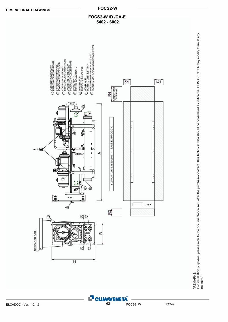
FOCS2-WDIMENSIONAL DRAWINGS
"RE
MA
RK
S:Fo
r ins
talla
tion
purp
oses
, ple
ase
refe
r to
the
docu
men
tatio
n se
nt a
fter t
he p
urch
ase-
cont
ract
. Thi
s te
chni
cal d
ata
shou
ld b
e co
nsid
ered
as
indi
cativ
e. C
LIM
AV
EN
ETA
may
mod
ify th
em a
t any
m
omen
t."
62ELCADOC - Ver. 1.0.1.3 FOCS2_W R134a
FOCS2-W /D /CA-E 5402 - 6002
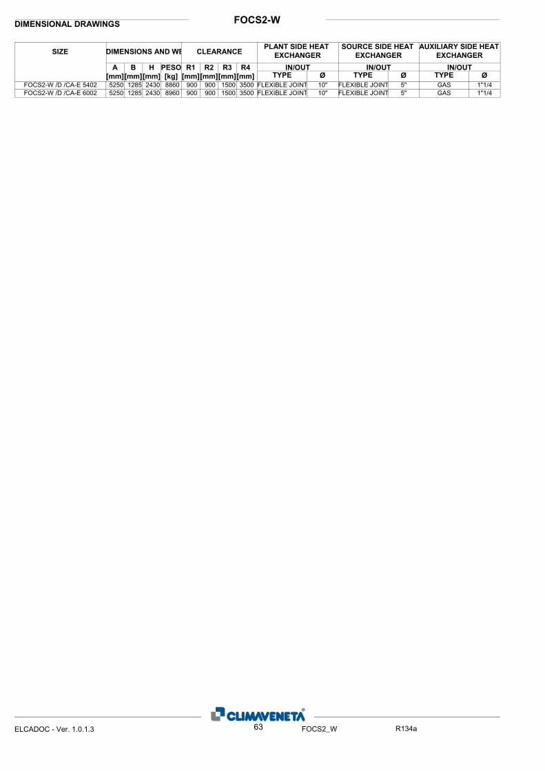
FOCS2-WDIMENSIONAL DRAWINGS
ØIN/OUT
ØIN/OUTIN/OUTR4
[mm]
R3
[mm]
R2
[mm]
R1
[mm]
PESO
[kg]
H
[mm]
B
[mm]
A
[mm]
SIZE DIMENSIONS AND WE CLEARANCEPLANT SIDE HEAT
EXCHANGER
ØTYPE TYPE TYPE
SOURCE SIDE HEAT
EXCHANGER
AUXILIARY SIDE HEAT
EXCHANGER
5250 1285 2430 8860 900 900 1500 3500 FLEXIBLE JOINT 10" FLEXIBLE JOINT 5" GAS 1"1/4FOCS2-W /D /CA-E 54025250 1285 2430 8960 900 900 1500 3500 FLEXIBLE JOINT 10" FLEXIBLE JOINT 5" GAS 1"1/4FOCS2-W /D /CA-E 6002
63ELCADOC - Ver. 1.0.1.3 FOCS2_W R134a

FOCS2-WDIMENSIONAL DRAWINGS
"RE
MA
RK
S:Fo
r ins
talla
tion
purp
oses
, ple
ase
refe
r to
the
docu
men
tatio
n se
nt a
fter t
he p
urch
ase-
cont
ract
. Thi
s te
chni
cal d
ata
shou
ld b
e co
nsid
ered
as
indi
cativ
e. C
LIM
AV
EN
ETA
may
mod
ify th
em a
t any
m
omen
t."
64ELCADOC - Ver. 1.0.1.3 FOCS2_W R134a
FOCS2-W /D /CA-E 6004 - 7204
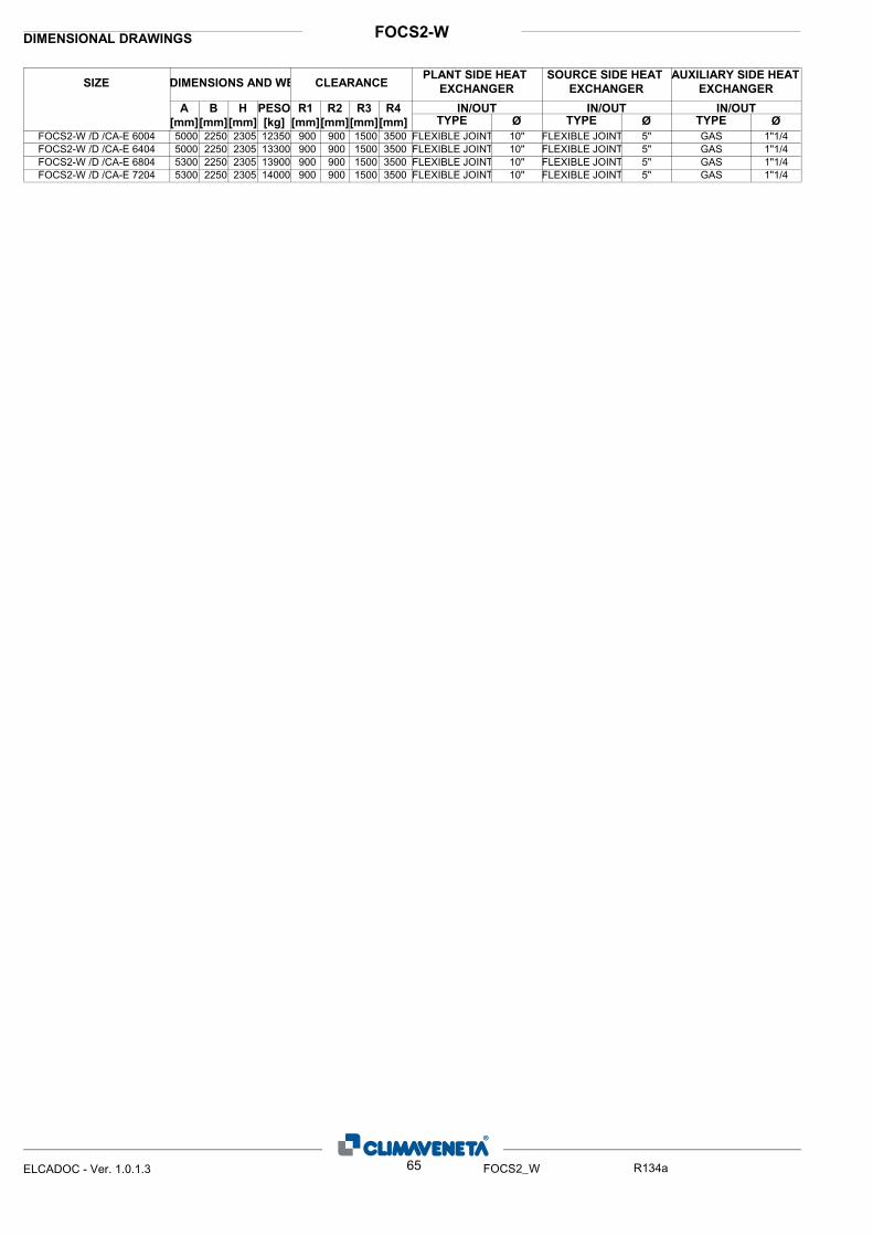
FOCS2-WDIMENSIONAL DRAWINGS
ØIN/OUT
ØIN/OUTIN/OUTR4
[mm]
R3
[mm]
R2
[mm]
R1
[mm]
PESO
[kg]
H
[mm]
B
[mm]
A
[mm]
SIZE DIMENSIONS AND WE CLEARANCEPLANT SIDE HEAT
EXCHANGER
ØTYPE TYPE TYPE
SOURCE SIDE HEAT
EXCHANGER
AUXILIARY SIDE HEAT
EXCHANGER
5000 2250 2305 12350 900 900 1500 3500 FLEXIBLE JOINT 10" FLEXIBLE JOINT 5" GAS 1"1/4FOCS2-W /D /CA-E 60045000 2250 2305 13300 900 900 1500 3500 FLEXIBLE JOINT 10" FLEXIBLE JOINT 5" GAS 1"1/4FOCS2-W /D /CA-E 64045300 2250 2305 13900 900 900 1500 3500 FLEXIBLE JOINT 10" FLEXIBLE JOINT 5" GAS 1"1/4FOCS2-W /D /CA-E 68045300 2250 2305 14000 900 900 1500 3500 FLEXIBLE JOINT 10" FLEXIBLE JOINT 5" GAS 1"1/4FOCS2-W /D /CA-E 7204
65ELCADOC - Ver. 1.0.1.3 FOCS2_W R134a
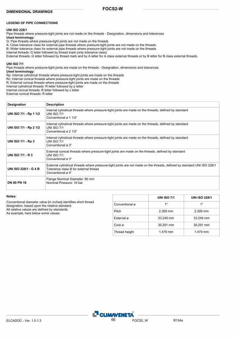
LEGEND OF PIPE CONNECTIONS
DIMENSIONAL DRAWINGSFOCS2-W
UNI ISO 228/1
Pipe threads where pressure-tight joints are not made on the threads - Designation, dimensions and tolerancesUsed terminology:
G: Pipe threads where pressure-tight joints are not made on the threadsA: Close tolerance class for external pipe threads where pressure-tight joints are not made on the threadsB: Wider tolerance class for external pipe threads where pressure-tight joints are not made on the threads Internal threads: G letter followed by thread mark (only tolerance class)External threads: G letter followed by thread mark and by A letter for A class external threads or by B letter for B class external threads.
UNI ISO 7/1
Pipe threads where pressure-tight joints are made on the threads - Designation, dimensions and tolerancesUsed terminology:
Rp: Internal cylindrical threads where pressure-tight joints are made on the threadsRc: Internal conical threads where pressure-tight joints are made on the threadsR: External conical threads where pressure-tight joints are made on the threadsInternal cylindrical threads: R letter followed by p letterInternal conical threads: R letter followed by c letterExternal conical threads: R letter
UNI ISO 7/1 - Rp 1 1/2
UNI ISO 7/1 - Rp 2 1/2
UNI ISO 7/1 - Rp 3
UNI ISO 228/1 - G 4 B
DN 80 PN 16
UNI ISO 7/1 - R 3
Designation Description
Internal cylindrical threads where pressure-tight joints are made on the threads, defined by standardUNI ISO 7/1Conventional ø 1 1/2”
Internal cylindrical threads where pressure-tight joints are made on the threads, defined by standardUNI ISO 7/1Conventional ø 2 1/2”
Internal cylindrical threads where pressure-tight joints are made on the threads, defined by standardUNI ISO 7/1Conventional ø 3”
External conical threads where pressure-tight joints are made on the threads, defined by standardUNI ISO 7/1Conventional ø 3”
External cylindrical threads where pressure-tight joints are not made on the threads, defined by standard UNI ISO 228/1Tolerance class B for external threadConventional ø 4”
Flange Nominal Diameter: 80 mmNominal Pressure: 16 bar
UNI ISO 7/1 UNI ISO 228/1
1"1"
2.309 mm2.309 mm
33.249 mm33.249 mm
30.291 mm30.291 mm
1.479 mm1.479 mm
Notes:
Conventional diameter value [in inches] identifies short thread designation, based upon the relative standard.All relative values are defined by standards.As example, here below some values:
Conventional ø
Pitch
External ø
Core ø
Thread height
66ELCADOC - Ver. 1.0.1.3 FOCS2_W R134a
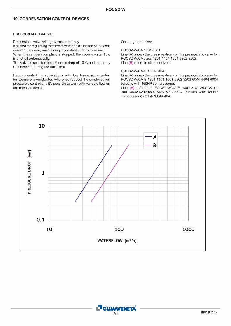
Pressostatic valve with grey cast iron body. It’s used for regulating the fl ow of water as a function of the con-densing pressure, maintaining it constant during operation.When the refrigeration plant is stopped, the cooling water fl ow is shut off automatically.The valve is selected for a thermic drop of 10°C and tested by Climaveneta during the unit’s test.
Recommended for applications with low temperature water, for example groundwater, where it’s request the condensation pressure’s control and it’s possible to work with variable fl ow on the rejection circuit.
On the graph below:
FOCS2-W/CA 1301-9604 Line (A) shows the pressure drops on the pressostatic valve for FOCS2-W/CA sizes 1301-1401-1601-2802-3202. Line (B) refers to all other sizes.
FOCS2-W/CA-E 1301-8404Line (A) shows the pressure drops on the pressostatic valve for FOCS2-W/CA-E 1301-1401-1601-2802-3202-6004-6404-6804 (circuits with 160HP compressors); Line (B) refers to FOCS2-W/CA-E 1801-2101-2401-2701-3001-3602-4202-4802-5402-6002-6804 (circuits with 180HP compressors) -7204-7804-8404;
10. CONDENSATION CONTROL DEVICES
PRESSOSTATIC VALVE
0.1
1
10
10 100 1000
Portata [m3/h]
Cadu
ta d
i pr
essioe
n [b
ar]
AB
PR
ES
SU
RE
DR
OP
[b
ar]
WATERFLOW [m3/h]
A1
FOCS2-W
HFC R134a
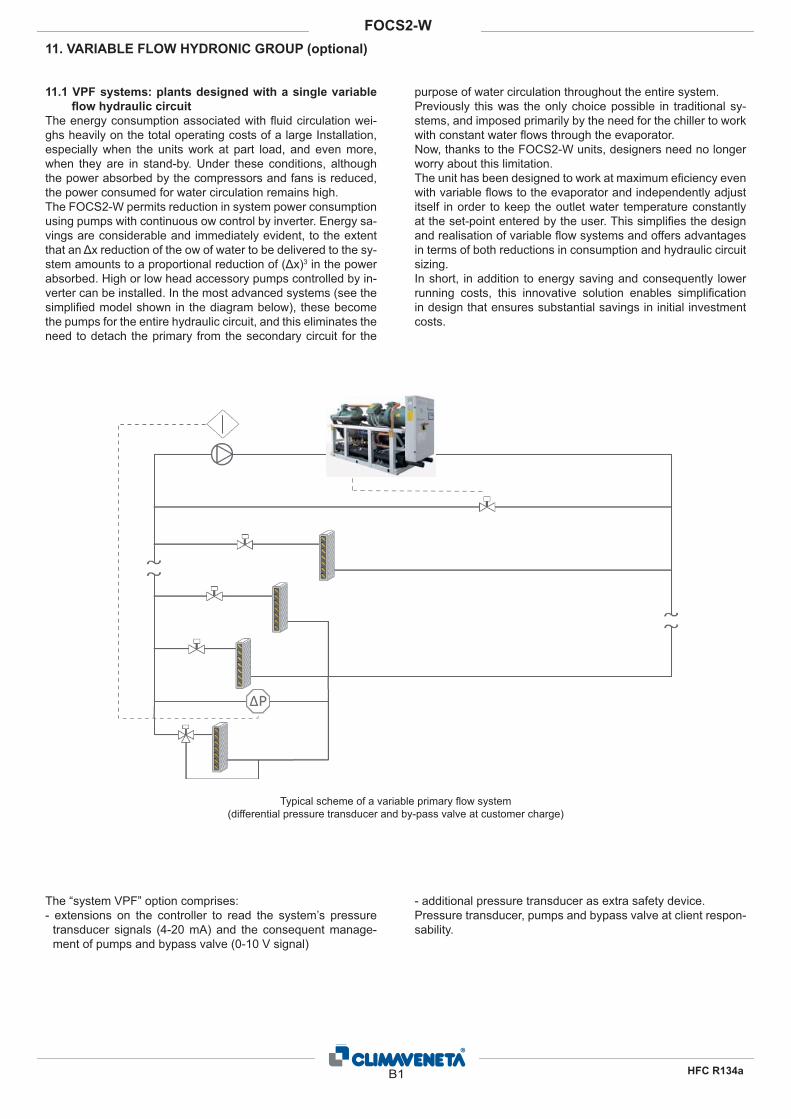
11. VARIABLE FLOW HYDRONIC GROUP (optional)
11.1 VPF systems: plants designed with a single variable
fl ow hydraulic circuit
The energy consumption associated with � uid circulation wei-ghs heavily on the total operating costs of a large Installation, especially when the units work at part load, and even more, when they are in stand-by. Under these conditions, although the power absorbed by the compressors and fans is reduced, the power consumed for water circulation remains high.The FOCS2-W permits reduction in system power consumption using pumps with continuous ow control by inverter. Energy sa-vings are considerable and immediately evident, to the extent that an Δx reduction of the ow of water to be delivered to the sy-stem amounts to a proportional reduction of (Δx)3 in the power absorbed. High or low head accessory pumps controlled by in-verter can be installed. In the most advanced systems (see the simpli� ed model shown in the diagram below), these become the pumps for the entire hydraulic circuit, and this eliminates the need to detach the primary from the secondary circuit for the
purpose of water circulation throughout the entire system. Previously this was the only choice possible in traditional sy-stems, and imposed primarily by the need for the chiller to work with constant water � ows through the evaporator. Now, thanks to the FOCS2-W units, designers need no longer worry about this limitation. The unit has been designed to work at maximum e� ciency even with variable � ows to the evaporator and independently adjust itself in order to keep the outlet water temperature constantly at the set-point entered by the user. This simpli� es the design and realisation of variable � ow systems and offers advantages in terms of both reductions in consumption and hydraulic circuit sizing. In short, in addition to energy saving and consequently lower running costs, this innovative solution enables simpli� cation in design that ensures substantial savings in initial investment costs.
The “system VPF” option comprises: - extensions on the controller to read the system’s pressure
transducer signals (4-20 mA) and the consequent manage-ment of pumps and bypass valve (0-10 V signal)
- additional pressure transducer as extra safety device.Pressure transducer, pumps and bypass valve at client respon-sability.
Typical scheme of a variable primary � ow system (differential pressure transducer and by-pass valve at customer charge)
B1
FOCS2-W
HFC R134a

Working logic of “smart” plant with an only one variable primary fl ow circuit
Traditional plant “Smart” plant
It is necessary to have a “decuple” system, which uses constant water � ow through each chiller evaporator and variable water � ow through each cooling coil to satisfy space loads. As each two-way valve adjusts the ow of chilled water through the coil to satisfy the existing load, the distribution pump responds by regulating the amount of chilled water delivered. Water � ows through the bypass in either direction as needed to balance the system.
There is an only one variable primary � ow circuit, which vari-es water � ow throughout the entire system – that is, through the evaporator of the operating chiller as well as through the cooling coils. Two-way control valves and a bypass valve are required; the bypass valve ensures that the amount of the � ow that returns to the operating chiller(s) never falls below the mi-nimum limit.
Situation 1. 100% cooling capacity
�p�p
Pf=730 kW
3/h
Q=31.5 m3/h
Q=94.5 m3/h
7°C
7°C
12°C
Q=0 m
�p�p
Pf=730 kW
Q=0 m3/h
Q=31.5 m3/h
Q=94.5 m3/h
7°C
7°C12°C
12°CQ=126 m3/h
chiusa
VARIABLE FLOW HYDRONIC GROUP (optional)
B2
FOCS2-W
HFC R134a
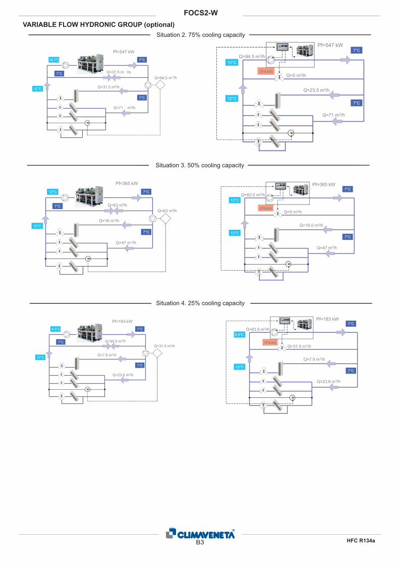
Situation 2. 75% cooling capacity
Situation 3. 50% cooling capacity
Situation 4. 25% cooling capacity
�p�p
Pf=547 kW
3/h
Q=31.5 m3/h
Q=71 m3/h
7°C
7°C
10.7°C
Q=31.5 m7°C3/hQ=94.5 m
12°C
�p�p
Pf=547 kW
Q=0 m3/h
Q=23.5 m3/h
Q=71 m3/h
7°C
7°C12°C
12°CQ=94.5 m3/h
chiusa
�p�p
Pf=365 kW
3/h
Q=16 m3/h
Q=47 m 3/h
7°C
7°C
12°C
Q=63 m
12°C
7°C3/hQ=63 m
�p�p
Pf=365 kW
Q=0 m3/h
Q=16.0 m3/h
Q=47 m3/h
7°C
7°C12°C
12°CQ=63.0 m3/h
chiusa
�p�p
Pf=183 kW
3/h
Q=7.9 m3/h
Q=23.6 m3/h
7°C
7°C
8.3°C
Q=94.5 m7°C
12°C
Q=31.5 m3/h
�p�p
Pf=183 kW
Q=31.5 m3/h
Q=7.9 m3/h
Q=23.6 m3/h
7°C
7°C12°C
9.5°CQ=63.0 m3/h
chiusa
VARIABLE FLOW HYDRONIC GROUP (optional)
B3
FOCS2-W
HFC R134a

VARIABLE FLOW HYDRONIC GROUP (optional)
11.2 VPF.D systems: plants designed for variable fl ow, de-
coupled, primary and secondary circuits
Even in that cases in which is not possible to work with a sin-gle variable primary � ow circuit, or in that situations in which is preferible to mantain decoupled the primary circuit (to the units) and the secondary circuit (to the plants), it’s possible the prima-ry � ow on pumps controlled by the unit.The energy savings are lower than the solution with a unique VPF system, but still important expecially when the units are in stand-by where it’s possible to reduce the water� ow through the unit up to 50%.The VPF.D systems can be easily adopted in retro� t applica-tion, where the chiller is supposed to be replaced but the plant isn’t.
The regulation is up to the unit’s controller, detecting the delta temperature at the primary heat exchanger: when the building’s load decreases, water� ow is reduced in order to mantain a � -xed delta T between the exchanger’s inlet and outlet. The VPF.D system by Climaveneta assures even the water� ow balancing between primary and secondary circuit, in order to avoid the � ow inversion in the decoupling pipe.
Typical scheme of a system with decoupled variable � ow primary and secondary circuits [Temperature probes separately supplied]
Decoupling pipe
B4
FOCS2-W
HFC R134a

VARIABLE FLOW HYDRONIC GROUP (optional)
11.3 For VPF system: indications for the bypass pipe si-
zing
Differential pressure transducer on the farest pipe of the plant and by-pass valve are at customer charge. Climaveneta provides only some indications for the plants de-sign, as a function of the minimum water� ow on the primary heat exchanger.
11.4 For VPF.D system: indications for the decoupling pipe
sizing
Climaveneta provides in the table below some indications for the plants design, as a function of the nominal water� ow on the primary heat exchanger.NOTE: temperature probes are separately supplied
Minimum waterfl ow
to technical bulletin
[m3/h]
Kvs Recommended valve ��Valve Valve motor ��ByPass
Da 19 a 30 40 VVG41.50 DN50 SKB60 DN50 (2”)� no a 37 49 VVF31.65 DN65 SKB60 DN65 (2"½)� no a 60 78 VVF31.80 DN80 SKB60 DN80 (3“)� no a 95 124 VVF31.90 DN100 SKC60 DN100 (4“)� no a 150 200 VVF31.91 DN125 SKC60 DN125 (5“)� no a 230 300 VVF31.92 DN150 SKC60 DN150 (6”)
2-way valve and minimum recommended bypass pipe diameter as a function of the minimum water� ow.
Minimum waterfl ow to
technical bulletin
[m3/h]
��Decoupling pipe
Da 25 a 40 2"½� no a 60 3"� no a 100 4"� no a 150 5"� no a 225 6"� no a 375 8"
Minimum decoupling pipe diameter as a function of the minimum water� ow
B5
FOCS2-W
HFC R134a