Embed Size (px)
Citation preview

JULY, 1957
RADII
TELEISION (
ELECR0NIC
THE TECHNICAL JOURNAL OF THE TELEVISION -RADIO TRADE
-1 VERTICAL !RETRIPLATECE
3CS6 SYNC SEP and NOISE
HOR FRED COIL á
HOR - AFC DISCR
GATE
C lode -coupled horizontal mulfivbrafor and del -Triode vertical deflection circuitry of 21nch TV chassis using 110° picture tube. See circuit analysis, this issue
.
II II II 1I
II
VERT HOLD .ñ
I2DQ6A -L HOR OUTPUT
THERMISTOR
VERT LIN IB3GT
H V RECT
THERMISTOR
41-1 HEIGHT
I2AX4GT DAMPER
-,6110
45-92-9 S 092
'kVOOS *S11VA Xf101S Al-wV'O13m V1S 010V8 -S 3)108.4 3 811531
Ir
.1/?.

depend on
RADIART VI RATORS
Radiart vibrators are the
Standard of Comparison for
quality, performance and
dependability in the industry!
Men who know ...manage.
ment, jobbers .... and
servicemen ... ALL agree
that experience over the
years has dictated that
RADIART vibrators are the
ones to buy and use.
AND ... the complete line
of COMMUNICATION
vibrators offers the correct
replacement for 6 volt
and 12 volt applications.
Be sure you have the new
vibrator replacement guide...
write for your FREE copy...
THE RADIART CORP.
<Id>
CLEVELAN D
...the COMPLETE replacement line / 13, OHIO
A Subsidiary of Cornell-Dubilier

Successful Electronics Training
technical training PLUS
Commercial FCC License
PLUS Cleveland Institute
Diploma
ó
EQUAL= .0P
i
greater income for. you
Cleveland Institute
Diploma
Accredited by National Home Study Council
Cleveland Institute of Radio Electronics
Desk S-7, 4900 Euclid Bldg. Cleveland 3, Ohio
0 -
How to increase your income
Two-way radio Microwave relay Home electronics Industrial electronics Radar
Find out how you can increase your monthly income by installing and maintaining the types of electronic devices listed above.
Anyone now in the radio -television servicing field can qualify. A Commercial FCC license will open the door to new profit areas ... and the work is interesting.
Don't limit yourself to receiver servicing. Prepare your- self to handle the more profitable jobs in electronics. Fill out the coupon below and mail it TODAY. The information is free!
MAIL COUPON TODAY
I Cleveland Institute of Radio Electronics MM IMM
Desk 5-7, 4900 Euclid Bldg., Cleveland 3, Ohio
1 Please send Free Booklets prepared to help me get ahead in Electronics. IP) I have had training or experience in Electronics as indicated below:
Military Amateur Radio nx Telephone Company Radio -TV Servicing Broadcasting Manufacturing Home Experimenting
U Other ...
IIn what kind of work are you now engaged?. In what branch of Electronics are you interested'
Name Age Address
' City .......... Zone State No Salesman will call
MN NW MN - - ~I NM MI
SERVICE, JULY, 1957 I

IlI ? f - ;5), ...1°'
M 1
it1°
E
111.1101
.
F RAC
Dealer Net 16 oz. can
The finest acrylic spray you can buy- made by the. greatest name. in spray paints ...Plastic Kote. _
Now sold to the radió technician .by the maker's of the famous "Tube Caddy." Ask.your distributor. . 'Reg. TM
TZ PRODUCTS il= COMPANY
310 MAIN STREET GENOA, ILLINOIS
a.tube caddy for every purpose
ti tube caddy
IJ
the JUNIOR $9,50 Dlr. Net. Ideal for quick trips. 153/ x -121/2 x 8 in. Model. TC-2A
the CARRY -ALL $14.50 Dlr. Net. Takes tubes, tools, meter. 21 x 15
x 8in: Model TC-4
the ORIGINAL $14'.50 Dlr. Net. Favorite of thousands. Upright de- sign. 21 x 15 x 8 in. Model TC-1C
`Reg. TM of Argos.Product.s Co., originators and leading manufacturers of. tube cases for the electronic technician.'
PRODUCTS COMPANY
310 MAIN STREET GENOA, ILLINOIS
2 SERVICE, JULY, 1957
Vol. 26 No. 7
11111111111111111111:1111111111111
261h YEAR OF
CONTINUOUS PUBLICATION
JULY, 1957
THE TECHNICAL JOURNAL OF THE TELEVISION -RADIO TRADE Including RADIO MERCHANDISING and TELEVISION MERCHANDISING
Registered U. S. Patent Office
11111111111111111WI IIIPPPIIn
COVER CIRCUIT
110° 21 -Inch Horizontal-Veriical Deflection Circuitry (Sylvania Si lo)
FEATURES
This Month in SERVICE 7
Fixed -Frequency Low -Band FM Mobile Receiver (With Complete Circuit) Warren M. Seeley 8
21 -Inch TV Chassis Using 110° Picture Tube (Front Cover; With Complete Circuit) Don Winters 10
Servicing Transistor Radios (Service Notes) 14
Marine -Mobile Radio Installation -Servicing in San Pedro, Calif. (Service Engineering) 15
TV -Antenna Replacement Field -Investigation Report (Tv Antenna Digest) 16
B-W/Color-TV VHF Tuner Mixers -Oscillators Wayne S. Rial 19
Alignment of TV Chassis Using Marker -Adder Techniques... Rhys Samuel 20
Audio: Outdoor Amplifiers for Commercial Sound... Norman Crowhurst 26
Audio: Changing Needles in Phonos ... Mechanical -Feedback Vibration - Distortion Cures . . . Crystal -Ceramic Pickup Replacement With Magnetic Types
CIRCUIT DIAGRAMS
36
Seeley 30-50 Mc FM Chassis (Complete Basic Colpitts, Ultraudion and Push -Pull Circuit) 9 Oscillator Circuits 19
Sylvania S110 2l -Inch Set (Complete Tuner Coupling Circuits 19 Circuit) 11 Alignment Test Setups 20
Picture -Tube Flux -Cancellation Schematic. 12 RCA WR-70A Marker -Adder (Complete TV -Horizontal Output Showing Current Circuit) 21
Flow 12 RF-IF Alignment Setup With Marker -Adder 24 Sylvania 5110 Vertical Scan 12 Output Transformer Tapping 26 RCA 8-9 BT -9 Con-IF-Det Transistor Stages 14 Twin -T -Feedback Slot Amplifier Circuit 26
DEPARTMENTS
Transistor -Radio Service Notes 14 Catalogs and Books 28 Service Engineering 15 Radio -TV Components ... Accessories.... 29 TV Antenna Digest 16 Test Instruments 30 Association News 25 Bench -Field Tools 31 Ten Years Ago in SERVICF 25 Audio Installation and Service 36 Audio Developments 26, 36, 37 Personnel 40
Index to Advertisers 39
Entire Contents Copyright 1957, Bryan Davis Publishing Co., Inc.
Second -Class mail privileges authorized at New York, N. Y.; additional entry at the Post Office, Norwalk, Conn. . . . Subscription price: $2.00 per year ($5.00 for 3 years) in the U.S.A. and Canada; 25 cents per copy. $3.00 per year in foreign countries; 35 cents per copy.

,1L D
j ,, ,, I .,..ABC gIIIIY 'a,m,mnmam I
COLA.'
EDITOR and PUBLICATION DIRECTOR
Lewis Winner
Associate Editor:
Assistant Editor:
Editorial Assistant:
Editorial Assistant:
Art Director:
Supervisor, Circuit
Editorial Production
David E. Pearsall II
Robert D.Wengenroth
Arnold Gewirtz
Howard Jennings
Anthony R. Ali
Diagrams: Michael D. Bellezza
: Astrid Kelly
e
CIRCULATION DEPARTMENT
Circulation Manager: A. Gcebel
Ass't Circulation Mgr.: A. Kiernan
a
ADVERTISING DEPARTMENT
Advertising Mgr.: Aaron L. Lafer
Pacific Coast: Leo Sands. Dist. Mgr. 535 Ramona St.
Palo Alto, Calif.: Tel.: DAvenport 5-3716
Published Monthly by Bryan Davis Publishing Company, Inc. 52 Vanderbilt Ave., New York 17, N. Y.
Tel.: MUrray Hill 0-0170
B. S. Davis, Pres. Lewis Winner, Vice-Pres.
It's a sure thing ...the odds are 4 to 1
in. your favor! ..f
4' ár'n
11Z3yy J .+, l 1n
-
r
'`^c1, F°fh A
^`.^BGYrj, pay--O .
**** ,/a od%c/ °Os
Bata.
l
ut your mo " y...
Wirwóusi o of
1'1 _
.
:.
Ce trálab ;
Stable mates in Centralab's long line of champions- Model WW and WN Wirewounds pack a 5 -watt con- trol into a 2 -watt size, in short- or long -shaft styles. Now, one size takes care of 2-, 3-, 4-, and 5 -watt re- placements in TV, hi-fi, home and auto radio sets.
Every Centralab Wirewound is a real thorough- bred - and gives you a winning ticket that cuts in- ventory, helps save time, helps you make more money.
Here's another sure thing - Centralab Wire - wounds are favorites in the rich industrial handicap.
Ask your Centralab distributor about these versa- tile controls. Complete information on these and other top-quality Centralab components can be found in Centralab's new catalog 30.
B1559 abO A DIVISION OF GLOBE -UNION INC.
© 934G EAST KEEFE AVENUE MILWAUKEE I, WISCONSIN
SERVICE, JULY, 1957 3

Using a special v -h -f tuner, a General Electric applica- tions engineer double- checks a G -E r -f -amplifier tube for low noise level ... meaning sharp, virtually snow -free TV pictures, even in weak signal areas.
7
r-. r
6BQ1A
I
.
~-- t. . t
-
CA
Extremely low noise level accents quality performance of General Electric r -f -amplifier tubes!
ALL G -E r -f -amplifier tubes have a low noise figure- well below normal-bringing better TV to your service customers. Even in fringe areas where the signal is weak, General Electric tubes pull in clean, sharp pic- tures, with seldom any trace of snow.
Improved design - . - advanced processing techniques ... extensive tests ... all contribute to maintaining low noise level. Also, sturdy General Electric tube construc- tion plus precision manufacture keep down micro - phonics, with tests under severe operating conditions added to make sure that performance holds to the highest possible standards.
Customer satisfaction is further increased by long
r -f -amplifier tube life. To this end, tests of 61UN4's, 6BQ7-A's, 61US8's, and other G -E types are performed at max plate dissipation in circuits most conducive to grid emission, in order to establish that grid emission and gas current are negligible. Also, heater -cathode shorts have been sharply reduced throughout the r-f- amplilier group, farther prolonging tube life.
For pleased service customers, and the greater busi- ness this can bring, always install General Electric high -quality tubes! Your G -E tribe distributor can fill eery need, gives prompt delivery. ('hone hint today! Distributor Sales, Electronic Components Division, General Electric Company, Schenectady 5, New York.
Progress Is Our Most /mporfant Product
GENERAL 4 SERVICE, JULY, 1957
ELECTRIC

ST/It' FIRST!
TV's OLD RELIABLE
3 -Section Admiralty Brass Staffs
Staff Construction U. S. Pat. #2,217,188
Self Cleaning Wiper Action
For Maximum Electrical Contact
The Original Criss -Cross Phasing Element
All Components Quality Controlled
LPHIA
3-D anic(RY
INDOOR Fa ANTENNA
SETS THE STANDARDS* i
Genuine Molded Bakelite Ball Housing
Directronic Beam Selector
6 Positive Positions
Heavy Duty Topl-Pruf Base
UBSr
Twin -X Cable and Lugs -141,11'74:
RHW 0
UTE
.An
Antenn-Gineered
Original
O MANUFACTURING CO. PHILADELPHIA TORONTO
' EXPORT: ROBURN AGENCIES, N. Y.
*ANTENN=GINEERS 26 YEARS 26, 000, 000 ANTENNAS
SERVICE, JULY, 1957 5

Mr. Independent Service Dealer... IF YOU'RE FEELING THE SQUEEZE of Rising Costs -, National Service Company Competition . Lack of Manpower
..,
~n d
sv
-".i '
Better look into the
f
v ' d ,
A
BONDED ELECTRONIC TECHNICIAN PROGRAM Today, more than ever before, qual- ifying as a Raytheon Bonded Elec- tronic Technician will help you in many ways:
First, your service work is backed by a Bond issued through one of America's largest insurance corn - panics. This bond means you can charge and get a proper price for your work because the bond creates customer confidence in your shop.
Second, you get the services of Western Union "Operator 25, who, in answer to requests, is send- ing customers to Raytheon Bonded Dealers from coast to coast.
Third, you get the backing of na- tional advertising which sells your bonded service as the customers' best buy:
Fourth, you become a member of ii national group of service dealers who can feature the national sym-
bol of superior TV -radio serv- ice . . . the Raytheon Bonded Decal. Yet you retain your own independence.
Fifth, you'll find technicians pre- fer to work for Raytheon Bonded Dealer organizations because these companies have earned the respect of their customers.
Your Raytheon Sponsoring Bonded Tube Distributor will be glad to explain the program to you.
TV -Radio service is your business ... serving you is ours
RAYTH EON MANUFACTURING_ COMPANY Receiving and Colhode Ray Tube Operattdns - "
Newton, Mass. Chicago, Ill. Atlanta, Ga. Lei Angeles, Calif. Raytheon makes i Receiving and .Picture Tubes, Reliable Subminiature 'and Miniature Tubes, all these S Semiconductor.Diodes and Transistors, Nucleonic Tubes, Microwave Tubes.
6 SERVICE, JULY, 1957
esc+r/hurt+rir /o'/ic<so>srat

THIS MONTH IN SERVICE
, I c., I' 1V-RD;EPTION STUDY UNDER ''AY --TV set owners across the country are now
tnr+g in ont of the most unusual reception investigations ever undertaken, to
r n, , - ry. lFih- urd ultrahigh -signal conditions in all types of areas. The project,
eh - t rirection of members of the field test panel of the Television Allocation
r tirt-,gniz+t ion (TASO , and manned by transmitting and receiving experts from tele -
e n t ro + cu.,t inr stations and consulting -engineering firms, involves visits to homes
n bt,t entennrts, observe receiver operation and make inquiries regarding set per-
t, re ,n,, en(1 service requirements. . . . Study specialists are detailing the informa -
1 ,n ,n lu+ . t ionnaires which will be carefully analyzed and subsequently reviewed in
¡,vi 1 report for the FCC. Questions reveal the date and time of visit and the pre-
y 1 ni I ether; exact location of household (identified on a field map of area) ; type
ctt' ¡urban, rolling country, hill top, etc.) ; type and height of antenna system
,4 I 1,r vht and transmission lines used; age of the antenna system; direction of the
nt» nna ; mounts us d for antenna and method used for rotation (if any) ; type and size of
r + tvt r ; type of tuner and converter (if any) used ; age of receiver and converter;
1 t, opt lilt servicing job, and relative picture quality. . . . To maintain complete im-
part irrlity in the tests, only the set owners are being asked to turn on their receivers
qe, tun, in etch of the local stations, while technical observers make notes. These ob-
trvcr, do not touch the receiver nor any part of the television installation. . . .
11 , t.,ervers are carrying TASO identification cards. . . . This special study of tele-
] c ce performance, which will last several months, has for its object the ultimate es -
t ,i 1 i:,hment of more TV broadcasting stations and the improvement of reception throughout
the country. Through the cooperation of TV broadcasters, equipment manufacturers,
rvece .,.en, distributors and the public, TASO expects to achieve this objective.
ALL-.'k'.,lt'ONDUCTOR (TRANSISTOR -DIODE) TV CHASSIS NOW BEING DEVELOPED --Completely tran-
. .,torized TV receivers, which will include from 17 to 28 transistors and from 8 to 15
+rru'.,, are now being engineered. Specifications released by the research and devel-
rpm' nt. section of one manufacturer indicate that from 2 to 4 transistors might be re-
quired for the amplifier and local oscillator of the tuner and 1 diode for the mixer; 4
t r transistors for the video if amplifier and 1 diode for the detector stage; 1 to 2
t r tn.. i,tors for the sound if amplifier and 2 diodes for the detector; 2 to 3 transistors
t, r ihe, audio amplifier; 1 to 3 transistors for the video amplifier and 1 diode for do
it ,t or,+t ion : 2 to 4 transistors for sync and age, and 2 diodes in the clamping circuits;
t 5 transistors for vertical deflection and 1 diode as a pulse clipper; 3 to 4 tran-
1. tors in the horizontal deflection and high -voltage stages, and 4 or 5 diodes for the
p;, t.,e control, damper, clamping and high -voltage rectifier circuits; and 1 or 2 diodes
rc 't if i rJ.
' ACTIVITY INCREASING --There are more FM stations on the air today than a year ago,
ur+: curing the next six months the total number of stations is expected to rise to 600, ,11-11u ,t in several years. . . . In Los Angeles and New York, according to the FCC
rec,r.:, there are more applicants for FM channels than there are channels available. vt /Alit +sked for three channels in Los Angeles and five have also asked for two in
Ivey, York. At present, New York has 18 FM stations allocated, and 16 are taken, while
Lo., Angeles has 20 channels, with 17 on the air. There are only five vacancies in Chi - e de, ehich has 18 channels and 13 operating stations.
'CILt1Rt'ASTS PLANNED FOR WORLD SERIES GAMES THIS FALL --Improved color cameras, the de- ., lopment of hii',her gain and better signal-to-noise ratio amplifiers for lenses, plus new p i c Kup techniques. have prompted NBC to announce that this fall they plan to transmit in ,.lcr. At lca.,t two world -series games from an American League ball park, using the
Iteilities of a special mobile colorcasting unit. And if the National League ball park . close enou,;h to the American League park, so that the color van can be set up quickly Ind efficiently. additional series games may be telecast in color.
SERVICE, JULY, 1957 7

fixed -Frequency low -Band Circuitry Report On A 3 0-5 0 Mc Model Designed
,,,,,,,,,,,,,,,,,,,,,,,,,,,,,,,,,,..,,,,,,,,,,,,,,,,,,,,,,,,,,,,,,,,,,,,,,,,,,,,,,,,,,,,,,,,,,,,,,,,,,,,,,,,,,,,
,,,.,,,,,.,.,,,..
MOBILE PACING by way of FM re- ceivers is an important factor in 2 -way operation. Today, paging net- ts orks are used extensively in con- junction with two-way mobile services in the 30 to 50-mc band, such as police, ambulance, fire, utilities, petroleum, trucking, towing and for- estry. For this purpose crystal -controlled, fixed -frequency receivers which oper- ate on either 6 or 12 y are available. One model,' recently developed, can be operated directly from the regular auto radio antenna without affecting the operation of the auto radio. A squelch circuit, adjustable from the front panel, is included for quieting of the receiver between calls.
The if transformers are high -Q types designed to give optimum selec- tivity without sacrificing image re- ject ion.
Standby Switch Operation
A standby switch not only turns off the vibrator supply by discon- necting the 6 or 12 v going to the vibrator transformer, but it also serves to disconnect the antenna from the input of the receiver and connects it back to the extra socket on the rear apron of the receiver. By con- necting an external coax jumper cable from this extra socket (nearest the side of the receiver on the rear apron) to the antenna input socket on the auto radio and connecting the auto radio antenna to the inside socket on the rear apron of the car -call re- ceiver, both recei; ers can he operated from the auto -radio antenna.
1Vhen the car -call receiver standby switch is on, the auto radio will be dead and the car -call receiver will operate. When the switch is on standby, the car -call receiver is dead and the auto radio plays normally. A reversible vibrator is used so that the 'receiver can he operated on either 6 or 12 v. The filaments are changed from 6 to 12-v operation by throwing a switch on the chassis (behind the speaker) to the proper
8 SERVICE, JULY, 1957
position. The vibrator supply is con- nected for the proper voltage by re- versing the vibrator in its socket, so that the arrow on the power trans-
- former points to the correct voltage on the top of the vibrator. A printed circuit' is employed in the audio portion. A 220-mmfd
capacitor in this printed circuit, which is normally used as an rf bypass between the detector transformer and ground, is used instead front the grid of a 6AQ5 to ground to provide ad- ditional high -frequency cutoff. If this printed circuit is replaced it must be reconnected in the same manner. If the 220-mmfd capacitor is used as
originally intended to bypass rf at the detector, the stray internal capa- city of the printed circuit will be found to tend to impair the proper action of the noise -limiter circuit. The ratio-det >ctor circuit is some- what unorthodox in that the output of the 6AL5 is not directly grounded, but is returned to a variable positive
potential obtained from a poten- tiometer in the cathode circuit of the 12AX7 audio tube. This poten- tiometer varies the de voltage appear- ing on the grid (pin 2) of the I 2AX7 squelch tube. The incoming signal normally developes negative do volt- age across the 2-mfd capacitor con- nected across the GALS diodes. This voltage, when applied to the grid (pin 2) of the 12AX7, biases the tube to cutoff and allows the audio half of the 12AX7 to operate normally. When the squelch control is moved away front the ground end (counter -clockwise), the positive volt- age derived reduces the negative voltage on the grid (pin 2) of the 12AX7, causing it to conduct. A -1.7- megohm grid resistor on the audio half of the 12AX7 then acts as a plate resistor for the other half of the tube. The resultant voltage drop across this resistor biases the audio
'Seeley Etertronies FM Car -Call model F receiver.
'Centrulub PC150.
section to cutoff and quiets the re- ceiver. The cathode and grid return of the audio section of this tube are operated at a fixed positive voltage of 70, obtained through a 220,000 -ohm resistor to R+. The cathode of the squelch section obtains its 5 v of fixed positive bias from the cathode of the 6 1Q5 through a pair of 15,000 -ohm dropping resistors. This provides a very simple one -tube squelch circuit which it has been found will operate with an incoming signal as weak as .5 microvolt, if desired.
The car -cull receiver can be used with a standard auto -radio antenna (extended as far as possible) without appreciably affecting the operation of the automobile radio. However, for maximum sensitivity and best opera- tion at a distance from the trans- mitter, a quarter -wave antenna should be installed on the vehicle. The length of this whip antenna, figured from tip to metal mounting bracket, can be
obtained from the following formula: Length (inches) = 2775/frequency (mc). To illustrate: 2775,35.58 me= 78". The antenna should be insulated front the car body. A 53 -ohm coax cable, such as RG-58 U, should he used to connect the antenna to the receiver.
For maximum sensitivity, the squelch control should be turned just far enough counter -clockwise to quiet the receiver when no signal is present. Turning the control too far counter- clockwise will not permit the squelch to open on weak signals.
Tuning Adjustments
A quality signal generator should be connected to tite receiver's antenna socket (which is near the center of the receiver) and adjusted to zero heat with the transmitter frequency. The output of the signal generator should be set to approximately 10 microvolts without modulation. The squelch control should be open all the way (clockwise). The do probe of a vim should then be connected to pin 7 of the

Mobile FM Receiver
For Radio Paging
6i\I5 tube socket and the top and bottom screws on each of the two 4.5 - Inc if transformer cans nearest the power transformer adjusted for inax- inllnn negative voltage on the meter. The bottom screw orr the -1.5 -me ratio detector transformer can (nearest the I2A.X7) should Ihen be adjusted for niaxinllnn voltage. To align the sec- ondary of the ratio detector, a care- fuliy matched pair of 100,000 -ohm resistors should be corrected in series and across pins 5 and 7 of the 6A L5 socket (across the 47,000 -ohm resis- (or). The rlt:m should be connected Iron the center of these two resistors to the tie point nearest the ratio - detector transformer. The top screw on the ratio -detector transformer should then be adjusted for zero volt- age on the meter, with the signal input increased to about 10,0(10
microvolts. In the absence of a signal gener-
ator, the tuning adjustments nay be made during installation of the re- ceiver in the vehicie. One should choose a location where the signal from the transmitter is as weak as
possible. '1 he location should be well away from trallic. since moving vehicles tend to rellect radio waves, causing the signal strength to vary. With the receiver turned on and the antenna connected 10 the socket never the center of the receiver, a rlr'ni should be connected to pin 7 of the 6A L5 socket. (A 20,000 -ohm - per -volt meter may be used in place of the vacuum -tube voltmeter, if desired.)
Ignition Noise
Ignition noise and other electrical interference (caused by the auto gen- erator, yollage regulator, etc.) will be particularly noticeable at Iree i en- cies between 3(1 and 50 me. Ordin- arily this noise will be suppressed to such an extent that it can hardly he noticed; however, occasionally a stub-
(Cunlinned un page 32)
by WARREN M. SEELEY
DIN
o
".0 000'0££ .w
sw.Ol.-)'SI IIINI
sw.0 000'OLD
11
swVOsr0i0.0Le
1p
D
DIN VIN
sw.00002D
AsW
oiwn
4-1
D/N lo
o
li[
w.o 000'022 Mft
w.o 000 001
DIN 10
IHb DIN 10
o
«- D1"WOLDI` 111
( tif
wv0 0001
Hl, s"V0 000'££ N
sw.O 001
ID11wa OLD
isMo
§E 81.0
w.0 000'£C '
(p:
.M D1wd
{-q£a
-- II 000
II
111
Ir00 DI"
ji' o--
8 0.
8
^
N
00QL- áf 8121- r 4o ºó D/"D.izzl(
.1A11
} 1-111 y(' II a s".0 000 Si
./W
IR
a; DI"N(
P.
o. 111
w o 001
- 11'
bQ bo
Iii
a
II
H
ó
aE L ° aw 09 00 C (13 .. U d
° V
3c d
00á c to
> a O
s R L Q1 d O `
Io« 9'0 C
03 - 00 0 7 «
C n
cx ` L Q 74
1/ L
V « M
`a 9 a 7
E 7 ' oma
17 E
TL « u 6d 9 =
E '- u. Ó C
e N L : e 01 E J cr« a c W a¡; L o
d I. A
$ 1n d
t « m
a
413
C
>
rv
Ó
e o
SERVICE, JULY, 1957 9

D
. L. .,.o.
21 -Inch TV Chassis Using ..aw-Af_l- -75
'1"-;
1' -
%
> ;,' y. `- : 1
tit -:1,442ji''_`.
_
5
d i: -- -_
IN VERY EARLY DAYS of TV there were three, five and seven-inch receivers, all of which were static -deflection units. The pictures were small, although sometimes quite good, but the intensity, focus, quality and gen- eral definition were not comparable to what is available in current chas- sis. The small static -deflection tubes employed were acceptable when used with accelerating potentials of less than 10,000 Nolts. To increase the size of the picture it was found neces- sary to increase the high voltage to get good brilliance. However, as
7/16°R
>--20-1/4"±1/8"-e. 28-I/2 R i
105°
4-1/8
t
1.125 Dio +.043
."\ 1/2" R
I-7/16"+1/16
FIG. 2: COMPARISON of 21ATP4 (90°1 picture tube and the new 21CQP4 (110°)
model.
Complete Analysis of Horizontal and
by DON WINTERS
Service Engineer, Radio and TV Division
Sylvania Electric Products, Inc.
FIG. 1: DON WINTERS setting up 110° chassis for waveform photos. A shelfless console is used to house the new model; the chassis is
mounted on a metal rail that extends across back of receiver.
mathematical computation will show, as the high voltage on any type pic- ture tube is increased, scanning becomes a much more difficult prob- lem. The largest static -deflection pic- ture tube that was put to any practical use was a nine -inch size introduced over ten years ago. To develop brilliance in this tube, a rather high second -anode voltage was necessary. This meant using push-pull output stages to generate sufficient power for scanning the tube, both horizontally and vertically. These high -potential problems also caused many of the coupling capacitors to break down in the deflection system. In other words, circuit design of the early static -de- flection tubes was good as long as the size of the tube did not get much above seven inches.
Public demand required a larger tube to be developed. With the ad- vent of larger tubes, circuit require- ments became so difficult that a different method of deflection was required. Islagnetic deflection was the only answer and the early ten and twelve -inch tubes were developed. The horizontal -deflection angle of these early tubes was approximately 50°. Even then, due to poor circuit design, the non -availability of good deflection transformers, and the poor sensitivity of deflection yokes, terrific powe- requirements were necessary to give ample deflection. In addition, the high voltage was developed sep- arately, not in the cons entional circuit as we know it today.
As time went by, circuit refine- ments were developed, resulting in improvements in scan transformer and yoke efficiencies. Eventually the
early 50° deflection tubes were being scanned quite efficiently with a single 613C6. The new design of the flyback circuit enabled the development of high voltage from the same scanning tube. As more and more time was spent in the development of new cir- cuits and new scanning techniques, the deflection angle was changed to 65°. This proved to be an advantage to the dealers, as well as the manu- facturers, the shorter deflection angle allowing the receiver to be built in a more compact cabinet. It was found, as far as circuit design was concerned, that changing the deflec- tion angle from 50° to 65° made no appreciable difference in the amount of drive necessary to give proper scanning.
About this time, with the develop- ment of the 21 and 24 -inch receivers, it was evident that a receiver using 65° deflection in a 24 -inch tube would be too deep. This meant that the re- ceivers had again become too large physically, necessitating an increase in the scanning angle, to make a more compact unit. It was decided to settle around the 90° horizontal deflection angle, but this large angle began to develop additional problems.
Something had to be done to en- able the receiver to g've a better focus picture across the entire face. At this time, it was thought that a correcting focus' voltage might even be used to correct the focus as the beam was scanned. However, en-_ gineers were not satisfied with this method, and instead, turned toward
(Continued on page 12)
RIGHT: Circuit of Sylvania 5110 chassis with 110° picture tube.
10 SERVICE, JULY, 1957

5 50
0
230
.220
. .0
. 70
50
O
30
OM
I O
OT
X
I IY
. v
Im
ti
ee
vie
J 9
TO
To
S
oor
N O
T
UN
ER
LT'1
5Y
0 00
1 00
1
I.... I Y
ñ.
T'
Mel
lo
CP
I
---
II
;
1
1
11
11
II II
r I
I4P
UT
II
II
II
II I II 11 II II
1 66
00
On
p.m
3BZ
(6
1 r0
1i1I
D0
220.
000
04n,
oG
00
0
-1
12
p0.0
00
41éÍ
l6 la
-onm
,
52
' 44
10
.7º5
YL
3.9 Mp
10.0
00
o4n.
I N10
e
0022
T
o 0
5T6 I4
rT 41
To
,I 22
00
Ov
=0 10
I ;I y'
.Mo
1
10
e'
_ 1kDD1
j
V
Lee
VIO
v 5B
R8
AG
A
4P
I
or
1 1
ó 47.0
00
MY
O
no,
1000
0 /
1200
00
O
nm
OA
., _
= 1
6.r
OIr
,,.01
wee
.
0N^
ÑI
270
I
IGL
I ,-
-(--
, 90
.000
KI.1
1,'0
`.-I
h1-.
pe
. I
I
=
I 33
0000
I
0.00
0 0.
111,
104,
44.
41.
3BZ
6 27
1 í1
+0v
0
5 5B
RA
5
NO
rY
P
5NC
GA
5T8
RA
T1C
O
CT
44 e
l
518
A -D
O L
a,
u t_
_
5A05
00
10 O
V1P
UT
;,
r
i '
{ Z
1 I
\j'"
r Ir
2 '
:00
;
250
250
M
0
1
"0 2
2000
1 1
Ta
P1a
--
`.
----
-1 °4
1J °.
.e
yooa
ac
c.a=
'
r---
Í--¡
, -.
..EN
T
I ,°
000l
T c
; 1y
i --
_--
_ _I
.0
71°°
° O
w.
1
0°ea
I `^
IY
ii
é 'u
°°°
J 1"
1° p
i
I. 25
00
1 IX
uv
uS9 =
lur
e -
0.aT
E
L--
U0r
0 P
LaT
E - -
- -
J
560
Onm
A .
Ikle
wf0
N0v
52
2500
4 V
4V
L _o
.m.-
J
SY
NC
S
EP
P
LAT
E
10oI
pO
47
2000
o
p pe
onsr
yc
.0
M10
T
10
ao
IqR
A
FC
pS
CR
V5
07
V6
g
0000
0
1.41
. r]
38
26
are
V.0
E0
P
M01
to
V6
3CS
6 S
YN
C S
EP
10
0.01
en
d 0,
m
#015
1 G
AT
E
LVIO
E05
OE
T
111.
II
47.0
00
ON
n I
I I
11
.._...
.2 7
.000
I
1
OA
. ;,
07 M
N
I
--IF
. 00
0 Í
I
II..
= -
I°v
1
i II
I.OV
I
I
"100
114
1e
II 22
00
I1 I
NO
R
FO
CO
-
} ow
4e
6CG
7 °"
m00
I
OR
O
SC
00
7 11
100
I0.0
00
410
10
Of m
,
001
Y10
1
.004
7 -_
_
1
I 1
? 21
1.
LL
.200
00
2200
A
MY
O
e.1
2700
I
I
1 111
6601
I
I I
e I 1
=
11 II II
1,
II ,
OO
I 11
1A
II
O6m.
V9
1007
V
EN
T
'Sc
--t 0
00
10000-
°4n.
005
Np,
2500
12 B
Y7A
so
w To
p
VID
EO
YP
5
C
1-
15 4
II
1 00
0022
33
.000
w
.. O
n.
VE
RT
01
01.0
15
Neg
vu
1200
6A
007
OU
TP
UT
2,00
.2500
VE
I
LIN
IN
og
On
100.
000
. S
14/
6200
0...
CO
NT
RaS
0 m
50
00
15.0
00
22 0
00
r--
011m
OVn,
V9B
10
0E7
EP
T
OU
TP
UT
400
IB3G
T
V
RE
CT
OñT
P
mrO
Y-1
1
25 I
.g
I/111
Y
5E A
M
Yg
0E--
1 r I
L
12A
X4G
T
DA
UP
ER
4700
01e
.1
B
T.M
33V
111/
`17
1e
..101
C
ool
T11
II
klM
IO
2500
10D
0y 02
7 41
0
4

21 -Inch Wide -Angle TV Chassis (Conti,nued from page 10)
a new type of scanning yoke called cosine. Even today most engineers are not exactly sure what is happening in this yoke to give the perfect focus in the standard 90° picture tubes. Suffice to say that it develops a deflection field in such a manner that the beam, both horizontally and vertically, will stay in focus and the beam spot size will stay the same across the entire face of the picture tube. With the development of the cosine yoke the focus problem was minimized. However, it was found that the 90° tube required additional drive to give proper scanning. Many of the early 24 -inch rece'vers had to use 6Cll6's or 61396's in parallel, to get proper scan. Later, as the art advanced, it was again found that, by improving efficiencies in the hori- zontal -scanning system, a single driver tube could be used.
Several years ago, when the port- able TV market began to develop, it
was felt that the time had come to make an even more compact recei\ er. Wo-k was started on a 17 -inch 110° picture tube. 1n conjunction with this, experimental work was also started on a 21 -inch 110° picture tube. It was found that these new scanning angles could again cause trouble with focus and scan. New circuits had to be found to overcome these obstacles.
This new tube was very compact; in fact, so compact that due to the possibility of smaller cabinet dimen- sions there was little room left to mount a chassis. With this in mind a new chassis had to be developed; one composed of two decks.' The lower deck across the bottom was designed to contain the tuner, low and high - voltage power supplies and vertical and horizontal scanning. The deck across the top was arranged to contain all other circuits; if's, sound, etc.
A comparison of the standard 21 ATP4 picture tube and the 21 C9P-1
C310 .01 Mid
iR 311 47,000 Ohms
15,00025 Ohms 22,0002 Ohms I 11
I R224 C221 C222 R227 Al 0033 47,000
11 I 22,000 Ohm,
Mid Mid Ohms I
11
L__. J 11 PP 200
II V,r )teal Retrace Plot, 1
11 6320
R313 1.2 Meg
To Ve tkol Retroes Blanking
500,000 Ohms
+250.
6323 I Meg
Ther mtstor
6321 220.000 Ohms
C312 R314 .0022 33000
Mid Ohms
T her mister
C315 .IMId C3
.022 Mid
From Sync Se p nd Noise Gore
V9A
IODE7 Vert Osa
'047 16,000 Ohms C 313 (Mid
R319
B
6 317 Vert Hold 1.5 Meg
8318 Vert Lin I Meg
100,000 Ohms Slop
2
9315 I Meg
R 316 470
Ohms
+220
V9B IODE 7 Vert Output
+ C5030 100 Mid
C317 .33 Mtd
+250v
R322 Height 2.5 Meg
B Boost
----1 R325
IL301
1 OeileeHon 1.Yoke
R326 _ 1L302
J
2200 Ohms
2200 Ohms
11G. 3 (left, below): CROSS-SECTIONAL drawings of 110° and 70° tubes and their yokes. Note how 110° deflection yoke fits up on bell moving the center of deflection forward into the tube.
DC Input N
S N N S .ir. /.
DC Input
(Above) FIG. 4: FLUX -CANCELLATION principle is illustrated in this schematic.
110° picture tube appears in Fig. 2 (p. 10). It will be noted that the diagonal measurement on the face of the pic- ture tube is exactly the same. This shows that there has been no decrease in the amount of square inches on the lace of the new 110° picture tube, but the shorter depth of the new picture tube is quite evident from the dimensions shown. The tube itself is aluminized, and is of the non ion -trap type. Therefore, the only component on the neck of the picture tube is the deflection yoke. A cente-ing device is incorporated on the rear of the deflec- tion yoke for simplicity, as far as service is concerned.
A photograph of the rear of a 1 10° chassis is shown in Fig. 1 on page 10. In previous TV models employing either a vertical or a horizontal chassis, it was common practice to mount the chassis on a shelf located m:d-way between
(Continued on page 33)
FIG. 5: SIMPLIFIED HORIZONTAL out- put círcuít showing direction of current flow.
(Left) FIG. 6: PARTI A I.. SCHEMATIC of vertical -scan circuit in 110° chassis.
'Sylvania SI10.
12 SERVICE, JULY, 1957

I.
r
II ~c`o
I ;.
.
` . i, + ̀r
. r _ o
I `i ..,-
z - , , .
1 q
- ' , ,f' I
q i- 9
:i qq. e; i+'I
''..'s 1, °, t" o{o ' ' ~ri t 401.;,, ; Í rj _'......4--.,..,--',.. . . /t
' " 1
.
II ' r Y 1 x o % .vv _...,12 /
. ' ' j.
Everyone , - .. -
'euotoli BeCWNt ADVÉlltltleó .1
Looks First to LITTELFUSE Whenever there is
a new fuse need for service...
?
1., .yy
It is always Littelfuse that gives you the cómplete package for your requirements. Now-the LC fuse caddy for your tube caddy-an assortment of 15 LC fuse types to cover over 94% of all service require- ments for this new fuse which is rapidly becoming the TV fuse
Part No. 094041
s io r nt
s..
NEW LC FUSE CADDY
`,... .

IMDt1 AWE, FIELD AND SHOP
,© 600 O04 004
11 Servicing Transistor Radios+: Signal Tracing and Current Measurements
... Voltage, Resistance
,,,,,1 l,, 11111111 /1111111111
SIGNAL Tit \cl\G or similar methods of signal injection are well adapted to the servicing of transistor radios.
Because of the extremely low sig- nal voltages present at the base input of transistors a high -gain 'scope {with .0:3 -volt -inch vertical deflection) or equivalent should be used for gain measurements. And because of fre- quent distortion problems which have been encountered, a 'scope is also desirable to observe waveforms.
\Vhen using signal tracing in a transistor radio, it should he remem- bered that all transformers, from the antenna coil to the output trans- former, are step-down type and a
great reduction in signal voltage can be expected between the collector of one transistor and the base of the following transistor.
Measurement of dc terminal volt- ages is just as important and just as applicable to the servicing of transis- tor radios as to the servicing of acunia tube radios. The most im-
portant difference is in the magnitude of the voltages to be measured. The maximum terminal voltage which will be encountered in RCA transistor radios is 9 y. Bias (base -emitter) voltages are in the order of .03 to .2 u. The operation of a transistor with .l -u bias will he unsatisfactory
FIG. 1: CONVERTER -IF -DETECTOR STAGE circuitry of RCA 8 -BT -9 and 9 -BT -9 transistor radios illustrating no -signal voltage condition
01
2NI40
-3.65 V
Osc
O
Ant
o
B
Cony
C
-7.9V
02
2NI39 Ist IF -8.3V
C
-3 63 V
B 4 -3.7 V -3.47 V
R2 560 Ohms
R5 1000 Ohms
-3.34 V
RI 470 Ohms
R3 100 Ohms
R4 1200 Ohms
R6 3300 Ohms
-3.82 V
B
03
2NI39 2nd I F -7.9V
-3.7V
RIO 15,000
Ohms
rR9 15,000
Ohms
RB 220 Ohms AGC
( Becomes Less Negative With Signal Increase)
o
no
e
CRI Detector
-3.75 V
rV * R13
3300 R12 Ohms
470 Ohms
-F.3 V
N Production Changes
R 5 Was 1000 w R8 Was 1000
R13 Wos 5600
ti 2 R4 Was 1000 R5 Was 2200
if .2 u is specified. lust as with vacuum -tube radios, meter sensitivity is also quite important. Voltmeters used in servicing transistor radios should have a sensitivity of 20,000 - ohms -per -volt or better and a low - range scale which will enable reacting of bias voltages to an accuracy of ±.03 r.
One very important voltage con- dition which should be noted is in connection with bias voltages. The term forward bias is used in con- nection with transistor operation. \Vith no potential difference bet\yeen emitter and base, there will be no current flow in the collector circuit. \s the bias is increased, the current increases.
In normal operation there will be a forward bias of between .1 and .2 u between the base and emitter.
In most circuits both base and col- lector voltages are negative when re- ferred to a common positive emitter. With some transistors these voltages are positive in reference to a common negative emitter.
In some transistor circuits the terminal voltages on one transistor may be so dependent on the currents of another transistor that the first transistor will be inoperative if the second were removed.
\ simplified diagram of the con- verter -if amplifier -detector section of RCA models 8-131-9 and 9-B'I'-9 shown in I"ig. I illustrates the emitter voltage problem. It will be noted that if Q_ were removed, the Q, emitter voltage will be less negative, because of less current through R,. the 1200 - ohm resistor. An emitter voltage which is less negative reduces the bias and reduces collector current; in this circuit it will be reduced to cut - oft. In the opposite direction, if Q. were removed, the emitter of Q, would become less negative and the collector current of Q, would increase.
Although servicing by resistance measurement is one of the most com- mon testing methods used with vacuum -tube radius. this method has severe limitations when applied to the testing of circuits which contain transistors.
Transistors will conduct on electric current when the terminal voltage is supplied from an ohmmeter, dust as readly as when the voltage is sup- plied from the . battery used for normal operation. Because of this transistor conductivity, the resistance
(Continuer/ on page 32)
f 8used nN infurnrution prepared by fire commercial srrt:ice department uf RC 1 Service Co.
14 SERVICE, JULY, 1957

By LOC STING IN San Pedro, the port city of the growing Los Angeles area, which is not only a major industrial center, but a center for year-round pleasure boating, and concentrating on sales and servicing of both marine and mobile radio equipment, Marine Radio Service has developed into one of the largest independent opera- tions of its kind on the Pacific Coast.
The shop and salesroom of Marine Radio Service is on the San Pedro waterfront adjacent to the berthing spaces for the area's multitude of pleasure craft.
The company was formed in May, 1950, by William R. Rocker. Sales and service are under the direction of Jack E. Sanders, who has been with the company for two years.
In addition to hundreds of yachts- men, the company services electronic gear for the major steamship lines, the U. S. Navy, commercial fishing boats, oil companies, the U. S. De- partment of justice and the State of California Fish and Game Commis- sion. Activities include installation and maintenance of electronic equip- ment on off -shore drilling rigs and for industrial plants in the Los An- geles mctrogolitan area.
Tile shop's staff consists of ten, of whom six are lull -time Service Men, pins one who works on a part-time basis. Besides servicing, the company sells and installs marine radar, depth finders, and marine and mobile radio- .elephones.
1 he shop is provided with a corn- 3lete assortment of test instruments, plus specialized apparatus for ac- curate checking of transmitter fre- quencies and spurious transmissions. These special devices are extremely
service enqioeerinq
DUSTRIAL
ELECTRONIg : i , i:: . .... 1.1!..970. ... üt:,.
i o
Marine -Mobile Radio Installation -Servicing In San Pedro, California
important to meet rigid FCC per- formance requirements.
Most service calls are charged for on a per -call basis.
In spite of a healthy amount of marine business, mobile two-way radio has accounted for a number of new installations. By selling and in- stalling two-way gear, Marine Radio has developed a continuing service business. Ind selling two-way re- quires more than just knosing how to select the right equipment for specific jobs. The prospects must know what radio will (lo for them, in terms of dollars and cents and per- formance.
A few years ago, typical boat own- ers bought simple marine radiotele- phones so that they could keep in touch with land. But today, many boats are equipped with better radio-
° lf! .. ! I
.
- .t llL ' I , . , - , II ; , ,.,
! o
7 PHONE E.36163 , BERTH 1
.qrt
A
ti
ONE
. .
r 1 _... _ o.$'! .
i -
"1.n.. .. 1'
CHECKING TUBES for electrical merit and shorts on a master tester and for grid emission with a grid circuit checker.
telephones, depth finders, portable electronic megaphones and even radar sets. One boat Nvhich Marine Radio Service recently outfitted has over
(Continued of page 39)
®°.. 2-\
t:. .. Ili
1 =z
OF THE FIELD TRUCKS used by Marine Radio Service OPERATING one of the fixed two-way installations recently completed by Marine Radio Service. for marine and mobile repair and installation.
SERVICE, JULY, 1957 15

Exclusive Report On Results of Field Investigation Of Performance Improvements Available When Old TV Antennas Are Replaced
,1
UHF -VHF II ANTENNA DIGEST DESIGN APPLICATION
I)UNING THE PAST FEW years Service glen have been alerted to the fact that there are millions of ancient roof- top TV antennas which should be re- placed. Many Service Men have taken heed and installed new antennas, but a number have questioned the degree of improvement which would be Holed if a new outdoor installation were made.
To pro\e that a new antenna in- stallation can provide solid improve- ment in alt -round performance, one manufacturer' recently conducted a Iact-finding investigation.
Engineering was told to locate an installation which, on the basis of appearance, had outlived its useful- ness, but to the set owner was ap- parenth still satisfactory.
Furthermore, the installation was to employ antennas which could be duplicated with antennas which are still in production. This was partic- ularly important- to permit a con- trolled test of the installation.
Such an installation was found; employed were two cut -for -channel
SNOWY -PICTURE results on channel 3 on original antenna installation; caused by low signal-to-noise ratio. (This is an un -
retouched photo.)
INSTALLATION SERVICE
8 antennas' and one' cut -to -channel 3.
To provide the control test in- gredient. a new antenna' was installed and beamed at the Syracuse stations, fifty air miles away from the pickup point. Direct readings were taken on all of the stations and by instan- taneous switching from the control antenna to the existing antenna, com- parative readings were recorded. 1t the same time photographs were taken of the pictures received on the existing antenna. Photos of received pictures, accepted as satisfactory by the set owner, were taken. Unre- touched prints of these photos are shown below,
Mobile Lab Tests In addition to the comparative
readings referred to, another series of readings were taken by a control signal force. A mobile laboratory was set up in the backyard (in order to line up with the antennas to be
'Taco. 'Taco 1850. 'Taco 1325. '7 aco Trapper.
__- 0.-_i -
JI
checked) and a series of readings were taken from a controlled signal to provide a final check. \Vhen the engineers had satisfied themselves that they had as many readings as would be necessary to provide this control, the complete antenna assem- bly was replaced with not only new antennas of the same models, but new transmission line, standoffs and other required components.
Upon completion of this new in- stallation, another series of identical tests were conducted, with respect to the control antenna and the new an- tenna using signals from the T\' station, and the control signal from the mobile laboratory. Also pictures of the T\' picture received with the new antenna system were taken, as shown in accompanying illustrations; the pictures were brighter, with in- creased detail, in view of a substantial boost in signal strength. Comparative readings under all conditions men- tioned appear in table 1; p. 38.
Some may ask wiry were these tests made under both actual operating conditions and also from the mobile laboratory. The double set of read- ings were taken because of the propa- gation variables which exist in hilly country and to double check the re- sults. These checks emphasized the fact that installations deteriorate through the years; the rate of de- terioration is often slow so that set owners do not notice any perceptible difference in the picture results.
Service \len can conduct similar tests using a field strength meter. In such a study one should select some installation which has been up in tíie air for years, where the transmission line is in bad condition and where
(Confirmed on page 38)
r
ABOVE: LEFT-RIGHT . . . IMPROVED PERFORMANCE obtained on channel 3 after installation of new antenna which provided a higher signal-to-noise ratio and cleaned up picture. (These are unretouched photos.)
16 SERVICE, JULY, 1957

.,..ar II
. ..111~1
_a
" 3;*V
o, -,:/`-p oti _; _
FOR. RELIABILITY... WHICH CAPACITOR DO YOU PREFER?
k ;
1
i
PYRAMID.... SAID 4.6 OUT OF EVERY 6 SERVICEMEN
CAPACITORS-RECTIFIERS FOR ORIGINAL EQUIPMENT -FOR REPLACEMENT.
PYRAMID ELECTRIC COMPANY 1445 HUDSON BLVD., NORTH BERGEN, NEW JERSEY
SERVICE, JULY, 1957 I7

0
You can save time and trouble by standardizing bn BUSS fuses.
The BUSS fuse line is Safeguard your reputation most complete for quality and service You'll find the right fuse every time,
when you turn to BUSS. There are BUSS fuses of all types and sizes for the protection of television, radio, in- struments, controls, avionics and other electronic and electrical equipment. A companion line of fuse blocks, clips and holders is most complete.
Buying fuses from one source saves you time, trouble and simplifies your stock handling records.
BUSS fuses are tested in a sensitive electronic device that automatically rejects any faulty' fuse. As a result, t here are never any 'kicks' or complaints from your customers about BUSS fuses failing to protect or faulty fuses causing needless shutdowns.
\Vhy settle for anything less than BUSS quality in fuses? Standardize on BUSS fuses and he sure of dependable
-elect rícal protection.
Capitalize on the BUSS Trademark
The universal acceptance of BUSS fuses ís based on the millions upon millions of BUSS fuses used in homes, on farms and in industry over the past 42 years. Handling quality products, like BUSS fuses, helps you maintain your reputation for quality and service.
For more information on BUSS and FUSETRON Small Dimension fuses and fuseholders . . Write for bul- letin SFB. Russmann Mfg. Division (McGraw -Edison' Co.) University at Jefferson, St. Louis 7, Alo.
BUSS fuses are made to protect -not- to blow, needlessl v 5.757
18 SERVICE, JULY, ,1957
"FUSETRON IIOfIWO1INY NAMIS IN I l I C I11C I l IIO II C IION
- BUSS'
Makers of a complete line of fuses for home, farm, commercial, electronic, automotive and industrial use.
I

.. e
e,C r.....
FIG. 1: THE BASIC Colpitts la) and u -
traudion 1111 oscillators are illustrated in these circuits. In 1c1 is a push-pull oscil-
lator Circuit.
T116 LO(:AI. ()WILL %TOIL stage of present clef tuners is required to pro- duce a constant output voltage of about 3 u peak, and a variable fre- quency over the ranges of 101 to 139
and 221 to 257 Inc for a 44 -me if. Also, it is desirable that the frequency stability be less than 500-kc variation under normal operating conditions. This means that the local oscillator stability is eery critical for black -and - while receivers and is exceptionally critical for color receivers.
The local oscillator circuit used most frequently' in chi tuners today is the ultraudion circuit which is a
modification of the Colpitts oscillator. In the Colpitts oscillator, actual physical capacitors are used to pro- vide the proper voltage distribution across the oscillator tank circuit as in
the circuit in Fig. la. In the ultraudion oscillator (Fig.
lb), rf voltage distribution across the oscillator tank circuit is accomplished through the grid -to -cathode and plate - to -cathode capacities of the tube. Feedback capacity necessary to sus- tain oscillations is obtained by the tube's grid -to -plate capacity.
Sometimes additional external capacitors are placed between grid and plate in this circuit to insure oscillator stability.
Another circuit which has besn successfully used in the past is the push-pull oscillator using two triodes with a common cathode (the 616).
The local oscillator invariably o1 -
erates above the incoming channel frequency to reduce the frequency range to which the oscillator must
(Right) FIG. 2: FOUR TYPES of coupling circuits. Mixer - Coupling - transformer system is shown in la). The direct coupling system appears in (b). In le) we have a direct - Coupling circuit which Contains a pi net- work, which has excellent spurious signal rejection. Two coupling systems frequent- ly used are illustrated in (d). Low -imped-
ance link refers to secondary of (dl.
B-W/COLOR-TV VHF Tuner
Mixers -Oscillators by WAYNE S. R I A L, Application Engineer.
Electronic Tube Division, Westinghouse Electric Corp.
Circuitry -Tubes Used in Old and New Systems
tune. In the split -sound if receiver s\ stem. it was necessary to operate the oscillator frequency above the in- coming channel frequency to main- tain the proper position of the sound and vídeo carrier frequencies at the output of the mixer stage.
Thus, in an intercarrier-sound TV receiver with a 44-mc if operating in the vhf bands, the local oscillator must operate between 54+41=98 me and 216+44=260 me, which is a
frequency range of 260/98=2.66:1. If the oscillator W,lS to operate below the incoming channel frequency with a 44-mc if in the same hands, the oscillator stage would operate be- tween 54-44=10 Inc and 216-44
To
Local Oscillator
To Local Oscillator
Dl - Local IF-H
To
Oscillator
Mixer Plate
v )
Low Z Link v B+
5000 Ohms
8+
8+
= 172 which is a frequency range of 172 10=11.2:1.
One of the advantages of the present ultraudion oscillator circuit, other than circuit simplicity, is the fact that the cathode of the oscillator tubes is at rf and of ground. 1
grounded -cathode stage is less sus-
ceptible to hum modulation (at 60 cps) than is a circuit s'hose cathode is above of ground, especially if there is api reelable heater -to -cathode leak- age within the tube. For the same reason, the cathodes of most vhf tuner mixer tubes are also grounded.
The most critical tube parameters for ultraudion oscillator usage are the
(Continued on Page 22)
First IF Tube
First IF Tube
To IF
SERVICE, JULY, 1957 19

r
Alignment of TV Chassis Using
eennrronl
Tune,I54-216MC) p,elu,r IF amo1121-46Mc1
sound -IF Amp
rl I Tolle orr)
ALTHOUGH THE PRINCIPLES Of the marker -adder system of TV alignment have been known for many years, they were not too widely applied. Re- cently the need for the technique has become more apparent and a growing number have begun to use this method to align their. chassis. To simplify the operation, individual mat ker-adder units have been de- veloped. Such devices permit calibra- ting pips Irom the marker generator to be added to the sweep -response curve after the sweep signal has been taken out of the receiver under align- ment.
This system of marking a response curve has been found to offer many advantages, including eliinination of
A Report on The Procedures Developed
by RHYS SAMUEL Commercial Engineering, Components Division, RCA
(Left) FIG. 1: TYPICAL TEST setups for conventional align- ment: (a) Tuner and picture -if amplifier test setup: (b) sound -if amplifier and FM -detector test setup.
all of the sweep -curve distortion caused by markers when they are fed through the receiver. \ligament of traps is also facilitated because marker suckout does not occur svhen the marker signal is added to the trace after the sweep signal has passed through the trap. One marker - adder,° developed recently, also pro- vides a choice of marker shapes and sizes.
Conventional Alignment Test Setups
One typical setup used for /- alignment is shown in Fig. la. The /- output cables shown as solid lines from both the sweep and marker generators are connected to the an- tenna terminals of the receiver. The sweep generator is set to sweep the full width of one of the TV channels, and the marker generator is tuned to deliver a calibrating marker or markers which fall within the channel frequency band.
\Vith this setup, it is possible to observe the bandpass characteristics of the tuner on each of the 12 rhf T\' channels by connection of the 'scope into an appropriate signal takeoff point ín the tuner. On some tuners,
a demodulated signal is available from a test point; on other tuners, it is necessary to use a demodulator probe in conjunction with the oscil- loscope.
It it is desired to make an overall bandpass check of the receiver, the 'scope can be connected across the load resistor of the second detector. The response curve observed at this point will be affected by the band- pass characteristics of the circuits in the tuner and the picture -if amplifier.
Alignment of the picture -if ampli- fier can be checked by connection of the sweep and marker generators as shown by the [lotted lines. Both gen- erators are set to delive- output sig- nals in the intermediate -frequency region used by the receiver under test; the 'scope probe must be con- nected to the second -detector load resistor. The response curve (lis3layed with this test arrangement will in -- chide the effects of all the tuned cir- cuits, including traps, located in the picture -if amplifier.
Alignment of the sound -if amplifier and F\I detector can be checked itt similar fashion, as shown in b of Fig. 1. Ilere, the sweep and marker gen- erators are set to the sound inter -
(Below) FIG. 2: BLOCK DIAGRAM of RCA WR-70A rf/if/vf marker -adder. The marker -adder contains four tubes, including the power -supply reEtifier and a specially designed attenuator system for use on íf video signals. The instrument is equipped with three coax jumper cables and a coax pickup cable for connection to other test equipment and to the TV receiver.
°RCA t'R-70A IF/IF/VF btarker- A Ider
FIG. 3: TRAP NOTCHES: Overall response curve with dual markers from marker adder is illustrated in (a); note high -amplitude marker in trap notch at right. Response curve at sound takeoff transformer showing sharp hole provided by if picture -carrier trap, is shown in
(b). Use of positive -clipped marker does not obscure trap notch.
20 SERVICE, JULY, 1957
1

Marker -Adder Techniques
For The RF and IF-VF Stages of TV Chassis
iii (Mate Ireetnency, usually 4.5 rnc,
.ld the 'scope is connected across the output load resistor of the I'sl dis- criminator or ratio detector.
In all of these familiar setups, both the sweep and marker signals pass through the circuits under test. This arrangement, however, is a primary source of distortion of the response curve, and in these applications, the calibrating marker rides on top of the sweep curse. Unless great care is
taken during the initial adjustments oI equipment, too much signal in- jected into the receiver will cause rnerloaeling of the receiver circuits and result in distortion of the sweep and starker traces. In addition, it may be necessary to apply a high-ampli- tnde marker signal to override the hash on the curve. If the marker must 1w positioned on the slope of a
curve, it may also be necessary to use so much signal that the curve is dis- torted.
A high -amplitude marker is charac- terized In a relatively wide base which can obscure a considerable portion of the sweep curve. Markers
of this type project both above and below the sweep -trace line, making it difficult to identify the contours of curve notches and slopes.
Another problem occurs when the foregoing method is used during trap alignment. Traps are hi -Q tuned cir- cuits which require fairly precise ad- justment. If the trap is set correctly, it should be impossible to'feed a trap - frequency signal of normal voltage through it. To resolve this problem the marker generator is tuned hack and forth through the trap frequency and one must estimate at what point on the dial the marker pip completely disappears. Another method consists of feeding the maximum signal through the trap and producing a
marker pip by brute force. In the marker -adder system of
alignment the foregoing problems do not obtain. To illustrate, the unit, diagrammed in block form in Fig. 2, affords a choice of marker shapes to permit selection of the type of marker best suited to the response curve under observation: Negative clipped, positive clipped, positive and neg-
il ,
FIG. 4: EFFECTS of narrow and wide - band markers on discriminator S curve. Trace in lal is that of a narrow -band - diamond marker with 150-kc sideband markers on peaks of curve. Distortion produced by use of wide -band marker
appears in lb) trace.
ative peaks (wide band), and pos- itive and negative peaks (narrow bawd).
The amplitude of any of the markers can be adjusted over a con- siderable range by means of a marker amplitude control without seriously
(Continued on page 22)
FIG. 5: COMPLETE CIRCUIT diagram of RCA marker -adder. Circled portions of the schematic are analyzed in text.
--1 RS RP 5 -rep JI 7
Mmld 2200
54.0* In /Ohms Ohms y,w,. / , RI CI CRI
J2' R2 100 InIR34A I
Morser In 470hms Ohms , .w 3
_ '1000 R4 C2 / r--
pnms 330Mmfd/ = J ir t700 147°° C3 Mmld 30
mh'
J3
IF/Vr 5-sep
In 1
1F/VF S.,ep etlenuonon
11000 r_ 5-2--C
gy _-O
IOhmsj---d 51 O 53
-o 0- 270 270
Ohms Ohms tFJ1111y
Ir/VF S.eep Ort
I_
Demos S,11n41 In
I
ohm.
o- .o 0- 270 Ohms -VV11
J
10.000 Ohms
} 470,000 Ohms
If 22 Mmfd VII2AX7
66001 Ohms I
470,000 Ohms 100 Mmfd
100,000 22,000 Ohms Ohms
VIB
I2AX7
470,000 54 Ohms Front
-150 22,000 Ohms
V34 12AU7
047Sold
11
J Sf 00 2200
Ohms
22,000 Ohms
r ' Marker Amplitude
L-.J 54 Reo,
V2 I2AU7
6121
Scope Vert J6
2200 Ohms
r I
R29 I I Meg
Trot Amplitude And Po lo,i ty
- ' TM 1300 11500 R31
/0VV`-hmfy Ohms
V3B I2AU7
R 32
1000
OR29
! 12 ^47Mfd
40 Mfd 40 Mfd 0134 C13B
i.2MeQ R30
.033 Mfd
V4
6X4
m
100 Mmfd
.47 Mfd
SERVICE, JULY, 1957 21

I
111.,1.1:"., 01114 HERE'S XCELITE'S
NEW "ALL -IN -ONE" KIT!
The 99 SM ...For 99% Of Your
Service Calls - Count 'em . 23 items in this convenient new kit ... all selected front your most -used, most - wanted XCELITE Nutdrivers, Screwdrivers, Pliers, Reamers and Detachable Handles. The 99 S1I Service blaster Kit features tools from the famous XCELITE "99 Line"-the com- pletc line that's most in demand by professional Radio, TV arad Electronics Servicemen. In- cluded is the popular 99 X-10 Extension Blade for nutdrivers and screwdrivers. Snap this in for an immediate 6" additional length.
XCELITE, INCORPORATED Dept. V
Orchard Park, N. Y. In Cxnaau-(,II t tILES W. POI YTIIA, LTD.
Iv Urine %re., Toronto, I lot.
- _ " ̀tl -in' .
_ ° ,' 1l
if I
" 1 I!:__ 99 SM Service Master Kit
You can build your own 'custom" kit of "99" tools, if you like. Simply select just the items you wait, and fill your 99 Sbl Kit with the exact tools you need to fill your own service needs. All the XCELITE tools ifi the 99 Sal Kit are highly -polished nickel chrome finish. The attractive roll kit won't nark or scratch any surface it's placed on. Order From Your Dealer Today!
-90;1. 'aaet`t
. . . LOOK TO XCELITE
. ^
1r1 A4 » Nx-wg"
tilt17''Nt tl
ft.MÁ"-°M .
! ' 1
:-,,, 41. a' , ly,'" .
ALUMINUM Iv. WIRE STRAND
Aluminum Wire Strand-strong (500 lbs. breaking strength) 7 strand #18 wire - clean han- dling because of special pre - cleaning process - corrosion resistant - non -snarling - pre- measured-every concentric coil measures 2 feet - connected coil 1000 feet of 50 ft. coils
to a carton - an addition to present line of galvanized
TV wire - Prompt deliver- ies from stocks in Wor- cester, Chicago, New Orleans, Houston, Dal-
las and Los Angeles. :
Sold Ironies
only through wholesale Elec- and Hardware Distributors.
G. F. WRIGHT STEEL & WIRE CO.
236 STAFFORD STREET WORCESTER, MASS.
22 SERVICE, JULY, 1957
Tuner Mixers -Oscillators (Continued front pugs 19)
tubes' interelectrode capacities, trans - conductance, low -line voltage trans- cotiductance, and microplionism. The tithe transconductance is important in tinier local -oscillator applications, be- cause this determines the oscillator - output voltage which subsequently establishes the grid bias of the mixer stage. \fixer -stage grid bias deter- mines the operating point on the mixer transfer curve which further determines the mixer's conversion gain.
Other Wiser -Oscillator Considerations Several important tuner mixer and os-
cillator circuit features art the methods of coupling the mixer stage to the grid of the receiver's first if amplifier, the methods of coupling the local oscillator to the mixer stage, and the types of mixer -oscillator tube combinations used.
Two popular methods of mixer output coupling are used at present. One is the coupling transformer and the other is the direct coupling system; Pigs. 2o, b (p. 19). A coupling circuit which wit- tains a pi network with excellent spur- ious signal rejection is illustrated in e of Fitt. 2. Two other coupling systems frequently used are shown in Fig. 2d.
Oscillator injection to the mixer stage may be accomplished in one of three principle ways: (1) capacitive coupling through the channe selector switch in the mixer grid circuit; (2) inductive cou- pling b'tsveen mixer grid coil ,Ind oscil- lator tank coil; and (3) capacitive cou- pling using a physical capacitor.
The last two coupling methods stated are widely used today. The inductive coupling method can be easily used with strip -type turret tuners.
Marker -Adders (Coutituted from page 21)
changing the width of the marker base on the sweep trace. Also available is a truce amplitude and polarity control to adjust the amplitude of the sweep trace displayed on the 'scope; this control has no effect on the amplitude of the marker The sh eep-re.ponse curve may be displayed in an u¡ right or inverted posi- tion, depending upon the setting of this coma of. As the control is rotated from the normal to reversed settings, the ssvet'p trace will van in amplitude from maxi- mum in one vertical direction to maxi- mum in the opposite vertical direction. The polarity or the displayed trace at any setting of this control will depend 111)011 the polarity' of the sweep signal taken from the receiver. \\ hen the marker -adder is used in an /f -test setup, a sample voltage is fed first Itntlt the It 'weep generator into the heat- frtquency detector circuit, consisting of a crystal diode and associated compo- nents, through a r-f-stcc'c'p .sample in con- nector. This 4 -sample voltage must be taken out of the rf-stceep generator ahead of the attenuator circuit to insure a con- stant voltage level at the input to the marker adder, regardless of the setting of the attenuator control on the gener- ator. A sampling terminal is provided on

some sweep generators and can be added
on others.°° The rf-marker signal at
the desired marker frequency r q t y
is takor en
directly from the rf !ut f
the marker generator and fed into a
marker -in terminal. The sweep and
marker signals are trued in the crystal -
diode -detector circuit and a beat -fre-
quency (difference) signal is obtained.
The beat -frequency differences between
the sweep and marker signals will vary
from zero to the maximum swing of the
sweep escursion. Only a limited band
of beat -frequencies is selected to form
the marker signal.
12AX7 Amp Stages
The beat signal is applied to I2AX7
amplifier stages, which amplify the sig-
nal. The output from the 12 \X7 is then
applied to a mixer stage, (12 \U7 ),
through a marker - amplitude control
which adjusts marker height. /starker
shape and polarity are determined by a
30-mh inductor and a pair of 4700-mmfd
capacitors, which comprise a low-pass
filter, and a IN34A, which provides clip- ping. A rotary switch in this circuit pro-
vides a choice of the markers. In the
first three positions of the switch, the
30-mh coil in the switch net"otk is
shorted out and the 4700-minfd coil -
bridging capacitors are disconnected
from ground. In the fourth position, the
beat signal is passed through the loss -
pass filter which lifters out high -fre-
quency components of the signal, result-
ing in a narro" nuuker on the 'scope
trace. The filter also serves to keep low -
frequency modulation on the marker sig-
nal, such as I50-kc sideband-marker harmonics, from modulating the trace
during F\1 -detector alignment. In posi-
tions 2 and 1 of the switch, the I \34 \ is disconnected and no clipping occurs.
In position I, the crystal clips the lower
ball of the marker; in position 3, polarity of the crystal connections is reversed and
the top half of the marker is cli aped.
Demodulated Sweep Traces
The demodulated sweep trace is taken
front the receiver at a demodulated -sig-
nal point in the tuner, at the second de-
tector, or at high-Ireemency test points through a demodulator probe. The de-
modulated signal is led to a I2.\U7 sweep -trace amplifier through the demod- signal-in connector. This tube provides a
small degree of amplification of the sweep signal and, in conjunction with the I-nlrguhnl !lace amplitude and polarity control, provides a means of adjusting polarity and amplitude of the trace dis- played on the 'scope screen. The sweep signal is coupled from the I2:\117 sweep -trace amp to the I2,\117 adder stage, "here the marker pip is superim- posed on the sweep trace. The outimt signal from the adder stage is available at the 'scope -rent connector Ior application to the sertida1-amplifier section of the scope.
Freedom from bounce, jitter, and other undesirable 'scope -trace effects is pro- vided by a voltage -stabilizing circuit con- sisting of one-half of a I2,\U7 and asso- ciated resistors and capacitors. The com- ponent values were chosen to provide a long time constant. Any variation, such as a line -voltage surge, in the output Voltage from the poseer supply, is ap- plied to the grid of the I2ÁÚ7 tube.
(Continued on page 24)
°°Such as the RCA IVR-59-series TV stveep generators.
look what *24° buys
in test ":equipment!
--- ---- - g --: .
a
i,t
aP oa ro*. `
V ,k
13V VI
'1.)
HEATHKITS GIVE YOU TWICE AS MUCH
equipment for every dollar invested The famous model V -7A Vacuum - Tube -Voltmeter Is a perfect example of the high -quality
Instruments available from, Heath at''Athe price you would expect to payl Complete,
only. *245°
Get the most out of your test equipment budget by utilizing HEATHKIT instruments in your laboratory or on your production line. Get high quality equipment, without paying the usual premium price, by dealing directly with the manufacturer, and by letting engineers or technicians assemble Heathkits between rush periods. Comprehensive' instructions insure minimum construction time. You'll get more equipment for the same investment, and be able to fill your needs by choosing from the more than 100 different electronic kits by Heath. These are the most popular "do-it-yourself" kits in the world, so why not investigate their possibilities in your particular area of activity! Write for the free Heathkit catalog now!
Contains detailed descriptions of Heathkit models available, including VTVM's, scopes, generators, testers, bridges, power supplies, etc.
Also describes Heathkit ham gear and hi-fi equipment in kit form. 100 interesting and profitable "do-it-yourself" projects!
-41111111 FREE catalog Mail coupon below for
your copy-Now!
HEATH COMPANY A SUBSIDIARY OF DAYSTROM, INC, BENTON HARBOR 11, MICHIGAN
Name
Address
City 6 Zone
State
SERVICE,' JULY, 1957 23

1 1111111111111111
; NEW! - -- 111111111. .;4 -
STEAM IRON REJUVENATOR Cleans INSIDE steam iron a Fast, safe, odorless Recommended
EVERY STEAM IRON
OWNER A PROSPECT!
Use it for ser- vicing, or sell fo customers. $1.00 suggested resale.
,a
f
Steam iron cane COIICCNTR*TE
YEAR SUPPLY
UST CIRYRI MooOon coal ñ ... .. _
ORDER TODAY. from your jobber or
a write Dept. S for name of nearest supplier.
FAST CHEMICAL PRODUCTS CORP. 65 Page Avenue Yonkers, N. Y.
FREE! Sample upon re- quest on company letterhead.
BEWARE OF IMITATIONS There Is Only One Original, Dependable NO -NOISE TUNER -TONIC with PERMA-FILM Cleans, lubricates, restores all tuners, Including wafer type. Won't change or affect ca- pacities. inditet ante or resis- tance. Won't harm Insula-
tions or verb IS tomtits, nor attack plastics. Elim- inates all noise. onleat Ion and dirt indennilely. For television, tadto and FM. Non - toxic. non - Inflam- mable. insures trouble - tree nerformance. Extra econrcnica I her nose a small amount does the job!
25 6 oz. Aerosol Can. $3. Net to servicemen. J 25
*rO- 0/sr,,
Tuner- Tonic
uifi Ner a I eii gy,t,
erireMt
Cleans.. lubricates. protects . .
NOT A CARBON -TIT SO- LUTION. Still available in the new
Volume Control and Contact Qf( I' -. \ Restorer 0odt- with Persia- ItUNEk'10Nt Film
2oz. -- bottle. I.o Net to servicemen.
$1.00 ELECTRONIC CHEMICAL CORP. 813 COMMUNIPAW AVE.. JERSEY CITY 4. N. 1.
6 no. spray can. $2.25 Net to servicemen.
O= OISE"
Also available in 8 oZ. bottles and quart cans.
Ai Your Yenr.st Distributor
24 SERVICE, JULY, 1957
Marker -Adders (Continued from page 23)
Then an out -of -phase signal at the plate causes cancellation of the surge voltage and a high degree of trace stability is obtained.
Operation During IF/Video Alignment
The advantages of the marker adder and the method of generating the marker signal described are the same for if /vf alignment except that the if of signal from the sweep gen- erator must lie handled differently. For generation of an if/vf marker, it is necessary, as in the case of an rf marker, to apply part of the if/vf- sweep signal to the beat -frequency detector circuit. Because most if/vf- sweep generators are not equipped with a sample voltage terminal lo- cated ahead of the if 'uf attenuator, it is necessary to feed the full if/vf- output \oltage from the sweep gen- e -ator to the marker adder and to provide an additional means of atten- uation before the sweep signal is applied to the receiver undergoing alignment. Part of the full if ej sig- nal is sampled out in the marker adder and fed to the beat -frequency detector. These requirements are met by feeding the maximum if/vf signal from the sweep generator directly into the marker adder through a if/of sweep -in connector. Part of the sweep voltage is fed to the beat -frequency detector circuit through a 1000 -ohm resistor. The sweep signal is taken out of the marker adder through the if/vf attenuator section. The output sweep voltage is available at the if/vf sweep out connector for application to the receiver. The demodulated sweep signal from the receiver is then fed into the deniod-signal-in terminal.
FIG. 6: FOUR DIFFERENT TYPES of markers produced by marker -adder: la1 Negative -clipped marker; (b) Positive - clipped marker; (c) Positive -and negative - peak marker (wide band); Id) Positive - and negative -peak marker (narrow band).
(Output Yorker Signal)
(RF Sweep Output Swgnoll
RF/IF/VF Yorker- Adder
RF/IF/VF Mork. - Adder
1Demod Sweep Signal From Second Detector or Tuner -Out)
(Left)
FIG. 7: RF-IF align- ment test setups with marker -adder. The ri arrangement is shown in (a); the
if in Ib).

ASSOCIATIONS TSA, WASHINGTON, D. C.
-I liE. "'MST AN\U \L meeting of the
Teley ision Service Association of
Metropolitan Washington, D. C.,
Robert Peters was elected president;
Bernard Bognovitz, vice president,
and Carl Johnston, treasurer. Robert
Trollinger and George 13. Sharpe were
elected to the board of directors. Ilymie Nussbaum is executive sec-
retary of ESA. Bernie Bognouitz is also serving as
editor of l'SA News. Assistants in- clude Robb Peters and Herman
Gainer. Carl Johnston is in charge of
the ad\ertising; department. Contribu- tors to l'SA News include Norman Selinger, James Crane and II yntie \'rrssbauru.
TRT, KANSAS CITY, Mo.
P. A. Scovr, chairman of the execu-
tive committee of the Television and
Radio 'Technician Association, Kansas
(:it v, Nlo., and instructor at the Cen-
tral Technical Institute, resigned re-
cently to accept a temporary transfer to CTI's California Air College, 1101-
lywood, Calif. Scott's new assignment will include
the setting up of an electronics divi- sion in the California school.
l;y a unanimous vote TRT's execu- tive committee selected L. A. Bows to contplete Scott's tern for 1937.
TEN YEARS AGO IN SERVICE
I \CItEASINC lnont'('TlO\ and sales of receivers boomed installa-
tion -repair -clinic activity.... A record breaking production of over 700,000 A\I I'\1 receivers for the Vear was
loreeast by industry heads. . . . One manufacturer announced a nation- wide -lecture program, covering 23
major cities throughout the country, featuring demonstrations and talks on sight and sound chassis.... Associa- tions in the east detailed plans for a
fall symposium headlining teles ision uu1 l'\ I developments. . . . Instru- ment manufacturers revealed designs Id antenna locators and field -strength meters for use with T\' and FM an-
tennas. . . . The first exclusive report rnt I'NI antennas and transmission lines was published.... I lighlights of first multiple TV -antenna system for ulurttuent houses, demonstrated in \ess York Cit y. were disclosed. . . .
Projection -type T\' receivers, provid- ing 15" X 20" images in lid of con- sole. were shown in a field test
FESTER. "RESIN -FIVE"-'
CORE
SOLDER
orivoYofoc/UEi
._ KESTEi s +- ~Es) É P
THE BEST FOR TV -RADIO WORK... EVERYTHING ELECTRICAL-Kester "Resin -Five" Core Solder is better and faster than any solder ever developed. It has an activated flux -core that does a perfect job on
all metals Including zinc and nickel -plate. The flux residue is absolutely non -corrosive and non-conductive.
KESTER.
SOLDER
ti -. 4 =. .11
. --_-_,:.---" "RE
SIN_-FIV p E.,
Available in all practical Tin -Lead
Alloys; 40/60, 50/50 and 60/40 in
diameters of 112', 2r4", 142" and others.
Printed Circuit Soldering On Copper -etched boards use 60% Tin 40% Lead Alloy .. for those that are Silver -surfaced ase 3% Silver -611,5% Tin - 351/2% Lead
KESTER SOLDER COMPANY 4249 wrlghtwood Avenue, Chicago 39, Illinois Newark 5, New Jersey, Brantford, Canada
r 94a;y1
.s: . ti.
reé!- t)
D-57 CATALOG at your
Authorized ERIE DISTRIBUTOR
The new ERIE D-57 Catalog, including the com- plete and enlarged line of ERIE Electronic Components and Corning Glass Works items, is ready. Your authorized ERIE Distributor has a copy for you. If he can't supply you, write us, giving his name.
Make the ERIE Catalog Your Catalog
RESISTOR CORPORATION ERIE, PA.
SERVICE, JULY, 1957 25

FIG. 1: OUTPUT TRANSFORMER tapping arrangements. (a)-basic connections; lb)-connections for 4, 8 or 16 - ohms, with one side grounded; (c)-connection for 16 ohms with center -tapped ground. (Bogen)
F/B 4- Tov
F/B 4----1 F/B
- .
é
a 1, .
L /5
E
-Ui. C l 1 Y
>
E
v
1
-0
I6 Ohms
B Ohms 4 Ohms
Com Ground
D 1
Mid
1 Y
200v 10,000 Ohms
IOMId 100,000 T350v Ohms = 100000 Mfd
Ohms 3900000hns iE .whW
6U8 onOff From Previous 5toge (Tone Control)
F/B to Tone Control
2200 s 20,000 l0 poo Ohm. Ohms
300,000 71°_T_ Ohms
3 1500 2200 Ohms Mmld
1 T 20,000 Ohms
0,000 Ohms
150,000 Ohms
.0068M10 8t 245v
680,000 Ohms
1 Following
Stage
T.IMfd
390 Ohms
FIG. 2: SCHEMATIC FOR twin -T -with -feedback sot circuit that provides anti -acoustic -feedback action. (Bogen)
Outdoor Amplifiers For Commercial Sound
Output Requirements . . . Feedback Control Systems
1'LEXIBLE OUTPUT is extremely im- portant in an outdoor system. In flex- ible -output -type amplifiers the normal 4, 8 and 16 -ohm winding with a common at one end, is not directly connected to ground. The 70-v wind- ing ís isolated from this output wind- ing and does have the side connected to ground; it also provides the con- nection for negative feedback. This arrangement has been found to give the best- possible operation for the 70-v winding, which is the output connection likely to get the greatest variety of impedances connected to it. Normally the 16 -ohm tap will be connected to a 16 -ohm loudspeaker, or accordingly on the other taps.
A strap is provided on these mod- els, so that the common terminal of the 4, 8, 16 -ohm winding can be strapped to ground, or else the center tap of the 16 -ohm winding can be grounded, by connecting to the 4 -ohm tap. This provides a lower voltage output than the 70-v line with a cen- ter -tapped ground.
Bypassing Requirements
Failure to use bypass capacitors with separate resistors in low-level distortion amplifiers' not only re- duces gain by regeneration; it re- duces output. If a single resistor is used, it is best, in achieving a good output with a smooth overload char- acteristic, not to use a bypass capaci- tor. The low-level distortion may be a little higher, but any overload svill invariably initiate se -ions crossover
by NORMAN CROWHURST
distortion due to momentary over - biasing, which sounds a lot worse.
If separate resistors are used, it is best to bypass one cathode to the other, rather than both to ground. This can be clone in two ways: \Vith
'Outdoor Amplifiers; June, 1957, SERVICE,
OUTDOOR -INDOOR SOUND system amplifiers designed for store, club, church, office, school, warehouse, fac- tory, auction and entertainment appli- cations. Available in 10, 15 and 30 -watt types. When used with trumpet speak- ers 10 -watt amplifier is said to cover up to 20,000 square feet; 15 -watt model up to 50,000 square feet and the 30 watt, 100,000 square feet. Phono tops are available for both 15 and 30 -watt models. (Precision Electronics Inc.. 9101 King Street, Franklin Park, Ill.
a reversible electrolytic, in which case only one is required, or with a pair of non -reversible type, in which case a relatively high resistor is used for polarization.
Anti -Feedback Controls
Another feature that is convenient for pa \work is anti -feedback control; a twin T -network, the circuit of which ís shown at Fig. 2. Here we find a 6U8, with the triode section operating as part of the preamplifier, \while the pentode section provides feedback for the twin -T. In the off position, this combination acts as a straight amplifier.
Variable I requencr! Adjustments
\Vhen the control is turned to the on position, a three -ganged variable resistance adjusts the frequency of the twin -T to provide a sharp rejec- tion filter that will absorb the fre- quency at which acoustic feed- back first coin une Ices. This enables the amplifier to. be turned up a little higher until the next feedback point is encountered. \'cgative feedback over the twin -T, from the plate of the pentode section, using the 390,- 000 -ohm resistor, serves to sharpen Ile rejection response so that, apart from a very narrow hand slot, the amplifier response remains flat.
26 SERVICE, JULY, 1957

I I=
Versatility and Adaptability Unlimited ... to Match Every Soundcasting Requirement!
t= Ifs - o WITH THESE TRUMPETS.
USE ANY UNIVERSITY DRIVER FOR EFFICIENCY,
4
DIRECTIONAL -4 MODELS
LISTEN
`
,a) b .
. --
RADIAL -3 MODELS
;.,,.,
Model PA -50
1 ' '.-'y
O
Model PA-HF
Model SA -30
Model SA-HF
íT 4' [d
'91 ,,;__ - _; ..9
Model MA -25
AU NEW DESIGN ...ALL FROM
ONE RELIABLE SOURCE...
ALL BUILT TO UNIVERSITY'S
SUPERB QUALITY STANDARDS
Most Efficient Widest Response Highest Power Greatest Output Best Value Always Dependable
Model PA -50 - The ultimate in deluxe. advance -design. Features: extended high and low frequency range. high- est continuous duty power capacity. Super N' magnet, bi-sectional construction, greatest conversion efficiency, husky built-in multi -match transformer with terminals conveniently located at base of unit. Especially recom- mended for church chimes, carillons. organs; fast set-up time ideal for rental or semi -permanent systems: outstand- ing pertormance characteristics. The answer to the tough- est sound problem. Nothing liner! Ilesponar: 70 to 10,000 cps. Power Cnpnrity: FIItt Rouge 50 wafts, ,ldjosted lGun te 100 watts. Imp..dmlre: 16
ohms. Transformer /toper/tutees: 100/165/2511/500/1000/- 2000 ohms, 7o n. Line Power Tops: 50/30/20/10,5/2.5 wails. List /'rice: $57.50.
Model PA-HF - Without question the finest driver unit ever offered. For applications requiring the greatest power handling capacity, maximum sensitis ity, widest range frequency, response. /,lus rugged lifetime construction. Features completely die-cast aluminum housing. Water- tight voice terminals are located at base of housing for added convenience. Increased sound output cuts amplifier requirements in half! Response: 70 to 10.000 cps. Power Capacity: FIJI Rance 50 watts, Ad Plated Runge* 100 walls. llopedone,: l6 ohms. List Price: $47.50.
Model SA -30 - I-Iigh efficiency and response of Model SA -I -IF, plus "battleship" construction for maximum dur- ability against abuse or in hazardous environments. Com- pletely the -cast aluminum housing and built-in matching transformer for connection to high impedance lines or "constant voltage" systems. Exclusive water -tight dural gland nut cable entrance. Shockproof hi -sectional speaker construct ion. /fesponae: 80 to 10.000 cps. /',rarer I opacity: roll Rants 30 walls, Adjusted Ito age 60 Ssutis. Inped.n,re: l6 oluns. Trona/onn,r llnprdonres: 45//65/250'500/1000 2000 ohms, -o Lin.. I'n,rer Tops: 30/20/10/5/2.5 walls. Li,t /'rice: $47.50.
Model SA-HF -Often called "the workhorse of the sound industry. Meets most p.a. and industrial requirements. Response to III,(00 cycles and more efficient than the Model MA -25. ' MA -25. Vs ill deliser that extra punch needed to cut through heavy noise. Use for speech or high quality music. Tropicalized and hermetically sealed for continuous top flight performance even under adverse weather conditions. Reapnns.: 80 to 10,000 cps. Power Cnpnrity: Full ¡[ante 30 warts, Adjaated Ifnllce 60 walls. ¡,npedooce: 16 ohms. List ¡'vice: $36.00.
Model MA -25 - Use this rugged, weather-proof driver' unit where response to 6510 cycles is adequate or to pre- serve "balance" sshcn used ssith high cut-ofT frequency trumpets I -ow in cost, high in quality, featuring high effi- ciency magnet, tropicalized 2" voice coil, "rim -centered" breakdown -proof bakelite diaphragm. /fs/.n,,,..: RS lo 6500 cps. Potter Cop,.etty: FI.I/ Hoppe 25 watts, .LI¡o,te,l It,,,,pe 50 wa115. Iolpr,looc-: 16 ohms. List Price: $27.50. *Program response adjusted to horn nu -oil.
---- -~~~~~rte ---try THE
WNENOWANTWER WANT With the 2y
YOU WANT IT! C ACCES-
ECONOMY AND ADAPTABILITY NEVER BEFORE POSSIBLE! SORY CONNECTOR,
of an
you an apply the output , - Y two Drivers to the same IIUnIDPt...mPP( any r budget limitl t ation, frequency
response, - and net exactly the caParitY You need. efficiency
standard stock UP to 200 w
Dower drivers! dlts-using
RTA. WEA fitting University
and filY tlriv
tthr adstto cilh 1 3/8 18 17/t6 -equipment having tb threads.
°v%s
%
) 40
1 ÍIp '
SUPER POWER -2 MODELS WIDE ANGLE -2 MODELS
e
7
SOflMLiS .601, COMM (act aLTNOu Si al ti
FOR FURTHER INFORMATION WRITE UNIVERSITY LOUDSPEAKERS, INC., 80 SOUTH KENSICO AVENUE, WHITE PLAINS, N. Y:
SERVICE, JULY, 1957 27
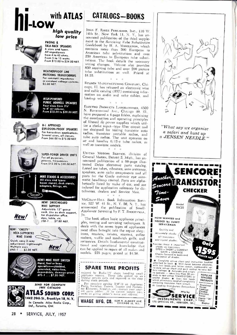
with ATLAS -LOW
high quality low price
PAGING 8 TALK -BACK SPEAKERS 6 sizes and types. All impedances from 4 to 45 ohms. From 5 to 15 watts. From 515.00 to $24.00 NET.
WEATHERPROOF LINE
MATCHING TRANSFORMERS For constant impedance or constant voltage systems. $5.00 NET.
HIGH-POWERED
PUBLIC ADDRESS SPEAKERS Four sizes from 21/4' to 6' air column. From $10.00 to, $39.00 NET.
U -L APPROVED
EXPLOSION -PROOF SPEAKERS For hazardous applications. Several sizes, all classes. From $66.00 to $75.00 NET,
7j SUPER -POWER DRIVER UNITS For all purposes, powers, frequencies.
1! From $ 15.00 to $30.00 NET,
_ " ti= S f
MIKE STANDS & ACCESSORIES All sizes and types: boom stands, desk stands, adapters, fittings, etc.
Mew!
rNEW! "CHESTY" NECK -SUPPORTED
' MIKE STAND
I Ouick, easy 3 -way adjustment. Lightweight. Multiple uses. ¡j6.15-1 ... $3.00 NET.
t1+ '
NEW! SWITCHBOARD MIKE SUPPORT Adjustable 12" goose neck. Use as desk support, for dispatcher office, dais, table, etc. 1158-1 ... $7.80 NET.
%
NEWT MIKE FOOT SWITCH Hand, foot or knee operation-shielded, grounded, noise -free, dependable, damage -proof.
`7 *FS -1 .. $7.20 NET.
SEND FOR COMPLETE ILIFREE CATALOG
ATLAS SOUND CORP. 1442 39th St., Brooklyn 18, N. Y.
In Canada: Atlas Radio Corp., Ltd., Toronto, Ont.
CATALOGS BOOKS
lollN F. RIDER PUBLISHER, INC., 116 \V. 14th St., New York 11, N. Y., has an- nounced publication of the third supple- ment to the Reecit'ing 7'ttbe Substitution Guidebook by II. A. \lII)l)LETON, which contains more than 200 European to American tube substitutions and over 230 American to European tube substi- tutions. The book details the necessary wiring changes. Volume also provides 830 receiving tube and over 200 picture tube substitutions as well. Priced at $1.35.
O o 0
BELDEN MANUFACTURING COMPANY, Chi- cago, Ill. has released an electronic wire and cable catalog (8.57) containing infor- mation on audio and mike cables, and hookup wire.
O 0 0
ELECTRO PRODUCT S LABORATORIES, 4500 N. li:lvenswoocl \ve., Chicago 40, III., have prepared a 4 -page folder, explaining the construction and operating principles of filtered tic power supplies which util- ize a choke input-type filter circuit and are designed for testing transistor auto radios, transistor portable radios, and tube auto radios. Ile unit operates on ac and handles 6/12-e tube radios, as well as transistor models.
a G C
UNITED MOTORS SERVICE, rliViSiOtl of General Nlotors, Detroit 2, Mich., has an- nounced publication of a 60 -page illus- trated Delco electronic parts catalog. Listed are tubes, vibrators, auto antennas, speakers, auto radio components and all parts for the Cuide autronic eye auto- matic headlamp control. Parts are alpha- betically listed by make of car, anc are indexed for application reference by dis- tributors, dealers and Service \len.
O 0 0
\IcGR\\v-IIILL Book Information Serv- ice, 327 \V. 41 St., N. Y. 36, N. Y., has announced the publication of Saud/ - Appliance Servicing by P. T. BROCkwaLL, IR.
The book oilers basic appliance princi- ples, testing and servicing techniques. It deals with the seven types of appliances most often brought into the repair shop: i ons, toasters, mixers, roasters, collee makers, waffle and sandwich grills, and rotisseries. Details fundamental construc- tional and operational kuowlt'dt e that can be applied to repair of all slakes .uld models. 2'S pages; priced at $4.50.
SPARE TIME PROFITS enjoyed by Radio -T\' shops handling small appliance repairs. These jobs picked up on -regular service calls and repaired at the shop during slack periods.
For complete catalog R\V-58 on Appliance Parts, Switches. testers, Toaster and Percola- tor Elements, Supplies, etc., contact your near- est parts jobber. If he cannot supply you, write us giving jobber's name and address.
WAAGE MFG. CO.
"What say we organize a safari and hunt up
a JENSEN NEEDLE."
r__ WI INN OE OM Mil MI
SENCORE¡ °'TRANSISTÓRI sc
CHECKER I
I I I I I I
I
63211 N. ALBANY AVE. I I 171 OFFICIAL RD., ADDISON, ILL. CHICAGO 12, ILL
Model TDC22
NOW WANTED and NEEDED by EVERY
SERVICEMAN
Ouiclly and accurately checks
all transistors and crystal diodes.
-
¿Daly$1s9.5 Provides these 4 important checks on transistors: I OPEN . SHORT . CURRENT
GAIN LEAKAGE Checks resistance ofrd
to diodeckw0rd
DEA(ERMir
* Complete setup chart and instruction booklet attached to bock * Will never become obsolete, Iwith test leads and inline socket, replaceable up- to-date setup chart and gain control to vary bat. tery voltage * Accurate and simple to operate - takes less than 30 sec - Iands to lest either TRANSISTORS or crystal diodes * Uses test leads Iwhich eliminates need of completely removing transistor from circuit. At Leading Distributors Everywhere
Isrñ Mfg by ISERVICE INSTRUMENTS CORP,
POPULAR SENCO5E
PRODUCTS
Transistor Tester Leakage Checker Filament Tester Handy "36" Vibre-
Dapter I pWI
1111111 MUM IZIMI MOW
I I
I I I I I I I
Ma\
28 SERVICE, JULY, 1957

ACCESSORIES VIBRATOR POWER SUPPLY
A VIHttATO1-po\\'el supply, Supreme 175, featuring a fan -cooled vibrator, is
now available from Terado Co., 1068
Raymond Ave., St. Paul 14, Minn. Unit rating of 175 to 200 u is said
to be ample for all requitem eats from a 12-v battery source. Supply can be
used for operation of portable TV sets,
power tools and tape recorders.
r
C O O
S Y
LINE VOLTAGE ADJUSTER
A LINE -VOLTAGE adjuster, LA 350, Or
boosting or reducing soilage to assure best operation at approximately 115 t;,
has been introduced by Anchor Products Co., 2712 \V. Montrose Ave., Chicago 18, Ill.
Unit, it is said, can increase or de- crease voltage approximately 10,. Four - position switch permits selection of off, normal, 10-v up and 10-v down. Input ranges from 1011 to 130 y; output from 110 to 120 v. Designed for 60 -cycle ac 3 -amp operation. For use with units rated up to 300 w.
O O O
COLOR -AUDIO -SCAN ADAPTERS Two \CCESSOItIES FOR .\DOING color and sound to the 13&K model 10110 Dyna- Scan video generator have been an- nounced by R&K \lanutactturing Co., 3731 N. Southport Ave., Chicago 13, III.
One item, the model C15 Color -Scan (shown below) adds crystal -controlled rainbow display (orange, red, magenta, blue, cyan, green). Permits testing of color sync circuits, checking hue -control range, alignment of color demodulators.
The second unit, model SI(1 Audio - Scan adds FM sound transmission 4.5 -me above video carrier, with modu- lation from any available audio source. Enables one to combine speech or music with video display. Can be modulated with built-in 400 -cycle tone generator for test signal or front external signal source.
UNI-DIRECTIONAL
MODEL 737A
You have your choice of three
SHURE moderately priced general-purpose microphones
SEMI -DIRECTIONAL
11
BI-DIRECTIONAL
MODEL 315
JN ,
MODEL 51
'NE" a
Where quality is essential, yet cost is a factor- you can rely on these SHURE Microphones FOR PUBLIC ADDRESS HOME RECORDING COMMUNICATIONS PAGING AND INTERCOM SYSTEMS
MODEL 737A "MONOPLEX": Uni-directional, moisture -proofed crystal microphone-reduces feedback by 67%! Can be used under adverse conditions of background noise where conventional microphones would be practically useless. "Humi-seal" Crystal for trouble -free operation even in humid climates. High impedance unit with excellent response to 10,000 cps. Output -54.0 db.
LIST PRICE $46.00 MODEL 51 "SONODYNE": Semi -directional, dynamic microphone. Switch for low, medium,
or high impedance makes it three microphones in one! Ideal for recording and "close -talking" applications. Frequency response is 60-10,000 cps, Output -52.5 db. Unusually rugged micro- phone; can be used in any climate, indoors or outdoors. LIST PRICE $49.50
MODEL 315 "GRADIENT": Bi-directional high fidelity microphone with multi -impedance switch. Picks up sound equally from front and rear; is "dead" at sides. Ideal for interview broadcasting or group recording. Frequency response 50-12,000 cps. Provides exceptional voice and music reproduction. Particularly useful in installations v. here feedback is a problem. Output -57 db.
LIST PRICE S85.00 All three units have rugged, die-cast metal cases and are finished in a rich Satin chrome.
SHURE BROTHERS, INC. Alicrophones -- Electronic Components
HARTREY AVENUE EVANSTON, ILLINOIS "In Electronics Since /925"

TEST INSTRUMENTS
.011P
.
i
- G I
I .
, :. _",_ : SZA..- a
CORWELLIDVE3tLIER
Auto Antenna Display
- I
i1.JN1Ft Ytitt
urt0/tiCE tttOvE ri
Indoor Antenna Soles Gilt
11At.t1 wtT /t. - i 1 ". « O ( 1 t / r I . 4 "
. __ '- 11446,....4,.
I
. ,-., w M
11111111.109'
-
r:OVw w TF! ;TO - . ~Ca r _4 , a./ A . arr
r u. V M s
3 SE ; C. .. .

BENCH -FIELD TOOLS SCREWDRIVER FOR TINY SCREWS
A VEDCE-\CTIOx screwdriver, Mini -hold,
designed to grip extremely tiny screws
(Nos. 1 to 4) has been announced by
\Valsco Electronics Alanufacturing Co.,
100 \V. Green St., Rockford, III. Screw-
driver measures 2J4" overall.
o o o
FURNITURE CLEAN -POLISH KIT
A MONTH -LONG TOOL SPECI AL, a TV and
Furniture Beauty Kit, has been an-
nounced by General Cement Manufac-
turing Co. ( Division of Textron, Inc.), 400 S. \Vvinan St.. Rockford, III.
Included in package is Creme-O-\Vax polish, skratch stiks in three different wood colors, and a squeeze bottle of
TV lens cleaner. o 0 0
MINIATURE SOLDERING IRON
A MINIATURE SOLDERING iron, for use
with miniaturized and printed circuitry, has been announced by the Industrial Heating Dept., General Electric Co.,
Schenectady 5, N. T.
\Veighing less than 1!_ ounces, the iron
features a tiny tubular heater, located in
the extreme tip, which develops a tem- perature of 750° to 850° F. Unit is rated
6 e, 12 w. Available with 6-v transformer integral with a 6' cordset.
o o o
ALLIGATOR CLIPS
A SERIES OF ALLIGATOR CLIPS Will"' cord
strain -relief ears and an extruded hinge, type 70, has been announced by \lueller Electric Co., 1573 E. 31 St., Cleveland 14, O.
Teeth have been designed to grip all shapes at different angles. Included in
the series are cadmium -plated steel units with or without screw (for soldering connection) and a solid copper clip with screw connection.
o o 0
FLEXIBLE GRIP PROBE
PLASTIC PROBE, Griprobe, to grip -hold terminals, tube sockets, lugs and wires, has been developed by Standard Electronics, Inc., 5523 Satsuma Ave., Burbank, Calif.
Features interior spring mechanism. Press of thumb releases a hook -shaped metal probe; removing thumb, closes self - lock grip.
MODEL 1000
3 SLIDE
TRANSPARENCIES
ARE SUPPLIED
1. Indian Head Pattern 2. White Dot Pattern 3. White Line Crosshatch Plus One Clear Acetate
These are broadcast quality and assure high -definition TV images. You can also transmit slides of any subject you wish.
C á
z ú Q
IS'#OWñ4'Y PICTURE or PATTERN at any time - ON ANY TV SET
For Servicing Black & White and Color TV
For Merchandising and Advertising Promotions
For Paging, Educational and Industrial Use
gi V
Js :1 O1'# -SCAN PICTURE AND PATTERN
VI DEO-GEN E RATOR Simplify and speed servicing with this unique, new, COMPLETE FLYING SPOT SCANNER. Produces com- posite video and sync signal that operates any standard VHF black and white or color TV receiver. Easily reproduces standard Indian Head test pat- tern or any other pattern-in home, shop or store- for proper TV set alignment; enables you to make all color TV static and dynamic convergence adjust- ments with stable White IDot and White Line pat- terns. Can be used with one or more standard TV receivers or fed into master antenna system. Repro- duces from any film transparency. Transmits mes- sages typed or written on clear acetate. Size: 161/2 in. long, 10% in. high, 91/2 $19995 in. wide. Net wt. 28 lbs. NET
EASILY ADD COLOR OR SOUND NEW MODEL CIS COLOR -SCAN Adds crystal -controlled full color rainbow display (orange, red, magenta, blue, cyan, green). In con- junction with the White Dot and White Line pat- terns, it makes the Model 1000 a complete color test instrument. Enables you to test color sync cir- cuits-check range of hue control-align color de- modulators, etc. Easy to install on chassis. lust 4 wires to connect Net, 51995
NEW MODEL 516 AUDIO -SCAN Adds FM sound transmission exactly like a TV station, 4.5 megacycles above video carrier, with modulation from any available audio source. En- o ables you to combine speech or music with the video display. Can be modulated with built-in 400 cycle tone generator for test signal or from external signal source such as microphone, tape recorder, FM -AM tuner, or audio oscillator. Can be used for aligning sound I.F. stages of intercarrier television set. Full 25 KC deviation similar to TV station. Has built-in audio amplifier and volume control. Input takes audio signals from .01 to 5 volts, low or high impedance. Simple to Install on chassis. Net, 52995
See your B8K distributor, or write for Bulletin 1000-S
B a K .MANUFACTURING; CO. 3726.N. Southport Ave. Chicago 13, Illinois Canada: Atlas Rodio Corp.t50 Win gold, Toronfó 10, Ont. Export: Empire Exporters, 439 Broadway, New York 13, N.Y.
z
v
\ W
SERVICE, JULY, 1957 31

UI Q Fn/
i1lDnuR I H u l
s`n 1 WE WI I
jPii'TPHEWTWIN
LEAD
More than 25% of all outdoor tv installa-
tions-more than 5,000,000 installations in
the United States alone-have been made
with AMPHENOL Twin Lead! These tremen-
dous sales figures reflect the popularity of
AMPHENOL Twin Lead with Dealers, popular-
ity founded on these important advantages:
PERFORMANCE: Good TV pictures depend upon the reliability of the entire set installation-AMPHENOL Irwin Lead is the strongest link in any system, a guarantee of better picture quality!
CUSTOMER SATISFACTION: Complete customer satisfaction is your key to repeat sales -AMPHENOL Twin Lead provides you with this key to better business, better profits!
GREATER PROFITS: As every Dealer and Serviceman knows, AMPHENOL Twin Lead provides plus profits on every sale-fair mark-ups to fair list prices!
EASY -TO -USE -HANKS: Complete customer satisfaction is your key to repeat sales- AMPHENOL Twin Lead Hanks make selling and installing easier. Popular lengths of 25, 50, 75 and 100 feet; also reels of 500 and 1000 feet.
Over 5.000.000 AMPHElto& outdoor Twin Lead Installations Have Shown The Way to Quality!
' ,a,>eurrty tl`PHEÑót:r
F;'f+:ir. .14,1r>
AMPHENOL ELECTRONICS CORPORATION chicapo 50, illinois
FM Mobile Receiver centinu..1 r... r t
1*ran t.t:e Of uateifereuce ill ieeluut .lecid atteeditu
\1 ¡tic the tcceiscr installed in the car and the antenna connected, the car motor should be started. ignition noise can lt distinguished In its
1 ty-
ping sound at idling speed. !'his se cuss be reduced b% installing a sup- pressor in the main high -%tillage lead, preterablh the type which is tvna- taimetl within the wiie itself. The spark plugs should lie replaced u ills resistor -types, or quality suppressut a
can be added at each sparl, plug. shielded h pe .5-tufd capacitor with a short lead should be connected to the armature terminal of the genera- tor to cot rect gruerator noise. A similar c,tp.tcitot can be used at tht s tillage regulator and other puiúts of interference.
Service Notes (Continual Irvin page 1,11
indication u ill In- materially ditleteut %% lieu the ohmmeter test prods ale res resell.
Not only will misleading indica- tions be obtained, hut the trans btu, s tlentse)s us can he permanently (laua- aged by resistance uteasurenuwmt.
11 resistance measurements are to be made iii a transistor radio, the transistors should be reutosed horn the circuit to be tested. If the trau- sistors are soldered in on a printed - circuit board, it ss ill be best to unsolder one terminal of the com- ponent to be tested.
Current measurements are seldom made in the seis icing of radios because of the difficult> in staking such measurements.
I loss ever, transistor circuit design is based primarily on current Hose and not upon soltage. Although current measurements are nut 'radii% Made, the to %tillage drop across circuit resistors can sometimes be used to pros ide a reasonably atvurate indica- tion of current.
In RCA tuodels 8-11T-9 and 9-I1T-43 tice no -signal emitter currents are as follow s.
(, l '_' \ 1401 .65 ma Q, (º \ 109) 1.2 ma (1. ( 2\ 139) .52 mica (1, (2\'1'141 1.8 alts Q, l 2 \ 139 I .95 mica (141 ( 2N:1091 1.8 mica
The collector currents in other models are of similar magnitude with the exception of models 8 -BT -7 and IS -11T-8. The audio amplifier of these two models is class A and the single output transistor has a rated no -signal emitter current of 10.7 ma; the cur- ret at has little variation with audio output variation.

110 TV Chassis
(Continued from page 12)
the ton and the bottom of the cabinet. In the console for this set, the chassis is mounted on a metal rail extending across the back of the receiver. The el. ,k is prevented from falling for -
h two small extensions, one ,t-,tth the tuner, and the other , ,,ding towards the right rear of
the cabinet. Screws ft'ont the back cost r go through these rails and through the metal extensions locking
' ,.sis ill place.
loriÑonta! Deflection Circuit
o,ss-st etional views of the new mid the old 70- yokes appear
2). It ll ted Hidings
p. llings of the tI to'
e ttstoke athat
I, the bell of the picture tube, core material of the yoke sd in a similar manner.
Ines added to the smaller toter add rip to .t y Ike nperior to that el the pre- ' deflection okes. 1 n ad -
the windings are fitted oke the center of de -
forward into the hull tube. This dcs:gu cit- ing to get .1 1 1(1
'íthout corner -cutting. with any deflection itself must be fully
the bell of the picture >peration. nultivibrator is used horizontal signal. It upled multi\ ibrator
popular 6(:C7. gn idea of the tg sy stmt was to can with approx- ir the picture tube rational and well
To do this, the vibrator was fed ,orizontal output its output tube ized, but very mer. Efficiency pendent upon 'ice Men are taterial used `ormer. But vare of, is
, whether 11 saturate
into the e core
(p. are gh
a
this
'
t : '
onth Only
worn' !¢¢
L _ ME SPEGIAV e ...Y. G -C SH..... ... ---` -- < < -'
1
TV AND
FURNITURE
BEAUTY
KIT
SPECIALLY PRICED FOR YOU
-AND YOUR CUSTOMERS! CONTAINS CREME -O -WAX POLISH
3 GENERAL SKRATCH STIKS FREE: G -C KLEER LENS
SELL A KIT ON EVERY SERVICE CALL! Here's a G -C "special" you can't afford to pass up ... the new TV & FURNITURE KIT. Contains every- thing you need to make TV and fine furniture finishes sparkle like new. Buy a kit for your shop ... sell one on every service call. Hurry . . . while this special offer lasts!
REGULAR LIST $380
THIS MONTH ONLY $Zss LIST
SEE YOUR G -C JOBBER NOW!
ttttl
GENERAL CEMENT MFG. CO.
9
Division of Textron Inc. 400 Stiuth.Wyman Street, Rockford, Illinois
creased magnetic flux will be de- veloped with an increase of applied electrical power. At this point the core of the transformer is considered to be saturated. In the lower section of the drawing, we see the same elec- tromagnet, except that an additional winding has been added. By follow- ing the current flowing through the winding, it can he observed that the current is flossing in apposite direc- tions through the two Windings; therefore, the magnetic field beino.
developed by the two windings Will
cancel. In conventional -scan transformers,
the core is partially saturated by the
(Ic flowing in the windings. This do is the B+ for the plate of the driver tube. This means that only a limited amount of rf power can be handled by the core material. To be conven- tional, simply enlarging the size of du core material would overcome this problem. Engineering did not want to do this as it would lead to other problems ín the transformer itself. Instead, it was felt that the portion of core material, that was being lost due to the do flowing in the horizontal scan transformer, should be elimin- ated. To do this, an additional wind- ing was placed on the horizontal scan
(Continued on page 34)
SERVICE, JULY, 1957 33

TEST INSTRUMENTS
1., Iways de eidáble... a
étter. qila/itfim'! design,..,
VIBRATOR, the complete line...
There is a CORRECT replacement C -D vibrator for every original installation... no guessing
...no problems! And every C -D vibrator delivers longer service that is dependable.., and quieter
in operation! AND.., the complete line of COMMUNICATION VIBRATORS answers every
replacement problem in this important field!
It's as basic as know-
ing your A B C D's... that C -D vibrators are
your best buys year 'round . .. day in and
day out! Look for the
famous CD seal ... it is your guarantee of quality combined with skilled engineering and
controlled manufacture!
CORNELL-DUBILIER Plants in South Plainfield, N. J.: New Bedford, Worcester and Cambridge, Mass.: Providence and Hope Valley, R. I.: IndIanapolls, Sanford, Varina and Fuquay Springs, N. C.: and Venice, California. Subsidiary: The Radlart Corporation, Cleveland. Ohio.
Auto Antenna Display
(Right) SALES KIT designed to hold three Snyder 10-D Imperial single -mast indoor TV an- tennas (blonde, mahogany and ebony) to permit showing of all three simulta- neously. Sales kit measures 18" by 28".
(Left) COUNTER STAND for Delco auto anten- nas, which features a mount to display the antenna and a pocket for carrying folders which describe the U -M -S line
of Delco auto antennas.
TRANSISTOR POWER SUPPLY
k TRANSISTORIZED REGULATED POWER supply, Transiply, has been introduced by Kay Electric Company, 14 Maple Ave., Pine Brook, N. J.
Unit is said to provide characteristics of an infinite life battery, and incorpo- rates flexibility of a continuously vari- able output voltage.
\lay be used as power supply for transistor circuitry, and to regulate fila- ment and bias currents.
ttQ/1S1ply Mr KM:
3 DC
5
VOL TS ELECTRIC CO.
13 MIA OM. INCREASE o "."'--A"."'--Ar,.`
KAY ELCi.sRICCO. oL I mn. :TT.r :f N a
O o 0
FLUTTER METER A FLUTTER AND \VO\V METER, FL -3D, to measure flutter content in recording and reproducing systems as established by the IRE, AS and SM PTE, has been de- veloped by D & 11, Ltd., 402 E. Gutierrez St., Santa Barbara, Calif. Device offers selectable wow and flutter filters, and rms calibration.
o o o
IMPEDANCE BRIDGE KIT
AN IMPED\NCE BRIDGE 1B -2A (kit), has been announced by Ileath Co., Benton Ilarbor 11, Nlich. Features constant fila- ment voltage, built in power supply, a 1000 -cycle generator, and vacuum -tube detector. A 100-0-100 µa méter provides for null indications. Measures resistance from 0-1 ohm to 10 megohms; capaci- tance from 10 mmfd to 100 infd; in- ductance from 10 mli to 100 h; and storage factor (Q) from 0.1 to 1,000.
Employs Wheatstone, capacity com- parison, Maxwell and Hay bridges.
Indoor Antenna Sales Kit
~
30 SERVICE, JULY, 1957

BENCH -FIELD TOOLS SCREWDRIVER FOR TINY SCREWS
A WEDGE- ACTION screwdriver, Mini -hold,
designee) to grip extremely tiny screws
(\os. I to 4) has been announced by
\Valsco Electronics Dlanufacturing Co.,
100 \V. Green St., Rockford, Ill. Screw-
driver measures 2J1" overall.
O o 0
FURNITURE CLEAN -POLISH KIT
A MONTH -LONG TOOL SPECIAL, a TV and
Furniture Beauty Kit, has been an-
nounced by General Cement Manufac-
turing Co. (Division of Textron, Inc.), 100 S. \Vvman St., Rockford, Ill.
Included in package is Creme-O-\Vax polish, skratch stiks in three diflerent wood colors, and a squeeze bottle of
T\/ lens cleaner. O 0 0
MINIATURE SOLDERING IRON
\ NIINI\TURF, SOLDERING iron, for use
with miniaturized and printed circuitry, has been announced by the Industrial Heating Dept., General Electric Co.,
Schenectady 5, 1\. Y.
Weighing less than PA ounces, the iron
features a tin; tubular heater, located in
the extreme tip, which develops a tem-
perature of 750° to 850° F. Unit is rated 6 u, 12 w. Available with 6-v transformer integral with a 6' cordset.
O 0 0
ALLIGATOR CLIPS
\ SERIES OF ALLIGA1O1t CLIPS with cord strain -relief ears and an extruded hinge, type 70, has been announced by Mueller Electric Co., 1573 E. 31 St., Cleveland 14, O.
Teeth have been Ilesigned to grip all shapes at different angles. Included in
the series are cadmium -plated steel units with or without screw (for soldering connection) and a solid copper clip with screw connection.
O o o
FLEXIBLE GRIP PROBE
\ PLASTIC PROBE, Griprobe, to grip -hold terminals, tube sockets, lugs and wires, has been developed by St an d a r d Electronics, Inc., 5523 Satsuma Ave., 3urbank, Calif.
Features interior spring mechanism. Press of thumb releases a hook -shaped metal probe; removing thumb, closes self - lock grip.
CLOSED
$$$.M T PICTURE or PATTERN
V ,
Fs -
MODEL 1000
3 SLIDE
TRANSPARENCIES
ARE SUPPLIED
1. Indian Head Pattern 2. White Dot Pattern 3. White Line Crosshatch Plus One Clear Acetate
These are broadcast quality and assure high definition TV images. You can also transmit slides of any subject you wish.
W - z
u
at any time - ON ANY .T V SET
For Serviring Black & White and Color TV
For Merchandising and Advertising Promotions
For Paging, Educational and Industrial Use
ONl1A-SCAN PICTURE AND PATTERN
VIDEO -GENERATOR Simplify and speed servicing with this unique, new, COMPLETE FLYING SPOT SCANNER. Produces com- posite video and sync signal that operates any standard VHF black and white or color TV receiver. Easily reproduces standard Indian Head test pat- tern or any other pattern-in home, shop or store- for proper TV set alignment; enables you to make all color TV static and dynamic convergence adjust- ments with stable White Dot and White Line pat- terns. Can be used with one or more standard TV receivers or fed into master antenna system. Repro- duces from any film transparency. Transmits mes- sages typed or written on clear acetate. Size: 161/2 in. long, 10% in. high, 91/2 519995 in. wide. Net wt. 28 lbs. NET
EASILY ADD COLOR OR SOUND NEW MODEL C15 COLOR -SCAN Adds crystal -controlled full color rainbow display (orange, red, magenta, blue, cyan, green). In con- junction with the \\'hite Dot and White Line pat- terns, it makes the Model 1000 a complete color test instrument. Enables you to test color sync cir- cuits-check range of hue control-align color de- modulators, etc. Easy to install on chassis. Just 4 wires to connect Net, $1995
NEW MODEL 516 AUDIO -SCAN Adds FN sound transmission exactly like a TV station, 4.5 megacycles above video carrier, with modulation from any available audio source. En- ables you to combine speech or music kl ith the video display. Can be modulated with built-in 400 cycle tone generator for test signal or from external signal source such as microphone, tape recorder, FM -AM tuner, or audio oscillator. Can be used for aligning sound I.F. stages of intercarrier television set. Full 25 KC deviation similar to TV station. Has built-in audio amplifier and volume control. Input takes audio signals from .01 to 5 volts, low or high impedance. Simple to install on chassis. Net, $2995
See your 88K distributor, or write for Bulletin 1000.5
Bat k MANUFACTURING.. C.O. 3726 N. Southport Ave. Chicago 13; Illinois Canada: Atlas Rodio Corp.40 Wingold, Toronto 10, Ont. Export: Empire Exporters, 439 Broadway, New York 13, N.Y.
SERVICE, JULY, 1957 31

TEST INSTRUMENTS
/ways dependable...
; otter quaity 9áfid 9' r
{
VIBRA TOR the complete line...
There is a CORRECT replacement C -D vibrator for every original installation... no guessing
...no problems! And every C -D vibrator delivers longer service that is dependable... and quieter
in operation! AND... the complete line of COMMUNICATION VIBRATORS answers every replacement problem in this important field!
It's as basic as know-
ing your A B C D's... that C -D vibrators are
your best buys year 'round ... day in and
dpy out! Look for the
famous CD seal ... it is your guarantee of quality combined with skilled engineering and
controlled manufacture!
CORNELL- DUBILIER Plants in South Plainfield, N. J.: New Bedford, Worcester and Cambridge, Mass.: Providence and Hope Valley, R. I.: Indianapolis, Ind,: Sanford, Varina and Fuquay Springs, N. C.: and Venice, California. Subsidiary: The Radiart Corporation, Cleveland, Ohio.
Auto Antenna Display
(Right) SALES KIT designed to hold three Snyder 10-D Imperial single -mast indoor TV an- tennas (blonde, mahogany and ebony) to permit showing of all three simulta- neously. Sales kit measures 18" by 28".
(Left) COUNTER STAND for Delco auto anten- nas, which features a mount to display the antenna and a pocket for carrying folders which describe the U -M -S line
of Delco auto antennas.
TRANSISTOR POWER SUPPLY
A TRANSISTORIZED REGULATED POWER supply, Transiply, has been introduced by Kay Electric Company, 14 Maple Ave., Pine Brook, N. J.
Unit is said to provide characteristics of an infinite life battery, and incorpo- rates flexibility of a continuously vari- able output voltage.
May be used as power supply for transistor circuitry, and to regulate fila- ment and bias currents.
VO114'.LTS
I' ELECTRIC co.
e ON INCREASE .,"
V !,.
Q.) KAY ELL.i.I RIC CO. . _ o,u, NRA7K N 1 _
o o 0
FLUTTER METER A FLUTTER AND wOw METER, FL -3D, to measure flutter content in recording and reproducing systems as established by the IRE, kS \ and S\IPTE, has been de- veloped by D & It, Ltd., 402 E. Gutierrez St., Santa Barbara, Calif. Device offers selectable wow and flutter filters, and rills calibration.
o o 0
IMPEDANCE BRIDGE KIT
AN IMPEDANCE BRIDGE 1B -2k (kit ), has been announced by Heath Co., Benton Harbor 11, Mich. Features constant fila- ment voltage, built in power supply, a
1000 -cycle generator, and vacuum -tube detector. A 100-0-100 µa méter provides for null indications. Measures resistance from 0-1 ohm to 10 megohms; capaci- tance from 10 mmfd to 100 mfd; in- ductance from 10 mh to 100 h; and storage factor (Q) from 0.1 to 1,000.
Employs Wheatstone, capacity com- parison, Maxwell and Hay bridges.
Indoor Antenna Sales Kit
"`
30 SERVICE, JULY, 1957

ti
BENCH -FIELD TOOLS SCREWDRIVER FOR TINY SCREWS
A v) i)CE-ACTION screwdriver, Mini -hold,
designed to grip extremely tiny screws
( \os. 1 to 4) has been announced by
\Valsco Electronics Manufacturing Co.,
100 W. Green St., Rockford, Ill. Screw-
driver measures 21e" overall.
-:-J 1
o o o
FURNITURE CLEAN -POLISH KIT
A MONTH -LONG TOOL SPECIAL, a TV and
Furniture Beauty Kit, has been an-
nounced by General Cement Manufac-
turing Co. (Division of Textron, Inc.), 400 S. \Vyman St., Rockford, Ill.
Included in package is Creme-O-\Vax
polish, skratch stiks in three different
wood colors, and a squeeze bottle of
TV lens cleaner. o o o
MINIATURE SOLDERING IRON
A MINIATURE SOLDERING iron, for use
with miniaturized and printed circuitry, has been announced by the Industrial Heating Dept., General Electric Co.,
Schenectady 5, N. Y.
Weighing less than I;z ounces, the iron
features a tiny tubular heater, located in
the extreme tip, which develops a tem-
perature of 750° to 850° F. Unit is rated 6 v, 12 w. \vailable with 6-v transformer integral with a 6' cordset.
o o O
ALLIGATOR CLIPS
A SERIES OF ALLIGATOR CLIPS \VÍth cord
strain -relief ears and an extruded hinge, type 70, has been announced by Mueller Electric Co., 1573 E. 31 St., Cleveland 14, O.
Teeth have been designed to grip all shapes at different angles. Included in
the series are cadmium -plated steel units with or without screw (for soldering connection) anll a solid copper clip with screw connection.
O 0 0
FLEXIBLE GRIP PROBE
A PL 1S I1C PROBE, Griprobe, to grip -hold terminals, tube sockets, lugs and wires, has been developed by Standard Electronics, Inc., 5523 Satsuma Ave., Burbank, Calif.
features interior spring mechanism. Press of thumb releases a hook -shaped metal probe; removing thumb, closes self - lock grip.
,# "
-70.40.00
CLOSED I
4SWGV441w pIçTUREipATTERN at any time -CON 'ANY .TV SET
0N,--9C1N pp7,
/ 1 J ...
. , .- 111
dB
rtitil , ,l1
a:J
MODEL 1000
3 SLIDE
TRANSPARENCIES
ARE SUPPLIED
1. Indian Head Pattern 2. White Dot Pattern 3. White Line Crosshatch Plus One Clear Acetate
These are broadcast quality and assure high -definition TV images. You can also transmit slides of any subject you wish.
For Servicing Black & White and Color TV
For Merchandising and Advertising Promotions
For Paging, Educational and Industrial Use
MINl1A-SCAN PICTURE AND PATTERN
VIDEO -GENERATOR Simplify and speed servicing with this unique, new, COMPLETE FLYING SPOT SCANNER. Produces com- posite video and sync signal that operates any standard VHF black and white or color TV receiver. Easily reproduces standard Indian Head test pat- tern or any other pattern-in home, shop or store- for proper TV set alignment; enables you to make all color TV static and dynamic convergence adjust- ments with stable White Dot and White Line pat- terns. Can be used with one or more standard TV receivers or fed into master antenna system. Repro- duces from any film transparency. Transmits mes- sages typed or written on clear acetate. Size: 161/2 in. long, 10% in. high, 91/2 519995 in. wide. Net wt. 28 lbs. NET
EASILY ADD COLOR OR SOUND NEW MODEL C15 COLOR -SCAN Adds crystal -controlled full color rainbow display (orange, red, magenta, blue, cyan, green). In con- junction with the White Dot and White Line pat- terns, it makes the Model 1000 a complete color test instrument. Enables you to test color sync cir- cuits-check range of hue control-align color de- modulators, etc. Easy to install on chassis. Just 4 wires to connect Net, $1995
NEW MODEL 516 AUDIO -SCAN Adds FM sound transmission exactly like a TV station. 4.5 megacycles above video carrier, with modulation from any available audio source. En- ables you to combine speech or music with the video display. Can be modulated with built-in 400 cycle tone generator for test signal or from external signal source such as microphone, tape recorder, FM -AM tune!, or audio oscillator. Can be used for aligning sound I.F. stages of intercarrier television set. Full 25 KC deviation similar to TV station. Has built-in audio amplifier and volume control. Input takes audio signals from .01 to 5 volts, low or high impedance. Simple to install on chassis. Net, $2995
See your B&K distributor, or write for Bulletin 1000-S
B.a K ..MANUFACTURING . CO. 3721N. Southport Ave. Chicago 13, Illinois Canada: Atlót Radio Corp.t50 Wingold, Torontó 10, Ont. .Export: Empire Exporters, 439 Broadway, New York 13, N. Y.
SERVICE, JULY, 1957 31

ONE"OUT OF fOUR
OUTDOOR
INSTALLATIONS
ARE MADE WITH
TWIN LEAD
.,. oM4:`'`
4)
More than 25% of all outdoor tv installa-
tions-more than 5,000,000 installations in
the United States alone-have been made
with AMPHENOL Twin Lead! These tremen-
dous sales figures reflect the popularity of
AMPHENOL Twin Lead with Dealers, popular-
ity founded on these important advantages:
PERFORMANCE: Good TV pictures depend upon the reliability of the entire set installation-AMPHENOL Twin Lead is the strongest link in any system, a guarantee of better picture quality!
CUSTOMER SATISFACTION: Complete customer satisfaction is your key to repeat sales -AMPHENOL Twin Lead provides you with this key to better business, better profits!
GREATER PROFITS: As every Dealer and Serviceman knows, AMPHENOL Twin Lead provides plus profits on every sale-fair mark-ups to fair list prices!
EASY -TO -USE -HANKS: Complete customer satisfaction is your key to repeat sales- AMPHENOL Twin Lead Hanks make selling and installing easier. Popular lengths of 25, 50, 75 and 100 feet; also reels of 500 and 1000 feet.
Over 5.000,000 AMPHENOL outdoor Twin Lead Installations Have Shown The Way to Quality!
AMPHENOL ELECTRONICS CORPORATION chicago 50, illinois
FM Mobile Receiver (Continued from page 9)
horn case of interference will require special attention.
\Vith the receiver installed in the car and the antenna connected, the car motor should be started. Ignition noise can be distinguished by its pop- ping sound at idling speed. This noise may be reduced by installing a sup- pressor in the main high -voltage lead; preferably the type which is con- tained within the wire itself. The spark plugs should he replaced with resistor -types, or quality suppressors can he added at each spark plug. A shielded type .5-mfd capacitor with a short lead should be connected to the armature terminal of the genera- tor to correct generator noise. A similar capacitor can he used at the voltage regulator and other poiñts of interference.
Service Notes (Continued from page 14)
indication will be materially different when the ohnnneter test prods are reversed.
Not only will misleading indica- tions be obtained, but the transistors themselves can be permanently dam- aged by resistance measurement.
If resistance measurements are to be made in a transistor radio, the transistors should be removed from the circuit to be tested. If the tran- sistors are soldered in on a printed - circuit board, it will be best to unsolder one terminal of the com- ponent to be tested.
Current measurements are seldom made in the servicing of radios because of the difficulty in making such measurements.
However, transistor circuit design is based primarily on current flow and not upon voltage. Although current measurements are not readily made, the do voltage drop across circuit resistors can sometimes be used to provide a reasonably accurate indica- tion of current.
In RCA models 8 -BT -9 and 9-13T-9 the no -signal emitter currents are as follows:
Q, (2N140) .65 ma O. (2N139) .52 ma Q, (2N139) .95 ma
Q, (2N109) 1.2 ma Q, ( 2N 109 ) 1.8 ma Qu(2N109) 1.8 ma
The collector currents in other models are of similar magnitude with the exception of models 8 -BT -7 and 8 -BT -8. The audio amplifier of these two models is class A and the single output transistor has a rated no -signal emitter cun-ent of 10.7 ma; the cur- rent has little aria tion with audio output variation.

110° TV Chassis (Continued from page 12)
the too and the bottom of the cabinet. in the console for this set, the chassis
is mounted on a metal rail extending across the hack of the receiver. Ile chassis is prevented from falling for- ward by two small extensions, one
underneath the tuner, and the other extending towards the right rear of the cabinet. Screws from the back
cover go through these rails and
through the metal extensions locking the chassis in place.
The Horizontal Deflection Circuit
Cross-sectional views of the new 110° and the old 70° yokes appear in Fig. 3 (p. 12). it will be noted that the windings of the 110° yoke are
flared onto the bell of the picture tube, and that the core material of the yoke
itself is flared in a similar manner. These features added to the smaller neck diameter add up to a yoke efficiency superior to that of the pre- viously -used deflection yokes. In ad-
dition, since the windings are flared on the 110° yoke, the center of de-
flection is now forward into the bell of the picture tube. This desfgn en-
abled engineering to g;et a 110°
diagonal scan without corner -cutting. Of course, as with any deflection yoke, the yoke itself must be fully forward against the bell of the picture tube for proper operation.
A horizontal multivibrator is used
to develop the horizontal signal. It
is a cathode -coupled multivibrator using the new popular 6CC7. The basic design idea of the horizontal scanning system was to develop a 110- scan with approx- imately 17,000 v for the picture tube by utilizing conventional and well known driver tubes. To do this, the output of the multivibrator was fed to the grid of the horizontal output tube, a 121)96. This output tube drives a new small -sized, but very efficient output transformer. Efficiency of this transformer is dependent upon cancellation of flux. Service Men are familiar with the core material used in a horizontal scan transformer. But what they may not be aware of, is
that with all electromagnets, whether they be do or «c, the core will saturate if the amount of power put into the windings is greater than the core material can handle.
This point is illustrated in Fig. 4 (p. 12), where two electromagnets are shown. If de is caused to flow through the windings on the upper magnet, a
point will be reached where no in-
V ana
¡¡.rs--1 yt° " .
Fk«.`,
i 11
: .
7151t .1\10/1 í 11
TV AND
.FURNITURE
BEÁUTY
KIT
SPECIALLY PRICED FOR YOU
-AND YOUR CUSTOMERS! á.
.5I111411. ,\1 .-ti ,.wc
Sv?,
,,n ra t - ¡ r
C swop ,d HOME SPECIAL
..........`_ `r
.w r
CONTAINS CREME -O -WAX POLISH
3 GENERAL SKRATCH STIKS FREE: G -C KLEER
SELL A KIT ON EVERY SERVICE CALL! Here's a G -C "special" you can't afford to pass up ... > t the new TV & FURNITURE KIT. Contains every- thing you need to make TV and fine furniture finishes sparkle like new. Buy a kit for your shop ... sell one on every service call. Hurry . . . while this special offer lasts!
REGULAR LIST $380
THIS MONTH ONLY $255 LIST
SEE YOUR G -C JOBBER NOW!
GENERAL CEMENT MFG. CO. Division of Textron Inc. 400 South Wyman Street, Rockford, Illinois
creased magnetic flux will be de- veloped with an increase of applied electrical power. At this point the core of the transformer is considered to be saturated. In the lower section of the drawing, we see the same elec- tromagnet, except that an additional winding has been added. By follow- ing the current flowing through the winding, it can be observed that the current is flowing in opposite direc- tions through the two windings; therel ore, the magnetic field being developed by the two windings \vill car rcel.
In conventional -scan transformers, the core is partially saturated by the
dc flowing in the windings. I his dc is the B+ for the plate of the driver tube. This means that only a limited amount Of rf power can be handled by the core material. lo be conven- tional, simply enlarging the size of the core material would overcome this problem. Engineering did not want to do this .as it would lead to other problems in the transformer itself. Instead, it was felt that the portion of core material, that was being Iost due to the do flowing in the horizontal scan transformer, should be elimin- ated. To do this, an additional wind- ing was placed on the horizontal scan
(Continued on page 34 )
SERVICE, JULY, 1957 33

FM Mobile Rec&i . eq
TWIN LEAD
(
® i
S4>rvic Notes

110` TV Chassis
(Continued from page 12)
the too and the bottom of the cabinet. In the console for this set, the chassis
is mounted on a metal rail extending across the back of the receiver. The
chassis is prevented front falling for-
ward by two small extensions, one
underneath the tuner, and the other extending towards the right rear of
the cabinet. Screws from the back
cover go through these rails and
through the metal extensions locking the chassis in place.
The Horizontal Deflection Circuit
Cross-sectional views of the new 110° and the old 70° yokes appear
in Fig. 3 (p. 12). It will be noted that
the \vindings of the 110° yoke are
flared onto the bell of the picture tube, and that the core material of the yoke
itself is flared in a similar manner. These features added to the smaller neck diameter add up to a yoke
efficiency superior to that of the pre- viously -used deflection yokes. In ad-
dition, since the \yindings are flared on the 110° yoke, the center of de- flection is now forward into the bell of the picture tube. This design en-
abled engineering to get a 110°
diagonal scan without corner -cutting. Of course, as with any deflection yoke, the yoke itself must be fully forward against the bell of the picture tube for proper operation.
A horizontal multivibrator is used
to develop the horizontal signal. It is a cathode -coupled multivibrator using the new popular 6CC7. The basic design idea of the horizontal scanning system was to develop a 110' scan with approx- imately 17,000 y for the picture tube by utilizing conventional and well known driver tubes. To do this, the output of the multivibrator was fed to the grid of the horizontal output tube, a 19-1)Q6. This output tube drives a new small -sized, but very efficient output transformer. Efficiency of this transformer is dependent upon cancellation of flux. Service \len are familiar with the core material used in a horizontal scan transformer. But what they may not be aware of, is that with all electromagnets, whether they be do or ac, the core will saturate if the amount of power put into the windings is greater than the core material can handle.
This point is illustrated in Fig. 4 (p. 12), where two electromagnets are shown. If do is caused to flow through the windings on the upper magnet, a
point will be reached where no in-
,t
This onth Only °ty,, 1.+
V ,K1't irj_ Tj
vanélÑ'alI1I11 t --
G -C SN
-í +-+.1 II CST/
TV AND
FURNITURE
BEÁUTY
KIT ff,;--
SPECIALLY PRICED FOR YOU
-AND YOUR CUSTOMERS! CONTAINS CREME -O -WAX POLISH
3 GENERAL SKRATCH STIKS FREE: G -C KLEER LENS
SELL A KIT ON EVERY SERVICE CALL! Here's a G -C "special" you can't afford to pass up .. .
the new TV & FURNITURE KIT. Contains every- thing you need to make TV and fine furniture finishes sparkle like new. Buy a kit for your shop ... sell one on every service call. Hurry . . . while this special offer lasts!
REGULAR LIST
THIS MONTH ONLY
$3ao
$255 LIST
SEE YOUR G -C JOBBER NOW!
el° ,
GENERAL CEMENT MFG. CO... Division of Textron Inc. 400 South Wyman Street, Rockford, Illinois
/ t
creased magnetic flux will be de- veloped with an increase of applied electrical power. At this point the core of the transformer is considered to be saturated. In the lower section of the drawing, we see the same elec- tromagnet, except that an additional winding has been added. By follow- ing the current flowing through the winding, it can be observed that the current is flowing in opposite direc- tions through the two windings; therefore, the magnetic field being developed by the two windings will cancel.
In conventional -scan transformers, the core is partially saturated by the
do flowing in the windings. This dc is the B+ for the plate of the driver tube. This 'mans that only a limited amount of t f power can be handled by the core material. To be conven- tion'.tl, simply enlarging the size of the core material would overcome this problem. Engineering did not want to do this as it would lead to other problems in the transformer itself. Instead, it was felt that the portion of core material, that was being lost due to the dc flowing in the horizontal scan transformer, should be elimin- ated. To do this, an additional wind- ing was placed on the horizontal scan
(Continued on page 31)
SERVICE, JULY, 1957 33

P q MALLOAY CO-Anco
ALLORY
CIippings. .
(A series of service hints gleaned from the notebooks of Mallory design and application engineers)
Once in a while, on some special service job, you're apt to need a non -polarized capacitor. Here's a way to make temporary repairs until you can get down to your distributor's for a Mallory replacement. Use a common negative dual capacitor, each section having the same voltage rating and twice the capacity rating as the unit being replaced. Use the two positive leads only- don't connect the negative lead (or the can) to anything, just insulate them well! Assuming sufficient physical space, the same thing can be done with two single capacitors- by connecting the negative leads together and insulating them, and the cans, carefully. Use the two positive leads. Of course, for an exact replacement or temporary repairs such as above, you ought to use Mallory FP Capacitors. They're tougher, longer lived, and plenty dependable-but, you probably know that from experience. See your Mallory Distrib- utor today-lay in a working replacement stock.
ALLORV 8 CO. inc. f,
P. R. MALLORY & CO. Inc., INDIANAPOLIS 6, INDIANA
Capacitors Controls Vibrators Resistors Switches Rectifie,s Power Supplies Filters Mercury and Zinc -Carbon Batteries
110° TV Chassis
(Continued front page 33)
transformer in the same direction as the main auto -winding. By proper circuit connections, the B+ current for the horizontal output tube is made to flow in one direction through the additional winding, and in the other direction through the main auto - winding. In other words, the B+ is flowing in one direction for one wind- ing, and in the opposite direction for the other winding. This opposite do flow vill cause field cancellation of the dc component. Therefore, all the core material can be used to handle the rf energy; this is shown in Fig.5 (p. 12). This means that a much smaller core material can be used over con- ventional transformers. This increased efficiency, in conjunction with the new high sensitivity yoke, eliminated the scan problem that vas antici- pated.
The Vertical Deflection Circuit
The vertical deflection circuit (Fig. 6; p. 12) incorporates a dual -triode tube. This is a new type tube, the 10ÚE7, specifically designed for this application. It is a dissimilar triode; that is, one of the triode sections has a lower plate dissipation than the other.
Although we have a plate -coupled multi\ ibrator circuit, one triode is de- veloping considerable power to drive the yoke. The feedback circuits to maintain this oscillator are from plate pin 1 back through Ca,, R314, and C,,,_ to grid pin 7. The other feedback circuit is front plate pin 6 through C313 to grid pin 2. The free running frequency of this oscillator is
controlled by adjusting 8317 which changes the rate of discharge of C3,á and Ca,... These capacitors are charged each time VOA draws grid current. By de- creasing the resistance of 113,7, the dis- charge time is shortened and the oscillator speeds up.
Some of the B+ voltage for VOA is
drawn front boost through the height control in series with thermistor This thermistor is in the circuit to con- trol picture size change during warmup time. This is necessary as the dc resis- tance of the yoke changes as it warms up. This upsets the circuit in such a
manner that the picture would change height if this thermistor were not in the circuit. At the same time, this change in resistance of the yoke could cause the vertical speed of the circuit to change. In order to prevent this, thermistor Rsn is located in the feedback circuit front plate pin 1 to grid pin 7. These thermis- tors will prevent any change in picture size or hold during warmup.
The left triode section of the 10DE7 (V5.á) receives its plate supply voltage front two different sources, both of which
34 SERVICE, JULY, 1957

go through the height control R. The primary source is through Raet to the 250-v 3+ source. The other source is
through the therrnistor Ra= to B boost.
If V., were not returned to B-{-, the oscillator would be slow ín starting as B
boost is the last voltage to he developed after the receiver is turned on. There- fore, no protective grid bias would be
available for Von. This bias voltage is
developed across the RC network in the grid of V,,,. \Vith 13+ available immedi- ately to both sections, the oscillator will start, developing its protective bias, even though it may be running at reduced amplitude. \Vhen boost voltage is avail- able from the 1(o supply, the oscillator will lock in at the proper amplitude and linearity. In addition a small amount of protective bias is incorporated in the tri- ode output section by R. which is by- passed by
Cs., a .47-nifd capacitor, is located across the deflection coil. This prevents pulses from the horizontal winding being coupled hack into the vertical output tube. This large capacitor has a very
low reactance at 15,50 cps, and acts as
a short circuit to pulses of this fre-
quency. however, the reactance is high enough at 60 cps to prevent severe load-
ing. It horizontal pulses were allowed to
leed back into the vertical oscillator cir- cuit, it would disrupt interlace.
lictrace blanking is accomplished by developing a pulse in the vertical retrace plate PI',IIII. This pulse is developed by the discharge of Can through R__, and
C_.,. This negative -going pulse is coupled to grid pin 5 of the 210 )1'4 picture tube and is used to drive the picture tube into cutoff during vertical retrace time.
0 0 0
PLASTIC FUSE CADDY
A PLASTIC caddy, designed to fit into a
compartment in a tube caddy, has been announced by Littelfuse, Inc., Des Plaines, Ill. Contains an assortment of 15 LC (limited current) fuse types said to cover 94% of service requirements for this new type of fuse. Caddy has 3
spare compartments for carrying of addi- tional lases.
LC fuses have been developed to make it physically impossible to fuse equipment at a higher rating than the manufacturers originally intended.
a $10.00 investment that could easily be the most important
in your entire technical career
-RIDER'S NEbyWDr. Al BASIexanderchureC
TELEVISION - S
This new 5 volume addition to the famous "picture book" courses is the most understand- able presentation of black and white television receiver theory at the basic level ever pub- lished. Complete 5 -volume course employs the famous Rider "picture book" method to explain basic theory of black and white television. Text is
supported by more than 450 large carefully prepared interesting and informative draw- ings that make the explanation of each im- portant idea crystal-clear. There is one idea. one thought in both text and picture on each page. This 6 -volume course is basic-yet covers every Precept of black and white television. It is
perfect for home study or classroom. It is
easy to read --you get right to the heart of the subject-maximum fact, minimum wordage. It starts with the transmitter and discusses in detail the following subjects: Volume 1,
the transmitter: the handling and the opera- tion of the camera: formation of the picture signal and the general content of the trans- mitter. Volume 2 covers the organization of the entire TV receiver treating each section individually from antenna to picture tube. Volumes 3, 4 and 5 treat with TV receiver circuit explanations. Each volume covers a
specific number of sections in the receiver. In
effect, the presentation is like a spiral-first an overall view of the whole, and then the
detailed explanation of each part. The most
perfect modern teaching technique. The result -maximum understanding.
Valuable to both the professional technician and the beginner because it is so comprehen- sive. so accurate and so easy to read and understand. However, it is specifically directed towards those technicians who are in the early stages of their career-and to beginners. Ideal for apprentice training in every service or- ganization which is conducting an on-the-job training program. Perfect to keep handy in the shop for reference. The entire story of black and white television receiver theory will be at your fingertips with this new Rider S -volume course. 'There is no similar television course like it anywhere in the free world. Reserve your copies today at your local jobber or bookstore or by ordering direct. Your 510
investment can easily be the most important you ever made in your entire technical career. X198-soft cover, 5 vols. 590 pages (approx.) S10.00 per set. 198-H all 5 volumes in a single cloth covered binding, 511.50.
A MUST FOR
EVERY ,TECHNICIAN 3rd SUPPLEMENT to
RECEIVING TUBE
SUBSTITUTION GUIDEBOOK
by H.- A: Middleton more than 330 latest receiving tube Sub- .
stifutloni , more thán .200 picture tube substitutions
more 'than 230 American to. European tube substitutions mole than 200 European to American tube substitutions an accumulative Index listing of the tube types treated' In the basil botik "and the
- :3 supplements, .
It pays for itself almost imme- diately. Reserve your copy at .your jobber 'today:
139-3, 8 #1/2 x 11!', 11.35 O REPAIRING TELEVISION RECEIVERS by Cyrus Glickstein The most modern completely practical book, written by an expert with long experience in television receiver repair. Devoted to troubleshooting and repair techniques which are modern, yet down- to-earth. Covers the use of simple as well as elaborate test equipment of all kinds. Profusely illustrated. This is not a theory book. It is a guide which every practicing TV technician, every student of TV repair and every newcomer to the TV. repair business can use to exceptionally good advantage, because it explains step-by-step pro- cedures. Soft Cover, 212 pp., 51,2 x 8'/2", illus. #191 Only S4.40
If 10U VAST THE BEST IN TV SERVICE INFORMATION
rNItCO 61 (MIRtON SrIY.NI. t(NItN W1S(INGNOYSI
.OMI(( 1C A MOtOfO( NOM.N (ROtltr CRAfCAl((
C..." nd.u,, t50u>.
RIDER'S NEW S D O SERVICE (",.-,t ..,._ .-t, -I
ONLY 30, rU CHASSIS At roue lOCat )ODU
TV PICTURE TUBE -CHASSIS GUIDE by Rider Lab Staff No busy service technician can afford to be without this easy -to -use TV tube location guide. It covers all picture tube types used in TV re- ceiver production from 1946 to February 1957-over 7.000 listings, This reference guide is organized by chassis number, and in some cases, by models so that the technician can immediately locate the correct pic- ture tube type simply by knowing the chassis number.« .O4 Only 61.35
COMING SEPTEMBER 16th
--- " !l RIDER'S TV '. ......; :-.
! , 21
'1 l,(w Y.o
The only source of unabridged, factory prepared and factory accurate TV receiver servicing infor- mation.
LIMITED PRINTING Reserve your copy at your jobber. If your jobber does not handle hider manuals, write direct.
Rider books, manuals, S I) 0 are available at your Parts .Bobber. Look for the Rider Bookseller. If these books are not available. order direct by checking the books desired in this ad. Dept. S-7
: 10HN_F.RIDER PUBLISHER,.INC`116 West 1.ih Street, .New York n, N. Y.
SERVICE, JULY, 1957 35

,. 1,11 `.v.0't, v,
010,1-'-',f:""c,-
.-- R
,. INSTA'llA IO rAND, SERVICE . 6
Phonog Tape PA
Cartridges Nee'dl'es -.amplifie-rsF. Speakers
Changing Needles In Phonos . . . Cures For Oscillator Drift In
Radio - Phonos ... Remedies For Vibration - Distortion Due To Mechanical Feedback ... Curbing Speaker -Grille Vibration .. .
Magnetic - Head Shield Installation ... Crystal - Ceramic Pickup Replacement With Magnetic -Types
, , , , , , , , , i , , , , , , , , , , , , , , , , , , , , , , , , , , , , , , , , , , , , , , , , , , , , , , , , , , , , , , , , , , , , , , , , , , , , , , , , , , , , , , , , , , , , , , , , , , , , , , , , , , , , , , , , , , , , , , , , , , , , , , , , , , , , , , , , , , , , , , , , , , , , , , , , , , , , , , , , , , , , , , , , , , , , , , , , , , , , , , , , , , , , , , , , , , , , , , , , , , , , , , , , , , , , , , , , , , , , , , , , , , , , , , , , , , , , , , , , , , , , , , , , , , , , , , , , , , , , , , , , , , , , , , , ,
FAILURE to replace promptly the sapphire stylus, which begins to de- teriorate alter approximately 100 hours of normal usage, can result in loss of the high frequencies, excessive noise or hiss. If the stylus is very bad, distortions will be evident which will usually result in record deteriora- tion.
To replace either the 78 .or Ip stylus in 1)uMont phono models the small screw holding the stylus to the
CAST ALUMINUM BIDIRECTIONAL
speaker baffle that is 11" in diameter,
weighs 2 pounds and accommodates 8"
speakers. Mounts to ceiling or wall. (Lowell Manufacturing Co., 3030
Laclade Station Road, St. Louis 17, Mo.
cartridge should be removed, the new stylus placed in position, and the small screw replaced.
If the phono is being played rather extensively, it may he more economi- cal to use a diamond 1p stylus replace- ment.
Cures for Drift in Radio-Phonos
SOME ISOLATED field complaints have been received regarding oscillator
DE LUXE
10 -PASS ADJUSTABLE LINE FILTER .
e
ADJUSTABLE LO -PASS line filter de- signed to eliminate noise picked up through ac or dc lines; automatic attenu- ation above 10 kc. Features a dual ferrite filter, and a variable filter adjust- ment control. (Model DAF300; Dynamic Electronics, Inc., 73 - 39 Woodhaven Boulevard, Forest Hills, L. I., N. Y.)
drift in I)tiMont R.1-349 Tanglewood models, experienced when tuned to the high end of the AN1 radio dial.
It has been found that this con- dition can be corrected by replacing the oscillator coil with an improved type, which provides a larger oscil- lator injection voltage, thereby in- creasing 1N1 sensitivity.
This replacement coil has been in- corporated in all production units, with the exception of approximately the first hundred units.
It is recommended that where the foregoing complaint is encountered, and tube and component tests fail to uncover the defect, the oscillator coil should be physically inspected to de- termine if it is the original part, which is approximately 2" high (the replacement is only 1" high) and is mounted to the chassis on a wooden dowel (the replacement is mounted on the chassis by direct soldering). If the original part is used, the re- placement (part 21008121) should be installed.
Vibration -Distortion Remedy
\VITII BASS in DuMont RA -3)5 Gov- ernor Winthrop phonos set from 70%
to full, and the volume at 50%, it has been found that loud vibration and distortion, which occur in the sound, vibrates the changer so badly that the tone arm does not stay on the record. This fault due to acconstical (mechanical) feedback, can be reme- died by checking the changer to be sure it is floating freely; i.e., the two changer shipping bolts (Phillipshead bolts on changer face plate) have been fully loosened.
If vibration continues, the two changer shipping bolts should be re-
ALL-WEATHER wide-angle (30 w eont; 50 w peak) pa speaker with an acousti-matched built-in driver (re- producer) unit. Has a one-piece main flare and unit cover; a pressure mould- ing of reinforced polyester fibreglass. (Model CP-44 King Cobra-Jector; Atlas Sound Corp., 1451 39 St.,
Brooklyn 18. N. Y.)
36 SERVICE, JULY, 1957

moved completely, and the changer seated properly in position. (These bolts may then he reinserted provid- ing they do not touch the side of the holes in the changer mounting board) .
In some sets a cloth tape, 1" wide, has been used to secure the changer during shipment. This tape must also be removed to permit the changer to float freely.
Speaker Grille Vibration Checks
UNDER CEIUTAIN conditions, metal speaker grilles can produce annoy ing vibration when the phonos are in op- erat ion.
To eliminate this possibility, Mag- navox has introduced several pro- duction modifications. To check the source of the trouble the phono should he played at maximum bass and high volume with either a test or an organ record. The spot causing the rattle may be located by moving the hand around the edge of the metal grille. \Vhen the correct loca- tion is determined, a small piece of sponge rubber or an equivalent sound -deadening material should he inserted between the metal grille and the trim.
In the Magnavox 293C and 294C, if the rattling is caused by the metal grille vibrating against the baffle board itself, it may he necessary to remove the metal grille and bow it horn the sides about two inches. The grille should be replaced with the bow towards the battle hoard.
In the 295C, if the rattling is caused by the metal grille vibrating against the baffle board, the metal
BASS REFLEX ENCLOSURE said to re- place one standard acoustical tile when used in ceiling installations. Unit con- sists of a plaster ring, bass reflex en- closure and spiral sound faceplate which incorporates directional ports to provide a 360° dispersion pattern. Present model accommodates 8" speaker. ISBR 8 DS: Fouriay Industries, 2360 west Dorothy
Lane, Dayton sl, Ohio,)
grille should be removed and bowed inward from the sides about two in- cites. Also two sponge rubber strips (part 410993-2) should he cemented to the baffle hoard. These strips should he seven inches front each end of the baffle and cemented vertically. The metal grille should be replaced with the bowed side toward baffle board. Edges of the grille should be checked for rattles and eliminated by clamping as set forth in the foregoing paragraph.
handling Magnetic Ilead Shields
THE T1R-2-5 TAPE mechanism used in RC 1 7-lIFR-I and the TR-2-6 tape mechanism used in models 8-STP-I and 8-STP-2 use head shields made of nickel -iron alloy.
These shields are hydrogen an- nealed after fabrication to impart the desired magnetic shielding properties.
The effectiveness of these shields is greatly reduced when subjected to shock, hammering or any other physi- cal mistreatment. Extreme care must be exercised to prey eat any rough handling. The shields must not be dropped.
If physical mistreatment occurs, it will show tip as hum caused by mag- netic radiation to the head; the effects of mistreatment can be overcome only by rear mealing.
I he metal covering of the head used in models 7-TR-2, 7-1'11-3 and
!Based on information supplied by
W. E. Ir.Iriaere, Service Manager and
,Ier Roth, Service Publications, Allen
13. 1)uis )out Laboratories, Inc.
ciar) -..«arc»
f 0 C P
A ~ -::
COMBINATION AM - FM - INTERCOM system which features an 8 -tube ac -dc receiver with a phono-jack, a master station, separate control box for re- mote stations, three 5" interior speak- ers and one 4" front -door speaker - mike. All speakers have a volume control and a spring -controlled talk - listen switch. (Model 676M: Musicall
Corporation, Los Angeles, Calif.)
C-TRC-1 is made of mu -metal and requires the same handling precau- tions as the head shields.
Crystal -Ceramic Pickup Replacement with Magnetic Types
Iv TRYING to substitute magnetic or variable -reluctance cartridges in place of crystal and ceramic pickups exces- sive hum often occurs.
This hum is mainly clue to induc- tion from the magnetic field of the drive motor. Crystal and ceramic pickups are unaffected by this mag- netic field. Magnetic and variable -re- luctance pickups must be provided with a preamplifier to obtain the equivalent output from the speaker. The hum is also amplified by the pre- amplifier.
To minimize hum when using mag- netic pickups on RCA three and four - speed record changers (930409, 930800, RP -197 and RP -205 models) a four -pole motor and a heavy turn- table should be used.
To minimize hum when Using mag- netic pickups on 45 record changers (RP -168 and RP -190) shielding must be provided and can be accomplished be either of two methods.
The motor can be shielded with a
metal box, preferably of .O2O" steel. 1n inner box of non-magnetic metal
will provide additional shielding. When such a box shield is added, it will also raise the impedance of the motor and reduce its torque. To overcome this difficulty, it will be necessary to raise the voltage applied to the motor. The power consumption of the motor should be measured
(Continued on page 39)
r o :w " r
y ,.., -
TRANSISTORIZED PREAMP with a matched function output switch which controls the output levels, giving one a choice of either 1 or 3-v output, to provide optimum matching to any basic amplifier, both from a hum and noise standpoint, as well as to provide sufficient signal to drive a basic amp- lifier. (PR45: Madison Fielding Corp., 863 Madison St., Brooklyn 21, N. Y.)
SERVICE, JULY, 1957 37
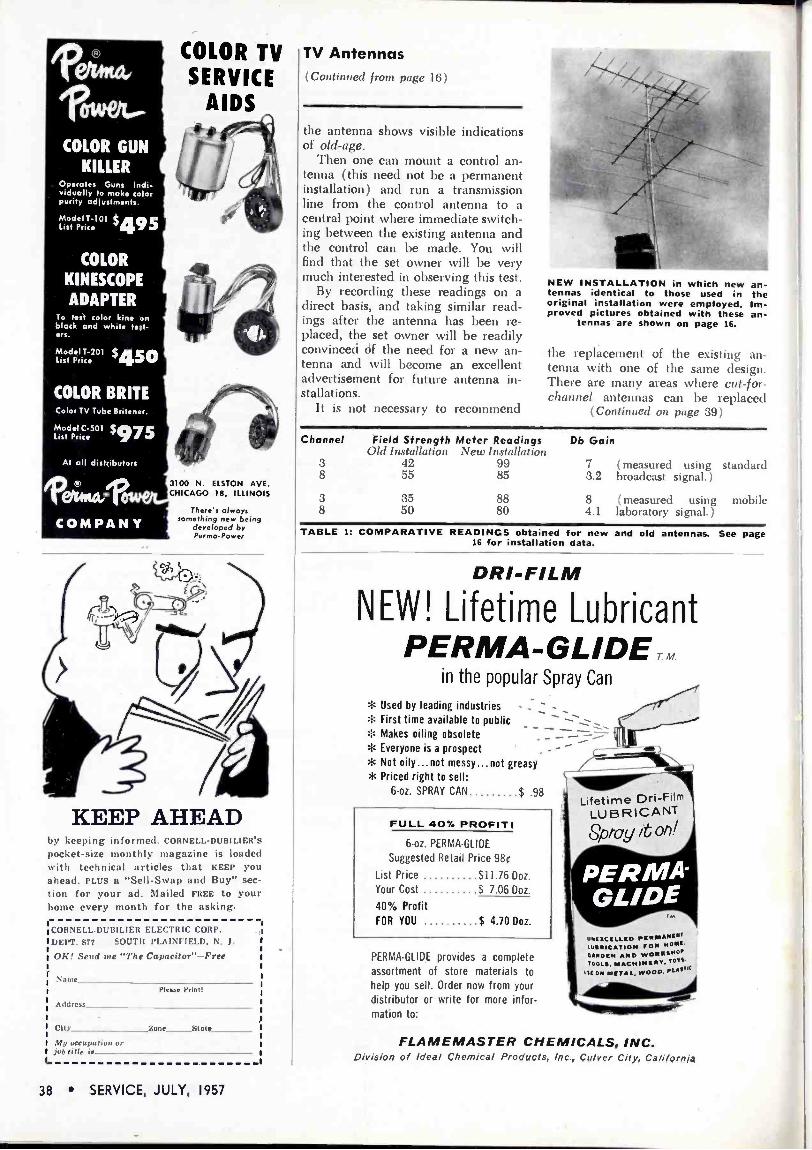
Ilkc
170Wei.-
COLOR GUN KILLER
Operates Guns Indi- vidually to make color purity adjustments.
Model T-101 $495 List Price
COLOR TV SERVICE
AIDS
t r
COLOR
KINESCOPE' ADAPTER
To test color kine on black and while test- ers.
Model T-201 $450 List Price
COLOR BRUTE Color TV Tube Britener. .
Model C-501 ,5975 J' List Price . }
Al all distributors
w of/i. .., COMPANY
N l/D".,
3100 N. ELSTON AVE. CHICAGO 18, ILLINOIS
There's always something new being
developed by Perms -Power
KEEP AHEAD by keeping informed. CORNELL-DUBILIER'S pocket-size monthly magazine is loaded with technical articles that KEEP you ahead. PLUS a "Sell -Swap and Buy" sec-
tion for your ad. Mailed FREE to your home every month for the asking.
CORNELL.DUBILIER ELECTRIC CORP.
DEPT. S77 SOUTII PLAINFIELD. N. 1.
OK! Send me "The Capacitor "-Free
Name Plese Print!
Address
City Zone State
Mu occupation or job title is
L
TV Antennas (Continued from page 16)
the antenna shows visible indications of old -age.
Then one can mount a control an- tenna (this need not be a permanent installation) and run a transmission line from the control antenna to a central point where immediate switch- ing between the existing antenna and the control can be made. You will find that the set owner will be very much interested in observing this test.
By recording these readings on a direct basis, and taking similar read- ings after the antenna has been re- placed, the set owner will be readily convinced of the need for a new an- tenna and will become an excellent advertisement for future antenna in- stallations.
It is not necessary to recommend
NEW INSTALLATION in which new tennas identical to those used in original installation were employed. proved pictures obtained with these
tennas-are shown on page 16.
an- the Im- an-
the replacement of the existing an- tenna with one of the same design. There are many areas where cut -for - channel antennas can be replaced
(Continued on page 39)
Channel
3 8
3 8
Field Strength Meter Readings Old Installation New Installation
42 99 55 85
Db Gain
7 (measured using standard 3.2 broadcast signal. )
35 88 8 (measured using mobile 50 80 4.1 laboratory signal. )
TABLE 1: COMPARATIVE READINGS obtained for new and old antennas. See page 16 for installation data.
DR/-F/LM
NEW! Lifetime Lubricant PERMA-GLIDETM.
in the popular Spray Can
e
* Not oily...not messy...not greasy Priced right to sell:
6 -oz. SPRAY CAN $ .98
Used by leading industries - _ `- First time available to public Makes oiling obsolete _ - Everyone is a prospect'-
FULL 40% PROFIT!
6 -oz. PERMA-GLIDE
Suggested Retail Price 98c
List Price $11.76 Doz.
Your Cost $ 7.06 Doz.
40% Profit FOR YOU $ 4.70 Doz.
PER MA -GL provides a complete assortment of store materials to help you sell. Order now from your
distributor or' write for more infor- mation to:
:N
Lifetime Dri-Film LUBRICANT Spray it on!
PERMA GLIDE
TM
UIucaCILLED PERMANENT LUBRICATION row 00N1. CAMDEN AND woews NOP
100LB, MACHINERY, TOTS.
015 ON METAL. WOOD. PLASTIC
FLAMEMASTER CHEMICALS, INC. Division of /deal Chemical Products, Inc., Culver City, California
38 SERVICE, JULY, 1957

ADVERTISERS IN SERVICE
JULY, 1957
American Television and Radio Co
Amphenol Electronics Corp
Argos Products Co
Atlas Sound Corp
BAK Manufacturing Co
Blonder -Tongue Laboratories, Inc
Bussmann Manufacturing Co
Page
40
32
2
28
31
40
18
Centralah, A Div. of Globe -Union, Inc. 3
Cleveland Institute of Radio Electronics 1
Cornell-Dubilier Electric Corp. Inside Front Cover, 30, 38, 39
Dependable Appliance Parts Co
Electronic Chemical Corp
Erie Resistor Corp
Fast Chemical Products Corp
Flamemaster Chemicals, Inc
39
24
25
24
38
General Cement Manufacturing Co., Div. of Textron, Inc 33
General Electric Co., Electronic Components Div.
Reath Co.
Jensen Industries, Inc
Kesler Solder Co.
Littelfuse, Inc.
P. R. Mallory & Co., Inc.
Perma-Power Co.
Fyramtd Electric Co.
4
23
28
25
13
34
38
17
The Radiart Corp. Inside Front Cover, 30, 38, 39
Radio Corporation of America, Electron Tube Division Back Cover
Raytheon Manufacturing Co 6
John F. Rider Publisher, Inc 35
Service Instruments Corp.
Shure Brothers, Inc
Snyder Manufacturing Co.
28
29
5
Triplett Electrical Instrument Co. Inside Back Cover
University Loudspeakers, Inc
Waage Manufacturing Co
G. F. Wright Steel R Wire Co
Xcelite, Inc.
27
28
22
22
TV Antennas (Continued from page 38)
.~2.
ORIGINAL ANTENNA installation con- sisting of models cut -for -channels; Taco
1850 and 1325.
with an all -channel antenna to pro- vide full coverage of the stations now in the area.
Service Engineering (Continued from page 15)
51.000 worth of electronic gear on hoard.
Besides commercial gear, many boats are equipped with TV sets in- stalled and serviced by Marine Radio. When riding the Pacific waves, TV stations can be picked up when 100 miles out to sea. The Los Angeles area amateur mariner has a choice of the seven TV stations in Los Angeles plus those in San Diego and Santa Barbara.
Audio (Continued from page 37)
before and after adding such a box shield.
Another method is tó add a steel plate approximately ;Ñ" thick between the mechanism and the motorboard.
In most all applications, a pre- amplifier must be used to provide am- plification and equalization; a variable reluctance pickup is lower in output and impedance than crystal and ceramic pickups.
The pickup arm must be changed to accommodate the physical differ- ence in pickups. In most cases, the mounting screws for ceramic and crystal pickups are %" apart and for reluctance pickups they are 's'"" apart. Stylus type will depend on cartridge design: turnorcr, slipunder or turn- around.
The counterbalance spring must provide the correct stylus force. This force should be 7 to 9 grams on three and four -speed changers, or 5 to 7 grants on -15-changers.
FOOLPROOF COIN VAULTMETER
Maximum Coin Security
Shake -Proof -
Trouble -Free ifAl Coin Chute
Simplicity in Mounting
Variable Timing Unique Design
25t' Coin Meter for automat cally timing ap- pliances. Made of 14" gauge steel-all internal parts cadmium plated.
Solves installation problem by having the back panel removable to speed up and simplify mounting. No die cast parts, drive gears, or knobs to wear out. Being 14" gauge steel throughout entire case, makes it as burglar- proof as is possible.
Can be used on all 220 -volt model dryers. Available with 60 -min. or 45 min. clocks-
timing cycles may be halved. Timing will service most all automatic washers, dryers, wringer washers, as well as Television pro- grams of 30 minutes duration.
will automatically throw out any undersized coins by a patented coin arrestor and slot, as suring owners of all monies due them.
Overall dimensions: 33" x 81A".
Model 400 with Coin Vault, list price $26.25
Model 500 with Cash Receptacle only, list price $22.80
Some distributorships still available.
The DEPENDABLE APPLIANCE PARTS CO.
4502 Hough Ave., Cleveland 3, Ohio
v.d=w.,.,
PILE UP PROFITS by speeding up your service. Read CORNELL-DUBILIER'S pocket-size monthly magazine loaded with short-cuts and aids to servicing. PLUS a "Sell -Swap -Buy" section for your ad. Mailed FREE to your home every month for the asking.
L
COI12 ELL-DUBILIER ELECTRIC CORP. DEPT. Si? SOUTH PLAINFIELD. N. 3
010 Send me "The Capacitor"-Free
Name
Address
City Zone Stale
PI,u. Print!
My occupation or job title is
SERVICE, JULY, 1957 39

S H AV- PA K
W, LOW PRICE!
- :i %;
SHAVE IN THE COMFORT
OF YOUR CAR,
Boat or Plane!
t':-- Specially Designed for Operating Standard AC.
$663 Electric Shavers in
Plugs into DEALER Automobiles, Buses, Cigarette Lighter PRICE Trucks, Boats, and
Receptacle on Dash List Price Planes. 59.95
TYPE
INPUT
D.C.
VOLTS
A.C.
OUTPUT 60 cecLEs
OUTPUT
WATTAGE
Dealer Price
6SPB
12SPS
6
12
115 volts
115
15
15 56.63 $6.63
pT MIGHTY MIDGET fottet64INVERTER WITH GREATER OUTPUT
DICTATE REPORTS ACCURATELY -PROMPTLY!
make your car, boat or plane a `trolling office"
with ATR INVERTERS
Woudettotalt
Plugs into Cigarette Lighter
Receptacle on Dash (75, 30 13 $
/ T up
- PRICE.; LIST PRICE 519.95
ATR INVERTERS .. . especially designed for operating standard 110 volt A. C.
DICTATING MACHINES TAPE RECORDER ELECTRIC RAZORS WIRE RECORDERS
for changing your storage battery current to A. C.
ELECTRICITY
in your own car!
INPUT A.C. D.C. OUTPUT OUTPUT DEALER
TYPE VOLTS 60 CYCLES WATTAGE PRICE 12-D M E 12 Ila 40.50 513.30 12URHr 12 115 150-175 59.97 Inverters available for 6. 12. 28. 32, 110 a 220 D.C.
Input operation.
See 9~r 1eaen os wale óactesy today ,.
,,1A AUDI( dal Garrefdet (.r/os..v t'ar pAM TeorvKInut r Rlrrn en
1
2..6pP..a45*.1181 SAINT PAUL I MINNESOTA-U.1. A.
PERSONNEL L. F. IIoLLERAN has been appointed manager, distributor products of the RCA electron tube division. JOHN B. FARESE is now manager of entertainment tube products, and C. E. BuRNETT has become manager of industrial tube prod- ucts in the tube division.
Holleran
o o o
Farese
\V.\RREN IIowE has been appointed mar- ket analyst of the Belden Manufacturing Co., Chicago.
o a o
JOHN \IESSERSCHMITT, formerly in the renewal tube sales division of Amperex Electronic Corp., 230 Duffy Avenue, Ilicksville, L. I., has been made assistant to Fn %NE R NDALL, vice president and general sales manager.
O o o
ROBERT BEEBE has been named head of the communications antenna sales divi- sion of Ward Products, a division of Gabriel Co.
Te
Beebe Burroughs
Louis R. BURROUCHS has been elected vice president for broadcast and record- ing equipment at Electro -Voice, Inc., Buchanan, Mich. Burroughs, former E -V chief engineer, has been with E -V since its inception in 1927.
O o o
SAISI NV. 111CIIER has been promoted to assistant general sales manager -merchan- dising of the United Motors System divi- sion of General Motors Corp., Detroit 2.
o o o
SYDNEY \V. MORRELL is now vice presi- dent in charge of public relations of International Telephone and Telegraph Corp., 67 Broad St., New York 4, N. Y.
O o o
ROBERT I. MENDELS hás been elected president of Electronic Devices, Inc., 429 12th Street, Brooklyn, N. Y.
e e o
HERIIERT A. BODKIN has been appointed sales manager of Electrovox Co., Inc., 60 Franklin St., East Orange, N. J.
8 NEW fl -BT
PRODUCTS ... just a few of the many
new B -T precision engineered products
FIELD STRENGTH METER Model FSM-1
A portable precision instrument for accurate measurement of RF signals. Continuous tuning from 54 mc to 216 mc covering VHF -TV, FM, mobile, air- craft, ham, industrial and CD. Use of B -T UHF converter extends range to entire UHF band. $310 net
3 MASTERLINE CRYSTAL - CONTROLLED CONVERTERS
Model MVC: Hi -to -Lo channel VHF converter.
Model MLC: Lo -to -Lo channel VHF converter.
Model MUC: UHF to VHF converter.
List $300 Each Extremely stable, self -powered with two matched 75 ohm outputs. All channel VHF mixing net- work. flat within 1/2 db over full 6 mc output. For color and black and white TV.
4 INDOOR TV SYSTEM TAPOFFS Easy to install, matched low cost tapoffs Model TO1-75: single isolated tapoff for recessed mounting. For RG-1 1 /U or RG-59/U, with 75 ohm jack. List $4.50 Model 101-300: has 300 ohm terminals.
List $4.50 Model T02-75: two 75 ohm outlets from RG-1 1 /U or RG-59/U cable. List $9.00 Model TO2-300: two 300 ohm isolated outlets from RG-11 /U or RG-59/U cable.
List $9.00 sold by electronic parts distributors for further information use coupon below
BLONDER -TONGUE LABS, INC. 9-25 Ailing Street, Newark 2, N. J. S-7
Please send me literature covering: O Field Strength Meter Masterline Converters
O Indoor TV System Tapoffs
Name
Address
Zone_state -._.._._
40 SERVICE, JULY, 1957

performance matched test equipment
for black and white
and ALL tv
basic
.
_CH U EGTMUU
1
MODEL 631 VOM-VTVM two in one tester for 100% service-VOM covers 90% of your usage, battery operated VTVM available for the other 10% when you need it. 564.50
=1 o ,. Ire,,.r tr,,,..,,r.,,
-I-
631 630 -NA Combinotion For Best Testing
V0-M-VTVM Around the lob, Production line
or Bench
T
630 The Popular AllPu, pose
V.O.M
fundamental 4.
essential
00 _ o ... 'o®.::
--¡ li,a"!-rrri1ti ., .
MODEL 3423 four in one-mutual conductance tube tester, transistor tester, germanium diode tester, selenium rectifier tester -checks for accuracy as circuit demands depending on the tolerance of the circuit. The patented circuit for the tube testing em- ploys actual signal (4KC) for grid and DC bias voltage making it independent of line voltage hum. It also has a complete coverage of all tube types-six plate voltages (includ- ing 0-10 variable). Micromhos scales read 0-1,800, 0-6,000, 0-18,000 and 0-36,000. Leak- age measured directly on meter 0-10 meg- ohms. 5199.50
TRIPLETT
I
3i
to tonr, /+{ .cti` ,.
- ---_
MODEL 3441-A three in one scope-oscillo- scope, peak -to -peak meter, audio oscillator- essential for more than 50% of your Black and White Servicing-all Color Servic- ing. 10 my sensitivity. 4.5 me band- width. 5249.50
These three units provide the ideal basis for the complete servicemen's test setup for black and white and color TV. You will want to consider also Model 3438 Dot Generator, Model 3439 Color Bar Generator, Model 3434-A Sweep Genera- tor and other Triplett units.
ELECTRICAL INSTRUMENT COMPANY BLUFFTON, OHIO
--T
630-A ¡ 310 A Good lab and I The Smallest Production line Cc mplete V -O -M
VOM with Switch
-r
630-T For Telephone
Service
T T
666-HH Medium Size
for Field Testing
625 -NA The First V -0.M
with 10,000 Ohms/Volt AC
,_tea#:
666-R Medium Size
with 630 Features
1

r
Jt4
IN THE
1
d
FREE OF EXTRA CHARGE WHEN YOU BUY RCA TOP-QUALITY RECEIVING TUBES!
Here's practical information on Color TV. Clearly written by John R. Meagher, RCA's nationally recognized authority on TV servicing and originator of the famous RCA Pict -O -Guide for black -and -white TV. It's profusely illustrated with full -color photos taken from an operating color -TV receiver. Step-by-step instructions and diagrams provide many labor - and time -saving short-cuts for profitable color -TV servicing. Build up your share of the dynamic color -TV service market with the new PICT -O -GUIDE. Get your copy from your RCA tube distributor...today!
RECEIVING TUBES RADIO CORPORATION OF AMERICA
Electron Tube Division Harrison, N. J.
Speeds up, simplifies installation, adjustment, and
servicing of colortv receivers
Saves time in localizing color -tv troubles
Profusely illustrated in full color, and monochrome
Sturdily bound in lieflat, multiple -ring covers
NEW COLOR -TV PICTOGUIDE CONTAINS SECTIONS ON:
Color Mixing RCA
Compatible Color TV System Purity Convergence
GrayScale Tracking Color Operating Controls Antenna Considerations RFIF Bandpass Alignment Color Test Equipment Color -Bar Patterns Troubleshooting -
Signal Tracing Interference "Green Stripe" Test Signals