Embed Size (px)
Citation preview

www . El
ectric
alPar
tMan
uals
. com

(}T' Core-and-Coil Transformers
offer maximum flexibility
e Machine Tool Type IP; 50 VA- 5 kVA ...................................... Page 4 A Featuring a new listing of all-copper windings ...,
• Control and Power Type IP; 25 VA - 3 kVA ................................. Page 6 • Control and Power Type ML-C; 5 kVA - 25 kVA ............................. Page 10 e Type HV High Voltage; 1 kVA - 5 kVA ...................................... Page 11 e Power Type QL-C; 30 kVA - 500 kVA ....................................... Page 12 e Type VB Epoxy-Cast; 5 kVA- 50 kVA ...................................... Page 14 • Volt-pac® Variable Autotransformers; 560 Volts and below ................... Page 16
Broad Selection for Power and Control Applications
General Electric offers a complete line of open, dry-type, core-and-coil transformers for a wide range of power and control applications. Installation flexibility is provided by a choice of mounting types. Units are available for mounting either integrally within equipment cabinets or separately in individual enclosures. In addition, General Electric has combined the inherent advantages of drytype transformers-light weight, compact size, fire resistance-with a broad range of construction types and termination arrangements. This provides added flexibility for application within the customers' equipment. In larger ratings, many preferred modifications and accessories are offered.
Characteristics
• SOUND LEVELS
Core-and-coil sound levels when mounted in a suitable enclosure
Above kVA L2kV L2kV
0-9 40 45 10-50 45 50 5l-l50 50 55
151-300 55 58 301-500 60 6 0
•Measured per ANSI-C89. I 1961-2.7.3-4, NEMA ST-20 1972
• OVERLOAD CAPABILITY (For transformers 5 kVA and larger)
General Electric dry-type transformers rated 5 kV A and larger have inherent overload capability to be used without affecting normal life expectancy. Transformers below 5 kVA should not be overloaded, since their compact size does not provide the mass necessary to dissipate additional heat created by overloads.
Transformers are capable of long service life if loaded in accordance with the ANSI loading guide shown in the following table.
Permissible once daily overloads with normal life maintained
'!, 162% NPR 185% NPR 200% NPR
1 138% NPR 148% NPR 152% NPR 2 123% NPR 128% NPR 133% NPR 4 113% NPR 115% NPR 118% NPR
6 106% NPR 107% NPR 108% NPR
NPR. Nameplate rating.
• TEMPERATURE CLASS
Insulation systems used in General Electric QHT transformers are specifically designed to optimize size, weight. performance and reliability.
The design life of transfom1ers having different insulation svstems is the same, since the allowable temperature rise of
2
any insulation system is predicated on providing long life. The lower temperature systems are designed for the same long life as higher temperature systems. Type IP units below 250 VA have a 105 C insulation system, 250 VA and above utilize a 185 C system.
Industry standards classify insulation systems in accordance with the rating system as follows:
INSULATION SYSTEM CLASSIFICATION
Industry Standards
General Electric QHT dry-type core-andcoil transformers meet applicable UL, CSA, NEMA, ANSI and IEEE standards.
Type IP transformers are UL Listed (File E2739) through 5 kVA and have CSA component certification (File 3272) through 3 kVA. Others are UL component recognized and CSA component certified. With considerable emphasis being placed on transformer applications by the Federal Occupational Safety and Health Act (OSHA), UL Listing and recognition is especially significant.
0
0
0
www . El
ectric
alPar
tMan
uals
. com

Industrial Control Transformers, Type IP for Machine Tool and Control Applications
600 volts and below, 50 VA-SkVA- UL Listed (File E2739) and CSA Component Certified (File 3272)
3 www . El
ectric
alPar
tMan
uals
. com

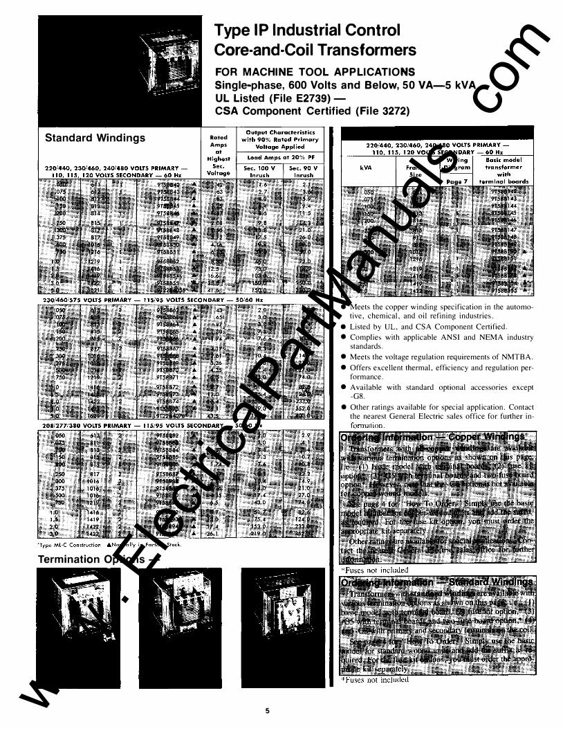
Type IP Industrial Control Core-and-Coil Transformers FOR MACHINE TOOL APPLICATION S Single-phase, 600 Volts and Below, 50 VA- 5 kVA UL Listed (File E2739)-CSA Component Certified (File 3272)
Description Core-and-coil transformers for
machine tools are used to provide voltage to control devices in applications where regulation and minimum panel space are important. Four different terminal arrangements are available:
I. Basic model transformers with terminal boards.
2. Basic model with secondary fuse kit shipped separately and installed by customer.
3. Basic model transformers with twofuse board option.
4. Transformers with terminals on coil.
Designs comply with the electrical requirements of ANSI C89. 1 / NEMA ST 1-4 for machine tool transformers. All Type IP models are UL Listed (File E2739) and CSA Component Certified (File 3272), except the G5 terminal arrangement.
Type IP units below 250 VA have a 105 C insulation system, 250 VA and above utilize a 185 C system.
Installation flexibility, light weight and compact size provide added flexibility of application. The General Electric Type IP transformer offers designers a broad selection for control applications.
Selection It is important that full consideration
be given to the continuous and overload characteristics of relay coils, solenoid coils, starter coils, and all other types of components in the system. Complete information of this type will assist the designer in selecting the smallest and least expensive transformer for the application.
First, determine the primary and secondary voltages and frequency needed. Second, calculate the maximum continuous current required to power the load. Third, calculate the maximum inrush current caused by the load. Fourth, from the tables on pages 5, locate the lowest kVA rated transformer that will supply the inrush and continuous current.
For those applications where specific regulation requirements must be met, regulation curves for selected Type IP models are shown on Pages 8 and 9.
How to Order
T o d e t e r m i n e c o m p l e t e m o d e l number:
First, select the basic model number. For example, specify model 9T58B50 if you want a unit with a 230/460 volt primary, 115 volt secondary, operating at 60 hertz and rated . 500 k VA.
Second, select the terminal arrangement desired. Assuming the transformers you need are rated 230/460 volts primary, l l5 volts secondary, 60 hertz, . 500 k VA; here's how you differentiate between the various terminal arrangements that are available:
• Basic model transformer with terminal board - order by model number, i.e. 9T58B50.
• Basic model transformer with terminal boards and a secondary fuse kit -order the basic model number and the corresponding fuse kit number as follows: for kVA ratings from .050 thru 1.5, order 9T58Pl ; for 2, 3 kVA units, order 9T58P2. (Note: fuses not included)
4
• Basic model with terminal boards and two-fuse board - add -G5 suffix to the b a s i c m o d e l n um b e r , i . e . , 9T58B50G5.
• Transformer with terminals on coiladd -G8 suffix to the basic model number, i. e. , 9T58B50G8.
Copper Windings In a number of applications and indus
tries today, there are requirements for industrial control transformers with copper windings.
General Electric's current published line of core-and-coil transformers are built with copper or aluminum windings as specified by the design engineer to provide a product with the optimum combination of cost, weight, electrical and thermal characteristics for economical and reliable service in the broadest range of applications.
For those applications where copper is mandatory, General Electric now offers a new line of all-copper winding models. (See page 5). For special requirements, forward your complete specifications and needs to the nearest General Electric sales office for a prompt response.
Dimensions and Weights Dimensions and weights of all Type IP
units listed in this publication are given on page 7. To find specific dimensions and weights, note frame size of selected model and refer to page 7.
www . El
ectric
alPar
tMan
uals
. com
Standard Windings
Termination Options-
Type I P Industrial Control Core-and-Coil Transformers
FOR MACHINE TOOL APPLICATIONS Single-phase, 600 Volts and Below, 50 VA-S kVA UL Listed (File E2739) -CSA Component Certified (File 3272)
Rated Amps
5
e Meets the copper winding specification in the automotive, chemical, and oil refining industries.
• Listed by UL, and CSA Component Certified.
e Complies with applicable ANSI and NEMA industry standards.
• Meets the voltage regulation requirements of NMTBA.
• Offers excellent thermal, efficiency and regulation performance.
• Available with standard optional accessories except -G8.
e Other ratings available for special application. Contact the nearest General Electric sales office for further in-
www . El
ectric
alPar
tMan
uals
. com

Type IP Industrial Control Core-and-Coil Transformers FOR CONTROL AND POWER APPLICATIONS Single-Phase, 600 Volts and Below 25 VA-3 kVA UL Component Recognized (File E2739)
DESCRIPTION General Electric control transformers for panelboard ap
plications have the same basic construction as the machine tool transformers described on previous pages of this bulletin. However, they do not have the same regulation characteristics. They do meet NEMA specifications for specialty transformers.
Panelboard transformers are available with two types of terminal arrangements - "leads out," and "terminal board." Leads-out construction is designed for use in equipment where limited space is a problem. All leads are permanently identified and are located as shown on the nameplate wiring diagram. Terminal board construction is designed for panel wiring. Here too, terminals are identified and located in accordance with the diagram stamped on the terminal board.
Unlike machine tool transformers, panelboard transformer secondaries can be hooked up in series-multiple connections. Transformers rated 120/240 volts can be connected for 120 volts, 240 volts, or 240/120 volts, three-wire.
Ordering Information
To specify the terminal arrangement you want, simply order by model number. The 9T58B- ''2000 Series'' identifies the basic model number with terminal boards, while the 9T58B- "1000 Series'' identifies units having primary and secondary leads out.
Outline Drawings
TOP SIDE BOTTOM
For Frame Sizes 609, 611, 612, 613, 811. 813, 814, 815, 817
TOP SIDE BOTTOM
---4--+ +
+ +
"---('-
-
For Frame Sizes 1016,1216,1219, 1416, 1419, 1422
END
0 OLESFOR FTING
l I ------- 8 MAX - --4'12 SlOTS FORMTG
SIDE
---- �. ----,-�, ��I,
:II ,q, I 'II !Ill '9 I ,
-- _, Jf---+ ---- A MAX -----�
BASIC MODEL WITH TERMINAL BOARD
END SIDE
D L-- F --.-; � 8 MAX ::::__j R1�F
LEADS OUT MODEL
For Frame Size 1621 .&Normally in Factory Stock.
6 *These voltages at reduced capacity www .
Elec
tricalP
artM
anua
ls . c
om

Type IP Core-and-Coil Transformers Wiring Diagrams
Dimensions and Weights
H3 H5 Hi H2i.J t ........... IIIJ 1"1'1'"'"'"1
X4 X3 X2 X I Diagram 6
HI HZ
LJ PROTECTIVE DEVtCE IF REQUIRED
,rrl,l PROTECTIVE DEVICE If REQUIRED
IXI IXl lXI X 4 X2 X 3 XI X-4 XZ X3 XI X4 X2 X3 XI
Diagram 1 Diagram2 Diagram3 Diagram4 DiagramS
7 www . El
ectric
alPar
tMan
uals
. com
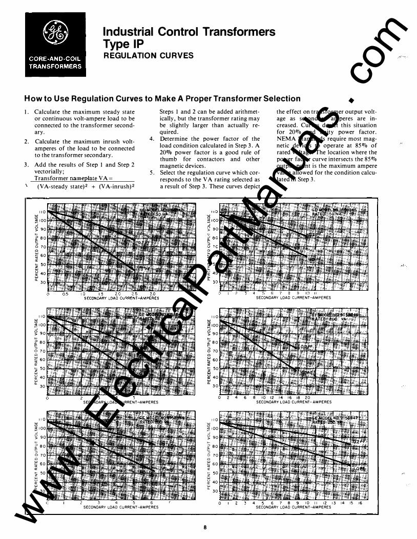
Industrial Control Transformers TypeiP REGULATION CURVES
How to Use Regulation Curves to Make A Proper Transformer Selection
1. Calculate the maximum steady state or continuous volt-ampere load to be connected to the transformer secondary.
2. Calculate the maximum inrush voltamperes of the load to be connected to the transformer secondary.
3. Add the results of Step 1 and Step 2 vectorially;
\ Transformer nameplate VA=
(V A-steady state)2 + (V A-inrush)2
11 0 "" "' �100 __J
§; 90 >-
:::> 80 � 0 70 0 � 60 a:: :z 50 "" � 40 "" o._
w "'
30
110
;! 100 __J
� 90 >-
t_ 80 ':.; 0 70 0
� 60 a:: :z 50 w
� 40 w o._ 30
2
Steps 1 and 2 can be added arithmetically, but the transformer rating may be slightly larger than actually required.
4. Determine the power factor of the load condition calculated in Step 3. A 200Jo power factor is a good rule of thumb for contactors and other magnetic devices.
5. Select the regulation curve which corresponds to the VA rating selected as a result of Step 3. These curves depict
the effect on transformer output voltage as secondary amperes are increased. Curves depict this situation for 20% and unity power factor. NEMA Standards require most magnetic devices to operate at 85% of rated voltage. The location where the power factor curve intersects the 85% output point is the maximum ampere value allowed for the condition calculated in Step 3.
II SECONDARY LOAD CURRENT-AMPERES
110 "" �100 'J � 90
� 80 >-:::> 0 70 0 � 60 a: !Z 50 "" a! 40 "" o._ 30
0 2 4 6 8 10 12 14 1 6 18 20 SECONDARY LOAD CURRENT-AMPERES SECONDARY LOAD CURRENT-AMPERES
II 0 110 w w "' ;!100
__J
"' ;!100 __J
§; 90 §; 90 >- >-� 80 t_ 8 0 >-::J ::J 0 70 0 70 0 0
� 60 � 60 a:: a::
� 50 ,_ 50 z "" w
� 40 � 40 w "" o._ CL 30 30
0 2 3 4 5 6 0 3 4 5 6 7 8 9 10 II 12 13 14 15 16 SECONDARY LOAD CURRENT-AMPERES SECONDARY LOAD CURRENT-AMPERES
8 www . El
ectric
alPar
tMan
uals
. com

UJ "
;g, d >I >--::> "->--::> 0
§ <I a:
>--z UJ u a: UJ "-
UJ "
0
B . > 100 >-::> � ::> 0
� a: !Z UJ u a: UJ "-
UJ " �II 0
>r >--::> "->--::> 0
§ <I a:
>--z UJ u a:
UJ a_
UJ " �II d > 100 >--::> "->--::> 0
§ <I a:
>--z UJ u a:
UJ "-
3 6 9 12 15 18 21 SECONDARY LOAD CURRENT-AMPERES
I 28 SECONDARY LOAD CURRENT-AMPERES
UJ "'
j9: c5 > 100 >-::> ">-::> 0
§ <I a:
>z UJ u a: w "-
24 27
9
UJ " iS: 110 d > 100 >--::> "- 90 >--::> 0 80
� 70 a: !Z 60 UJ u a: UJ "-
UJ "
j9: d >I >-::> ">-::> 0
� a:
>z UJ u a: UJ "-
UJ "
j9: d 1 10
>roo >--::> "- 90 >--::> 0 80 § 70 <I a:
>-- 60 z UJ u a: 0 UJ "-
UJ " � 110 0
>roo � 90 >--::> 0 0
80 UJ
� 70 a:
>-- 60 z UJ u a: UJ
"-
50
64 112 SECONDARY LOAD CURRENT-AMPERES
100 150 200 SECONDARY LOAD CURRENT-AMPERES
250
www . El
ectric
alPar
tMan
uals
. com

Type ML-C Industrial Control Core-and-Coil Transformers FOR CONTROL AND POWER APPLICATIONS
Single Phase, 600 Volts and Below, S.Q--25 kVA UL Component Recognized (File E2739- and E79145)
Description Core-and-coil Transformers of the
ML-C construction type for control and power applications are designed with kV A and voltage ratings to tie in with system and equipment ratings.
All units meet the requirements of ANSI/NEMA specifications for specialty transformers.
The ML-C frames are designed for universal mounting; any side of the transformer can be mounted on a floor, wall, or ceiling.
The leads out construction is designed for panel wiring use in equipment where limited space is a problem. All leads are identified in accordance with the nameplate wiring diagram.
Dimensions and Weights
A.Normally in Factory Stock.
Outline Drawings END SIDE �-��-n;i:�
w;lll""' ,w _ _U_ .-E I
6' 111 11]1 �0� ' �12 SLOTS FORMTG 10-- -- �
BASlC II.OO€L WITH TERMINAL BOARD
END SIDE
LEADS OUT M ODEL
For Frame Sizes 1621,1622,1625,1626,1922,1926,1932
Wiring Diagrams
"L5ZJ lXI
X 4 X2 X 3 Xt
Diagram3
1 ... .... r.r.J IXl
X4 X 2 X 3 X I
Diagram4
Series Multiple Connection Transformers rated 120/240 volts can be connected for 120
volts, 240 volts, or 120/240 volts three wire. Units rated 240/480 volts can be connected for 240 volts or 480 volts.
10 www . El
ectric
alPar
tMan
uals
. com
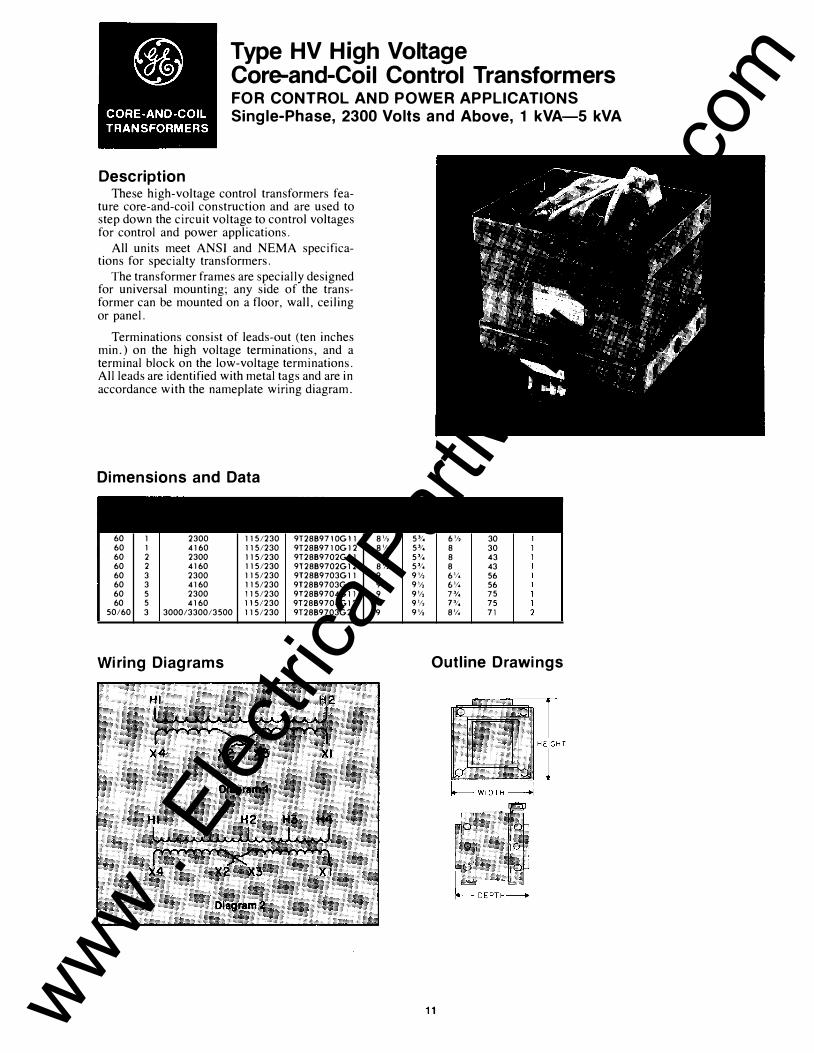
Type HV High Voltage Core-and-Coil Control Transformers FOR CONTROL AND POWER APPLICATIONS Single-Phase, 2300 Volts and Above, 1 kVA-5 kVA
Description These high-voltage control transformers fea
ture core-and-coil construction and are used to step down the circuit voltage to control voltages for control and power applications.
All units meet ANSI and NEMA specifications for specialty transformers.
The transformer frames are specially designed for universal mounting; any side of the transformer can be mounted on a floor, wall, ceiling or panel.
Terminations consist of leads-out (ten inches min. ) on the high voltage terminations, and a terminal block on the low-voltage terminations. All leads are identified with metal tags and are in accordance with the nameplate wiring diagram.
Dimensions and Data
60 1 2300 1151230 9T288971 OG 11 60 1 4160 1151230 9T288971 OG 1 2 60 2 2300 1151230 9T28B9702G 1 1 60 2 4160 1151230 9T28B9702G 12 60 3 2300 115/230 9T28B9703G 11 60 3 4160 115/230 9T2889703G 12 60 5 2300 1151230 9T2889704G 1 1 60 5 4160 1151230 9T28B9704G 1 2
50/60 3 3000/3300/3500 1151230 9T2889703G2
Wiring Diagrams
81/:;r 53! .. 6,/, 30 81/:;r 53! .. 8 30 8,/, Sl! .. 8 43 81/:;r 53! .. 8 43 9 91/:;r 61! .. 56 9 91/:;r 61/4 56 9 91/:;r 7% 75 9 91/:;r JlJ .. 75 9 9,/, 81/ .. 71
Outline Drawings
11 www . El
ectric
alPar
tMan
uals
. com

Type QL-C Core-and-Coil Power Transformers
FOR POWER APPLICATIONS
Three-Phase, 600 Volts and Below 30-500 kVA UL Component Recognized
Application General Electric's Type QL-C core-andcoil power transformer has all-purpose application as a source of distribution power, lighting, or step-down voltage for indoor and outdoor switchboards, panels, or motor control centers. This core-and-coil is intended to be mounted within a suitable enclosure for use in convection-cooled or forced air cooled equipment.
Electrical clearance around the coreand-coil transformer must be in accordance with NEC 373-11. Free circulation of air is essential for the proper operation of all dry-type transformers. Provisions for the entrance of cooling air should be below the lowest part of the core, and provisions for the egress of the heated air should be above the highest part of the core. For each 100 kV A of transformer rating, the inlet and outlet opening should each have a net clear area of one square foot, except that each net area shall never be less than one-half square foot for 50 kV A and below.
Features All QL-C core-and-coil power transformers are recognized under the component program of Underwriter Laboratories, Inc. With considerable emphasis
being placed on transformer application by the Federal Occupational Safety and Health Act (OSHA), UL recognition is especially desirable.
These three-phase units are available in ratings from 30 kVA through 500 kVA. Units are rated 60 hertz and are available in the most popular voltages required by equipment manufacturers.
UL Listed 220 C insulation system (150C rise).
High temperature insulation materials with proven reliability through life testing per Standard IEEE-259.
Meets UL thermal overload test of 200 percent of rated current for one-half hour. Meets ANSI C57 .12 loading guide.
Termination location and spacing are convenient for cable connection and permit use of low-temperature cable.
Provided with rigid base to facilitate easy handling of unit.
Universal taps: ( 4) 2 Yz percent below normal and (2) 2 Yz percent above normal.
12
Ratings and Data
60 hertz, 480V- 208Y/l20- (6) 2'12% taps, 2 above and 4 below 480 volts
60 hertz, 600V- 208Y/l20- (6) 2112% laps, 2 above and 4 below 600 volts
Special Voltage In addition to the three-phase voltage ratings listed under Ratings and Data, other ratings are available as follows:
480V primary-480Y /277V secondary 240V primary-208Y /120V secondary 208V primary-480Y /277V secondary
Single-phase transformers are available in ratings from 37.5 through 167 kV A; with 240 x 480- or 600-volt primary, and 120/240-volt secondary.
Performance Data
*Design sound level in a suitable enclosure.
www . El
ectric
alPar
tMan
uals
. com
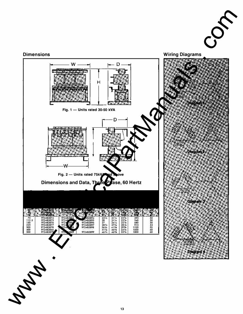
Dimensions W iring Diagrams
Fig. 1 -Units rated 30-50 kVA
Fig. 2-Units rated 75kVA and above
Dimensions and Data, Three-Phase, 60 Hertz
75 9T24B3874 9T24B3884 9T24B3894 23V2 31'/4 22Ve 395 50 112.5 9T24B3875 9T24B3885 9T24B3895 28 31'/4 22Ve 540 50 150 9T24B3876 9T24B3886 9T24B3896 27 341/4 227/e 680 50 225 9T24B3877 9T24B3887 9T24B3897 283/4 373,4 28Ve 915 55 300 9T24B3878 9T24B3888 9T24B3898 363,4 415fs 29:Ye 1220 55 400 9T24B3866 41Ve 465/e 33Ve 1600 60 500 9T24B3879 9T24B3889 9T24B3899 463/4 465fs 33Ve 1800 60
13 www . El
ectric
alPar
tMan
uals
. com
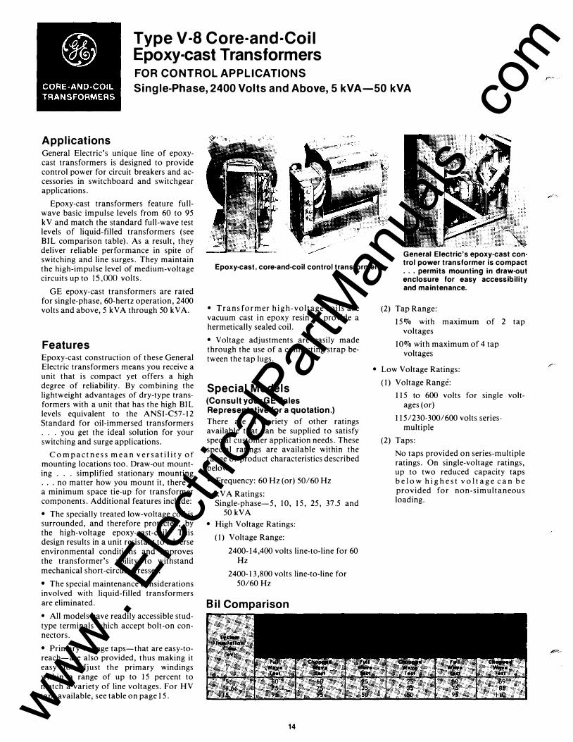
Type V-8 Core-and-Coil Epoxy-cast Transformers FOR CONTROL APPLICATIONS
Single-Phase, 2400 Volts and Above, 5 kVA-50 kVA
Applications General Electric's unique line of epoxycast transformers is designed to provide control power for circuit breakers and accessories in switchboard and switchgear applications.
Epoxy-cast transformers feature fullwave basic impulse levels from 60 to 95 kV and match the standard full-wave test levels of liquid-filled transformers (see BIL comparison table). As a result, they deliver reliable performance in spite of switching and line surges. They maintain the high-impulse level of medium-voltage circuits up to 15,000 volts.
GE epoxy-cast transformers are rated for single-phase, 60-hertz operation, 2400 volts and above, 5 kV A through 50 kV A.
Features Epoxy-cast construction of these General Electric transformers means you receive a unit that is compact yet offers a high degree of reliability. By combining the lightweight advantages of dry-type transformers with a unit that has the high BIL levels equivalent to the ANSI-C57-12 Standard for oil-immersed transformers . . . you get the ideal solution for your switching and surge applications.
Co m p a c t n e s s m e a n v e r s a t i l i t y of mounting locations too. Draw-out mounting . . . simplified stationary mounting . . . no matter how you mount it, there is a minimum space tie-up for transformer components. Additional features include:
• The specially treated low-voltage coil is surrounded, and therefore protected, by the high-voltage epoxy-cast-coil. This design results in a unit resistant to adverse environmental conditions and improves the transformer's ability to withstand mechanical short-circuit stresses.
• The special maintenance considerations involved with liquid-filled transformers are eliminated.
• All models have readily accessible studtype terminals which accept bolt-on connectors.
• Primary voltage taps-that are easy-toreach-are also provided, thus making it easy to adjust the primary windings within a range of up to 15 percent to match a variety of line voltages. For HV taps available, see table on page 15.
Epoxy-cast, core-and-coil control transformer
General Electric's epoxy-cast control power transformer is compact ... permits mounting in draw-out enclosure for easy accessibility and maintenance.
• Trans former h i g h- voltage coils are vacuum cast in epoxy resin to provide a hermetically sealed coil.
• Voltage adjustments are easily made through the use of a connecting strap between the tap lugs.
Special Models (Consult your GE Sales Representative for a quotation.)
There are a variety of other ratings available that can be supplied to satisfy special customer application needs. These special ratings are available within the range of product characteristics described below.
• Frequency: 60Hz (or) 50/60Hz
• kVA Ratings: Single-phase-5, 10, 15, 25, 37.5 and
50 kVA
• High Voltage Ratings:
(1) Voltage Range:
2400-14,400 volts line-to-line for 60 Hz
2400-13,800 volts line-to-line for 50160 Hz
Bil Comparison
14
(2) Tap Range:
150Jo with maximum of 2 tap voltages
10% with maximum of 4 tap voltages
• Low Voltage Ratings:
(1) Voltage Range:
115 to 600 volts for single voltages (or)
115/230-300/600 volts seriesmultiple
(2) Taps:
No taps provided on series-multiple ratings. On single-voltage ratings, up to two reduced capacity taps b e l o w h i g h e s t v o l t a g e c a n b e provided for non-simultaneous loading.
www . El
ectric
alPar
tMan
uals
. com

c
c
c
c
c
Mechanical and Electrical Data
50 kVA. see figure number 23
: 50 60 hertz-see Fig. 21. · 277 volts-refer to factory for outline dimensions.
" See table for HV tap connections.
Wiring Diagrams
Ffg.13 Fig.16
·Fig.14 Fig.17
LJGJ.
Fig.19
15
Dimensions
Fig. 20 5 kVA, single-phase
Fig. 21
1 o, 15 kVA, single-phase
Fig. 22
·� 18 �
I '' ' '6'e
4Sio'' ,,,.., ..
25 kVA single-phase
I m Q � o ,
� i ·��:""
�'
- 14118" -
L 263/S"MAX
13/16"• 1118" 4 SLOTS FOR MOUNTING
Fig. 23
- 131/2" - I r- 161!2"MAX. -'
20 II/16"MAX-
37.5, 50 kVA single-phase
+71h% 1-2 (1) ±71/2 N�INAL 2..,_3
-71!a01<> 3-4
+S% 1- 2 +21/a% 2 -- 3
(2) ±21/z NOMINAL 3- 4 -21h% 4- 5
- 5% 5-6
NOMINAL 1 ...... 2 -21h% 2.-3
(4) -21/z -- 5% 3 ..,-- 4
-7112% 4- 5 -100/c. 5-6 www .
Elec
tricalP
artM
anua
ls . c
om
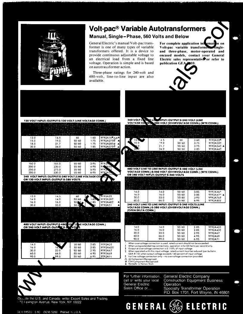
Volt-pac® Variable Autotransformers Manual, Single-Phase, 560 Volts and Below
General Electric's manual Volt-pac transformer is one of many types of variable transformers offered. It is a device to provide continuous adjustable voltage to an electrical load from a fixed line voltage. Operation is simple and is based on autotraiisformer action.
For complete application information on Volt-pac variable transformers, singleand three-phase, motor-operated and encased models, contact your General Electric sales representative or refer to publication GEA-8110.
Three-phase ratings for 240-volt and 480-volt, line-to-line input are also available.
16.0 33.0 66.0
240 VOLT LINE TO LINE INPUT: OUTPUT 0·240 VOLTS (LINE VOLTAGE CONN.) 0-280 VOLT (OVERVOLTAGE CONN.)
PEN DELTA
14.0 14.0 50/60 2-85 16.0 16.0 50/60 2-85 30.0 33.0 50/60 2-95 60.0 66.0 50/60 4-95 90.0 ·99.0 50/60 6-95
9T92A42t 9T92A43t 9T92A67 9T92A69 9T92A71
When overvoltage connection is used, rated current should not be exceeded. When using extended tap connections, operation is for 60-hertz per second only. Output at overvoltoge connection is 0-110% of input voltage. When operated with this input voltage, rated current must be reduced (per bulletin GEA-811 0) when output voltage exceeds 140 percent of input voltage.
, For I ine-voltoge connection only-no overvoltoge connection provided. 6 Ul Component Recognized. tb CSA Component Recoqnized. 6. Normallv in Factorv Storie
www . El
ectric
alPar
tMan
uals
. com