Embed Size (px)
Citation preview
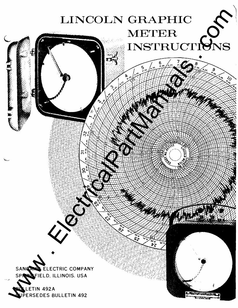
LINCOLN GRAPHIC
SANGAMO ELECTRIC COMPANY
SPRINGFIELD, ILLINOIS, USA
BULLETIN 492A
SUPERSEDES BULLETIN 492
MErrER
INSTRUCTIONS
\
1 .j
\� www .
Elec
tricalP
artM
anua
ls . c
om
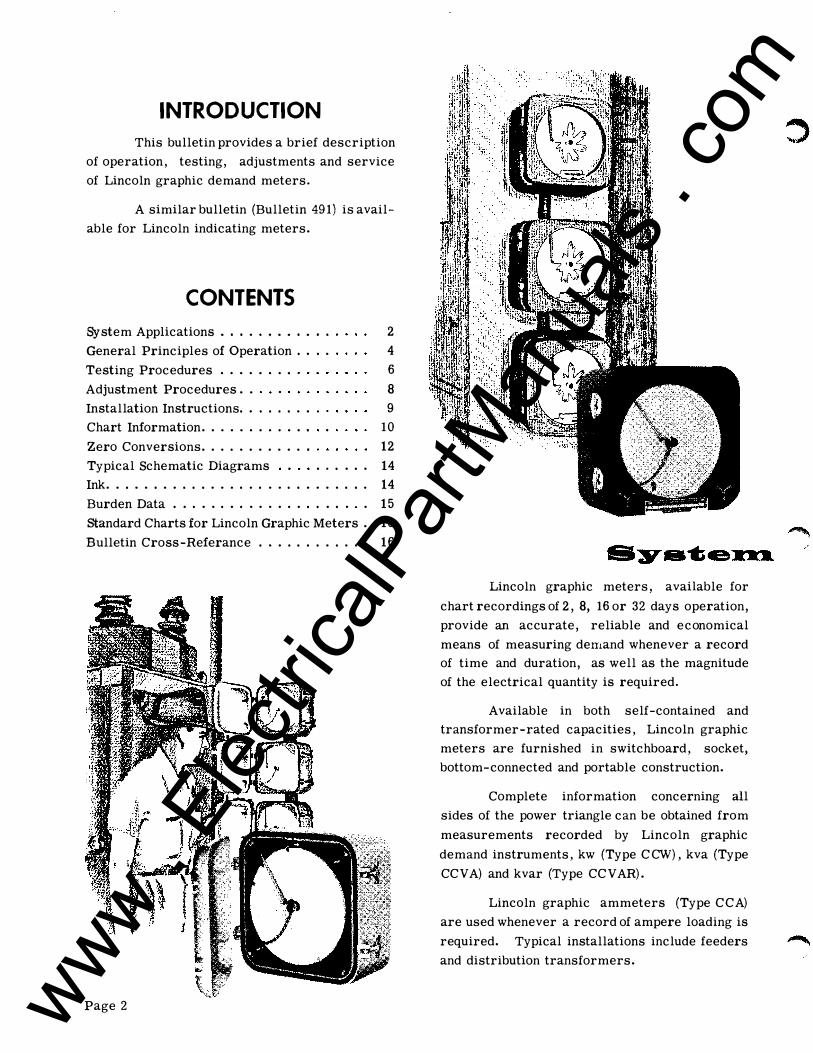
INTRODUCTION
This bulletin provides a brief description
of operation, testing, adjustments and service
of Lincoln graphic demand meters.
A similar bulletin (Bulletin 491) is avail
able for Lincoln indicating meters.
CONTENTS
System Applications . . . . . • . . . . • .
General Principles of Operation .. ..
Testing Procedures . . . . . . . .
Adjustment Procedures . .
Installation Instructions .. ..... .
Chart Information . . . . . . . . . . . .
Zero Conversions . . . .. . . . . . . .
2
4
6
8
9 10
12
Typical Schematic Diagrams . . . . .. 14
Ink. . . . . . . . . . . . . . . . . . . . . . . . . . .. 14
Burden Data . . . . . . . . . . . . . . . . . . . .. 15
standard Charts for Lincoln Graphic Meters . 16
Bulletin Cross-Referance . . . . . . . . . . . . 16
Page 2
Lincoln graphic meters, available for
chart recordings of 2, 8, 16 or 32 days operation,
provide an accurate, reliable and economical
means of measuring demand whenever a record
of time and duration, as well as the magnitude
of the electrical quantity is required.
Available in both self-contained and
transformer-rated capacities, Lincoln graphic
meters are furnished in switchboard, socket,
bottom-connected and portable construction.
Complete information concerning all
sides of the power triangle can be obtained from
measurements recorded by Lincoln graphic
demand instruments, kw (Type CCW), kva (Type
CCV A) and kvar (Type CCV AR).
Lincoln graphic ammeters (Type CCA)
are used whenever a record of ampere loading is
required. Typical installations include feeders
and distribution transformers.
www . El
ectric
alPar
tMan
uals
. com

Lincoln graphic voltmeters (Type CCV)
record "steady state" voltage conditions. The
thermal principle of operation serves to average
any surge or instantaneous peak voltage con
ditions. The resulting integrated record best
serves the utility engineer.
The chart timing mechanism, offered as
synchronous motor-drive, synchronous motor
drive with self-wound clock-driven carryover,
or hand-wound clock-drive, drives the chart to
show the time at which the demand occurs and is
entirely independent of the measuring element.
Lincoln graphic "circular charts" (giving
the Lincoln graphic meter its "cc" designation)
are permanent, legible records of system con
ditions. They offer a simple, inexpensive means
of storing valuable system information. It is
possible to obtain an entire month of valuable
information on a single 8 inch chart.
""- .
Page 3 www . El
ectric
alPar
tMan
uals
. com
The principle on which the thermal meter
operates is the conversion of electrical energy
into heat. The heat developed in an electrical
circuit of given resistance is proportional to the
square of the current.
ELECTRICAL
INPUT
FIGURE 1 ..
HEAT
fllfff
By fusing together two metal strips with
different temperature coefficients of expansion,
a bimetal is formed. These metals will expand
at different rates when heat is applied, and since
they are attached to one another, the strip
will bend.
BIMETAL STRIP
ELECTRICAL
INPUT
FIGURE Z,.
When a bimetal is wound into a coil with
the outer end fixed, the inner end can be fastened
to a shaft which will rotate with the heating of
the bimetal. A pointer, or pen in the case of a
graphic instrument, can be fitted to the end of
the shaft to produce a deflection.
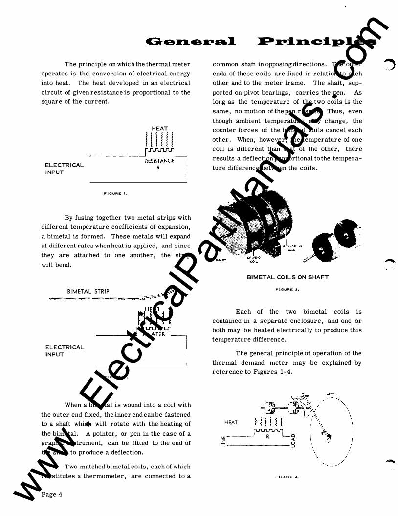
Two matched bimetal coils, each of which
constitutes a thermometer, are connected to a
Page 4
�:..-:l.lI1l. .0:1. P I e_
common shaft in opposing directions. The outer
ends of these coils are fixed in relation to each
other and to the meter frame. The shaft, sup
ported on pivot bearings, carries the pen. As
long as the temperature of the two coils is the
same, no motion of the pen results. Thus, even
though ambient temperature may change, the
counter forces of the bimetal coils cancel each
other. When, however, the temperature of one
coil is different than that of the other, there
results a deflection proportional to the tempera
ture difference between the coils.
BIMETAL COILS ON SHAFT
FIGURE: 3.
Each of the two bimetal coils is
contained in a separate enclosure, and one or
both may be heated electrically to produce this
temperature difference.
The general principle of operation of the
thermal demand meter may be explained by
reference to Figures 1-4.
HEAT
�----��� �. ·9
FIGURe; 4.
www . El
ectric
alPar
tMan
uals
. com

c When current is passed through a Lincoln
ammeter, for example, heat proportional to
I2R is developed in one enclosure which raises
the temperature above that of the other enclo
sure. The bimetal coils, responding to this
difference in temperature, produce a deflection
proportional to the electrical quantity being
measured. Since Lincoln meters have an in
herent thermally lagged response, a certain
length of time is required for the heater to raise
the temperature of its enclosure and the bimetal
coil to the ultimate temperature. Thus, the
pen approaches the ultimate indication slowly.
In all Lincoln instruments, deflection is
caused by a temperature difference between two
bimetal coils. For the circuitry of the other
typical Lincoln meters, consult the wiring dia
grams contained on page 14 of this bulletin.
The "Time Interval", as it is customarily
defined, is the amount of time required to record
90% of the CHANGE in load.
Figure 5 shows a typical response curve
of the Lincoln thermal meter for a steady load
110
100
90
80
Cl
i!: 70 0 0{ 60 LOAD 0 ..J
3: 50 � ' ... ----INDICATION
40
30
20
10
condition. It can be seen from this curve that
approximately 90% of the change in load is
recorded on the meter in the first time interval.
In the following interval, it res ponds to 90% of the
difference between the reading at the beginning
of the interval and the load level or 99% of the
change. In the third interval, the meter reads
99.9% of the change. This averaging continues
until there is another change in the load.
The time interval is set in a Lincoln
meter by the thermal design of the enclosure in
which the bimetal is placed. Unless otherwise
marked on the nameplate, the time interval of
a Lincoln demand meter, with the exception of
all Lincoln voltmeters, is 15 minutes. Volt
meters have a time interval of apprOximately
10 minutes.
STANDARD LINCOLN TIME INTERVALS
Amperes (CCA) 15 Minutes.
Volts (CCV) 10 Minutes.
Power: KW (CCW), KVA (CCVA) and
KVAR (CCVAR) 15 Minutes.
100%-110KW
'--- 99 %- 109 KW
0 2
TIME INTERVALS
3 4
FIGURE 5. 'TYPICAL THERMAL RESPONSE CURVE (STEADY LOAD).
Page 5 www . El
ectric
alPar
tMan
uals
. com
GENERAL
One of the important characteristics of
the Lincoln demand meter is its inherent time
lag. Three intervals are required for the meter
to record 99.9% of test load.
The testing time of three intervals indi
cates that the most economical method of testing
Lincoln meters is to test a group in series. The
larger the group, the lower will be the cost per
meter. Therefore, it is recommended that
thermal meters be gang tested in the meter shop
instead of individually tested in service.
Before the actual testing and adjustment
procedures, the meters to be tested should be
warmed on potential for at least 3 hours, or in
the case of Lincoln ammeters left at room tem
perature for at least 3 hours. This precaution
insures that any variations in ambient tempera
ture conditions between the meter coils are
adequately compensated for prior to testing
and adjustments.
Polyphase Lincoln Types CCVAR, CCVA,
and the special CCW/CCVAR meters can be
tested as kw demand meters with a single phase
load applied and the switch on the 100% pf po
sition. Single phase CCVAR meters must be
tested with a var load applied unless the meter
is one of the newer types with a toggle switch
for kw measurement.
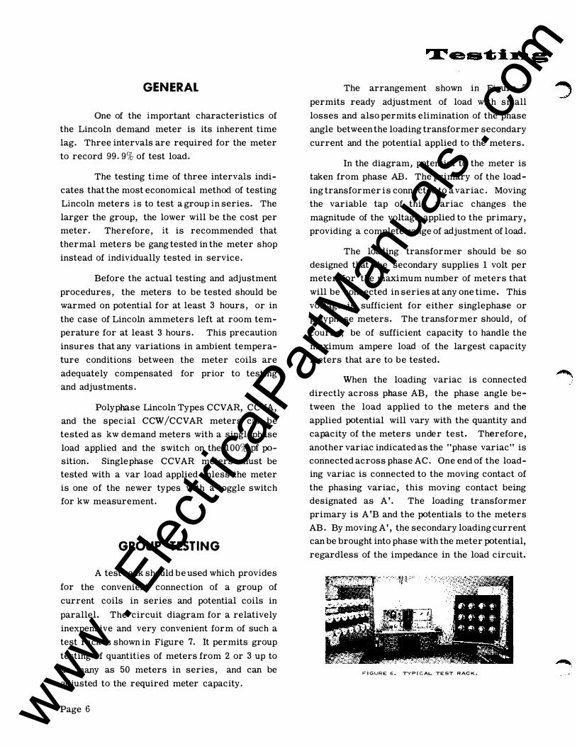
GROUP TESTING
A test rack should be used which provides
for the convenient connection of a group of
current coils in series and potential coils in
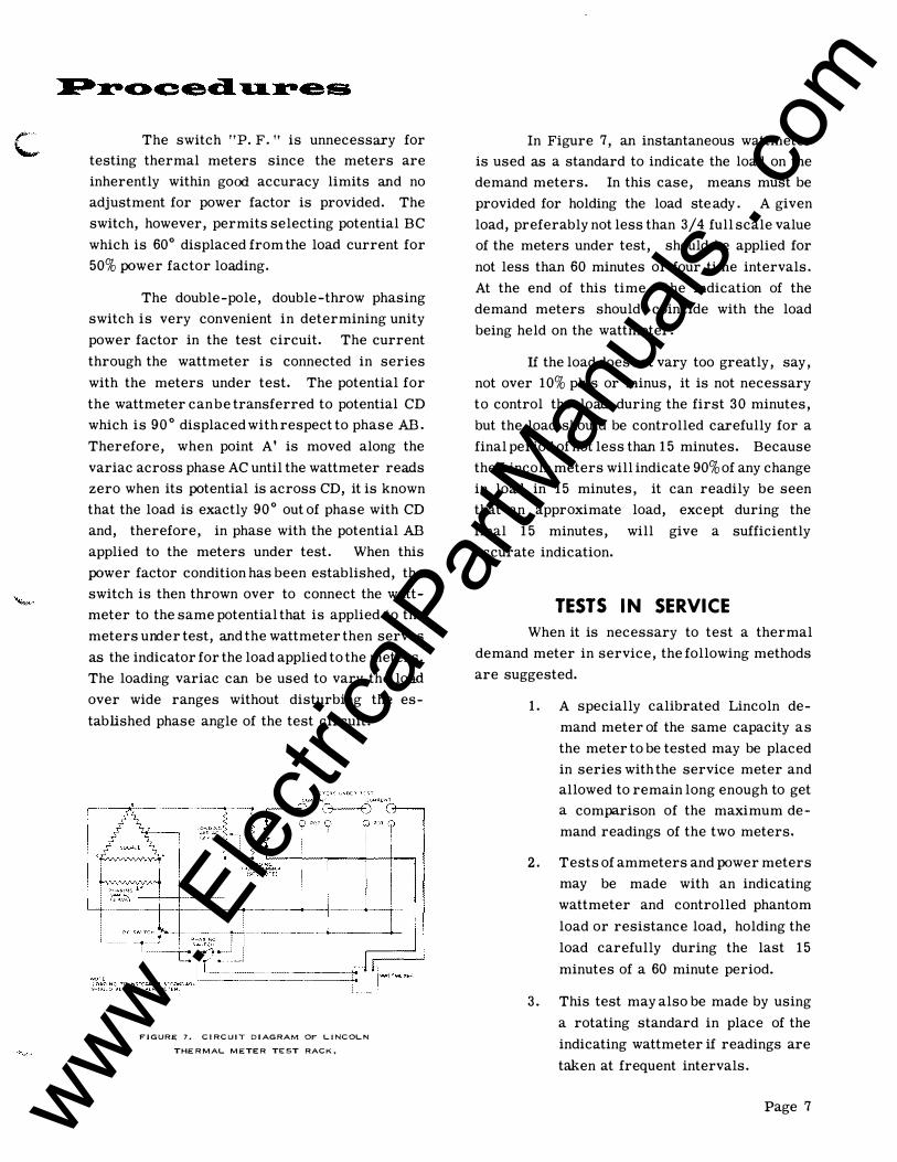
parallel. The circuit diagram for a relatively
inexpensive and very convenient form of such a
test rack is shown in Figure 7. It permits group
testing of quantities of meters from 2 or 3 up to
as many as 50 meters in series, and can be
adjusted to the required meter capacity.
Page 6
The arrangement shown in Figure 7
permits ready adjustment of load with small
losses and also permits elimination of the phase
angle between the loading transformer secondary
current and the potential applied to the meters.
In the diagram, potential to the meter is
taken from phase AB. The primary of the load
ing transformer is connected to a variac. Moving
the variable tap of this variac changes the
magnitude of the voltage applied to the primary,
providing a complete range of adjustment of load.
The loading transformer should be so
designed that the secondary supplies 1 volt per
meter for the maximum number of meters that
will be connected in series at any one time. This
voltage is sufficient for either singlephase or
polyphase meters. The transformer should, of
course, be of sufficient capacity to handle the
maximum ampere load of the largest capacity
meters that are to be tested.
When the loading variac is connected
directly across phase AB, the phase angle be
tween the load applied to the meters and the
applied potential will vary with the quantity and
capacity of the meters under test. Therefore,
another variac indicated as the "phase variac" is
connected across phase AC. One end of the load
ing variac is connected to the moving contact of
the phasing variac, this moving contact being
designated as A'. The loading transformer
primary is A 'B and the potentials to the meters
AB. By moving A', the secondary loading current
can be brought into phase with the meter potential,
regardless of the impedance in the load circuit.
FIGURE: 6 .. TYPICAL TEST RACK.
www . El
ectric
alPar
tMan
uals
. com
c The switch Itp. F. It is unnecessary for
testing thermal meters since the meters are
inherently within good accuracy limits and no
adjustment for power factor is provided. The
switch, however, permits selecting potential BC
which is 60° displaced from the load current for
50% power factor loading.
The double-pole, double-throw phasing
switch is very convenient in determining unity
power factor in the test circuit. The current
through the wattmeter is connected in series
with the meters under test. The potential for
the wattmeter can be transferred to potential CD
which is 90° displaced with respect to phase AB.
Therefore, when point A' is moved along the
variac across phase AC until the wattmeter reads
zero when its potential is across CD, it is known
that the load is exactly 90° out of phase with CD
and, therefore, in phase with the potential AB
applied to the meters under test. When this
power factor condition has been established, the
switch is then thrown over to connect the watt
meter to the same potential that is applied to the
meters under test, and the wattmeter then serves
as the indicator for the load applied to the meters.
The loading variac can be used to vary the load
over wide ranges without disturbing the es
tablished phase angle of the test circuit.
FJGURE 7. CIRCuiT DIAGRAM OF LINCOLN
THERMAL METER TEST RACK.
In Figure 7, an instantaneous wattmeter
is used as a standard to indicate the load on the
demand meters. In this case, means must be
provided for holding the load ste ady . A given
load, preferably not less than 3/4 full scale value
of the meters under test, should be applied for
not less than 60 minutes or four time intervals.
At the end of this time, the indication of the
demand meters should coincide with the load
being held on the wattmeter.
If the load does not vary too greatly, say,
not over 10% plus or minus, it is not necessary
to control the load during the first 30 minutes,
but the load should be controlled carefully for a
final period of not less than 15 minutes. Because
the Lincoln meters will indicate 90% of any change
in load in 15 minutes, it can readily be seen
that an apprOximate load, except during the
final 15 minutes, will give a sufficiently
accurate indication.
TESTS IN SERVICE
When it is necessary to test a thermal
demand meter in service, the following methods
are suggested.
1. A specially calibrated Lincoln de
mand meter of the same capacity as
the meter to be tested may be placed
in series with the service meter and
allowed to remain long enough to get
a comparison of the maximum de
mand readings of the two meters.
2. Tests of ammeters and power meters
may be made with an indicating
wattmeter and controlled phantom
load or resistance load, holding the
load carefully during the last 15
minutes of a 60 minute period.
3. This test may also be made by using
a rotating standard in place of the
indicating wattmeter if readings are
taken at frequent intervals.
Page 7 www . El
ectric
alPar
tMan
uals
. com

GENERAL
Two adjustments are provided on all
Lincoln meters: the zero adjustment procedure
and the deflection (or full load) adjustment. The
zero adjustment procedure differs on Lincoln
voltmeters as a result of the suppressed zero
scale peculiar to these meters. Consequently,
adjustments for voltmeters will be explained
separately. The inherent power factor charac
teristics of the Lincoln design are such that no
adjustment is required. The location and
operation of adjustments are the same for all
Lincoln graphic meters (Figures 8 and 9).
Load checks need be made at only one
JXlint. The check should be made above 3/4 scale
since calibration at zero and 3/4 scale or higher
is necessary to insure accuracy at all inter
mediate points. Adjustments at points lower
than 3/4 scale may introduce excessive errors
at full scale, since the full load adjustment spring
has an effect proportional to the scale point (that
is, no effect at zero and maximum effect at
full scale).
No adjustment has been provided for
balance between the elements in three-wire and
four-wire meters. All meters are carefully
checked for balance at the factory, and the design
is such that the balance is not subject to change.
FIGURE 8.
Page 8
DEFLE:CTlOh OR
FULl... LOAD
ADJUSTMENT
FIGURE 9,
ZERO CHECK & ADJUSTMENT
Zero should be checked only when the
meters have been in the test room and warmed
on uninterrupted JXltential, with the current
circuit open, for at least 3 hours. Under this
condition, the reading of the pen should be zero;
that is, on the zero line. If any adjustment is
needed, the finger operated wheel, as shown in
Figure 8, is rotated.
DEFLECTION ADJUSTMENT
Before making the deflection or full load
adjustment, a minimum of 3/4 scale load should
be applied for at least 4 time intervals. The
deflection adjustment or full load adjustment
consists of a drum and chain connected to a
helical spring. The spring exerts a retarding
force on the pen assembly. By turning the slotted
drum head with a screw driver, the spring torque
pull on the pen assembly can either be increased
or decreased. If the reading of the meter is low,
decrease the tension on the spring, and if the
reading is high, increase the tension.
www . El
ectric
alPar
tMan
uals
. com

VOLTMETER ADJUSTMENT
All Lincoln voltmeters have a suppressed
zero. To calibrate the meters, two adjustments
are required: on-seale-zero and the deflection
or full scale adjustment. The on-seale-zero of
the suppressed zero scale is the voltage at which
the deflection spring has no torque.
The zero adjustment is made with on
scale-zero voltage applied to the meter. For
Lincoln graphic meters, zero adjustment is made
at 95 volts and 190 volts for 120 and 240 volt
meters respectively. Since the true zero is
suppressed, it will require about 30 minutes,
or three time intervals, for the meter to indicate
the on-zero reading. After the on-seale-zero
test, apply full scale voltage for at least 35
Lincoln thermal demand meters are
shipped completely assembled, adjusted and
tested, ready for service. Meters should be
installed in a place easily accessible for reading
and where there is not excessive vibration.
Graphic type thermal meters are larger
than service type watt hour meters and require
more space for mounting. Terminal chambers,
however, are such that standard watthour meter
trims, boxes or test blocks can be used with
Lincoln graphic meters.
Lincoln ammeters are connected in
service by connecting their current coils in
series with current coils of other instruments
in the circuit.
Lincoln voltmeters are connected in
service by connecting their potential coils in
parallel with the potential coils of other instru
ments in the circuit.
minutes. If necessary, adjust meter reading to
full scale by means of full scale adjustment.
After the deflection adjustment, repeat
the zero adjustment test and readjust if
necessary. If readjustment of zero is required,
then full scale must be rechecked.
FIGURE 10.
Lincoln kw, kva and kvar demand meters
are installed with their current coils in series
with the corresponding current coils of other
instruments and their corresponding potential
coils in parallel. Proper phase sequence on
wiring diagram must be observed on polyphase
kva and kvar meters.
In all cases, except when 5 ampere
watthour meters are involved, the Lincoln power
demand meters may be connected either on the
line or the load side of the watthour meter, as
the watts loss in the potential coils of any Lincoln
demand meter is less than the watts required to
start a watthour meter of over 5 ampere capacity.
All 5 ampere Lincoln power demand meters are
for use with transformers and are equipped with
separate potential terminals. Because the
potentials of these meters can be carried to a
point ahead of the watthour meter, the demand
meter can be mounted on the load side of the
watthour meter. All meters can be supplied
with independent potentials, if so specified.
Page 9 www . El
ectric
alPar
tMan
uals
. com

CHART DRIVES
Lincoln graphic meters are available with
three different types of chart drives.
1. Synchronous motor-drive.
2. Synchronous motor-drive with clock
carryover.
3. Hand wound clock-drive, 15 day
clock movement.
The last two types of drives entail clock
movements and should be sent to the factory or
taken to a watchmaker for repair or adjustment.
FIGURE 11,
SYNCHRONOUS CARRYOVER
With the synchronous carryover feature,
the chart is normally driven by a synchronous
motor. In the case of a power outage, however,
the drive is automatically transferred to a spring
movement. A fully wound mainspring in the clock
is capable of driving the train for 14 hours.
When power is restored, the drive automatically
transfers to the synchronous motor. These
transfers are accomplished by means of a bi
metallic blocking device which is heated when
the synchronous motor is energized. This blocks
the movement of the escapement in the clock.
Conversely, when the device cools due to the loss
of voltage, it quickly releases the escapement
and allows the clock to function.
Upon power resumption, the synchronous
motor rewinds the mainspring, requiring about
54 hours for a completely unwound mainspring.
Page 10
In order to prevent the spring movement
from running during storage and shipment, a
manually operated lock is provided to block the
operation of the escapement. This lock is oper
ated by means of a slotted shaft, "A" ( Figure 11)
located at the position marked" LOCK" On the
front of the train. The meter is shipped from the
factory with the lock in the "ON" position. When
the meter is installed and energized, the lock
must be turned to the "OFF" position so that the
thermal blocking device will be free to operate.
SYNCHRONOUS MOTOR
The porous type bronze sleeve bearings
of this motor are vacuum-impregnated with a
special silicon compound which provides
adequate lubrication over wide ranges of temper
ature and climatic conditions.
Field lubrication is considered unneces
sary, even after years of operation. If inspection
is desired, the most effective means is to supply
reduced voltage to the motor and test for
synchronous speed. If the motor synchronizes
under load at 75% rated voltage, no further check
is needed. The Type H motor operates at a
synchronous speed of 450 rpm. Markings are
provided on the motor for a stroboscope check
of synchronous operation.
CHART SPEED CHANGES
Lincoln graphic meters may be equipped
for chart speeds of 2, 8, 16, or 32 days. As
indicated by Figure 11, conversion from one
chart speed to another is accomplished by
changing the chart drive speed changing attach
ment. By simply removing three screws, the
existing gear assembly can be removed and the
appropriate gear assembly easily inserted in its
place. No other adjustments are required.
It is also possible to replace a synchro
nous drive mechanism with a synchronous
carryover type by disconnecting motor leads and
removing four mounting screws (Figure 11).
www . El
ectric
alPar
tMan
uals
. com

CHANGING CHARTS
The chart can be set to show correct
time more accurately if the pen is used as the
indicator rather than the time indicator on the
platen. Settings should be made toward the outer
edge of the chart where the chart is more easily
read. The time indicator, a chart tab on the
platen immediately below the full load adjust
ment hole, however, provides a quick and effect
ive method of aligning the chart. When using
this method, align the heavy time line with the
arrow on the time indicator.
In setting the time of the chart, it is
important that the backlash of the gears be taken
up completely. This is accomplished by turning
the chart holder nut clockwise. This precaution
assures more accurate time setting. In setting
the chart, the following steps are required:
1. Place chart on meter and replace
chart holder nut.
2. Check time setting of chart by use
of pen or time indicator. Adjust
until pen indicates correct time.
3. Take up backlash as described above.
4. Swing pen from inside to outside of
chart. If necessary, readjust for
backlash and again check time
setting.
CHART CONSTANTS
The chart constant (K) is a multiplier
applied to the actual chart reading in order to
convert it to the primary load measured by the
meter. The chart constant may be something
other than K 1 for several different reasons.
An easily read chart, such as 1 kw, may be
specified for all capacities, or a direct reading
chart may not be available for certain special
capacities. Where instrument transformers are
used, the actual chart reading must also be
multiplied by potential and current transformer
ratios. The chart K is determined as the ratio
of full scale meter capacity to full scale of
the chart or
Chart K Full Scale of Meter
Full Scale of Chart
Example: If a 6 ampere full scale chart is used
on a meter rated at 3 amperes,
Chart K 3/6 = 1/2;
therefore, all chart readings must be multiplied
by 1/2 in order to obtain the correct current
value measured by the meter. If 200:5 current
transformers are being used, for example, the
chart reading would also have to be multiplied
by the CTR � 40. Thus, a chart reading
of 2.5 amperes would be multiplied to primary
amperes by
Primary Amperes = Chart Amperes x K x CTR
Primary Amperes = 2.5 x 1/2 x 40 '" 50 Amps.
CHART SUGGESTIONS
1. Store charts in air-conditioned, dry
places, not at outside locations.
2. Do not over-fill the pen nib. One
drop lasts 32 days.
3. Replace a dirty pen nib with a clean
one. Dirty nibs can be cleaned or
repiaced at a very low cost.
4. To insure positive pen contact with
the graphic chart, the meter should
be vertical or tilted slightly back
wards (10 _ 3°).
Page 11 www . El
ectric
alPar
tMan
uals
. com
Sometimes it is necessary to convert the
zero position of a graphic meter. In the case of
inside to outside zero or vice versa, time reso
lution is usually the deciding factor. Time is
much easi er to read in the outer half of the chart.
Conversion to or from raised zero is generally
dependent on the possibility of reversed power
flow or leading power factor conditions.
In any case, the zero position of the pen
on most Lincoln graphic meters can be con
verted from the original position to any of three
other positions. Chart zero positions are in
side, outside, center or 1/3 raised zero. The
following procedures outline the necessary steps.
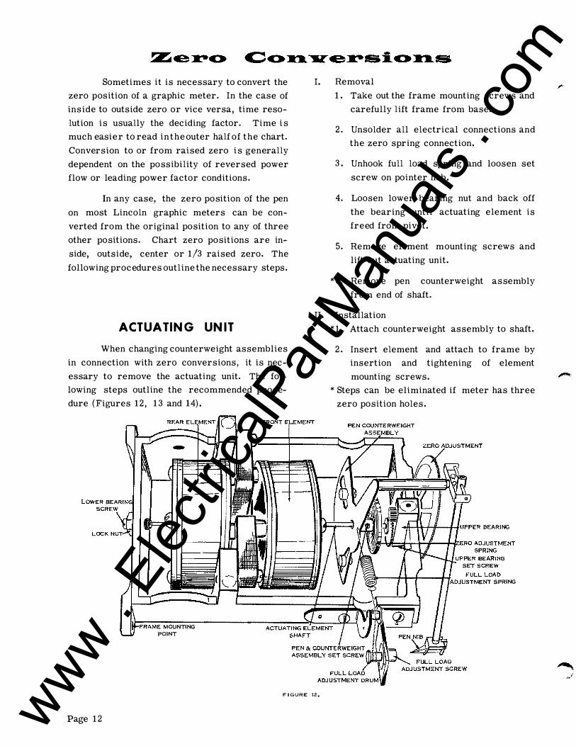
ACTUATIN G UN IT
When changing counterweight assemblies
in connection with zero conversions, it is nec
essary to remove the actuating unit. The fol
lowing steps outline the recommended proce
dure (Figures 12, 13 and 14).
MOUNTING POINT
I. Removal
1. Take out the frame mounting screws and
carefully lift frame from base.
2. Unsolder all electrical connections and
the zero spring connection.
3. Unhook full load spring and loosen set
screw on pointer hub.
4. Loosen lower bearing nut and back off
the bearing until actuating element is
freed from pivot.
5. Remove element mounting screws and
lift out actuating unit.
*6. Remove pen counterweight assembly
from end of shaft.
II. Installation
*1. Attach counterweight assembly to shaft.
2. Insert element and attach to frame by
insertion and tightening of element
mounting screws.
* Steps can be eliminated if meter has three
zero position holes.
1I1<:'TU""''T SPRING
FIGURE 12.
Page 12 www . El
ectric
alPar
tMan
uals
. com
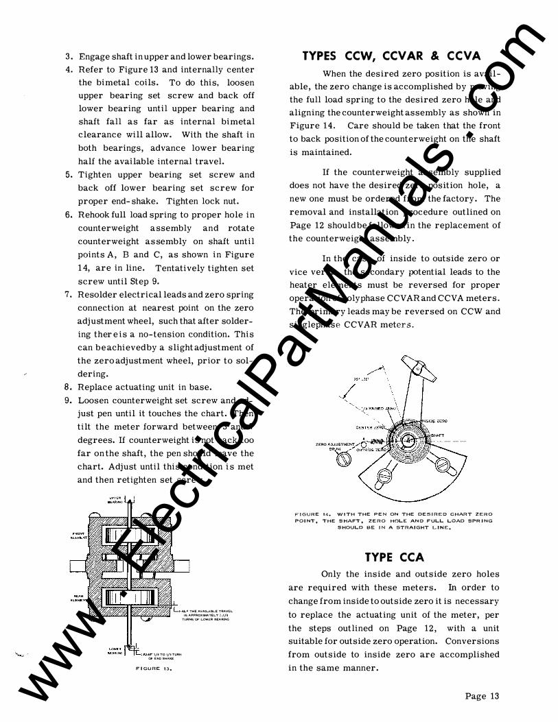
3. Engage shaft in upper and lower bearings.
4. Refer to Figure 13 and internally center
the bimetal coils. To do this, loosen
upper bearing set screw and back off
lower bearing until upper bearing and
shaft fall as far as internal bimetal
clearance will allow. With the shaft in
both bearings, advance lower bearing
half the available internal travel.
5. Tighten upper bearing set screw and
back off lower bearing set screw for
proper end-shake. Tighten lock nut.
6. Rehook full load spring to proper hole in
counterweight assembly and rotate
counterweight assembly on shaft until
pOints A, Band C, as shown in Figure
14, are in line. Tentatively tighten set
screw until Step 9.
7. Resolder electrical leads and zero spring
connection at nearest point on the zero
adjustment wheel, such that after solder
ing ther e is a no-tension condition. This
can be achieved by a slight adjustment of
the zero adjustment wheel, prior to sol
dering.
8. Replace actuating unit in base.
9. Loosen counterweight set screw and ad
just pen until it touches the chart. Then
tilt the meter forward between 3 and 7
degrees. If counterweight is not back too
far on the shaft, the pen should leave the
chart. Adjust until this condition is met
and then retighten set screw.
1/4 TO l/3TURN OF END SHAKE
FIGURE 13.
THE AvAIL,AElLE TRAVEL IS APP�O)(IMATEL Y 2_1/4
TURNS OF LOWER BEARING
TYPES CCW, CCV AR & CCV A
When the desired zero position is avail
able, the zero change is accomplished by moving
the full load spring to the desired zero hole and
aligning the counterweight assembly as shown in
Figure 14. Care should be taken that the front
to back position of the counterweight on the shaft
is maintained.
If the counterweight assembly supplied
does not have the desired zero position hole, a
new one must be ordered from the factory. The
removal and installation procedure outlined on
Page 12 should be followed in the replacement of
the counterweight assembly.
In the case of inside to outside zero or
vice versa, the secondary potential leads to the
heater elements must be reversed for proper
operation of polyphase CCVAR and CCVA meters.
The primary leads may be reversed on CCW and
singlephase CCVAR meters.
ZERO AOJU" MtN< .... ' J
FIGURE 14. WITH THE PEN ON THE DESIREO CHART ZERO
POINT. THE SHAFT. ZERO HOLE ANO FULL l..OAD SPRING
SHOULD BE IN A STRAIGHT LINE ..
TYPE CCA
Only the inside and outside zero holes
are required with these meters. In order to
change from inside to outside zero it is necessary
to replace the actuating unit of the meter, per
the steps outlined on Page 12, with a unit
suitable for outside zero operation. Conversions
from outside to inside zero are accomplished
in the same manner.
Page 13 www . El
ectric
alPar
tMan
uals
. com

TYPE CCV
Zero conversions on Lincoln graphic
voltmeters are not advised. Operation within
the chart voltage limits is obtained without the
need for zero conversions.
CAUTION:
Meters having an actuating unit which is
not physically symmetrical should not be used as
1/2 raised zero meters. Actuating units which
are not physically symmetrical will perform
differently on forward and reverse operation.
If a physical dissymmetry between the front and
rear elements is noticed, the factory should be
consulted regarding conversion to 1/2 raised
zero operation.
One drop of the special slow-drying ink
used in the graphic meter pen assures an adequate
supply for a 32 day record over a temperature
range from -20°F. to a maximum summer con
dition. For operation below -200, undiluted
methyl, ethyl, or propyl alcohol should be added
to the ink to insure proper flow. The mixture
should be in the following proportion: Ink=90%,
Alcohol=10%. Sangamo also supplies two types of
pen nibs; one for low temperature conditions and
one for normal and high temperature conditions.
SEC ON
"TOP
--l I I I I I I
TYPICAL
SCHEMATIC
DIAGRAMS·
TYPE CCAS
UNE.
TYPE CCWS
I I 1 : I r-t--f-,-....J I I I I
��
I
t J-/ / I---r-- � I ../
LOI>.D
rOil ..lSI: wrtl4 (II1II:51'1:"'''
e... il>d"tt ... "t, .... '.- TItA>.ISf'olt .... �tt"
TYPE CCVS
TYPE CCVARS
cO"'''
��'f. �n ... � .. t_". u __ _
*The very large number of internal and external connection diagrams associated with Lincoln graphic meters prohibits their
inclusion in this bulletin. The diagram supplied with the meter should be consulted for detailed wiring information.
Page 14 www . El
ectric
alPar
tMan
uals
. com

CURRENT CIRCUITS
Rated R X Z Volt-Amps. Watts P.F.
Type Phase Wire Elements Amps. Full Scale (ohms of highest phase) (at rated amperes)
CCA 1 2 1 3 3 amps .485 .077 .491 4.42 4.36 .99
CCA 1 2 1 5 5 amps .175 .028 .177 4.42 4.36 .99
CCA 1 2 1 6 6 amps .121 .019 .123 4.42 4.36 .99
With instantaneous ammeter, add. 25 VA at 1. 0 P. F.
(120 volt)
CCW 1 2 1 5 0.75 kw .103 .040 .110 2.76 2.58 .93
CCW 3 3 or 4.6. 2 5 1. 50 kw .076 .031 .082 2.05 1. 90 .93
CCW 3 4Y 2 5 2.25 kw .077 .055 .094 2.36 1. 92 .81
CCW 3 4Y 3 5 2.25 kw .072 .028 .077 1. 92 1. 79 .93
For other full scale capacities: R, X and Z vary inversely as the square of the capacities. As an example, a 1. 0 kw 14> CCW
would have R (.103)(.75)2
= .058 ohm. (1. 0)2
For computing burden, the capacity of a raised zero meter is the sum of the forward and backward capacity. CCVA and CCV AR
meters have same current circuit burden as corresponding CCW.
POTENTIAL CIRCUITS
Maximum V. A. Watts Power
Phase Wire Elements Element Element Factor
CCV 1 2 1 4.65 4.65 1. 00
CCVA 3 3 2 3.62 1.71 .47
CCVA 3 4Y 2 4.43 2.05 .46
CCVA 3 4Y 3 1. 40 1. 15 .83
CCVAR 1 2 1 4.10 2.79 .68 lead
CCVAR 3 3 2 3.76 3.76 1. 00
CCVAR 3 4Y 2 4.53 4.53 1. 00
CCVAR 3 4Y 3 1. 30 1. 10 .85
CCW 1 2 or 3 1 3.55 2.70 .76
CCW 3 3 or 4 2 2.62 1. 60 .61
CCW 3 4Y 3 1.11 1. 00 .90
Above burdens do not include chart motor. Motor adds 4.26 VA, 2.34 watts, .55 P. F. to one phase.
Page 15 www . El
ectric
alPar
tMan
uals
. com
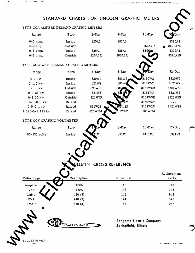
STANDARD CHARTS FOR LINCOLN GRAPHIC METERS
TYPE CCA AMPERE DEMAND GRAPHIC METERS
Range Zero 2-Day 8-Day 16-Day
0-5 amp. Inside 825A2 885A2
0-5 amp. Outside 8165A2R
0-6 amp. Inside 826A1 886A1 8166A1
0-6 amp. Outside 826A1R 886A1R
TYPE CCW WATT DEMAND GRAPHIC METERS
Range Zero 2-Day 8-Day 16-Day
0-1 kw Inside 820W2 880W2 8160W2
0-1. 5 kw Inside 821W2 881W2 8161W2
0-1. 5 kw Outside 821W2R 881W2R 8161W2R
0-2.25 kw Inside 821W3 881W3 8161W3
0-2.25 kw Outside 821W3R 881W3R 8161W3R
0.5-0-0.5 kw Raised 880W2M 8160W2M
0.5-0-1 kw Raised 821W2S 881W2S 8161W2S
1. 125-0-1. 125 kw Raised 821W3M 881W3M 8161W3M
TYPE CCV GRAPHIC VOLTMETER
Range Zero 2-Day 8-Day 16-Day
95-135 volts Inside 821V1 881V1 8161Vl
BUllETIN CROSS-REFERENCE
Meter Type
Ampere
Volt
Watts
KVA
KVAR
BULLETIN 492A
Description
460A
470A
440 (3)
440 (3)
440 (3)
POWER EQUIPMENT
Price List
146
146
144
144
144
Sangamo Electric Company
Springfield, Illinois
32-Day
8325A2
8325A2R
8326A1
8326A1R
32-Day
8320W2
8321W2
8321W2R
8321W3
8321W3R
8321W2S
32-Day
8321V1
Replacement
Parts
943
943
943
943
943
0565 PRINTED IN U.S.A.
;r
,.-. I \ ,
www . El
ectric
alPar
tMan
uals
. com


![Sangamo Journal, [newspaper]. December 12, 1835](https://img.pdfslide.us/doc/110x75/628a701e1f90ee690914bdfd/sangamo-journal-newspaper-december-12-1835.jpg)