Embed Size (px)
Citation preview
DECS-200 Digital Excitation Control System
One DECS-200 Digital Excitation Control System can accommodate 32Vdc, 63Vdc, or 125Vdc applications up to 15Adc. This unique flexibility provides precision control of generators of virtually any size. The DECS-200 also incorporates a pulse width modulated power stage, which improves system performances in non-linear load applications.
FEATURES • Microprocessor-based design • True RMS sensing, single or three phase • 32Vdc, 63Vdc, and 125Vdc outputs at 15Adc • 0.25% Voltage Regulation Accuracy • Setup from front panel HMI or by PC with Windows® setup software included • 20 standard stability selections • User customizable stability selection • Paralleling compensation • Underfrequency compensation or V/Hz Ratio Limiter • Soft start buildup • Field Current Regulation Mode (Manual Mode) • Autotracking between operating modes and between DECS-200 units
(optional) • Autotransfer to a back-up DECS-200 unit (optional) • Minimum Excitation Limiter (Internally generated or customizable) • On and off-line Maximum Excitation Limiters • Var and Power Factor Controllers • Exciter Diode Monitoring (EDM) • Sequence of Events Recording • Oscillography (continued on next page)
WINDOWS® SOFTWARE Interface for setting and communicating with Basler products
Request BESTCOMS TM -DECS200-32 (Windows® NT 3.51 or later, 95, 98, or Me)
ADDITIONAL INFORMATION INSTRUCTION MANUAL
Request Publication 9360100990
§.Basler Electric P. 0. BOX 269 HIGHLAND, ILLINOIS, U.S.A. 62249 PHONE 618·654·2341 FAX 618·654·2351
DESCRIPTION and SPECIFICATIONS Pages 2 through 5
FEATURES and FUNCTIONS
Pages 6 and 7
INTERCONNECT DIAGRAM
PageS
FRONT, SIDE VIEWS and DIMENSIONS Pages 9 through 11
ORDERING Page 12
SZM-3
1-02 www . El
ectric
alPar
tMan
uals
. com
DECS-200 Digitai.Excitation Control System ��ft:' \";':'<>-';:>h_'f'<i;�}P/'J:r:dz.-'-,)>·3-<,
FEATURES, continued • Voltage Matching • Seven (7) generator protection features • Programmable output contacts • Front panel backlit LCD display • Front panel mounted RS-232 and side RS-485
communications ports • Mod bus TM protocol for RS-485 input allows
communications up to 4000 feet away • < 1 % metering accuracy for 12 generator parameters
• Remote set point control via: - Contact inputs - Proportional control via ± 1 OVdc or 4-20mA
- Communications inputs RS-232 (ASCII) or RS-485 (ModbusTM)
• Meets C37 .90.1-1989 for Surge Withstand and Fast Transient
• UL recognized, CSA certified, CE compliant • U.S. Patent Number 5, 294, 879
DESCRIPTION The microprocessor based DECS-200 is a total excitation control system in one enclosure. It contains all the functionality necessary to limit, control, and protect a generator from operating outside of the machine's capability. An optional feature of DECS-200's sophisticated design allows the nonactive control mode within the unit to follow the active mode, permitting bumpless transfer between modes. The optional software also allows for unit-to-unit communication,
permitting autofollowing and transfer between DECS-200 units. It can also communicate to a PC via the front panel RS-232 port for local programming and metering, and it can communicate via Modbus™ protocol via the side RS-485 port for communications up to 4000 feet away from the DECS-200 unit. The DECS-200 has all the features, functionality, flexibility and programmability expected from a state-of-the-art microprocessor based product.
APPLICATIONS The DECS-200 is an excitation control system used to control the output voltage, vars or power factor of a synchronous generator by varying or controlling the amount of de excitation applied to the generator's exciter field. The DECS-200 is suitable for virtually any size machine.
SPECIFICATIONS INPUTS
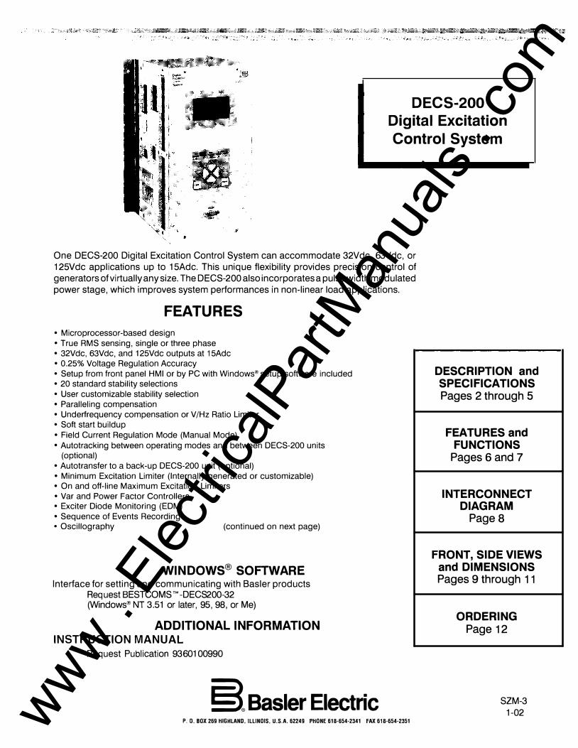
Control Power (style selectable) 16-60Vdc, Burden=30W. 85-132Vac, 50 or 60Hz, Burden=50VA. 90-1 50Vdc, Burden=30W.
AC Operating Power 1 or 3 Phase Power Input
DECS-200 Output AC Voltage Nominal Range (50-400Hz) Burden 32Vdc 60Vac 56-70Vac ± 10% 780VA 63Vdc 1 20Vac 1 00-139Vac ± 10% 1570VA
1 25Vdc 240Vac 190-277Vac ± 1 0% 3070VA NOTE: To ach1eve the proper DECS-200 output voltage, the associated Operat1ng Power must be prov1ded.
Generator Voltage Sensing Single-phase or three-phase line voltage, four ranges: • 1 OOV/50Hz nominal (85 to 1 27V), 120V/60Hz nominal (94 to 153V) • 200V/50Hz nominal (170 to 254V), 240V/60Hz nominal (187 to 305V) • 400V/50Hz nominal (340 to 508V), 400V/60Hz nominal (374 to 600V) • 500V/50Hz nominal (425 to 625V), 600V/60Hz nominal (51 0 to 660V)
Bus Voltage Sensing Single-phase line voltage (AC), four ranges: • 100V/50Hz nominal (85 to 127V), 120V/60Hz nominal (94 to 153V) • 200V/50Hz nominal (170 to 254V), 240V/60Hz nominal (187 to 305V) • 400V/50Hz nominal (340 to 508V), 400V/60Hz nominal (374 to 600V) • 500V/50Hz nominal (425 to 625V), 600V/60Hz nominal (51 0 to 660V)
2 www . El
ectric
alPar
tMan
uals
. com
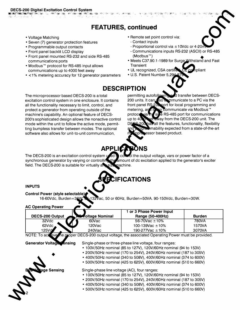
SPECIFICATIONS, continued Generator Current Sensing Two ac current sensing ranges and two channel (phase) inputs:
• 1A, phase B; 1A, phases A or C • 5A, phase B; 5A, phases A or C
Sensing Burden Voltage: Less than 1VA per phase. Current: Less than 1 VA. Parallel Compensation : Less than 1VA.
Contact Switching Inputs 11 contact switching inputs are supplied with 24Vdc to accommodate dry contacts. Contacts are as follows: • Start • Var/PF Enable • Stop • Pre-position • Secondary DECS Enabled (optional) • Raise Switch • Unit/Parallel Operation • Lower Switch • AVR Mode • Alarm Rest
• FCR Mode
Remote Set Point Control (Accessory Input)
Two separate analog inputs for remote set point control. Typically used to accept a signal from a Power System Stabilizer. Select one from the configuration menu. • ±10Vdc • 4 to 20 milliamperes
OUTPUTS
DC OUTPUT POWER: DECS is available in three standard models to meet the following field requirements.
DECS-200 DECS-200 DECS-200
Rated Continuous Field Voltage 32 Vdc 45 Vdc* 63 Vdc 90 Vdc* 125 Vdc
Rated Continuous Field Current 15 Adc 15 Adc 15 Adc 15 Adc 15 Adc
Rated 10 Second Forcing Voltage* 50 Vdc 75 Vdc* 100 Vdc 150 Vdc* 200 Vdc
Rated 10 Second Forcing Current 30 Adc 30 Adc 30 Adc 30 Adc 30 Adc
Minimum Field Resistance 2.13 Ohm 3.0 Ohm* 4.2 Ohm 6 . 0 Ohm* 8.3 Ohm
NOTE: Above parameters with nominal RMS power input. *These areas indicate D.C. output levels that may be up to 50% greater than listed if:
1) 3 phase input power is used, or 2) Field current is significantly lower than that listed.
Contact Output Ratings 7.0 Amps 120/240Vac, 24Vdc 0.7 Amps 48Vdc 0.2 Amps 125Vdc
Contacts are as follows: • Watchdog • Start/Stop • Relay #1 • Relay #2
180 Vdc*
15 Adc
300 Vdc*
30 Adc
12.0 Ohm*
• Relay #3
COMMUNICATION There are three communication ports, two RS-232 and one RS-485:
COMO: RS-232, 9 pin, sub-D connector located on front panel and used to
communicate with local computers. 1200 to 19200 baud, 8N1 full
duplex, ASCII commands COM1 : RS-232, 9 pin, sub-D connector located on right side panel and used to
connect primary and backup DECS-200 units or other devices. 1200 to
19200 baud, 8N1 full duplex, unique ASCII commands, only used for optional autotracking
3 www . El
ectric
alPar
tMan
uals
. com
Excitation Control System ------------·�----�' c2��;C�V�·�I*0�10c;7c"��£� ' �o<<c•·•C·•
REGULATION ACCURACY AVR Mode
FCR Mode
var Mode
PF Mode
Internal autotracking (optional)
PARALLEL COMPENSATION
FIELD OVERVOL TAGE PROTECTION
FIELD OVERCURRENT PROTECTION
EXCITER DIODE MONITOR (EDM)
GENERATOR UNDERVOLTAGE PROTECTION
SPECIFICATIONS, continued COM2: RS-485, located on left side panel and used to communicate with local
or remote computers or other devices. 1200 to 19200 baud, 8N1 half duplex, Mod bus TM protocol
Voltage regulation equals ± 0.25% over the load range at rated power factor and constant generator frequency. Steady state stability equals ± 0.1% at a constant load and generator frequency . Temperature drift equals ± 0.5% for 0 to 50°C temperature change. Underfrequency (volts/hertz) characteristic slope from 0 to 3.0 P.U. is adjustable in 0.1 P.U. increments.
Field current regulation equals ± 1.0% of the nominal value for 10% of the bridge input voltage change or 20% of the field resistance change.
± 2.0% of the nominal VA rating at the rated frequency.
± 0.02 PF in the set point PF for the real power between 10 and 100% at the rated frequency. (e.g. -set point PF=0.80, PF regulation is from 0.78 to 0.82 PF.)
± 0.5% of the nominal field voltage change when transferring.
Can use either reactive droop or reactive differential (cross-current) compensation. Adjustable from 0 to 30% of the rated generator voltage droop with optional 1 ampere or less or 5 amperes or less input. Line drop compensation uses this same parameter; however, it is adjustable from -30% to 0.
Adjustable in increments of 1.0Vdc from 1 .0 to 325Vdc rated output voltage with a 0.2 to 30 second inverse time delay settable in increments of 0.1 second.
Adjustable in increments of 0.1 Adc steps of rated field current from 0 to 16Adc excitation current setting with an inverse time delay (ANSI C50.13).
The DECS-200's EDM can detect open and shorted diodes on brush less generators. To do this, the DECS-200 requires the user to input the number of generator poles and the number of exciter poles (both adjustable from 0 to 20 in increments of 2). The open and shorted diode ripple threshold is adjustable from 0 to 100% of field current. The open diode protection time delay is adjustable from 10 to 60 seconds, and the shorted diode protection time delay is adjustable from 5 to 30 seconds.
Adjustable in increments of 1 Vac from 0 to 30kV sensing voltage setting with a 0.5 to 60 second inverse time delay (ANSI C50.13) settable in increments of 0.1 sec.
GENERATOR OVERVOLTAGE Adjustable in increments of 1Vac from 0 to 30kV sensing voltage with a 0.1 to 60 PROTECTION second inverse time delay (ANSI C50.13) settable in increments of 0.1 second.
LOSS OF SENSING The loss of sensing setting for both balanced and unbalanced generator voltage is adjustable from 0 to 100% of nominal generator voltage. The protection delay
is adjustable from 0 to 30 seconds in 0.1 increments.
SOFT START Functional in AVR and FCR with an adjustable rate of 1 to 200 volts per second in AVR, and 1 to 33% of the manual set point per second.
OVEREXCITATION LIMITING Limiter response time is less than three cycles.
4 www . El
ectric
alPar
tMan
uals
. com
On-Line
Off-Line
UNDEREXCITATION LIMITING
SEQUENCE OF EVENT RECORDING (SER)
OSCILLOGRAPHY
MANUAL EXCITATION CONTROL
VOLTAGE MATCHING
REAL TIME CLOCK
SURGE WITHSTAND CAPABILITY (SWC)
FAST TRANSIENT
HIGH POT.
ENVIRONMENTAL Operating temperature Storage temperature
Salt Fog
Shock
Vibration
Size
Weight
AGENCY
SPECIFICATIONS, continued High Current Level (instantaneous) set point adjustable from 0 to 30.0Adc in 0.1 Adc increments. Limiting occurs for a time period ranging from 0 to 10 seconds, settable in 1 second increments. Medium Current Level set point adjustable from 0 to 20Adc in 0.1 Adc increments. Limiting occurs for a time period ranging from 0 to 120 seconds, settable in 1 second increments. Low Current Level set point adjustable from 0 to 15Adc in 0.1 Adc increments. Limiting occurs indefinitely. High Current Level (instantaneous) set point adjustable from 0 to 30Adc in 0.1 Adc increments. Limiting occurs for a time period ranging from 0 to 10 seconds, settable in 1 second increments. Low Current Level set point adjustable from 0 to 15Adc in 0.1 ADG increments. Limiting occurs indefinitely.
Adjustments based on generator ratings.
127 event reports stored in volatile memory (retrievable via BESTGOMS). SER triggered by: Input/Output status changes, system operating status changes, and alarm annunciations.
Stores 8 records. Up to 6 variables can be logged in a record. Sampling rate: 600 data points per log, pre-trigger adjustable from 0 to 599 data points, 4ms to 1 Osee intervals between data points (2.4sec to 6000sec. total log duration)
Regulates field current from 0 to 15.0A in increments of 0.1 Ad c.
Matches utility bus RMS voltage with generator output RMS voltage within ±0.15% of the generator voltage
Time displayed in either 12 hour or 24 hour format and can be selected to allow for daylight savings timer. The date is selectable for two formats: d-m-y or m/d/y. Requires control power to operate. If power is lost, the clock will need to be reset.
ANSI/IEEE G37.90.1-1989
ANSI/IEEE G37.90.1-1989
IEEE 421.3
-40°G to +60°G (-40°F to + 140°F) -40°G to +85°G (-40°F to + 185°F)
Per MIL-STD-81 OE, Method 509.3 (1 00 hrs. of salt fog, 100 hours of drying time)
15 Gs in each of three mutually perpendicular planes
5-26Hz: 1.2Gs; 27-52Hz: 0.914mm (.036 inch) double amplitude;
53-500Hz: 5.0Gs
8.08" (205mm) wide x 6.76" (171 mm) deep x 12.0" (304mm) high
14 lbs. (6.35kg)
UL recognized per Std. 508; UL file number E90735 GSA certified per Std. GAN/GSA-G22.2, Number 14, GSA file number LR23131 GE compliant, EMG and LVD
5 www . El
ectric
alPar
tMan
uals
. com
DECS-200 Digital Excitation Control System
FEATURES/FUNCTIONS Voltage Regulation The DECS-200 regulates the generator RMS voltage to within 0.25% from no-load to full-load. It does this by utilizing digital signal processing and precise regulation algorithms developed by Basler Electric, utilizing the experience gained in many years of manufacturing tens
of thousands of digital voltage regulators.
Stability The DECS-200 utilizes proportional (P), integral (I) and derivative (D) stability control. DECS-200 has 20 preprogrammed stability (PI D) settings for exciter field applications. This means that a standard stability setting is already available for most applications/machines. The DECS-200 has a stability range that allows for customizing the stability settings to fine tune the stability to provide optimum customized generator transient performance. Setup software contains PID selection program to assist in determining the correct PID settings. The DECS-200 provides for customizing the stability and transient performance of the Min/Max Excitation Limiter and var/PF controllers by providing
additional stability adjustments.
Underfrequency Limiter or V /Hz Ratio Limiter DECS-200 is selectable for either Underfrequency Limiter or
a V/Hz Ratio Limiter function. The under-frequency limiter
slope can be tuned to have 0 to 3 times p.u. Volts/Hz, in
0. 1 Hz increments, and the corner frequency roll-off point
can be set across a range of 45 to 65Hz, in 0.1 Hz incre
ments. This adjustability allows the DECS-200 to precisely
match the operating characteristics of the prime mover and
the loads being applied to the generator. The Volts/Hz Ratio
Limiter clamps the regulation set point to prevent operation
above a V/Hz level that is prescribed by the slope of the
DECS-200. This feature is also useful for other potentially
damaging system conditions such as a change in system
voltage and re-duced frequency situations that exceed the
V/Hz ratio.
Soft Start Voltage Buildup Generator voltage overshoot can be harmful to the generator's insulation system if not controlled. DECS-200 has a soft start feature with a user-adjustable setting to govern the rate at which the generator voltage is allowed to build up. This prevents the generator voltage from overshooting nomi
nal voltage levels during start-up of the generator system.
Paralleling Compensation DECS-200 has provisions to parallel two or more generators using reactive droop or reactive differential compensation with the addition of an external current transformer with secondary currents of 1 or 5Aac. The current input is rated at less than 1VA. This low burden means that existing me
tering CTs can be used and dedicated CTs are not required.
Set Point Control DECS-200 has means for external set point adjustment of the controlling mode of operation. This eliminates the need
6
for additional equipment like motor operated potentiometers for remote control or multiple point control for the excitation system. The operating mode's set point may be directly controlled by raise/lower contact inputs, auxiliary inputs of 4-20mA or ± 1 OVdc. The auxiliary input adjusts the operating mode across its predetermined adjustment range. The auxiliary input can be provided from other controlling devices such as a power system stabilizer. These devices modify the operation of the DECS-200 to meet specific operating characteristics and requirements for the machine under DECS-200 control. Two more methods of set point control may be achieved via the RS-232 communication port by using the Windows® based PC software or by the RS-485 port using Mod bus TM protocol. Regardless of which method of set point is used (contact inputs, auxiliary input or communications with a PC or PLC), traverse rates of all modes of operation are independently adjustable. This means an operator can customize the rate of adjustment and "feel" to
meet his/her needs.
Pre-position Inputs DECS-200 provides the added flexibility of allowing a predetermined operating point for each mode of operation. With a contact input to the DECS-200, the operating mode is driven to an operating or regulation level assigned to that operation mode by the operator or user. The pre-position inputs operate in one of two modes, Maintain or Release. The Maintain mode prevents adjustment of the setpoint as long as the pre-position contact is closed. The release mode allows adjustment of the setpoint even though the preposition is closed. This feature allows the DECS-200 to be
configured for specific system and application needs.
Field Current Regulation Operating Mode DECS-200 provides a manual channel of operation called Field Current Regulation, or FCR, Mode. In this mode, DECS-200 regulates the field current generated by the internal PWM power stage. It does not rely on the sensing input to DECS-200 and is, therefore, a good source of backup excitation control when loss of sensing is detected. In this mode, control of the generator is totally dependent upon the operator to maintain nominal generator voltage as the load varies on the generator.
Var/Power Factor Controller Operating Mode DECS-200 has, as another standard feature, two modes of operation when the generator is in parallel with the utility power grid. The DECS-200 has both var and PF modes of operation. When the generator is in parallel with the utility grid, the DECS-200 can regulate the var output of the generator to a specific var level magnitude or it can vary the var output of the generator to maintain a specific power factor as the kW load varies on the generator.
Maximum Excitation Limiters Each DECS-200 has integrated over/underexcitation limiters. Overexcitation limiters are present for both on-line and offline excitation levels. This feature provides maximum overexcitation protection by having different settings for off-line operation where load levels require lower levels of excita-
www . El
ectric
alPar
tMan
uals
. com
DECS-200
FEATURES/FUNCTIONS, continued tion. When lower excitation levels are needed, lower limiter
settings are required to properly protect the generator.
Minimum Excitation Limiter The minimum excitation limiter limits the amount of excitation supplied to the field of the generator from dropping below unsafe operating levels. This prevents the machine from possibly slipping poles and from damaging the machine. It limits the amount of vars being absorbed by the machine,
based on user-definable settings.
An internally generated Underexcitation Limiting (UEL) curve
can be utilized based on a var level at OkW, or a
customizable 5 point UEL curve can be selected to match
specific generator characteristics.
Internal Autotracking Between DECS-200 Operating Modes DECS-200 is an intelligent device that can provide autotracking (autofollowing) of the controlling mode by the non-controlling modes. This allows the operator to initiate a controlled, bumpless transfer of the DECS-200 operating modes, causing minimum amounts of line disturbance for the power system. This feature can be used in conjunction with a set of protective relays to initiate a transfer to a backup mode of operation, such as FCR mode, upon the
detection of a system failure or fault, i.e., loss of sensing.
External Autotracking between Dual DECS-200 Units (Optional) A DECS-200 can also follow (autotrack) a second DECS-200 unit. The second DECS-200 is put into a specific operating mode and follows the excitation level of the first. In the unlikely event of a failure of the first DECS-200, protective relays can initiate a transfer of control from the first to the
second DECS-200.
Protective Functions There are several protection functions built into the DECS-200 unit. These functions may be used as backup to the primary protection relays and can be assigned programmable output contacts via the PC software. The protection features offer fully adjustable tripping levels and time delays.
The protective features are as follows:
• Generator Overvoltage • Generator Undervoltage • Field Overvoltage • Field Overcurrent • Watchdog Timer • Loss of Sensing
• EDM Exciter Diode Monitor
Sequence of Events Recording (SER) A sequence of event report (SER) is a very powerful tool when reconstructing the exact timing of an event or disturbance. The DECS-200 monitors its contact inputs and outputs for a change of state, system operation changes, and alarm conditions. If any of these events occurs, the DECS-200 will log that event with a date and time stamp.
Date and time stamping of the event allows the user to
recreate a chain of events in the sequence in which they
occurred. The DECS-200 can store 127 events in volatile
memory, and those events are retrievable using BESTCOMS.
Oscillography (See Figure 6) The data recording feature can record up to eight (8)
oscillographic records stored in volatile memory. The user
can select up to six (6) variables to be monitored when
triggered by the DECS-200 BESTCOMS, a Logic Trigger, or
a Level Trigger. Variables that can be selected are: generator
voltage, current (single phase), frequency, kW, Power
Factor, exciter field voltage, and current.
The user can utilize the DECS-200 BESTCOMS to trigger and
save a record of a voltage step response during commis
sioning. Once commissioned, a logic trigger or level trigger
can be used to activate the data recorder to capture the
occurrence for review at a later time. DECS-200 alarms can
also be used to start the data recorder. When an alarm
condition occurs, an oscillographic record can be stored. A
level trigger will initiate a record to be saved when a variable
exceeds a predetermined setting. An example of this is when
the exciter field current exceeds a predetermined setting.
The oscillographic records are recorded in accordance with
the IEEE Standard Common Format for Transient Data
Exchange (COMTRADE). Basler Electric can provide
BESTWAVE, a COMTRADE viewer, which is a program that
will allow the user to view the oscillography records saved by
the DECS-200.
Communications DECS-200 comes complete with Windows"' based PC software. This software makes the programming and customization of the DECS-200 easy and fast. The software comes with a PID selection program that allows the user to select stability settings quickly and easily in a user-friendly format. The PC software has a special monitoring function that allows the user to view all settings, a metering screen for viewing all machine parameters, and a control screen for
remote control of the excitation system.
The RS-485 port supports Mod bus'" communications protocol. This is an open protocol with all registers and operating instructions available in the instruction manual, to make it simple for the user to develop custom communica
tions software.
Password Protection All DECS-200 parameters are viewable via the front panel LCD display, the PC software or via Mod bus'" without the need of a password. If the user wishes to change a setting, the proper password must be entered to allow access to the parameter. Two levels of password protection exist, one for global access of all parameters and one for a limited amount of access to parameters normally associated with operator
control.
7 www . El
ectric
alPar
tMan
uals
. com
CXl
"T1 ce· s:::: ""' (I) ....
� "C c;· � )> 0 0 0 :::J :::J (I) g, (5' :::J c iii' cc ""' I» 3
&
8 "' - "' o -uc
�§� - "'1 i5 z
-u :IJ 8 o8 zc:D �=ti� <ri�� iE
m
:;:o ��5 ,..-o cn cim :IJOO moo G>z
�p cno };!� "10
& � r-"-------:-1 � . . . � r:-'--:-1 r:-'--:-1 �HOWN
5; �-� "': £It ������I� 1;1�1�1�1�1�1� I B3 I 1-- r"'··
.i-7t-,t --, n
NOTES:
, ( ( 2G: -- - ----'
£{=
l..--'--..
PARALLELING CT
CT1 &
� -n� L-f----J ffi 1
MAIN EXCITER FIELD FIELD
+
CHASSIS 4, GROUND 1'
ALARM RESET
r"_L_o--
ENERATOR [1 F-
AS BUS VOLTAGE MATCHING A4 B1 +
CTCC I f" B6 COM 1'5
3 I CTCC it BS SAMP
CTCC B4 1 AMP CURRENT
CTB SENSING B3 COM
B2 CTB
SAMP
B1 CTB
1 AMP
A3 E3
A2 1 E2 I VOLTAGE SENSING
A1 E1
---C4 c C3 B INPUT C2 A POWER
C1 GND ---
A41l ALRS1j A42l COM
m� OUTPUT
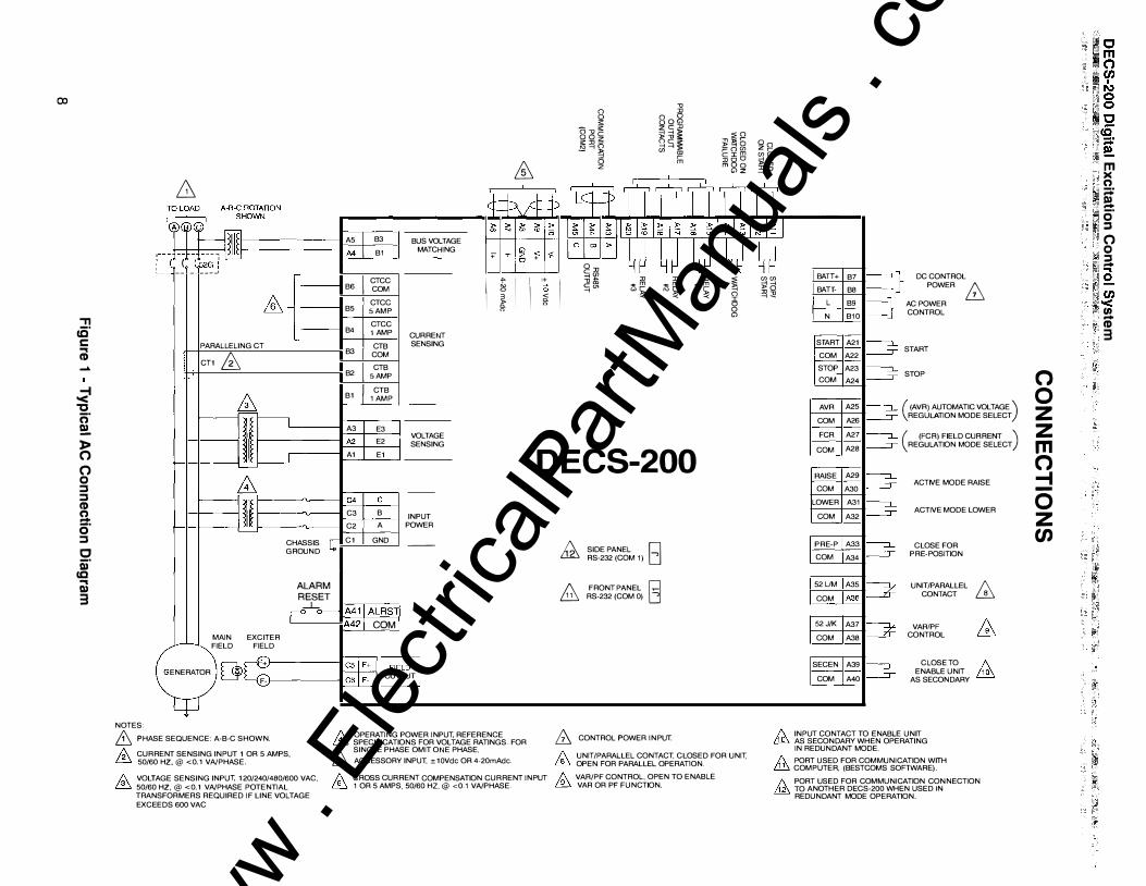
6 PHASE SEQUENCE: A-B-C SHOWN. 1\ OPERATING POWER INPUT, REFERENCE
0 1 '" 4� 4� 4� 4J )> §II< <f' io
+
��
I I I+
I =rig; :IJ :IJ :IJ � I '=�"' ,.m ,.m ,.m
0 "'� "� �� � 0 I 0 0 "'
DECS-200
& SIDE PANEL El RS-232 (COM 1) -,
g FRONT PANEL [§] RS-232 (COM 0) -,
ffi CONTROL POWER INPUT.
/:.. CURRENT SENSING INPUT 1 OR 5 AMPS, [3 50/60 HZ,@ <0.1 VA/PHASE.
� SPECIFICATIONS FOR VOLTAGE RATINGS. FOR SINGLE PHASE OMIT ONE PHASE. & ACCESSORY INPUT, ± 1 OVdc OR 4-20mAdc.
1\ UNIT/PARALLEL CONTACT, CLOSED FOR UNIT, ill OPEN FOR PARALLEL OPERATION.
/). VOLTAGE SENSING INPUT, 120/240/480/600 VAG, � 50/60 HZ,@ <0.1 VA/PHASE POTENTIAL TRANSFORMERS REQUIRED IF LINE VOLTAGE EXCEEDS 600 VAG
/:.. CROSS CURRENT COMPENSATION CURRENT INPUT � VAR/PF CONTROL , OPEN TO ENABLE � 1 OR 5 AMPS, 50/60 HZ,@ <0.1 VA/PHASE. ill VAR OR PF FUNCTION.
4� en en BATT+ B7
�d BATT- B8 -;::E L B9
N B10
START A21
COM A22
STOP A23
COM A24
AVA A25
COM A26
FCR A27
COM A28
RAISE A29
COM A30
LOWER A31
COM A32
PRE-P A33
COM A34
52UM A35
COM I A36
52J/K A37
COM A38
SECEN A39
COM A40
} DC CONTROL POWER B
AC POWER CONTROL
START
STOP
( (AVA) AUTOMATIC VOLTAGE ) REGULATION MODE SELECT
( (FCR) FIELD CURRENT ) REGULATION MODE SELECT
ACTIVE MODE RAISE
ACTIVE MODE LOWER
CLOSE FOR PRE-POSITION
UNIT/PARALLEL CONTACT ffi
VARIPF f\ CONTROL ffi
CLOSE TO f\ ENABLE UNIT � AS SECONDARY
1\ INPUT CONTACT TO ENABLE UNIT i!fl'> AS SECONDARY WHEN OPERATING IN REDUNDANT MODE.
1\ PORT USED FOR COMMUNICATION WITH � COMPUTER, (BESTCOMS SOFTWARE).
1\ PORT USED FOR COMMUNICATION CONNECTION M TO ANOTHER DECS-200 WHEN USED IN REDUNDANT MODE OPERATION.
0 0 z z m 0 -1 -
0 z C/)
m >< () ;:::;: � 0 :::J 0
'� 0 ad :I �i:, ... 1£ 1(/) lith< Fl U1 ;:, CD'
3
www . El
ectric
alPar
tMan
uals
. com
DECS-200 Digital Excitation Control System
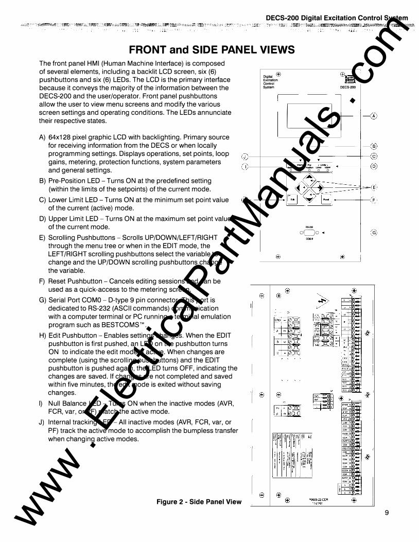
FRONT and SIDE PANEL VIEWS The front panel HMI (Human Machine Interface) is composed of several elements, including a backlit LCD screen, six (6) pushbuttons and six (6) LEOs. The LCD is the primary interface because it conveys the majority of the information between the DECS-200 and the user/operator. Front panel pushbuttons allow the user to view menu screens and modify the various screen settings and operating conditions. The LEOs annunciate their respective states.
A) 64x1 28 pixel graphic LCD with backlighting. Primary source for receiving information from the DECS or when locally programming settings. Displays operations, set points, loop gains, metering, protection functions, system parameters and general settings.
Digital I±'J I±'J�;:;;) Excitation asS. Control System DECS-200
D +-t---------+--A
,-----------1------i B ,-----------1------iC
Null Internal Pre- r UmiB, Balance ll'addng Poeltlon �· uwer 0 0 0 0 0
-----+-----i D
B) Pre-Position LED- Turns ON at the predefined setting
(within the limits of the setpoints) of the current mode. � �:'----<11�---+---�3-�E C) Lower Limit LED- Turns ON at the minimum set point value H r----t-------+ G ------+�CF.
of the current (active) mode. ="--------"=
D) Upper Limit LED- Turns ON at the maximum set point value of the current mode.
E) Scrolling Pushbuttons- Scrolls UP/DOWN/LEFT/RIGHT through the menu tree or when in the EDIT mode, the LEFT/RIGHT scrolling pushbuttons select the variable to change and the UP/DOWN scrolling pushbuttons change
the variable.
F) Reset Pushbutton- Cancels editing sessions and can be used as a quick-access to the metering screen.
G) Serial Port COMO- D-type 9 pin connector. This port is dedicated to RS-232 (ASCII commands) communication with a computer terminal or PC running a terminal emulation program such as BESTCOMS TM .
H) Edit Pushbutton- Enables settings changes. When the EDIT pushbutton is first pushed, an LED on the pushbutton turns ON to indicate the edit mode is active. When changes are complete (using the scrolling pushbuttons) and the EDIT pushbutton is pushed again, the LED turns OFF, indicating the changes are saved. If changes are not completed and saved within five minutes, the edit mode is exited without saving changes.
I) Null Balance LED- Turns ON when the inactive modes (AVR, FCR, var, or PF) match the active mode.
J) Internal tracking LED- All inactive modes (AVR, FCR, var, or
PF) track the active mode to accomplish the bumpless transfer when changing active modes.
Figure 2 - Side Panel View
R�232
oQo +--------t----( G
ON.'OF:::
�;: �� RLY2 ::; RLY2 � RlY3 <t; RLYa �
FCR 't '""' AAISEl!!
'"" " PRE·PfS '"" ' "'" ' COM ' ""'' "'"' SECEN!!: """ ALAST)J: COM •
1! : � I� c �
9 www . El
ectric
alPar
tMan
uals
. com
Front view
Top view
10
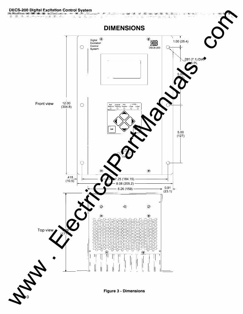
12.00 (304.8)
.41 �;-(10.5)
0
0
Digital � Excitation Control System
DIMENSIONS
Cl
Null Internal Pre- r limits, Balance Trackmg Position Lower Upper 0 0 0 0 0
RS-232 oCJo
COMJ1
��B .,!::::1
DECS-200 �
1----------- 7.25 (184.15) --------i
I_ 1.00 (25.4)
��81 (7.1) DIA. 6 PL
5.00 (127)
5.00 (127)
1------------ 8.08 (205.2) _______ ____, 1.1+---------- -------.1· 1 0.91
---.------ 'r:;=======6.=26=(1= 59=)::=-=_=_=_=_=_= -= -= -.j=;:i.l (23.1) r---
6.76 (171.7)
=
Figure 3 - Dimensions www . El
ectric
alPar
tMan
uals
. com
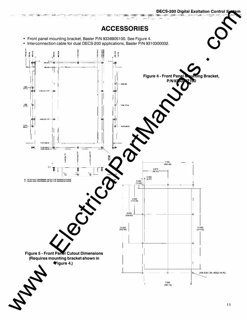
ACCESSORIES • Front panel mounting bracket, Basler P/N 9336905100. See Figure 4. • Interconnection cable for dual DECS-200 applications, Basler P/N 9310300032.
� � CD � § � L
1_0 0 .250(6.4 )
"' ,. .� II
) .985{25
4.750(12.1)TYP
9.250(2.4)TYP
13.015(330.6)
13.750{349.3) 141XXl(355.6)
-
-
@-
� �
B.) .187 DIA. HOLE, COUNTERSINK .342 DIA. X 100'
NEARSIDE (6 PlACES) C.) .156 DIA. HOLE, COUNTERSINK .281 DIA X 100' NEARSIDE (6 PLACES}
� " �� � n � � �� ;
I I II -· -$'
I -$
r -$-� �
Figure 5 - Front Panel Cutout Dimensions (Requires mounting bracket shown in
Figure 4.)
0
D2981·24COR 11-2Hl1)
Figure 4 - Front Panel Mounting Bracket, P /N 93601 071 00
7.750 �
I (465.48) (�aa��l�
0.250
0.560 (14 22)
!'17
�(6 35)
� �
4.500 (114.30) o:.-:.L. �
.500 13 (34 2.90)
� �
12.3 80 45) (314.
�r-�:_j�4)DIA.HOLE(10PL)
L-,?.250
(184.15)
11 www . El
ectric
alPar
tMan
uals
. com
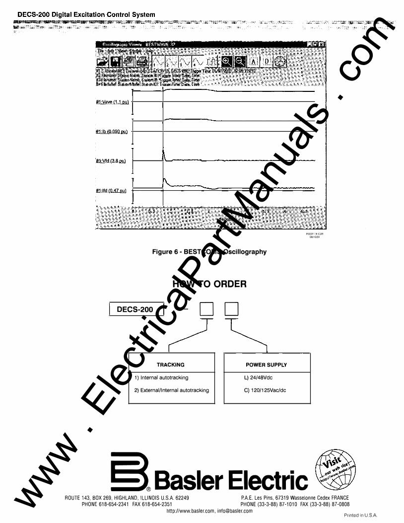
#1:Vave (1.1 pu)
#1 :lb (0.090 pu)
#1:Vfd {3.8 ou) 1\
r\ #1 :lfd {0.47 pu)
Figure 6 - BESTCOMS Oscillography
HOW TO ORDER
DECS-200 DO
? TRACKING POWER SUPPLY
1) Internal autotracking L) 24/48Vdc
2) External/Internal autotracking C) 120/125Vac/dc
POOD7-l8CDR 08/10/01
§®Basler Electric ROUTE 143, BOX 269, HIGHLAND, ILLINOIS U.S.A. 62249 P.A.E. Les Pins, 67319 Wasselonne Cedex FRANCE
PHONE 618-654-2341 FAX 618-654-2351 PHONE (33-3-88) 87-1010 FAX (33-3-88) 87-0808 http://www.basler.com, [email protected] Printed in U.S.A. www .
Elec
tricalP
artM
anua
ls . c
om