Embed Size (px)
Citation preview
.. .. II.. �
BE1-1051
OVERCURRENT
PROTECTION
SYSTEM I
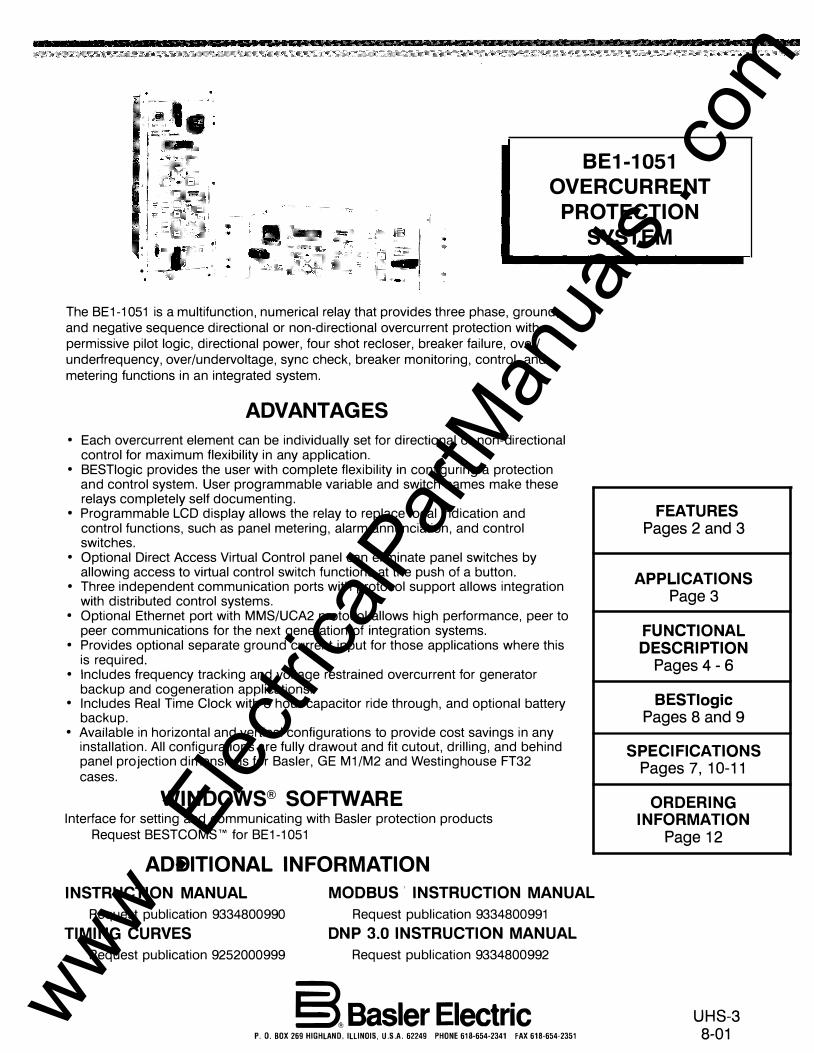
The BE1-1 051 is a multifunction, numerical relay that provides three phase, ground, and negative sequence directional or non-directional overcurrent protection with permissive pilot logic, directional power, four shot recloser, breaker failure, over/ underfrequency, over/undervoltage, sync check, breaker monitoring, control, and metering functions in an integrated system.
ADVANTAGES
• Each overcurrent element can be individually set for directional or non-directional control for maximum flexibility in any application.
• BESTiogic provides the user with complete flexibility in configuring a protection and control system. User programmable variable and switch names make these relays completely self documenting.
• Programmable LCD display allows the relay to replace local indication and control functions, such as panel metering, alarm annunciation, and control switches.
• Optional Direct Access Virtual Control panel can eliminate panel switches by allowing access to virtual control switch functions at the push of a button.
• Three independent communication ports with protocol support allows integration with distributed control systems.
• Optional Ethernet port with MMS/UCA2 protocol allows high performance, peer to peer communications for the next generation of integration systems.
• Provides optional separate ground current input for those applications where this is required.
• Includes frequency tracking and voltage restrained overcurrent for generator backup and cogeneration applications.
• Includes Real Time Clock with 8 hour capacitor ride through, and optional battery backup.
• Available in horizontal and vertical configurations to provide cost savings in any installation. All configurations are fully drawout and fit cutout, drilling, and behind panel projection dimensions for Basler, GE M1/M2 and Westinghouse FT32 cases.
WINDOWS® SOFTWARE Interface for setting and communicating with Basler protection products
Request BESTCOMS™ for BE1-1051
ADDITIONAL INFORMATION
INSTRUCTION MANUAL
Request publication 9334800990
TIMING CURVES
Request publication 9252000999
MODBUS I INSTRUCTION MANUAL
Request publication 9334800991
DNP 3.0 INSTRUCTION MANUAL
Request publication 9334800992
§l Basler Electric P. 0. BOX 269 HIGHLAND. ILLINOIS, U.S.A. 62249 PHONE 618-654-2341 FAX 618-654-2351
FEATURES Pages 2 and 3
APPLICATIONS Page 3
FUNCTIONAL DESCRIPTION
Pages 4-6
BESTiogic Pages 8 and 9
SPECIFICATIONS Pages 7, 10-11
ORDERING INFORMATION
Page 12
UHS-3 8-01 www .
Elec
tricalP
artM
anua
ls . c
om
BE1-1051
FEATURES
2
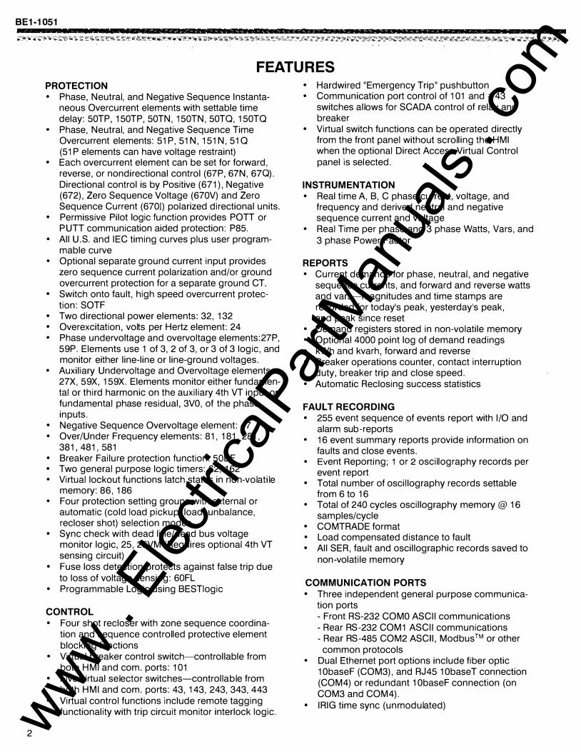
PROTECTION • Phase, Neutral, and Negative Sequence Instanta
neous Overcurrent elements with settable time delay: 50TP, 150TP, 50TN, 150TN, 50TQ, 150TQ Phase, Neutral, and Negative Sequence Time Overcurrent elements: 51 P, 51 N, 151 N, 51 Q (51 P elements can have voltage restraint)
• Each overcurrent element can be set for forward, reverse, or nondirectional control (67P, 67N, 670). Directional control is by Positive (671), Negative (672), Zero Sequence Voltage (670V) and Zero Sequence Current (6701) polarized directional units.
• Permissive Pilot logic function provides POTT or PUTT communication aided protection: P85.
• All U. S. and IEC timing curves plus user programmable curve
• Optional separate ground current input provides zero sequence current polarization and/or ground overcurrent protection for a separate ground CT.
• Switch onto fault, high speed overcurrent protec-tion: SOTF
• Two directional power elements: 32, 132 • Overexcitation, volts per Hertz element: 24 • Phase undervoltage and overvoltage elements: 27P,
59P. Elements use 1 of 3, 2 of 3, or 3 of 3 logic, and monitor either line-line or line-ground voltages.
• Auxiliary Undervoltage and Overvol tage elements: 27X, 59X, 159X. Elements monitor either fundamental or third harmonic on the auxiliary 4th VT input or fundamental phase residual, 3VO, of the phase inputs.
• Negative Sequence Overvoltage element: 47 • Over/Under Frequency elements: 81, 181, 281,
381, 481, 581 • Breaker Failure protection function: 50BF • Two general purpose logic timers: 62, 162 • Virtual lockout functions latch states in non-volatile
memory: 86, 186 • Four protection setting groups with external or
automatic (cold load pickup, load, unbalance, recloser shot) selection modes
• Sync check with dead line/dead bus voltage monitor logic, 25, 25VM (Requires optional 4th VT sensing circuit)
• Fuse loss detection protects against false trip due to loss of voltage sensing: 60FL
• Programmable Logic using BESTiogic
CONTROL • Four shot recloser with zone sequence coordina
tion and sequence controlled protective element blocking functions
• Virtual breaker control switch-controllable from both HMI and com. ports: 101
• Five virtual selector switches-controllable from both HMI and com. ports: 43, 143, 243, 343, 443
• Virtual control functions include remote tagging functionality with trip circuit monitor interlock logic.
• Hardwired "Emergency Trip" pushbutton • Communication port control of 1 01 and #43
switches allows for SCADA control of relay and breaker
• Virtual switch functions can be operated directly from the front panel without scrolling the HMI when the optional Direct Access Virtual Control panel is sel ected.
INSTRUMENTATION • Real time A, B, C phase current, voltage, and
frequency and derived neutral and negative sequence current and voltage
• Real Time per phase and 3 phase Watts, Vars, and 3 phase Power Factor
REPORTS • Current demands for phase, neutral , and negative
sequence currents, and forward and reverse watts and vars-magnitudes and time stamps are recorded for today's peak, yesterday's peak, and peak since reset
• Demand registers stored in non-volatile memory • Optional 4000 point log of demand readings • kWh and kvarh, forward and reverse • Breaker operations counter, contact interruption
duty, breaker trip and close speed. • Automatic Reclosing success statistics
FAULT RECORDING • 255 event sequence of events report with 1/0 and
alarm sub-reports • 16 event summary reports provide information on
faults and close events. • Event Reporting; 1 or 2 oscillography records per
event report • Total number of oscillography records settable
from 6 to 16 • Total of 240 cycles oscillography memory @ 16
samples/cycle • COMTRADE format • Load compensated distance to fault • All SER, fault and oscillographic records saved to
non-volatile memory
COMMUNICATION PORTS • Three independent general purpose communica
tion ports - Front RS-232 COMO ASCII communications - Rear RS-232 COM1 ASCII communications -Rear RS-485 COM2 ASCII, Modbus™ or other
common protocols • Dual Ethernet port options include fiber optic
1 ObaseF (COM3), and RJ45 1 ObaseT connection (COM4) or redundant 1 ObaseF connection (on COM3 and COM4).
• IRIG time sync (unmodulated) www . El
ectric
alPar
tMan
uals
. com

FEATURES, continued
SELF TEST AND ALARM FUNCTIONS • Relay fail, major alarm, and minor alarm LEOs,
and fail-safe alarm output contact
PROGRAMMABLE 1/0 • Eight programmable inputs • Six programmable outputs and one dedicated
programmable alarm output
BE1 -1051
• Extensive internal diagnostics monitor all internal functions of the relay • Output 1 and 6 are high speed (1 /4 cycle nominal)
• More than 20 additional alarm pointsprogrammable for major or minor priority Including:
• Output 6 is Form C
HARDWARE FEATURES • Three mounting configurations - Phase current, and forward and reverse watt and
var demand alarm - Neutral and negative sequence unbalance
demand alarms
- MX Vert: M1, M2/FT31, FT32 size, fully drawout MX Horiz: panel or 19" rack mount, fully drawout
- Three breaker alarm points programmable for slow trip, interruption duty threshold, or operations counter
- Trip circuit voltage and continuity monitor - Close circuit monitor via BESTiogic - Voltage Min. and Max. alarms
0 D I I 0 Emergency
Trip Virtual Relay Mtnor Major
� PoQer �Q TrQbte A�m �Om
I 0'
v�o 0 � GQB 0 0
"
I
• Active CT technology for low burden and increased dynamic range
• Flash Memory for upgrading embedded programming without changing chips
• Real Time Clock with 8 hour capacitor ride through, and optional battery backup
• Integral HMI with 2x16 character display
BREAKER r,,., O G I§,
STATUS 0 0
Open Closed
G p 8 G
Redose
Enabled
Gmcod 1:"""'" Negat1ve Sequence Enabled
���:�, I" Auto
Ma11ual ��m"'" Group Select Group I
Remote [:"""'" SCADA Control Enabled
<3 0
BE1-1051
OG Overcurrent '"
Protection 0 System
OG N3 � 0
OG 3<3 0
Com!J
OG RS-232
"" ©JU::::.�@ 0
0 0
0 0
Figure 1 - Advanced HMI (Human Machine Interface) with optional Direct Access Virtual Control Panel
APPLICATIONS
The BE1-1 051 Overcurrent Protection System provides three phase, ground, and negative sequence overcurrent, voltage and frequency protection and is intended for use in any directional or non-directional overcurrent protection application. Its unique capabilities make it ideally suited for applications with the following requirements:
• Applications that require low burden to extend the linear range of CTs. • Applications that require high accuracy across a wide frequency range such as for motor, generator, and
generator step-up transformer protection or in cogeneration facilities. • Applications that require the flexibility provided by wide setting ranges, multiple setting groups, and multiple
coordination curves in one unit. • Applications that require the economy and space savings provided by a multifunction, multiphase unit. This one
unit can provide all of the protection, control, metering, and local and remote indication functions required on a
typical circuit. • Applications that require directional control and fault locating. • Transformer backup applications where overexcitation protection is required. • Applications that require communications and protocol support. • Applications where the capabilities of a digital multifunction relay are required, yet drawout construction is also
desirable. • Applications where bus protection is provided by a high speed overcurrent blocking scheme on the transformer
bus mains instead of a dedicated bus differential circuit. • Applications where the capabilities of intelligent electronic devices (lEOs) are used to decrease relay and
equipment maintenance costs. www . El
ectric
alPar
tMan
uals
. com
BE1-1051
FUNCTIONAL DESCRIPTION
4
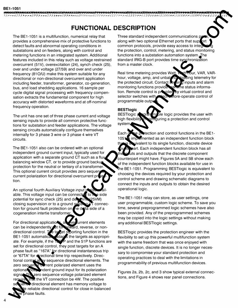
The BE1-1 051 is a multifunction, numerical relay that provides a comprehensive mix of protective functions to detect faults and abnormal operating conditions in substations and on feeders, along with control and metering functions in an integrated system. Additional features included in this relay such as voltage restrained overcurrent (51V), overexcitation (24), synch check (25), over and under voltage (27/59) and over and under frequency (81 0/U) make this system suitable for any directional or non-directional overcurrent application including feeder, transformer, generator, co-generation, bus, and load shedding applications. 16 sample per cycle digital signal processing with frequency compensation extracts the fundamental component for high accuracy with distorted waveforms and at off-nominal frequency operation.
The unit has one set of three phase current and voltage sensing inputs to provide all common protective functions for substation and feeder applications. The voltage sensing circuits automatically configure themselves internally for 3 phase 3 wire or 3 phase 4 wire VT circuits.
The BE1-1051 also can be ordered with an optional independent ground current input, typically used for application with a separate ground CT such as a flux balancing window CT, or to provide ground backup protection for the neutral or tertiary of a transformer. This optional current circuit provides zero sequence current polarization for directional overcurrent protection.
An optional fourth Auxiliary Voltage input is also available. This voltage input can be connected to line side potential for sync check (25) and dead line (25VM) closing supervision or to a ground sensing VT connection for ground fault protection on the delta side of a cogeneration intertie transformer.
For directional applications, all overcurrent elements can be independently set for forward, reverse, or nondirectional control. The target reporting function in the BE1-1 051 automatically adapts the targets as appropriate. For example, if the 150TP and the 51 P functions are set for directional control, they post targets for an A phase fault as "167A" for directional instantaneous trip or "67TA" for directional time trip respectively. Directional control is by sequence directional elements. The zero sequence current polarized element uses the optional independent ground input for its polarization signal. The zero sequence voltage polarized element requires that the VT connection be 4W. The positive sequence directional element has memory voltage to provide reliable directional control for close in balanced three phase faults.
Three standard independent communications ports, along with two optional Ethernet ports that support common protocols, provide easy access to integrating the protection, control, metering, and status monitoring functions into a substation automation system. The standard IRIG-B port provides time synchronization from a master clock.
Real time metering provides Watt, Watt-hour, VAR, VARhour, voltage, amp, and unbalance loading telemetry for the protected circuit. Contact sensing inputs and alarm monitoring functions provide real time status information. Remote control is provided by virtual control and selector switches with select-before-operate control of programmable outputs.
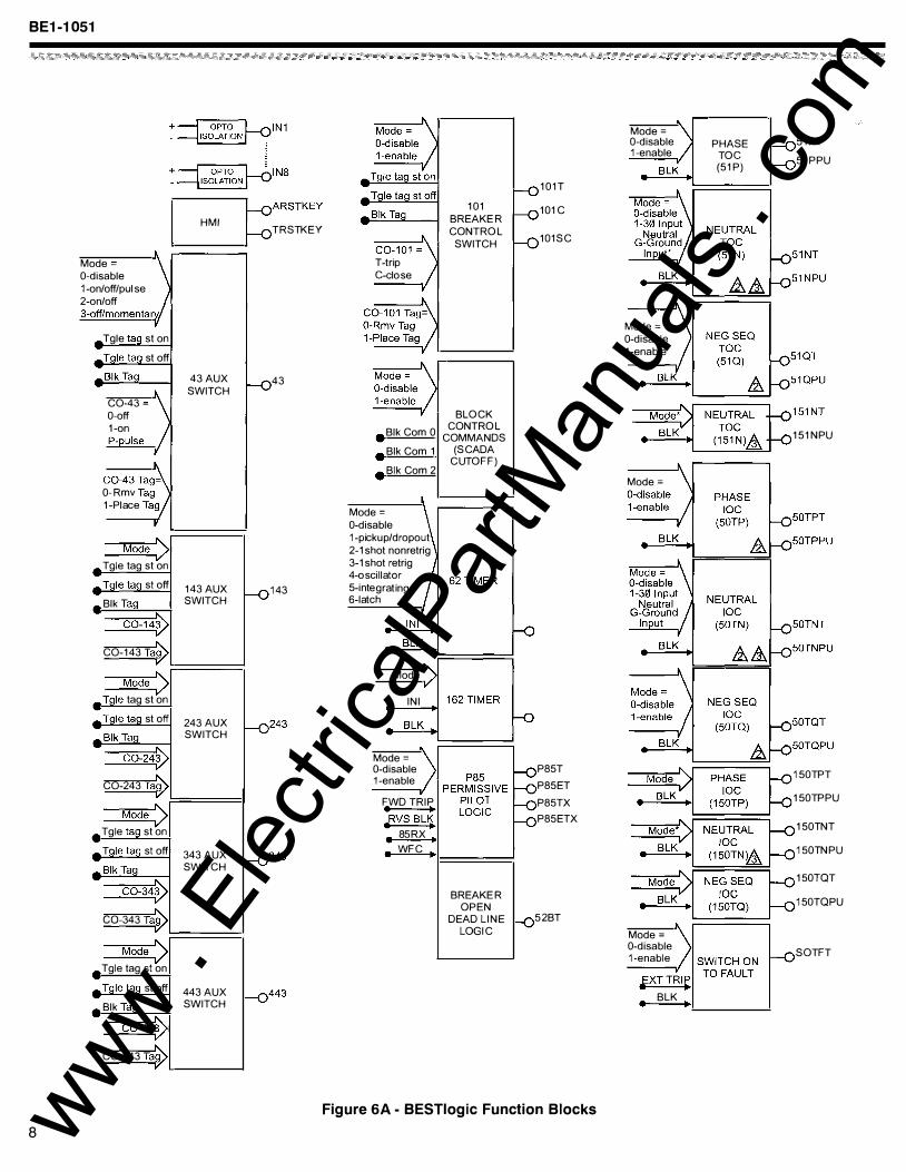
BESTiogic BESTiogic programmable logic provides the user with high flexibility in configuring a protection and control system.
Each of the protection and control functions in the BE1-
1 051 is implemented as an independent function block that is equivalent to its single function, discrete device
counterpart. Each independent function block has all the inputs and outputs that the discrete component counterpart might have. Figures 5A and 58 show each of the independent function blocks available for use in the BE1-1 051. Programming BESTiogic is equivalent to
choosing the devices required by your protection and control scheme and drawing schematic diagrams to connect the inputs and outputs to obtain the desired operational logic.
The BE1-1 051 relay can store, as user settings, one user programmable, custom logic scheme. To save you time, several preprogrammed logic schemes have also been provided. Any of the preprogrammed schemes may be copied into the logic settings without making any additional BESTiogic settings.
BESTiogic provides the protection engineer with the
flexibility to set up this powerful multifunction system
with the same freedom that was once enjoyed with
single function, discrete devices. It is no longer neces
sary to compromise your standard protection and operating practices to deal with the limitations in
programmability of previous multifunction devices.
Figures 2a, 2b, 2c, and 3 show typical external connec
tions, and Figure 4 shows rear panel connections.
www . El
ectric
alPar
tMan
uals
. com
FUNCTIONAL DESCRIPTION, continued
::�::;:::::::::::::::::::::::::::::::::+:::::�:::::::::::::::::::�sus --+-��-.----------------------------�-----+------�---------- c
r----------1 I
II(�\ 71
LINE I I I I
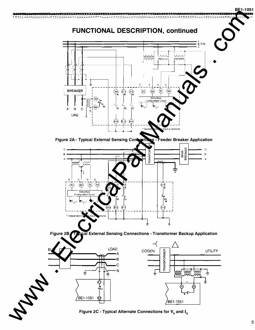
*Auxiliary Voltage input is optional.
Figure 2A- Typical External Sensing Connections - Feeder Breaker Application
c ----------�------------------���� s ------r--t-------�����H A -r��-t--------���*==F�ti
* Independent Ground Input is optional
c
B
A
Figure 2B - Typical External Sensing Connections - Transformer Backup Application
-< � LOAD UTILITY
A B c N
":"
Figure 2C- Typical Alternate Connections for Vx and IG
BE1-1051
5 www . El
ectric
alPar
tMan
uals
. com
BE1-1051
6
CONTROL
POWER
CONTROL
POWER
NOTES:
FUNCTIONAL DESCRIPTION, continued
& r---�----��----�------�----���
A2
A3 C17 - C19 - C21 - C23 -
�--._ ____ _. ______ ._ ____ �----��� &
52 TRIP
COIL
C3
OUT
C4
52 CLOSE
COIL
cs
cs
OUT
2
NOT
USED
C7
CB
OUT
3
MINOA
ALARM
C9
OUT
C10
MAJOR
ALARM
C11
C12
OUT
5
NOT USED
C13 C15
C14
NOT USED
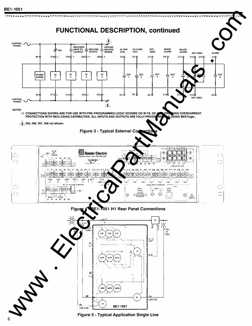
1.) CONNECTIONS SHOWN ARE FOR USE WITH PRE-PROGRAMMED LOGIC SCHEME OC-W-79. OC-W-79 PROVIDES OVERCURRENT PROTECTION WITH RECLOSING CAPABILITIES. ALL INPUTS AND OUTPUTS ARE FULLY PROGRAMMABLE USING BESTiogic.
& INS, INS, IN7, INS not shown.
Figure 3 - Typical External Connections
§.Basler Electric Hlghland,lllmois USA (618) 654-2341
LIN1 r L,N,I l1N3J LIN4j
liN5J LIN6- iiN7J LINSJ I RELAY INPUT CONTACTS
COM1 !;X COM3 � COM4 RS-232 AJ45
© ©/§@ 0 0 LQJ___j L1 WARNING
Figure 4- BE1-1051 H1 Rear Panel Connections
Figure 5 - Typical Application Single Line
ALARM
C1
C2
OUT
A
I 0' 0
o. 0:
www . El
ectric
alPar
tMan
uals
. com
BE1-1051
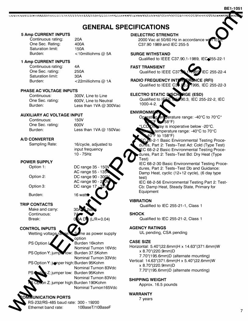
GENERAL SPECIFICATIONS 5 Amp CURRENT INPUTS
Continuous rating: One Sec. Rating: Saturation limit: Burden:
1 Amp CURRENT INPUTS Continuous rating: One Sec. rating: Saturation limit: Burden:
20A 400A 150A < 1 Omilliohms @ 5A
4A 250A 30A <22milliohms@ 1A
PHASE AC VOLTAGE INPUTS Continuous: One Sec. rating: Burden:
300V, Line to Line 600V, Line to Neutral Less than 1VA@ 300Vac
AUXILIARY AC VOLTAGE INPUT Continuous: 150V One Sec. rating: 600V Burden: Less than 1VA@ 150Vac
A/D CONVERTER Sampling Rate:
POWER SUPPLY Option 1:
Option 2:
Option 3:
Burden:
TRIP CONTACTS Make and carry: Continuous: Break:
CONTROL INPUTS
16/cycle, adjusted to input frequency 10 - 75Hz
DC range 35 - 150V AC range 55 - 135V DC range 90 - 300V AC range 90 - 270V DC range 17 - 32V
16 watts
30A (0.2sec) ?A 0.3A DC (L/R=0.04)
Wetting voltage range: Same as power supply option
PS Option L: Burden 16kohm Nominal Turnon 16Vdc
PS Option Y; jumper low: Burden 37.5Kohm Nominal Turnon 33Vdc
PS Option Y: jumper high: Burden 95Kohm Nominal Turnon 83Vdc
PS Option Z; jumper low: Burden 95Kohm Nominal Turnon 83Vdc
PS Option Z; jumper high: Burden 190Kohm Nominal Turnon165Vdc
COMMUNICATION PORTS RS-232/RS-485 baud rate: 300 - 19200 Ethernet band rate: 1 OBaseT/1 OBaseF
DIELECTRIC STRENGTH 2000 Vac at 50/60 Hz in accordance with IEEE C37.90 1989 and IEC 255-5
SURGE WITHSTAND Qualified to IEEE C37.90.1-1989, IEC 255-22-1
FAST TRANSIENT Qualified to IEEE C37.90.1-1989, IEC 255-22-4
RADIO FREQUENCY INTERFERENCE (RFI) Qualified to IEEE C37.90.2-1995, IEC 255-22-3
ELECTRO STATIC DISCHARGE (ESD) Qualified to IEEE C37.90.3, IEC 255-22-2, IEC 1000-4-2.
ENVIRONMENT Operating temperature range: -40°C to 70°C*
(-40°F to 158°F) *LCD Display is inoperative below -20°C. Storage temperature range: -40°C to 70°C
(-40°F to 158°F) IEC 68-2-1 Basic Environmental Testing Procedures, Part 2: Tests-Test Ad: Cold (Type Test) IEC 68-2-2 Basic Environmental Testing Procedures, Part 2: Tests-Test Bd: Dry Heat (Type Test) IEC 68-2-30 Basic Environmental Testing Procedures, Part 2: Tests-Test Db and Guidance: Damp Heat, cyclic (12+ 12 cycle), (6 day type test) IEC 68-2-56 Environmental Testing Part 2: TestCb: Damp Heat, Steady State, Primary for Equipment
VIBRATION Qualified to IEC 255-21-1, Class 1
SHOCK Qualified to IEC 255-21-2, Class 1
AGENCY RATINGS UL pending, CSA pending
CASE SIZE Horizontal: 5.40"(22.6mm)H x 14.63"(371.6mm)W
x 8.70"(220.9mm)D 7 .70"(195.6mm)D (alternate mounting)
Vertical: 14.63"(371.6mm)H x 5.40"(22.6mm)W x 8.70"(220.9mm)D 7.70" (195.6mm)D (alternate mounting)
SHIPPING WEIGHT Approx. 16.5 pounds
WARRANTY 7 years
7 www . El
ectric
alPar
tMan
uals
. com
BE1-1051
8
+ �IN1
-� + �IN8
� Mode- \ 0-disable 1-on/off/pulse lrv/ 2-on/off 3-off/momenta
, _ Tgle tag st on
Tqle taq st off
_ Bik Tag -
� C0-43- \ 0-off 1-on I P-pulse
� C0-43 Tag
,�
0-Rmv Tag 1-Piace Tagj
v
Mode > _ Tgle tag st on -
Tqle taq st off
Blk Taq
C0-14:? C0-143 Tae>
Mode > Tgle tag st on
Tqle taq st off
_ Bik Tag_ -
C0-24:? C0-243 Tae>
Mode > Tgle tag st on
T qle taq st off
_ Bik Tag -
C0-34:? co-343 Taw
Mode > Tgle tag st on
_ Tgle tag st off -
Blk Taq
C0-44:? C0-443 Tae>
- �
HMI
43 AUX SWITCH
143 AUX SWITCH
243 AUX SWITCH
343 AUX SWITCH
443 AUX SWITCH
�RSTKEY
TRSTKEY
f--o 43
-o 143
243 f-0;
343 -o;
443 -Q'
T -trip G-elose
Blk Com 0
Blk Com 1
Blk Com 2
Mode= 0-disable 1-pickup/dropout 2-1 shot nonretrig 3-1 shot retrig 4-oscillator 5-integ rating 6-latch
•
Mode
INI
Mode= 0-disable 1-enable
FWD TRIP • •
•RVS BL� 85RX
• WFC •
101 BREAKER
CONTROL SWITCH
BLOCK CONTROL
COMMANDS (SCADA
CUTOFF)
BREAKER OPEN
DEAD LINE LOGIC
101T
101C
101SC
P85T
P85ET
P85TX
P85ETX
52BT
Figure 6A - BESTiogic Function Blocks
Mode= 0-disable 1-enable
Mode= 0-disable 1-enable
Mode=
Mode= 0-disable 1-enable
1pTTRI� • BLK •
PHASE TOG (51P)
51PT
51PPU
151NPU
150TPT
150TPPU
150TNT
150TNPU
150TQT
150TQPU
SOTFT
www . El
ectric
alPar
tMan
uals
. com
Mode= 0-disable 1-1 of 3 2-2 of 3 3-3 of 3
Mode= 0-disable 1-1st harm Aux VT 2-calc 3Vo 3-3rd harm Aux V
Mode= 0-disable 1-1 of 3 2-2 of 3 3-3 of 3
Mode= 0-disable
•
1-1st harm Aux VT 2-calc 3Vo 3-3rd harm Aux V
•
Mode=
•
•
•
159XT
159XPU
81T
BE1-1051
VT FUSE Mode= 79P
LOSS 60FL 0-disable 79C (60FL) 1-Power Up to LO
2-Power Up to Close 79RNG
PI 79 79LO SGO Rl RECLOSER
ACTIVE STAT
79R SG1 SETTING WAIT
GROUP LO 79SCB CONTROL
SG2
SG3 ALARMS
VOAO �
CO-OUTA= \ GT VIRTUAL 0 - off OUTPUT
LOCKOUT 1 - on LOGIC (86) P - pulse I RESET L - logic
v
vo10 =ET1 186 OUTPUT
CO-OUT,1, LOGIC
Mode= 0-disable CKTMON V02 =ET2 1-enable '-"" OUTPUT
CO-OUT2 LOGIC --v
V03 =ET3 '-' OUTPUT
� LOGIC SYNC CHECK CO-OUT3
WITH --v VOLTAGE V04 � =ET4 MONITOR '-' OUTPUT (25)
LOGIC .... CO-OUT4 --v
VOLTS PER HERTZ vas�
ET5 (24) '-' OUTPUT
CO-OUTS LOGIC
Optional --v
UCA2 V06�
t" Protocol OUTPUT GOOSE " LOGIC 1 CO-OUT6
"
VO?O Mode= 0-disable 1-enable V0176
BFT
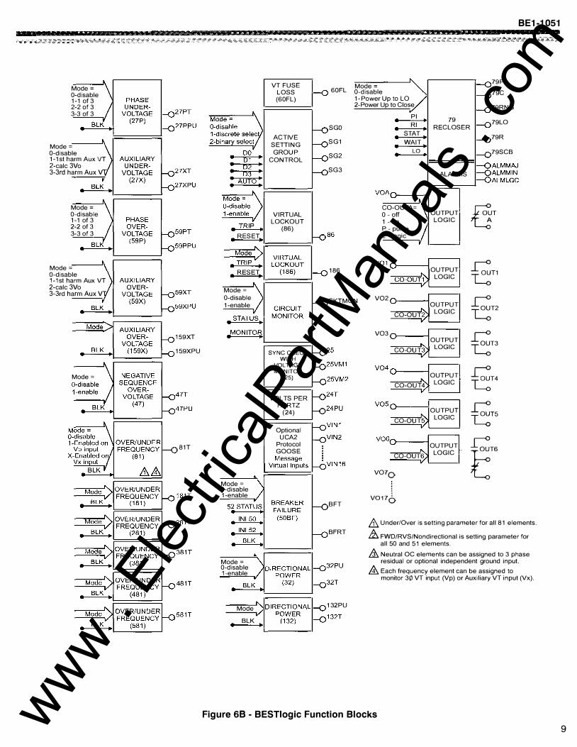
& Under/Over is setting parameter for all 81 elements.
BFRT ,&. FWD/RVS/Nondirectional is setting parameter for all 50 and 51 elements.
,& Neutral OC elements can be assigned to 3 phase Mode= residual or optional independent ground input. 0-disable ,&. Each frequency element can be assigned to 1-enable
monitor 30 VT input (Vp) or Auxiliary VT input (Vx) .
Mode 132PU
• BLK
Figure 68 - BESTiogic Function Blocks
9 www . El
ectric
alPar
tMan
uals
. com
BE1-1051
PERFORMANCE SPECIFICATIONS
10
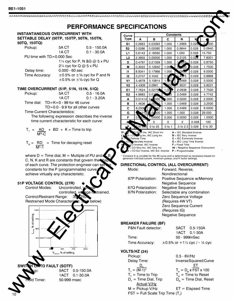
INSTANTANEOUS OVERCURRENT WITH SETTABLE DELAY (50TP, 150TP, SOTN, 150TN, SOTQ, 150TQ)
Pickup: 5A CT 1A CT
0.5 - 150.0A 0.1 - 30.0A
PU time with TD=O.OOO Sec
Delay time:
1% eye for P, N &G @ 5 x PU 2% eye for Q @ 5 x PU 0.000 - 60 sec
Time Accuracy: ±0.5% or ±%eye for P and N ±0.5% or±% eye for Q
TIME OVERCURRENT (51P, 51 N, 151N, 510) Pickup: 5A CT 0.5 - 16.0A
1A CT 0.1 - 3.20A Time dial: TD=K=O - 99 for 46 curve
TD=O.O - 9.9 for all other curves Time-Current Characteristics:
The following expression describes the inverse time current characteristic for each curve:
T T = AD + BD + K = Time to trip MN -C
T R = RD Time for decaying reset M2-1
where D = Time dial, M = Multiple of PU and A, B, C, N, K and R are constants that govern the shape of each curve. The protection engineer can set the constants for the P (programmable} curve to achieve virtually any characteristic.
51 P VOLTAGE CONTROL (27R) Control Modes: Uncontrolled, voltage
controlled, voltage restrained. Control/Restraint Range: 30 - 250V Restrained Mode Characteristic: (see below)
1QQO_t, --------------------------------
Ol c -� 75%-----------------------(/)
� c. SO'Yc ---------------t -�
25% V, • .,,,, % of setting
SWITCH ONTO FAULT (SOTF) Pickup: 5ACT 0.5-150.0A
1 ACT 0.1-30.0A Hold Timer: 50-999 msec
Curve Constants Type A B
S1 0.2663 0.03393 S2 0.0286 0.02080 L1 5.6143 2.18592 L2 2.3955 0.00000 D 0.4797 0.21359 M 0.3022 0.12840 11 8.9341 0.17966 12 0.2747 0.1042 V1 5.4678 0.10814 V2 4.4309 0.0991 E1 7.7624 0.02758 E2 4.9883 0.0129 A 0.01414 0.00000 B 1.4636 0.00000 c 8.2506 0.00000 G 12.1212 0.00000 F 0.0000 1.00000
46 * 0 p 0 to 600 0 to 25
S1, S2 = CO Short lnv, lAC Short lnv
L 1, L2 = CO Long lnv, lAC Long lnv D = CO Definite Time
M = CO Moderately Inverse 11, 12 =CO Inverse, lAC Inverse V1, V2 =CO Very lnv, lAC Very lnv
c 1.000 1.000 1.000 1.000 1.000 1.000 1.000 1.000 1.000 1.000 1.000 1.000 1.000 1.000 1.000 1.000 0.000
0 0 to 1
E1, E2 =CO Ext Inverse, lAC Ext. Inverse
N K 1.2969 0.028 0.9844 0.028 1.000 0.028 0.3125 0.028 1.5625 0.028 0.5000 0.028 2.0938 0.028 0.4375 0.028 2.0469 0.028 1.9531 0.028 2.0938 0.028 2.0469 0.028 0.0200 0.028 1.0469 0.028 2.0469 0.028 1.000 0.028 0.0000 0.028
2 0.028 .5 to 2.5 0.028
A = IEC Standard Inverse B = IEC Very Inverse
R 0.5000 0.0940
15.750 7.8001 0.8750 1.7500 9.0000 0.8868 5.5000 5.8231 7.7500 4.7742 2.0000 3.2500 8.0000
29.000 1.0000
100 0 to 30
C = IEC Extremely Inverse
G = IEC Long Time Inverse F = Fixed Time 46 = Negative Sequence Overcurrent
P = Programmable
• Constant A is variable for the 46 curve and is determined as necessary based on generator full load current, minimum pickup, and K factor settings.
DIRECTIONAL CONTROL (ALL OVERCURRENT) Mode: Forward, Reverse,
Nondirectional 67P Polarization: Positive Sequence w/Memory
Negative Sequence 670 Polarization: Negative Sequence 67N Polarization: Selectable any combination
Zero Sequence Voltage (Requires 4W VT) Zero Sequence Current (Requires IG) Negative Sequence
BREAKER FAILURE (BF) P&N Fault detector: 5ACT 0.5-150A
1 ACT 0.1-30A 50 - 999mSec Time:
Time Accuracy:
VOLTS/HZ (24) Pickup: Delay Time:
.Jh_ TT = (M-1)2 TT = Time to Trip DT = Time Dial, Trip
Actual V/Hz
±0.5% or +1% eye I-% eye
0.5 - 6V/Hz Inverse Squared Curve
ET T R = DR X FST X 1 00 T R = Time to Reset DR = Time Dial, Reset
M = Pickup V/Hz ET = Elapsed Time FST = Full Scale Trip Time (TT} www .
Elec
tricalP
artM
anua
ls . c
om
BE1-1051
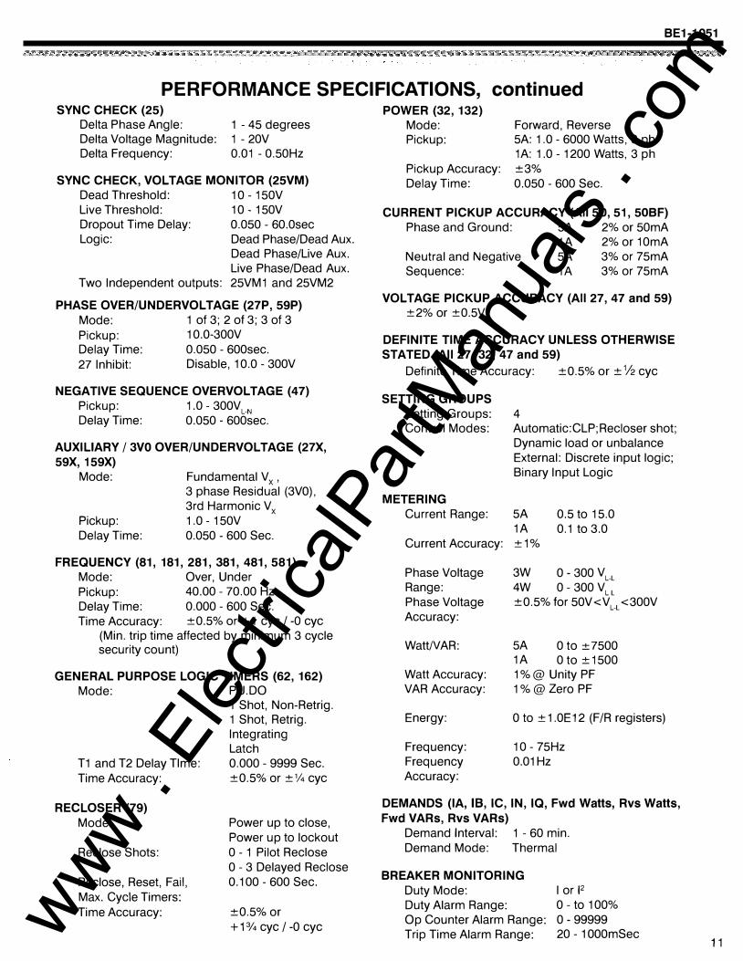
PERFORMANCE SPECIFICATIONS, continued SYNC CHECK (25)
Delta Phase Angle: Delta Voltage Magnitude:
1 - 45 degrees 1 - 20V
Delta Frequency: 0.01 - 0.50Hz
SYNC CHECK, VOLTAGE MONITOR (25VM) Dead Threshold: 10 - 150V Live Threshold: 10- 150V Dropout Time Delay: 0.050 - 60.0sec Logic: Dead Phase/Dead Aux.
Dead Phase/Live Aux. Live Phase/Dead Aux.
Two Independent outputs: 25VM1 and 25VM2
PHASE OVER/UNDERVOLTAGE (27P, 59P) Mode: 1 of 3; 2 of 3; 3 of 3 Pickup: 1 0.0-300V Delay Time: 0.050 - 600sec. 27 Inhibit: Disable, 10.0 - 300V
NEGATIVE SEQUENCE OVERVOLTAGE (47) Pickup: 1.0 - 300VL·N Delay Time: 0.050- 600sec.
AUXILIARY I 3VO OVER/UNDERVOLTAGE (27X, 59X, 1 59X)
Mode:
Pickup: Delay Time:
Fundamental V x , 3 phase Residual (3VO), 3rd Harmonic Vx 1.0 - 150V 0.050 - 600 Sec.
FREQUENCY (81, 181, 281, 381, 481, 581) Mode: Over, Under Pickup: 40.00 - 70.00 Hz Delay Time: 0.000 - 600 Sec. Time Accuracy: ±0.5% or +1 eye I -0 eye
(Min. trip time affected by minimum 3 cycle security count)
GENERAL PURPOSE LOGIC TIMERS (62, 162) Mode: PU.DO
T1 and T2 Delay Time: Time Accuracy:
RECLOSER (79) Mode:
Reclose Shots:
Reclose, Reset, Fail, Max. Cycle Timers: Time Accuracy:
1 Shot, Non-Retrig. 1 Shot, Retrig. Integrating Latch 0.000 - 9999 Sec.
±0.5% or ±% eye
Power up to close, Power up to lockout 0 - 1 Pilot Reclose 0 - 3 Delayed Reclose 0.100 - 600 Sec.
±0.5% or +1% eye I -0 eye
POWER (32, 132) Mode: Pickup:
Pickup Accuracy: Delay Time:
Forward, Reverse 5A: 1.0 - 6000 Watts, 3 ph 1A: 1.0 - 1200 Watts, 3 ph
±3% 0.050 - 600 Sec.
CURRENT PICKUP ACCURACY (All 50, 51 , 50BF) Phase and Ground: 5A 2% or 50mA
1A 2% or 10mA Neutral and Negative Sequence:
5A 3% or 75mA 1A 3% or 75mA
VOLTAGE PICKUP ACCURACY (All 27, 47 and 59) ±2% or ±0.5V
DEFINITE TIME ACCURACY UNLESS OTHERWISE STATED (All 27, 32, 47 and 59)
Definite Time Accuracy: ±0.5% or ±%eye
SETTING GROUPS Setting Groups: Control Modes:
METERING Current Range:
Current Accuracy:
Phase Voltage Range: Phase Voltage Accuracy:
WattNAR:
Watt Accuracy: VAR Accuracy:
Energy:
Frequency: Frequency Accuracy:
4 Automatic:CLP; Recloser shot; Dynamic load or unbalance External: Discrete input logic; Binary Input Logic
5A 0.5 to 15.0 1A 0.1 to 3.0 ±1%
3W 0- 300 VL·L 4W 0 - 300 VLL
±0.5% for 50V<VL·L <300V
5A 0 to ±7500 1A 0 to ±1500 1%@ Unity PF 1%@ Zero PF
0 to ± 1.0E12 (F/R registers)
10 - 75Hz 0.01 Hz
DEMANDS (lA, 18, IC, IN, IQ, Fwd Watts, Rvs Watts, Fwd VARs, Rvs VARs)
Demand Interval: 1 - 60 min. Demand Mode: Thermal
BREAKER MONITORING Duty Mode: Duty Alarm Range: Op Counter Alarm Range: Trip Time Alarm Range:
I or F 0 - to 100% 0- 99999 20 - 1 OOOmSec
11 www . El
ectric
alPar
tMan
uals
. com
BE1-1
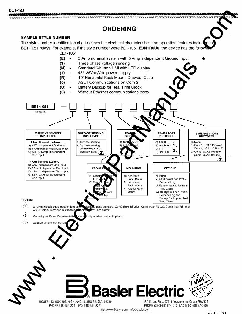
ORDERING
SAMPLE STYLE NUMBER The style number identification chart defines the electrical characteristics and operation features included in BE1-1 051 relays. For example, if the style number were BE1-1 051 E3N1 ROUO, the device has the following:
BE1-1051
BE1-1051 MODEL NO.
(E) (3) (N) (1) (R) (0) (U) (0)
CURRENT SENSING INPUT TYPE
1 Amp Nominal Systems A) W/0 Independent Gnd Input B) 1 Amp Independent Gnd Input C) SEF (0.1Amp) Independent
Gnd Input
5 Amp Nominal Systems D) W/0 Independent Gnd Input E) 5 Amp Independent Gnd Input F) 1 Amp Independent Gnd Input G) SEF (0.1Amp) Independent
Gnd Input
NOTES:
D
5 Amp nominal system with 5 Amp Independent Ground Input Three phase voltage sensing Standard 6-button HMI with LCD display 48/125VacNdc power supply 19" Horizontal Rack Mount, Drawout Case ASCII Communications on Com 2 Battery Backup for Real Time Clock Without Ethernet communications ports
D D D DODD
VOLTAGE SENSING INPUT TYPE
3) 3 phase sensing 4) 3 phase sensing
w/4th independe� auxiliary input ffi
FRONT PANEL
N) 6 button HMI with LCD display
D) Direct Access Virtual Control Panel with 6 button HMI with LCD display
POWER SUPPLY
1) 48/125Vac/dc 2) 125/250Vac/dc 3)24Vdc
MOUNTING
H) Horizontal Panel Mount
R) Horizontal Rack Mount
V) Vertical Panel Mount
RS-485 PORT PROTOCOL
O)ASCII /')_ 1) ModbusT�m 2)TNP D 3) DNP 3.0 ffi
OPTIONS
N) None Y) 4000 point Load Profile
Demand Log U) Battery backup for Real
Time Clock W) 4000 point Load Profile
Demand Log and Battery Backup for Real Time Clock
All units include three independent communications ports standard: ComO (front RS-232), Com1 (rear RS-232, Com2 (rear RS-485). ASCII Communications is standard on ComO, Com1, and Com2.
Consult your Basler Representative for availability of other protocol options.
Adds 25 sync check option.
§l Basler Electric
ETHERNET PORT PROTOCOL
0) None 1) Com 3, UCA2 10BaseF
Com 4, UCA2 10 BaseT 2) Com3, UCA2 1 OBaseF
Com4, UCA2 1 OBaseF
ffi
ROUTE 143, BOX 269, HIGHLAND, ILLINOIS U.SA. 62249 P.A.E. Les Pins, 67319 Wasselonne Cedex FRANCE PHONE 618-654-2341 FAX 618-654-2351 PHONE (33-3-88) 87-1010 FAX (33-3-88) 87-0808
http://www.basler.com, [email protected] Printed in l1 S A
www . El
ectric
alPar
tMan
uals
. com