Embed Size (px)
Citation preview
DECS-400 Digital Excitation Control System
SZF-2 3-06
• Microprocessor-based design
• Four Control Modes, with autotracking between modes- Automatic Voltage Regulation (AVR)- Field Current Regulation (FCR)- Power Factor (PF)- Var Control
• 0.20% Voltage Regulation Accuracy
• Two pre-position set points for each mode
• Two Programmable Analog Outputs
• Setup from Front Panel HMI or by PC
• 40 Standard Stability Settings
• Customizable Stability Setting with two PID setting groups
• Reactive Droop, Line Drop Compensation
• Voltage Soft-Start Buildup
• Real Time Metering for 19 Generator Parameters
• Voltage Matching
• Autotracking with Optional Backup DECS-400
• Flexible Remote Set point Control
- Contact inputs- Proportional Analog input, ±10 Vdc or 4-20 mA- Digital Communications
Local RS-232, ASCII, Modem CapabilitiesRS-485, Modbus™ (continued on page 2)
The DECS-400 Digital Excitation Control System is a microprocessor-based controller thatprovides excitation control, flexible logic control, and optional power system stabilization forsynchronous machines in an integrated package. The controller provides an analog output tocontrol the DC output of an external rectifier bridge and monitors machine parameters to control,limit, and protect the synchronous machine from operating beyond its capability limitations.
The optional Power System Stabilizer is an IEEE-type PSS2A, dual input, "integral of acceleratingpower" stabilizer that provides supplementary damping for low-frequency local mode, inter area,and inter unit power system oscillations.
Setup and initial operation are facilitated by Basler Electric's user-friendly BESTCOMS PCsoftware that incorporates real time monitoring test analysis, flexible oscillography, trending, andexpanded testing capabilities, including means for performing frequency response tests with agraphic display of results. This replaces the need for an external Dynamic System Analyzer.
DECS-400Digital ExcitationControl System
P. O. BOX 269 HIGHLAND, ILLINOIS, U.S.A. 62249 PHONE 618-654-2341 FAX 618-654-2351
DESCRIPTION andSPECIFICATIONSPages 2 through 6
FEATURES andFUNCTIONS
Pages 6 through 9
FRONT VIEWand DIMENSIONS
Page 9
INTERCONNECTDIAGRAMPage 10
BESTCOMS SOFTWAREPages 10 and 11
CUTOUT and ORDERINGPage 12
FEATURES
ADDITIONAL INFORMATIONINSTRUCTION MANUAL Request Publication 9369700990
WINDOWS® SOFTWAREInterface for setting and communicating with Basler products Request BESTCOMS-DECS400
DECS-400 Digital Excitation Control System
2
FEATURES, continued
DESCRIPTION
DECS-400 electrical and physical specifications are listed in the following paragraphs.
Operating PowerDECS-400 L: 24/48Vdc nominal (16-60Vdc), Burden=30W.DECS-400 C: 120Vac nominal (85-132Vac, 50 or 60Hz), Burden=50VA.
125Vdc nominal (90-150Vdc), Burden=30W.
Generator Voltage Sensing Single-phase or three-phase line voltage, two ranges:• 100V/50Hz nominal (85-127Vac), 120V/60Hz nominal (94-153V)• 200V/50Hz nominal (170-254Vac), 240V/60Hz nominal (187-305V)
Bus Voltage Sensing Single-phase line voltage, two ranges:• 100V/50Hz nominal (85-127V), 120V/60Hz (94 -153V)• 200V/50Hz nominal (170 -254V), 240V/60Hz (187-305V)
SPECIFICATIONS
The DECS-400 Digital Excitation Control System is amicroprocessor-based controller that offers excitationcontrol, logic control, and optional power system sta-bilization in an integrated package. The DECS-400 con-trols field excitation by providing an analog signal usedto control the firing (output) of an external power bridge.The DECS-400 monitors generator or motor parametersand acts to control, limit, and protect the machine fromoperating outside its capability. The optional, onboardpower system stabilizer is an IEEE-defined PSS2A, dual-input, "integral of accelerating power" stabilizer thatprovides supplementary damping for local mode, inter-unit and inter-area power system oscillations.
APPLICATIONThe DECS-400 is a digital excitation control system with optional Power System Stabilizer function that is used asthe primary controller in voltage regulator or main field excitation systems applied on a broad range of synchro-nous generators or motors. The DECS-400 controls the generator output voltage, Var output or power factor byadjusting the output of a semiconverter or full converter rectifier bridge that supplies DC power to the main orexciter field of the generator. Because of its high level of flexibility and reliability, the DECS-400 is suitable for use insingle or dual controller systems on virtually any synchronous machine. The DECS-400 is at the heart of customBasler Electric excitation systems that typically include the digital controller, supplementary protective and controldevices, a power potential transformer and associated AC breaker or contactor, SCR firing circuits, and a powerrectifier section, assembled in suitable NEMA 1 excitation and power potential transformer enclosures.
• Built-in limiting functions- Overexcitation Limiters - Summing Point or Takeover Type- Underexcitation Limiters - 5 point user programmable or internally generated, summing point or takeover- Dual Slope Voltz/Hz Ratio or Underfrequency Limiter- Stator Current Limiter (single phase or three phase)
• Built-in Protective Functions- Field Overvoltage and Overcurrent- Generator Undervoltage and Overvoltage- Loss of Sensing Voltage- Loss of Field (40Q)- Field Overtemperature (for main field)- Dual Slope Volts/Hertz (24)- Exciter Diode Failure (for brushless exciters)- Generator Frequency less than 10 Hz
• Optional Integral Power System Stabilizer- Dual input, integral of accelerating power (IEEE PSS2A)
- Customer selectable speed-only sensing- Two wattmeter power measurement- Optional Frequency Based Operation- Generator or Motor control modes
• IRIG Time synchronization
• Sixteen Contact inputs - 10 user-programmable
• Eight Contact Outputs - 6 user-programmable
• Metering - Two 4-20mA meter drivers, customer programmable
• Four Communication Ports
• Data Logging, Sequence of Events Recording, Trending, realtime monitoring test analysis, and built-in frequency response testcapabilities
• UL Recognized, CSA certified, CE Compliant, GOST-R certified#POCC US.ME05.B03393
Integral programmable logic provides excitation systemcontrol and annunciation based on DECS-400 contactinputs, operating mode status, excitation system para-meters and user-defined programming. Setup and initialoperation are facilitated by Basler Electric's user-friendlyBESTCOMS PC software that incorporates a test mode,flexible oscillography, and a graphic display of PSS testresults.The DECS-400 is designed for use with Basler's InterfaceFiring Module (IFM) and semiconverter or full converterpower bridges. However, it will work equally well withany power bridge with a firing circuit that is compatiblewith the control signal output of the DECS-400.
DECS-400 Digital Excitation Control System
3
SPECIFICATIONS, continuedGenerator Current Sensing Single or three phases; separate cross-current compensation input. 1 A ac or 5 A ac
nominal.
Sensing Burden Voltage: <1 VA per phase. Current: <1 VA. Parallel Compensation: <1VA.
Field Voltage and Current Field current and voltage values are provided by the Isolation Module.
Isolation Module Power +5 Vdc, ±12 Vdc from DECS-400.Five field voltage sensing ranges: 63 Vdc, 125 Vdc, 250 Vdc, 375 Vdc, and 625 VdcOutput: 0.9-9.1 Vdc (5.0 Vdc = zero field volts)Two nominal shunt ranges: 50 mVdc and 100 mVdcOutput: 2.0-9.5 Vdc (2.0 Vdc = zero field current)
Contact InputsSixteen contact inputs accept dry switch/relay contacts or open-collector outputs from a PLC. There are six fixed-function contact inputs and 10 programmable contact inputs. Interrogation Voltage: 12 Vdc.
Fixed Function Inputs • AVR* • FCR* • Lower** • Raise** • Start* • Stop**Functions activated by a momentary input. **Functions active only when corresponding contact input is active.
Programmable InputsAny of the 10 programmable inputs can be programmed with the following functions. However, these are normallypreassigned by selecting one of the preprogrammed logic schemes.• 2nd PID settings • Pre-Position • Reactive Droop Compensation Enable• PSS Enable • PSS Motor Pump/Generator Mode • PSS Parameters Set Selection• Phase Rotation • Unit/Parallel Operation (52 L/M) • Var/Power Factor Enable (52 J/K)• Secondary Enable • Reactive Differential Compensation Enable • 2nd Pre-Position
Accessory Input (Remote Set Point Control)Analog input for remote set point control. Select one of two configurations: ±10 Vdc or 4-20 mA dc.
Control OutputsIsolated analog output for set point control. Output drives external Firing Circuit/Rectifier Bridge. Select one of threeconfigurations: ±10 Vdc, 0-10 Vdc, or 4-20 milliamperes dc
Meter DriversTwo programmable 4 to 20 mA analog meter drivers. Meter side isolated from DECS-400. Programmable to meterfield voltage or current, generator voltage or current, bus voltage, generator or bus frequency, active power, reactivepower, apparent power, power factor, field temperature, tracking error, position indication and PSS parameters. 64selectable parameters in all.
Contact OutputsTwo dedicated contact outputs and six programmable contact outputs.Make 30 A for 0.2 seconds per IEEE C37.90; Carry 7 A continuous. Break (Resistive or Inductive) 0.3 A at 120 Vdc or250 Vdc (L/R = 0.04 maximum)Dedicated Outputs Programmable Outputs (All programmed through integrated logic; however, • Watchdog • DECS-400 Status they are normally preassigned when using one of the • On/Off • Active Limiter Functions pre-programmed logic schemes.)
• Active Alarms• Active Protective Functions
Communication PortsCOM 0 RS-232 front panel female DB-9, 1200-19200 Baud, 8N1 Full Duplex, ASCII commandsCOM 1 RS-485 rear panel screw terminals, 4800-19200 Baud, 8N1 Half Duplex, ASCII commandsCOM 2 RS-485 rear panel screw terminals, 4800-19200 Baud, 8N2 Half Duplex, Modbus™ protocolJ1 FCC Part 68 approved modem, rear panel RJ-11
DECS-400 Digital Excitation Control System
4
SPECIFICATIONS, continued
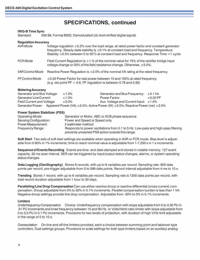
IRIG-B Time SyncStandard: 200-98, Format B002, Demodulated (dc level-shifted digital signal)
Regulation AccuracyAVR Mode Voltage regulation ±0.2% over the load range, at rated power factor and constant generator
frequency. Steady state stability is ±0.1% at constant load and frequency. TemperatureStability ±0.5% between 0 to 50°C at constant load and frequency. Response Time <1 cycle.
FCR Mode Field Current Regulation is ±1.% of the nominal value for 10% of the rectifier bridge inputvoltage change or 20% of the field resistance change. Otherwise, ±5.0%.
VAR Control Mode Reactive Power Regulation is ±2.0% of the nominal VA rating at the rated frequency.
PF Control Mode ±0.02 Power Factor for real power between 10 and 100% at rated frequency.(e.g. set point PF = 0.8, PF regulation is between 0.78 and 0.82)
Metering AccuracyGenerator and Bus Voltage: ±1.0% Generator and Bus Frequency: ±0.1 HzGenerator Line Current: ±1.0% Power Factor: ±0.02 PFField Current and Voltage: ±2.0% Aux. Voltage and Current Input: ±1.0%Generator Power: Apparent Power (VA) ±2.0%; Active Power (W) ±2.0%; Reactive Power (var) ±2.0%
Power System Stabilizer (PSS)Operating Mode: Generator or Motor, ABC or ACB phase sequenceSensing Configuration: Power and Speed or Speed onlyPower Measurement: 2 wattmeter methodFrequency Range: Responds to power oscillations from 0.1 to 5 Hz. Low-pass and high-pass filtering
prevents unwanted PSS action outside this range.
Soft Start Two sets of soft start settings are available when operating in AVR or FCR mode. Bias level is adjust-able from 0-90% in 1% increments; time to reach nominal value is adjustable from 1-7,200 s in 1 s increments.
Sequence of Events Recording Events are time- and date-stamped and stored in volatile memory. 127 eventcapacity, 50 ms scan interval. SER can be triggered by input/output status changes, alarms, or system operatingstatus changes.
Data Logging (Oscillography) Stores 6 records, with up to 6 variables per record. Sampling rate: 600 datapoints per record, pre-trigger adjustable from 0 to 599 data points. Record interval adjustable from 4 ms to 10 s.
Trending Stores 1 record, with up to 6 variables per record. Sampling rate is 1200 data points per record, withtotal record duration adjustable from 1 hour to 30 days.
Paralleling/Line Drop Compensation Can use either reactive droop or reactive differential (cross-current) com-pensation. Droop adjustable from 0% to 30% in 0.1% increments. Parallel compensation burden is less than 1 VA.Negative droop settings provide line drop compensation. Adjustable from -30% to 0% in 0.1% increments.
LimitersUnderfrequency Compensation Choice: Underfrequency compensation with slope adjustable from 0 to 3.00 PU in.01 PU increments and knee frequency between 15 and 90 Hz, or Volts/Hertz ratio limiter with slope adjustable from0 to 3.0 PU in 0.1 PU increments. Provisions for two levels of protection, with duration of high V/Hz limit adjustablein the range of 0 to 10 s.
Overexcitation On-line and off-line limiters provided, each a choice between summing point and takeover typecontrollers. Dual settings groups. Provisions to scale settings for both type limiters based on an auxiliary analog
DECS-400 Digital Excitation Control System
5
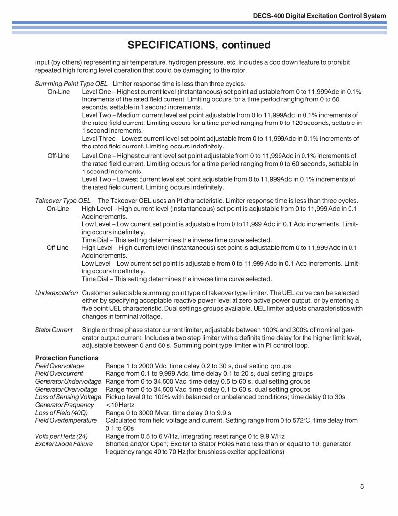
Off-Line Level One – Highest current level set point adjustable from 0 to 11,999Adc in 0.1% increments ofthe rated field current. Limiting occurs for a time period ranging from 0 to 60 seconds, settable in1 second increments.Level Two – Lowest current level set point adjustable from 0 to 11,999Adc in 0.1% increments ofthe rated field current. Limiting occurs indefinitely.
Takeover Type OEL The Takeover OEL uses an I2t characteristic. Limiter response time is less than three cycles.On-Line High Level – High current level (instantaneous) set point is adjustable from 0 to 11,999 Adc in 0.1
Adc increments.Low Level – Low current set point is adjustable from 0 to11,999 Adc in 0.1 Adc increments. Limit-ing occurs indefinitely.Time Dial – This setting determines the inverse time curve selected.
Off-Line High Level – High current level (instantaneous) set point is adjustable from 0 to 11,999 Adc in 0.1Adc increments.Low Level – Low current set point is adjustable from 0 to 11,999 Adc in 0.1 Adc increments. Limit-ing occurs indefinitely.Time Dial – This setting determines the inverse time curve selected.
Underexcitation Customer selectable summing point type of takeover type limiter. The UEL curve can be selectedeither by specifying acceptable reactive power level at zero active power output, or by entering afive point UEL characteristic. Dual settings groups available. UEL limiter adjusts characteristics withchanges in terminal voltage.
Stator Current Single or three phase stator current limiter, adjustable between 100% and 300% of nominal gen-erator output current. Includes a two-step limiter with a definite time delay for the higher limit level,adjustable between 0 and 60 s. Summing point type limiter with PI control loop.
Protection FunctionsField Overvoltage Range 1 to 2000 Vdc, time delay 0.2 to 30 s, dual setting groupsField Overcurrent Range from 0.1 to 9,999 Adc, time delay 0.1 to 20 s, dual setting groupsGenerator Undervoltage Range from 0 to 34,500 Vac, time delay 0.5 to 60 s, dual setting groupsGenerator Overvoltage Range from 0 to 34,500 Vac, time delay 0.1 to 60 s, dual setting groupsLoss of Sensing Voltage Pickup level 0 to 100% with balanced or unbalanced conditions; time delay 0 to 30sGenerator Frequency <10 HertzLoss of Field (40Q) Range 0 to 3000 Mvar, time delay 0 to 9.9 sField Overtemperature Calculated from field voltage and current. Setting range from 0 to 572°C, time delay from
0.1 to 60sVolts per Hertz (24) Range from 0.5 to 6 V/Hz, integrating reset range 0 to 9.9 V/HzExciter Diode Failure Shorted and/or Open; Exciter to Stator Poles Ratio less than or equal to 10, generator
frequency range 40 to 70 Hz (for brushless exciter applications)
SPECIFICATIONS, continued
input (by others) representing air temperature, hydrogen pressure, etc. Includes a cooldown feature to prohibitrepeated high forcing level operation that could be damaging to the rotor.
Summing Point Type OEL Limiter response time is less than three cycles.On-Line Level One – Highest current level (instantaneous) set point adjustable from 0 to 11,999Adc in 0.1%
increments of the rated field current. Limiting occurs for a time period ranging from 0 to 60seconds, settable in 1 second increments.Level Two – Medium current level set point adjustable from 0 to 11,999Adc in 0.1% increments ofthe rated field current. Limiting occurs for a time period ranging from 0 to 120 seconds, settable in1 second increments.Level Three – Lowest current level set point adjustable from 0 to 11,999Adc in 0.1% increments ofthe rated field current. Limiting occurs indefinitely.
DECS-400 Digital Excitation Control System
6
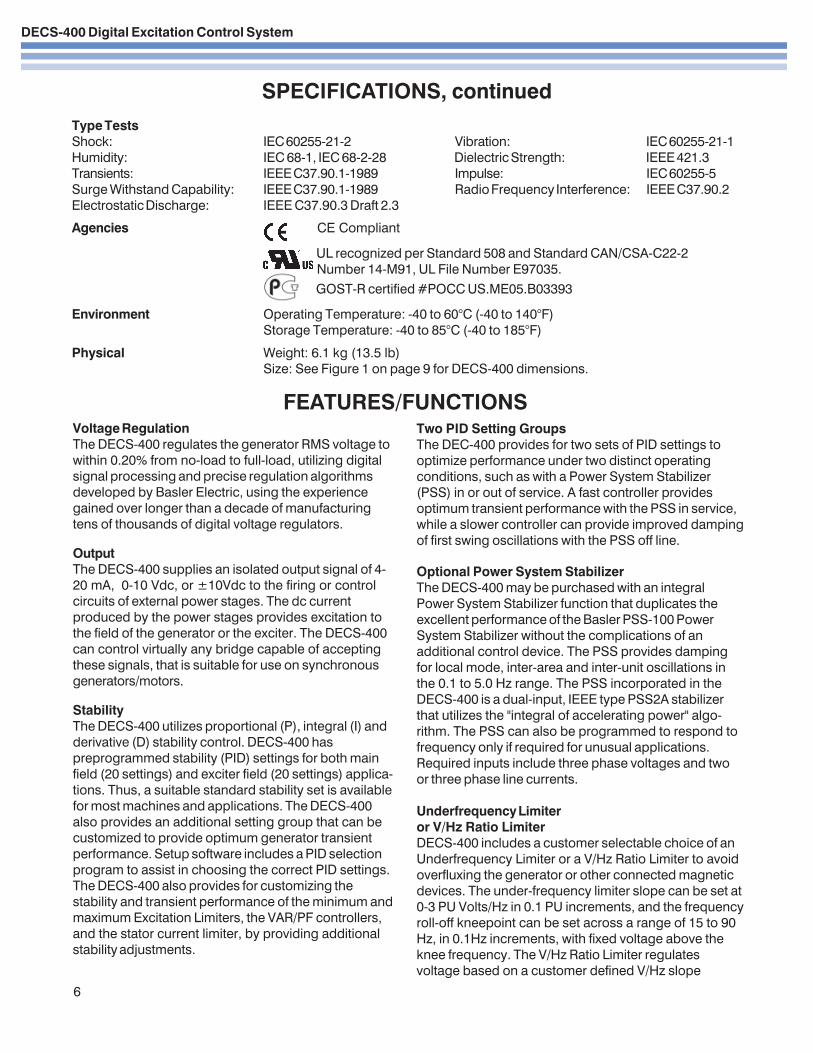
FEATURES/FUNCTIONSVoltage RegulationThe DECS-400 regulates the generator RMS voltage towithin 0.20% from no-load to full-load, utilizing digitalsignal processing and precise regulation algorithmsdeveloped by Basler Electric, using the experiencegained over longer than a decade of manufacturingtens of thousands of digital voltage regulators.
OutputThe DECS-400 supplies an isolated output signal of 4-20 mA, 0-10 Vdc, or ±10Vdc to the firing or controlcircuits of external power stages. The dc currentproduced by the power stages provides excitation tothe field of the generator or the exciter. The DECS-400can control virtually any bridge capable of acceptingthese signals, that is suitable for use on synchronousgenerators/motors.
StabilityThe DECS-400 utilizes proportional (P), integral (I) andderivative (D) stability control. DECS-400 haspreprogrammed stability (PID) settings for both mainfield (20 settings) and exciter field (20 settings) applica-tions. Thus, a suitable standard stability set is availablefor most machines and applications. The DECS-400also provides an additional setting group that can becustomized to provide optimum generator transientperformance. Setup software includes a PID selectionprogram to assist in choosing the correct PID settings.The DECS-400 also provides for customizing thestability and transient performance of the minimum andmaximum Excitation Limiters, the VAR/PF controllers,and the stator current limiter, by providing additionalstability adjustments.
Two PID Setting GroupsThe DEC-400 provides for two sets of PID settings tooptimize performance under two distinct operatingconditions, such as with a Power System Stabilizer(PSS) in or out of service. A fast controller providesoptimum transient performance with the PSS in service,while a slower controller can provide improved dampingof first swing oscillations with the PSS off line.
Optional Power System StabilizerThe DECS-400 may be purchased with an integralPower System Stabilizer function that duplicates theexcellent performance of the Basler PSS-100 PowerSystem Stabilizer without the complications of anadditional control device. The PSS provides dampingfor local mode, inter-area and inter-unit oscillations inthe 0.1 to 5.0 Hz range. The PSS incorporated in theDECS-400 is a dual-input, IEEE type PSS2A stabilizerthat utilizes the "integral of accelerating power" algo-rithm. The PSS can also be programmed to respond tofrequency only if required for unusual applications.Required inputs include three phase voltages and twoor three phase line currents.
Underfrequency Limiteror V/Hz Ratio LimiterDECS-400 includes a customer selectable choice of anUnderfrequency Limiter or a V/Hz Ratio Limiter to avoidoverfluxing the generator or other connected magneticdevices. The under-frequency limiter slope can be set at0-3 PU Volts/Hz in 0.1 PU increments, and the frequencyroll-off kneepoint can be set across a range of 15 to 90Hz, in 0.1Hz increments, with fixed voltage above theknee frequency. The V/Hz Ratio Limiter regulatesvoltage based on a customer defined V/Hz slope
SPECIFICATIONS, continuedType TestsShock: IEC 60255-21-2 Vibration: IEC 60255-21-1Humidity: IEC 68-1, IEC 68-2-28 Dielectric Strength: IEEE 421.3Transients: IEEE C37.90.1-1989 Impulse: IEC 60255-5Surge Withstand Capability: IEEE C37.90.1-1989 Radio Frequency Interference: IEEE C37.90.2Electrostatic Discharge: IEEE C37.90.3 Draft 2.3
Agencies CE Compliant
UL recognized per Standard 508 and Standard CAN/CSA-C22-2 Number 14-M91, UL File Number E97035. GOST-R certified #POCC US.ME05.B03393
Environment Operating Temperature: -40 to 60°C (-40 to 140°F)Storage Temperature: -40 to 85°C (-40 to 185°F)
Physical Weight: 6.1 kg (13.5 lb)Size: See Figure 1 on page 9 for DECS-400 dimensions.
DECS-400 Digital Excitation Control System
FEATURES/FUNCTIONS, continued
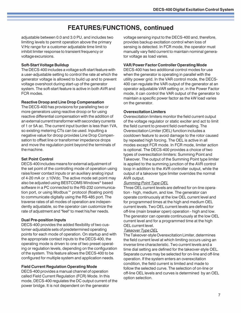
Overexcitation LimitersOverexcitation limiters monitor the field current outputof the voltage regulator or static exciter and act to limitthe field current to prevent field overheating. TheOverexcitation Limiter (OEL) function includes acooldown feature to avoid damage to the rotor causedby repeated high forcing. The OEL is active in allmodes except FCR mode. In FCR mode, limiter actionis optional. The DECS-400 provides a choice of twotypes of overexcitation limiters: Summing Point andTakeover. The output of the Summing Point type limiteris applied to the summing junction of the AVR controlloop in addition to the AVR controller output, while theoutput of a takeover type limiter overrides the normalAVR output.Summing Point Type OELThree OEL current levels are defined for on-line opera-tion - high, medium, and low. The generator canoperate continuously at the low OEL current level andfor programmed times at the high and medium OELcurrent levels. Two OEL current levels are defined foroff-line (main breaker open) operation - high and low.The generator can operate continuously at the low OELcurrent level and for a programmed time at the highOEL current level.Takeover Type OELThe Takeover-style Overexcitation Limiter, determinesthe field current level at which limiting occurs using aninverse time characteristic. Two current levels and atime dial setting are defined for the takeover-style OEL.Separate curves may be selected for on-line and off-lineoperation. If the system enters an overexcitationcondition, the field current is limited and made tofollow the selected curve. The selection of on-line oroff-line OEL levels and curves is determined by an OELoption selection.
7
adjustable between 0.0 and 3.0 PU, and includes twolimiting levels to permit operation above the primaryV/Hz range for a customer adjustable time limit toinhibit limiter response to transient frequency orvoltage excursions.
Soft-Start Voltage BuildupThe DECS-400 includes a voltage soft-start feature witha user-adjustable setting to control the rate at which thegenerator voltage is allowed to build up and to preventvoltage overshoot during start-up of the generatorsystem. The soft-start feature is active in both AVR andFCR modes.
Reactive Droop and Line Drop CompensationThe DECS-400 has provisions for paralleling two ormore generators using reactive droop or for usingreactive differential compensation with the addition ofan external current transformer with secondary currentsof 1 or 5A ac. The current input burden is less than 1VA,so existing metering CTs can be used. Inputting anegative value for droop provides Line Drop Compen-sation to offset line or transformer impedance dropsand move the regulation point beyond the terminals ofthe machine.
Set Point ControlDECS-400 includes means for external adjustment ofthe set point of the controlling mode of operation usingraise/lower contact inputs or an auxiliary analog inputof 4-20 mA or ±10Vdc. The active mode set point mayalso be adjusted using BESTCOMS Windows® basedsoftware in a PC connected to the RS-232 communica-tion port, or using Modbus™ protocol (floating point)to communicate digitally using the RS-485 port. Thetraverse rates of all modes of operation are indepen-dently adjustable, so the operator can customize therate of adjustment and "feel" to meet his/her needs.
Dual Pre-position InputsDECS-400 provides the added flexibility of two cus-tomer-adjustable sets of predetermined operatingpoints for each mode of operation. On startup and withthe appropriate contact inputs to the DECS-400, theoperating mode is driven to one of two preset operat-ing or regulation levels, depending on the configurationof the system. This feature allows the DECS-400 to beconfigured for multiple system and application needs.
Field Current Regulation Operating ModeDECS-400 provides a manual channel of operationcalled Field Current Regulation (FCR) Mode. In thismode, DECS-400 regulates the DC output current of thepower bridge. It is not dependent on the generator
voltage sensing input to the DECS-400 and, therefore,provides backup excitation control when loss ofsensing is detected. In FCR mode, the operator mustmanually vary field current to maintain nominal genera-tor voltage as load varies.
VAR/Power Factor Controller Operating ModeDECS-400 has two additional control modes for usewhen the generator is operating in parallel with theutility power grid. In the VAR control mode, the DECS-400 can regulate the VAR output of the generator at anoperator adjustable VAR setting or, in the Power Factormode, it can control the VAR output of the generator tomaintain a specific power factor as the kW load varieson the generator.
DECS-400 Digital Excitation Control System
FEATURES/FUNCTIONS, continued
8
Stator Current LimiterThe stator current limiter (SCL) senses the level of statorcurrent and limits it to prevent stator overheating. TheSCL operates in all modes except FCR. In FCR mode,the DECS-400 provides indication that a statorovercurrent condition exists, but limiter action is inhib-ited. Two SCL current levels are provided: high and low.The generator can operate continuously at the low SCLlevel, but only for a programmed time at the high SCLlevel.
Autotracking Between DECS-400 Operating ModesDECS-400 is an intelligent device that can provideautotracking (autofollowing) of the controlling mode bythe non-controlling modes. This allows the operator toinitiate a controlled, bumpless transfer of the DECS-400between operating modes with minimal disturbance tothe power system. This feature can be used in conjunc-tion with a set of protective relays to initiate a transfer toa backup mode of operation, such as FCR mode, uponthe detection of a system failure or fault, such as loss ofsensing.
Autotracking between DECS-400 UnitsThe DECS-400 is also designed to automatically track asecond DECS-400 unit using dedicated communicationports on the two units. A backup DECS-400 controllercan be placed in service and programmed to track thecontrol output of the primary DECS-400. In the unlikelyevent of a failure of the first DECS-400, protective relayscan initiate a transfer of control from the first to thesecond DECS-400 with minimal system disturbance.
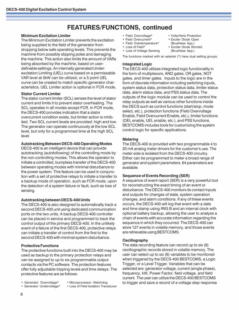
Protective FunctionsThe protective functions built into the DECS-400 may beused as backup to the primary protection relays andcan be assigned to up to six programmable outputcontacts via the PC software. The protection featuresoffer fully adjustable tripping levels and time delays. Theprotective features are as follows:
• Generator Overvoltage* • Microprocessor Watchdog• Generator Undervoltage* • Loss of Field Isolation Transducer
• Field Overvoltage* • Volts/Hertz Protection• Field Overcurrent* • Exciter Diode Open• Field Overtemperature* (Brushless App.)• Loss of Field* • Exciter Diode Shorted• Loss of Voltage Sensing (Brushless App.)
The functions marked with an asterisk (*) have dual setting groups.
Integrated LogicThe DECS-400 utilizes integrated logic functionality inthe form of multiplexors, AND gates, OR gates, NOTgates, and timer gates. Inputs to the logic are in theform of discrete information including switching inputs,system status data, protection status data, limiter statusdata, alarm status data, and PSS status data. Theoutputs of the logic module can be used to control therelay outputs as well as various other functions insidethe DECS such as control functions (start/stop, modeselect, etc.), protection functions (Field OvervoltageEnable, Field Overcurrent Enable, etc.), limiter functions(OEL enable, UEL enable, etc.), and PSS functions.BESTCOMS includes tools for customizing the systemcontrol logic for specific applications.
MeteringThe DECS-400 is provided with two programmable 4 to20 mA analog meter drivers for the customer's use. Themeter side is isolated from the DECS-400 circuitry.Either can be programmed to meter a broad range ofgenerator and system parameters. 64 parameters areavailable.
Sequence of Events Recording (SER)A sequence of event report (SER) is a very powerful toolfor reconstructing the exact timing of an event ordisturbance. The DECS-400 monitors its contact inputsand outputs for changes of state, system operationchanges, and alarm conditions. If any of these eventsoccurs, the DECS-400 will log that event with a dateand time stamp using IRIG B and an internal clock withoptional battery backup, allowing the user to analyze achain of events with accurate information regarding thesequence in which they occurred. The DECS-400 canstore 127 events in volatile memory, and those eventsare retrievable using BESTCOMS.
OscillographyThe data recording feature can record up to six (6)oscillographic records stored in volatile memory. Theuser can select up to six (6) variables to be monitoredwhen triggered by the DECS-400 BESTCOMS, a LogicTrigger, or a Level Trigger. Variables that can beselected are: generator voltage, current (single phase),frequency, kW, Power Factor, field voltage, and fieldcurrent. The user can utilize the DECS-400 BESTCOMSto trigger and save a record of a voltage step response
Minimum Excitation LimiterThe Minimum Excitation Limiter prevents the excitationbeing supplied to the field of the generator fromdropping below safe operating levels. This prevents themachine from possibly slipping poles and damagingthe machine. This action also limits the amount of VARsbeing absorbed by the machine, based on user-definable settings. An internally generated Under-excitation Limiting (UEL) curve based on a permissableVAR level at 0kW can be utilized, or a 5 point UELcurve can be created to match specific generator char-acteristics. UEL Limiter action is optional in FCR mode.
DECS-400 Digital Excitation Control System
9
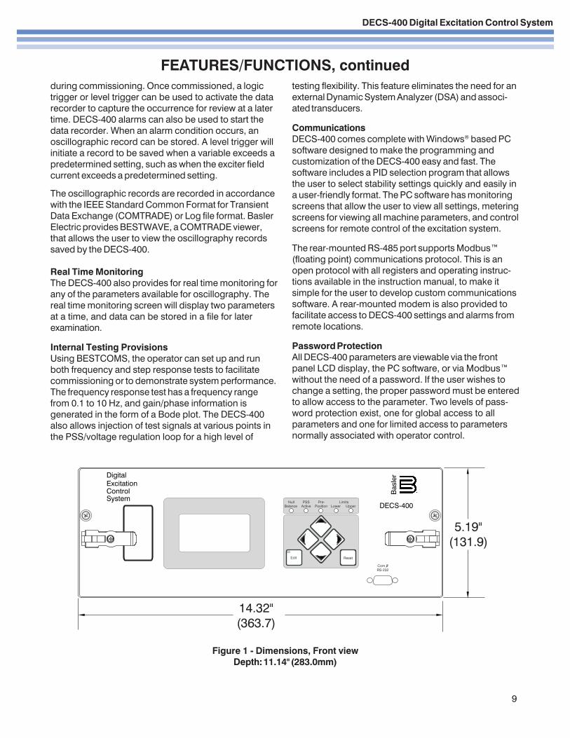
Figure 1 - Dimensions, Front viewDepth: 11.14" (283.0mm)
during commissioning. Once commissioned, a logictrigger or level trigger can be used to activate the datarecorder to capture the occurrence for review at a latertime. DECS-400 alarms can also be used to start thedata recorder. When an alarm condition occurs, anoscillographic record can be stored. A level trigger willinitiate a record to be saved when a variable exceeds apredetermined setting, such as when the exciter fieldcurrent exceeds a predetermined setting.
The oscillographic records are recorded in accordancewith the IEEE Standard Common Format for TransientData Exchange (COMTRADE) or Log file format. BaslerElectric provides BESTWAVE, a COMTRADE viewer,that allows the user to view the oscillography recordssaved by the DECS-400.
Real Time MonitoringThe DECS-400 also provides for real time monitoring forany of the parameters available for oscillography. Thereal time monitoring screen will display two parametersat a time, and data can be stored in a file for laterexamination.
Internal Testing ProvisionsUsing BESTCOMS, the operator can set up and runboth frequency and step response tests to facilitatecommissioning or to demonstrate system performance.The frequency response test has a frequency rangefrom 0.1 to 10 Hz, and gain/phase information isgenerated in the form of a Bode plot. The DECS-400also allows injection of test signals at various points inthe PSS/voltage regulation loop for a high level of
testing flexibility. This feature eliminates the need for anexternal Dynamic System Analyzer (DSA) and associ-ated transducers.
CommunicationsDECS-400 comes complete with Windows® based PCsoftware designed to make the programming andcustomization of the DECS-400 easy and fast. Thesoftware includes a PID selection program that allowsthe user to select stability settings quickly and easily ina user-friendly format. The PC software has monitoringscreens that allow the user to view all settings, meteringscreens for viewing all machine parameters, and controlscreens for remote control of the excitation system.
The rear-mounted RS-485 port supports Modbus™(floating point) communications protocol. This is anopen protocol with all registers and operating instruc-tions available in the instruction manual, to make itsimple for the user to develop custom communicationssoftware. A rear-mounted modem is also provided tofacilitate access to DECS-400 settings and alarms fromremote locations.
Password ProtectionAll DECS-400 parameters are viewable via the frontpanel LCD display, the PC software, or via Modbus™without the need of a password. If the user wishes tochange a setting, the proper password must be enteredto allow access to the parameter. Two levels of pass-word protection exist, one for global access to allparameters and one for limited access to parametersnormally associated with operator control.
FEATURES/FUNCTIONS, continued
DECS-400 Digital Excitation Control System
10
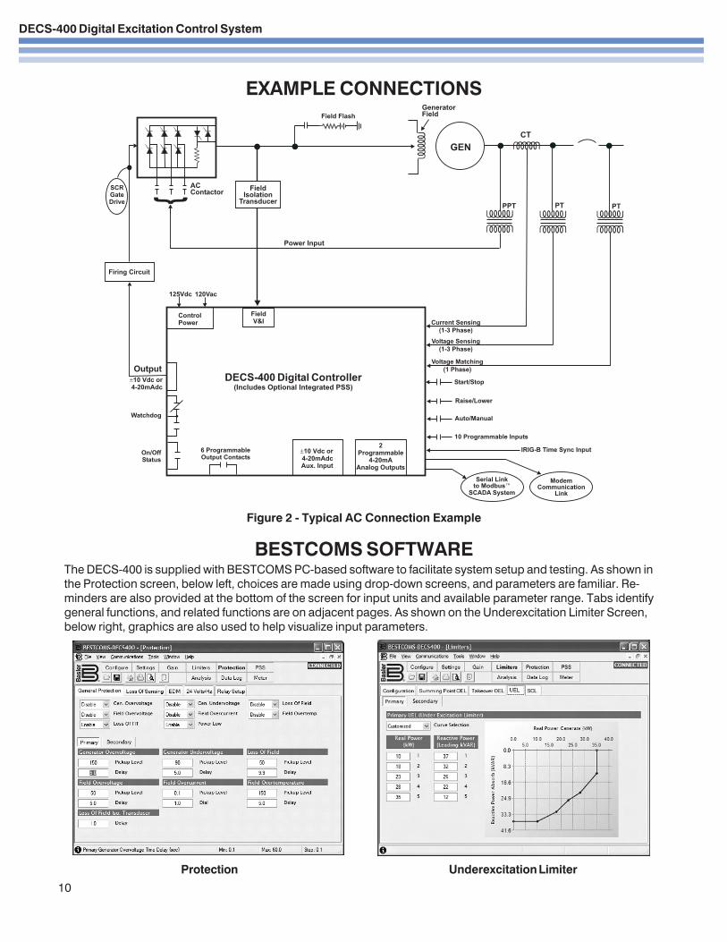
EXAMPLE CONNECTIONS
Figure 2 - Typical AC Connection Example
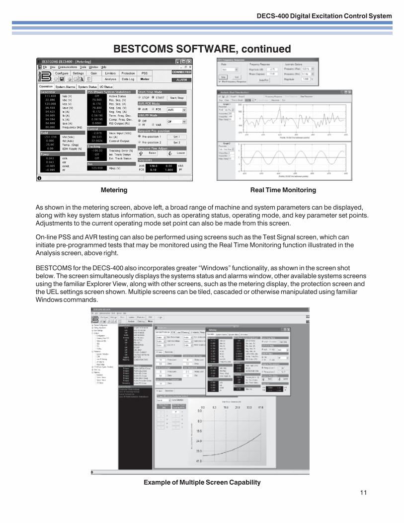
BESTCOMS SOFTWARE
Protection Underexcitation Limiter
The DECS-400 is supplied with BESTCOMS PC-based software to facilitate system setup and testing. As shown inthe Protection screen, below left, choices are made using drop-down screens, and parameters are familiar. Re-minders are also provided at the bottom of the screen for input units and available parameter range. Tabs identifygeneral functions, and related functions are on adjacent pages. As shown on the Underexcitation Limiter Screen,below right, graphics are also used to help visualize input parameters.
DECS-400 Digital Excitation Control System
11
BESTCOMS SOFTWARE, continued
Metering Real Time Monitoring
Example of Multiple Screen Capability
As shown in the metering screen, above left, a broad range of machine and system parameters can be displayed,along with key system status information, such as operating status, operating mode, and key parameter set points.Adjustments to the current operating mode set point can also be made from this screen.
On-line PSS and AVR testing can also be performed using screens such as the Test Signal screen, which caninitiate pre-programmed tests that may be monitored using the Real Time Monitoring function illustrated in theAnalysis screen, above right.
BESTCOMS for the DECS-400 also incorporates greater “Windows” functionality, as shown in the screen shotbelow. The screen simultaneously displays the systems status and alarms window, other available systems screensusing the familiar Explorer View, along with other screens, such as the metering display, the protection screen andthe UEL settings screen shown. Multiple screens can be tiled, cascaded or otherwise manipulated using familiarWindows commands.
DECS-400 Digital Excitation Control System
Printed in U.S.A.
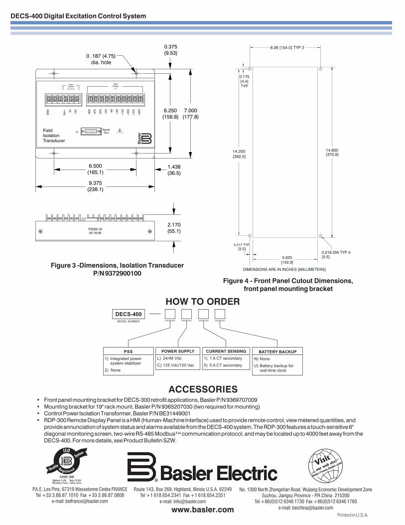
HOW TO ORDER
ACCESSORIES• Front panel mounting bracket for DECS-300 retrofit applications, Basler P/N 9369707009• Mounting bracket for 19" rack mount, Basler P/N 9365207030 (two required for mounting)• Control Power Isolation Transformer, Basler P/N BE31449001• RDP-300 Remote Display Panel is a HMI (Human-Machine Interface) used to provide remote control, view metered quantities, and
provide annunciation of system status and alarms available from the DECS-400 system. The RDP-300 features a touch-sensitive 6"diagonal monitoring screen, two-wire RS-485 Modbus™ communication protocol, and may be located up to 4000 feet away from theDECS-400. For more details, see Product Bulletin SZW.
Route 143, Box 269, Highland, Illinois U.S.A. 62249Tel +1 618.654.2341 Fax +1 618.654.2351
e-mail: [email protected]
No. 1300 North Zhongshan Road, Wujiang Economic Development ZoneSuzhou, Jiangsu Province - P.R.China 215200
Tel +86(0)512 6346 1730 Fax +86(0)512 6346 1760e-mail: [email protected]
P.A.E. Les Pins, 67319 Wasselonne Cedex FRANCETel +33 3.88.87.1010 Fax +33 3.88.87.0808
e-mail: [email protected]
Figure 4 - Front Panel Cutout Dimensions,front panel mounting bracket
Figure 3 -Dimensions, Isolation TransducerP/N 9372900100
14.600[370.8]
5.625
[142.9]
0.217 TYP
[362.0]
[5.5]0.218 DIA TYP 4[5.5]
14.250
DIMENSIONS ARE IN INCHES [MILLIMETERS]
6.06 [154.0] TYP 2
0.175
[4.4]
TYP