Embed Size (px)
Citation preview
INSTRUCTION MANUAL FOR
DIGITAL EXCITATION CONTROL SYSTEM
DECS-100
Publication: 9287500991 Revision: K 05/11

9287500991 Rev K DECS-100 Introduction i
INTRODUCTION This instruction manual provides information about the operation and installation of the DECS-100 Digital Excitation Control System. To accomplish this, the following information is provided:
General Information and Specifications Controls and Indicators Functio nal Description Ins tallation Maintenance and Troubleshooting
WARNING! To avoid person al injury o r equipment damage, only qualified person nel should perform the procedures in this manual. Lethal voltage is present at the rear panel when the unit is energized. Rear panel connections should be made only when the unit id de-energized.
NOTE Be sure that the DECS-100 is hard-wired to earth ground with no smaller than 12 AWG copper wire atta ched to the grou nd terminal on the rea r of the unit ca se. When the DECS-10 0 is configu red in a system with other device s, it is recommended to use a separate lead to the ground bus from each unit.
CAUTION The Man ual mode excit ation level must be eva luated pri or to enabling t his feature. If the level of excitation cu rrent is inappropriate for the generator, severe damage to the generator may occur. Improper PID numbers will result in poor system performance or system damage. When ap plying ope rating power for programming purposes, o bserve th e pre-cautions called out in Section 4, Installation, Preliminary Setup. When p rogramming th e DECS -100 wit hout th e gen erator spin ning, t he connections to DECS-100 terminals F+ and F– should be removed. Before uploading a settings file, remove ope rating power f rom t he DECS-100, disconnect the field wirin g from termin als F+ a nd F–, and re -apply operatin g power to the DECS-100.
ii DECS-100 Introduction 9287500991 Rev K
First Printing: March 2001
Printed in USA
© 2011 Basler Electric, Highland Illinois 62249 USA
All Rights Reserved
May 2011
It is not the intention of this manual to cover all details and variations in equipment, nor does this manual provide data for every possible contingency regarding installation or operation. The availability and design of all feature s and o ptions are su bject to modifica tion without notice. Shoul d further info rmation b e required, contact Basler Electric.
BASLER ELECTRIC 12570 STATE ROUTE 143 HIGHLAND IL 62249 USA
http://www.basler.com, [email protected] PHONE +1 618.654.2341 FAX +1 618.654.2351
CONFIDENTIAL INFORMATION of Basler Electric, Highland Illinois, USA. It is loaned for confidential use, subject to return on request, and with the mutual understanding that it will not be used in any manner detrimental to the interest of Basler Electric.
9287500991 Rev K DECS-100 Introduction iii
REVISION HISTORY
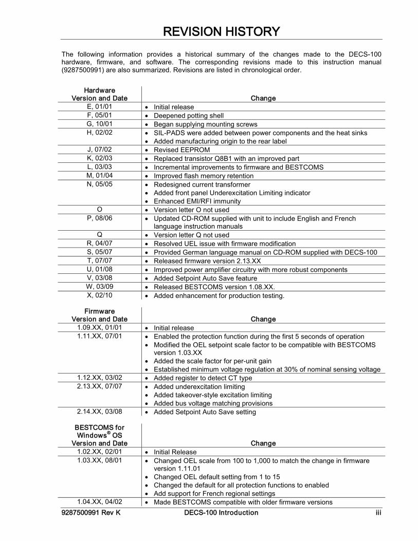
The following information provides a historical summary of the changes made to the DECS-100 hardware, firmware, and software. The corresponding revisions made to this instruction manual (9287500991) are also summarized. Revisions are listed in chronological order.
Hardware Version and Date Change
E, 01/01 • Initial release F, 05/01 • Deepened potting shell G, 10/01 • Began supplying mounting screws H, 02/02 • SIL-PADS were added between power components and the heat sinks
• Added manufacturing origin to the rear label J, 07/02 • Revised EEPROM K, 02/03 • Replaced transistor Q8B1 with an improved part L, 03/03 • Incremental improvements to firmware and BESTCOMS M, 01/04 • Improved flash memory retention N, 05/05 • Redesigned current transformer
• Added front panel Underexcitation Limiting indicator • Enhanced EMI/RFI immunity
O • Version letter O not used P, 08/06 • Updated CD-ROM supplied with unit to include English and French
language instruction manuals Q • Version letter Q not used
R, 04/07 • Resolved UEL issue with firmware modification S, 05/07 • Provided German language manual on CD-ROM supplied with DECS-100 T, 07/07 • Released firmware version 2.13.XX U, 01/08 • Improved power amplifier circuitry with more robust components V, 03/08 • Added Setpoint Auto Save feature W, 03/09 • Released BESTCOMS version 1.08.XX. X, 02/10 • Added enhancement for production testing.
Firmware
Version and Date Change 1.09.XX, 01/01 • Initial release 1.11.XX, 07/01 • Enabled the protection function during the first 5 seconds of operation
• Modified the OEL setpoint scale factor to be compatible with BESTCOMS version 1.03.XX
• Added the scale factor for per-unit gain • Established minimum voltage regulation at 30% of nominal sensing voltage
1.12.XX, 03/02 • Added register to detect CT type 2.13.XX, 07/07 • Added underexcitation limiting
• Added takeover-style excitation limiting • Added bus voltage matching provisions
2.14.XX, 03/08 • Added Setpoint Auto Save setting
BESTCOMS for Windows® OS
Version and Date Change 1.02.XX, 02/01 • Initial Release 1.03.XX, 08/01 • Changed OEL scale from 100 to 1,000 to match the change in firmware
version 1.11.01 • Changed OEL default setting from 1 to 15 • Changed the default for all protection functions to enabled • Add support for French regional settings
1.04.XX, 04/02 • Made BESTCOMS compatible with older firmware versions
iv DECS-100 Introduction 9287500991 Rev K
BESTCOMS for Windows® OS
Version and Date Change • Added support for all regional settings • Enabled reading of secondary CT value for units with firmware version
1.12.01 and higher • Simplified the Analysis screen • Added feature to calculate and send voltage matching reference for
different generator and bus PT ratios • Changed minimum Ki setpoint from 0 to 0.01
1.05.XX, 05/05 • Added underexcitation limiting capability • Added ability to select either summing point or takeover style OEL • Added provisions for bus voltage matching
1.06.XX, 11/07 • Added compatibility with Microsoft® Vista to BESTCOMS 1.07.XX, 03/08 • Added Setpoint Auto Save setting. 1.08.XX, 03/09 • Improved communications with DECS-100. 1.09.XX, 01/11 • Added Windows® 7 compatibility and improved field overvoltage
shutdown.
BESTCOMS for Palm® OS
Version and Date Change 1.01.XX, 01/01 • Initial Release 1.02.XX, 08/01 • Added a Check for New Version button to the Contact Basler screen
• Added a date/time stamp to the “Save to File” names • Added version checking
1.03.XX, 04/02 • Added password protection • Improved version checking function
NOTE • BESTCOMS for Palm OS is compatible only with firmware versions 1.12.XX and earlier
Manual
Revision and Date Change —, 03/01 • Initial release A, 03/01 • In Section 5, BESTCOMS Software for the Windows® Operating System
and Section 6, BESTCOMS Software for the Palm OS® Platform, Step 2 of Installing BESTCOMS was revised to reflect the addition of an auto-start utility for the DECS-100 CD-ROM
B, 08/01 • Added Embedded Software subsection to Section 5, BESTCOMS Software for the Windows® Operating System
• Corrected various minor errors throughout manual C, 05/02 • Revised the torque specification for the mounting screws supplied with unit
• In Section 5, BESTCOMS Software for the Windows® Operating System and Section 6, BESTCOMS Software for the Palm® OS Platform, text and illustrations were revised to accommodate software enhancements
D, 01/03 • Revised Voltage Matching Time Adjustment Range from 0 to 300 seconds to 1 to 300 seconds throughout manual
• Corrected figure number references in Sections 5 and 6 E, 03/04 • Added Operating Power Considerations During DECS-100 Programming to
Section 4, Installation, Preliminary Setup • Added caution box regarding application of operating power during DECS-
100 programming to Section 5, BESTCOMS for Windows® OS and Section 6, BESTCOMS for Palm OS®
• Corrected CT ratio setting range stated in Section 5
9287500991 Rev K DECS-100 Introduction v
Manual Revision and Date Change
F, 05/05 • Added material covering added UEL capability • Revised all drawings to show new front panel with UEL indicator • Updated all illustrations of rear panel to show revised CT • Added discussion of summing point and takeover style OEL limiting • Revised voltage matching description to cover Maintain and Revert modes • Corrected the hole drilling diameter shown in Figure 4-2 • Added illustration/description for using the ICRM-7 with the DECS-100 • Removed Section 6, BESTCOMS Software for the Palm® OS Platform and
moved Maintenance and Troubleshooting to Section 6 • Added troubleshooting procedure for a UEL annunciation
G, 03/07 • Corrected illustration and descriptions of BESTCOMS Metering, Operation and Alarms screen, Operation tab
• Removed expired patent information H, 05/08 • Added DNV compliance statement to manual specifications
• Added description of BESTCOMS Setpoint Auto Save feature J, 10/08 • Revised the setting ranges of control gain settings OEL KI, OEL Kg,
UEL KI, and UEL Kg from 0–1,000 to 0–300 to reflect changes made in BESTCOMS version 1.07.01.
K, 05/11 • Revised Introduction to reflect new epoxy-potted package. • Removed “(optional feature)” from note 5 of Figures 4-7 to 4-10, due to the
setpoint option now being standard. • Added storage / electrolytic capacitors procedure to Section 6. • Corrected various minor errors throughout manual

vi DECS-100 Introduction 9287500991 Rev K
This page intentionally left blank.
9287500991 Rev K DECS-100 Introduction vii
CONTENTS
A detailed table of contents is provided at the start of each manual section. The manual sections are ordered as follows. Section 1 General Information .................................................................................................. 1-1
Section 2 Human-Machine Interface ......................................................................................... 2-1
Section 3 Functional Description .............................................................................................. 3-1
Section 4 Installation ................................................................................................................. 4-1
Section 5 BESTCOMS Software ............................................................................................... 5-1
Section 6 Maintenance and Troubleshooting............................................................................ 6-1

viii DECS-100 Introduction 9287500991 Rev K
This page intentionally left blank.
9287500991 Rev K DECS-100 General Information i
SECTION 1 • GENERAL INFORMATION
TABLE OF CONTENTS SECTION 1 • GENERAL INFORMATION ................................................................................................ 1-1
INTRODUCTION.................................................................................................................................... 1-1 FEATURES ............................................................................................................................................ 1-1 MODEL AND STYLE NUMBER ............................................................................................................. 1-1
Style Number ...................................................................................................................................... 1-1 SPECIFICATIONS ................................................................................................................................. 1-2
Operating Power ................................................................................................................................ 1-2 Generator Voltage Sensing ................................................................................................................ 1-2 Generator Current Sensing ................................................................................................................ 1-2 Bus Voltage Sensing (Optional) ......................................................................................................... 1-2 Accessory Input .................................................................................................................................. 1-3 Communication Port ........................................................................................................................... 1-3 Contact Input Circuits ......................................................................................................................... 1-3 Common Alarm Output ....................................................................................................................... 1-3 Field Output ........................................................................................................................................ 1-3 AVR Operating Mode ......................................................................................................................... 1-3 FCR (Manual) Operating Mode .......................................................................................................... 1-4 Var Operating Mode (Optional) .......................................................................................................... 1-4 PF Operating Mode (Optional) ........................................................................................................... 1-4 Parallel Compensation ....................................................................................................................... 1-4 Field Overvoltage Protection .............................................................................................................. 1-4 Generator Overvoltage Protection ..................................................................................................... 1-4 Overexcitation Limiter ......................................................................................................................... 1-5 Underexcitation Limiter ....................................................................................................................... 1-5 Soft Start Function (AVR Mode Only) ................................................................................................ 1-5 Voltage Matching ................................................................................................................................ 1-5 Metering (BESTCOMS) ...................................................................................................................... 1-5 Environment ....................................................................................................................................... 1-6 Type Tests .......................................................................................................................................... 1-6 Physical .............................................................................................................................................. 1-6 Agency Recognition ........................................................................................................................... 1-6 CE Compliance .................................................................................................................................. 1-6
Figures Figure 1-1. DECS-100 Style Chart ............................................................................................................ 1-1 Figure 1-2. Typical V/Hz Curves ................................................................................................................ 1-4

ii DECS-100 General Information 9287500991 Rev K
This page intentionally left blank.
9287500991 Rev K DECS-100 General Information 1-1
SECTION 1 • GENERAL INFORMATION INTRODUCTION The Basler Digital Excitation Control System (DECS-100) is an electronic, solid-state, microprocessor based control device. The DECS-100 regulates the output voltage of a brushless, ac generator by controlling the current into the generator exciter field. Input power to the DECS-100 can be from a multi-pole, high-frequency, permanent magnet generator (PMG) or from the generator output when used as a conventional, shunt-excited, excitation system. The DECS-100 is supplied in an epoxy-potted package designed for behind-the-panel mounting. The DECS-100 is held in place by thread-forming screws that thread into its plastic shell. Front panel indicators (LEDs) annunciate DECS-100 status and system conditions. DECS-100 connections are made through quarter-inch, quick-connect terminals on the rear panel. A 9-pin DB-9 type connector on the rear panel provides communication between the DECS-100 and an IBM compatible PC.
FEATURES DECS-100 units have the following features and capabilities: • Four control modes: automatic voltage regulation (AVR), manual or field current regulation (FCR),
power factor (PF) regulation, and reactive power (var) regulation. • Programmable stability settings. • Soft start and voltage buildup control with an adjustable ramp in AVR control mode. • Overexcitation limiting (OEL) and underexcitation limiting (UEL) in AVR, Var, and PF control modes. • Underfrequency (volts/hertz) regulation. • Three-phase or single-phase generator voltage (rms) sensing/regulation in AVR mode. • Single-phase bus voltage (rms) sensing. • Single-phase generator current sensing for metering and regulation purposes. • Field current and field voltage sensing. • One analog input for proportional remote control of the setpoint. • Five contact sensing inputs for system interface. • One common output relay for alarm indication and trip functions. • Three protection functions: field overvoltage, generator overvoltage, and loss of sensing. • Generator paralleling with reactive droop compensation and reactive differential compensation. • Rear RS-232 communication port for personal computer communication using BESTCOMS
Windows® based software for fast, user-friendly, setup and control.
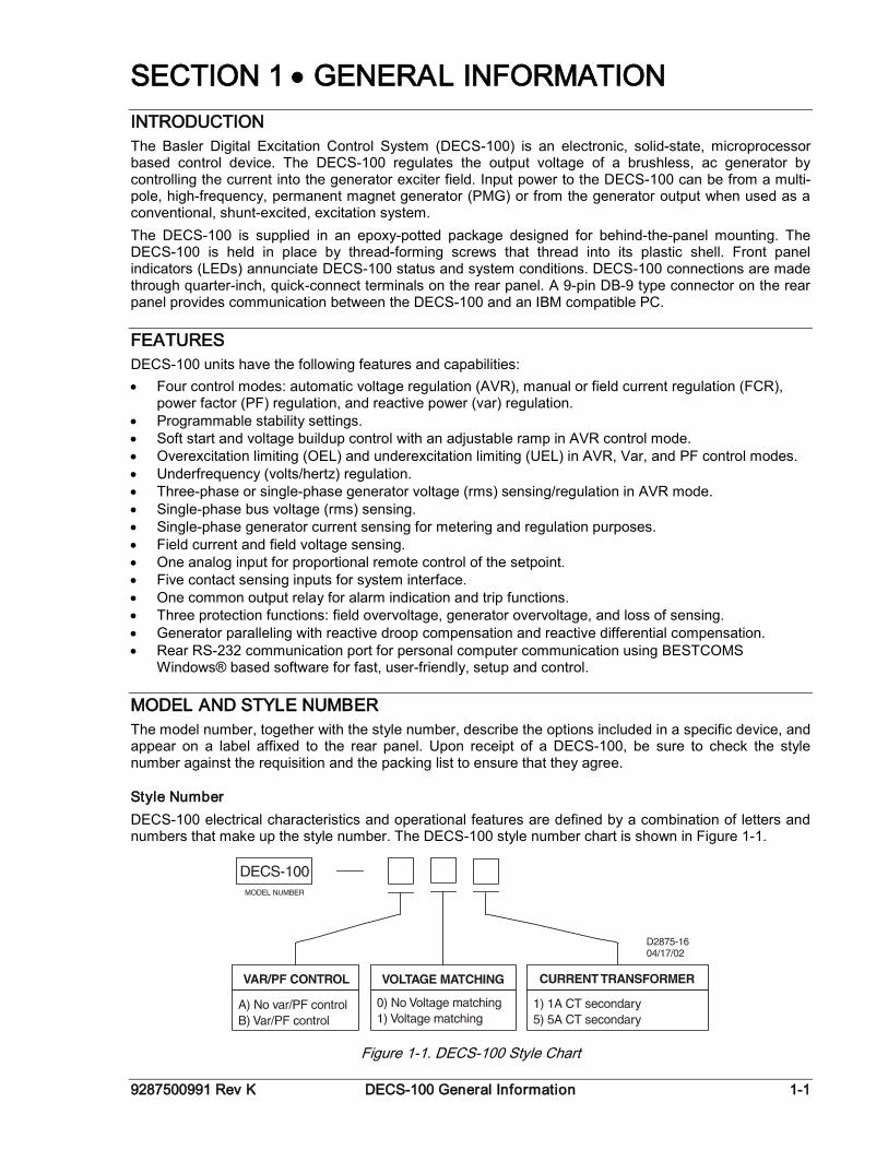
MODEL AND STYLE NUMBER The model number, together with the style number, describe the options included in a specific device, and appear on a label affixed to the rear panel. Upon receipt of a DECS-100, be sure to check the style number against the requisition and the packing list to ensure that they agree.
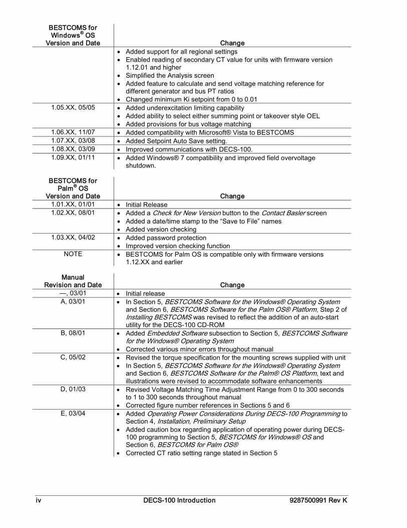
Style Number DECS-100 electrical characteristics and operational features are defined by a combination of letters and numbers that make up the style number. The DECS-100 style number chart is shown in Figure 1-1.
Figure 1-1. DECS-100 Style Chart
1-2 DECS-100 General Information 9287500991 Rev K
For example, a DECS-100 with a style number of A15 would have the following characteristics and operating features.
Style Number Example
A ------- No var or power factor control 1 -------- Voltage matching 5 -------- 5 ampere current sensing
SPECIFICATIONS DECS-100 specifications and qualifications are listed in the following paragraphs.
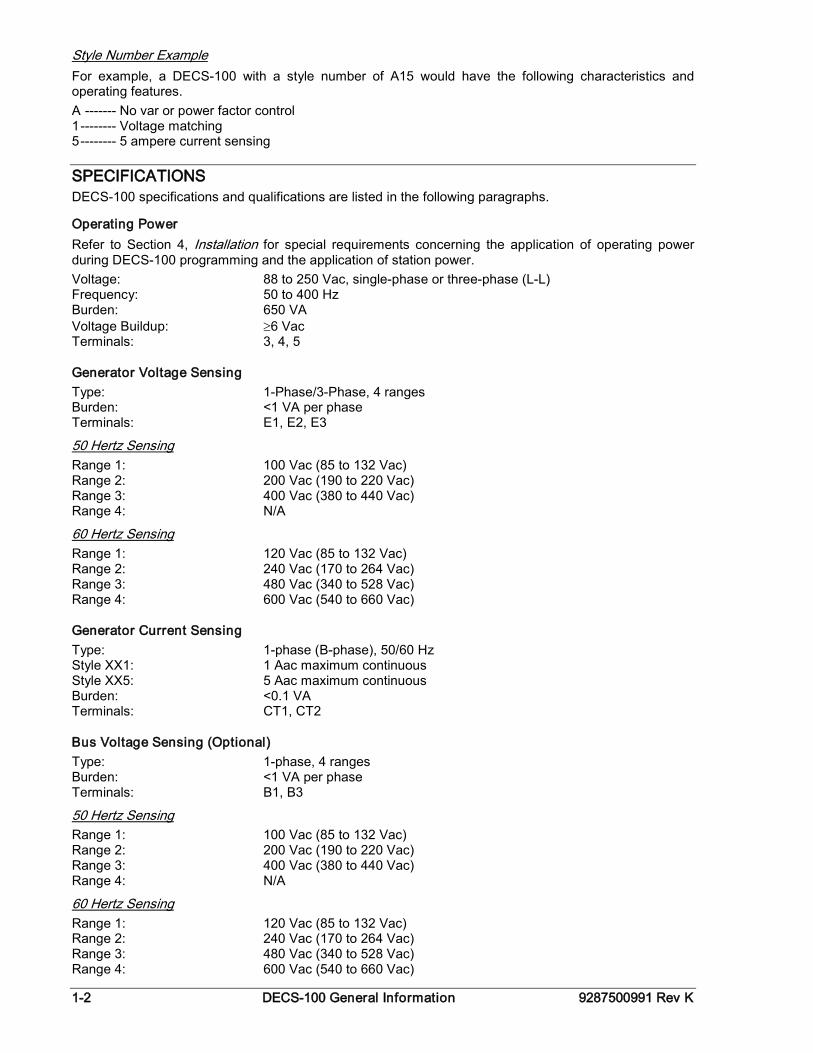
Operating Power Refer to Section 4, Installation for special requirements concerning the application of operating power during DECS-100 programming and the application of station power. Voltage: 88 to 250 Vac, single-phase or three-phase (L-L) Frequency: 50 to 400 Hz Burden: 650 VA Voltage Buildup: ≥6 Vac Terminals: 3, 4, 5
Generator Voltage Sensing Type: 1-Phase/3-Phase, 4 ranges Burden: <1 VA per phase Terminals: E1, E2, E3
Range 1: 100 Vac (85 to 132 Vac) 50 Hertz Sensing
Range 2: 200 Vac (190 to 220 Vac) Range 3: 400 Vac (380 to 440 Vac) Range 4: N/A
Range 1: 120 Vac (85 to 132 Vac) 60 Hertz Sensing
Range 2: 240 Vac (170 to 264 Vac) Range 3: 480 Vac (340 to 528 Vac) Range 4: 600 Vac (540 to 660 Vac)
Generator Current Sensing Type: 1-phase (B-phase), 50/60 Hz Style XX1: 1 Aac maximum continuous Style XX5: 5 Aac maximum continuous Burden: <0.1 VA Terminals: CT1, CT2
Bus Voltage Sensing (Optional) Type: 1-phase, 4 ranges Burden: <1 VA per phase Terminals: B1, B3
Range 1: 100 Vac (85 to 132 Vac) 50 Hertz Sensing
Range 2: 200 Vac (190 to 220 Vac) Range 3: 400 Vac (380 to 440 Vac) Range 4: N/A
Range 1: 120 Vac (85 to 132 Vac) 60 Hertz Sensing
Range 2: 240 Vac (170 to 264 Vac) Range 3: 480 Vac (340 to 528 Vac) Range 4: 600 Vac (540 to 660 Vac)
9287500991 Rev K DECS-100 General Information 1-3
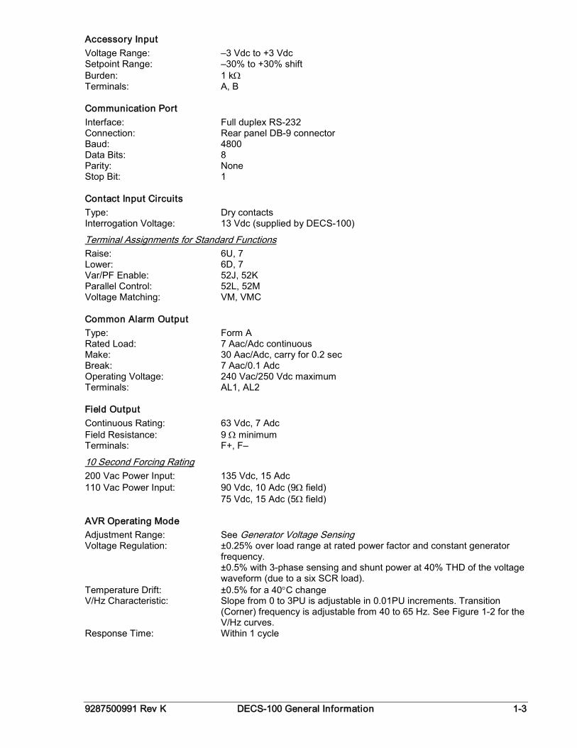
Accessory Input Voltage Range: –3 Vdc to +3 Vdc Setpoint Range: –30% to +30% shift Burden: 1 kΩ Terminals: A, B
Communication Port Interface: Full duplex RS-232 Connection: Rear panel DB-9 connector Baud: 4800 Data Bits: 8 Parity: None Stop Bit: 1
Contact Input Circuits Type: Dry contacts Interrogation Voltage: 13 Vdc (supplied by DECS-100)
Raise: 6U, 7 Terminal Assignments for Standard Functions
Lower: 6D, 7 Var/PF Enable: 52J, 52K Parallel Control: 52L, 52M Voltage Matching: VM, VMC
Common Alarm Output Type: Form A Rated Load: 7 Aac/Adc continuous Make: 30 Aac/Adc, carry for 0.2 sec Break: 7 Aac/0.1 Adc Operating Voltage: 240 Vac/250 Vdc maximum Terminals: AL1, AL2
Field Output Continuous Rating: 63 Vdc, 7 Adc Field Resistance: 9 Ω minimum Terminals: F+, F–
200 Vac Power Input: 135 Vdc, 15 Adc 10 Second Forcing Rating
110 Vac Power Input: 90 Vdc, 10 Adc (9Ω field) 75 Vdc, 15 Adc (5Ω field)
AVR Operating Mode Adjustment Range: See Generator Voltage Sensing Voltage Regulation: ±0.25% over load range at rated power factor and constant generator
frequency. ±0.5% with 3-phase sensing and shunt power at 40% THD of the voltage
waveform (due to a six SCR load). Temperature Drift: ±0.5% for a 40°C change V/Hz Characteristic: Slope from 0 to 3PU is adjustable in 0.01PU increments. Transition
(Corner) frequency is adjustable from 40 to 65 Hz. See Figure 1-2 for the V/Hz curves.
Response Time: Within 1 cycle

1-4 DECS-100 General Information 9287500991 Rev K
Figure 1-2. Typical V/Hz Curves
FCR (Manual) Operating Mode Adjustment Range: 0 to 7 Adc Increment: 0.01 Adc
Var Operating Mode (Optional) Adjustment Range: –100 to 100% Increment: 0.1%
PF Operating Mode (Optional) Adjustment Range: 0.6 lag to 0.6 lead Increment: 0.001
Parallel Compensation Modes: Reactive Droop and Reactive Differential (cross-current)∗ Droop Adjust Range: 0 to 10% Increment: 1% ∗ Burden can exceed 1 VA if external resistors are added to the CT circuit.
Field Overvoltage Protection Pickup Range: 0 to 250 Vdc Time Delay: 10 s (fixed)
Generator Overvoltage Protection
Range: 100 to 120% of system voltage setting Pickup
Increment: 1.0%
Range: 0 to 10 s Alarm Time Delay
Increment: 1 s
9287500991 Rev K DECS-100 General Information 1-5
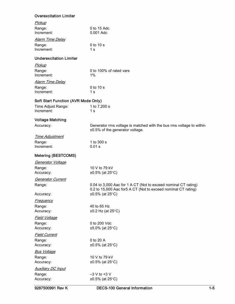
Overexcitation Limiter
Range: 0 to 15 Adc Pickup
Increment: 0.001 Adc
Range: 0 to 10 s Alarm Time Delay
Increment: 1 s
Underexcitation Limiter
Range: 0 to 100% of rated vars Pickup
Increment: 1%
Range: 0 to 10 s Alarm Time Delay
Increment: 1 s
Soft Start Function (AVR Mode Only) Time Adjust Range: 1 to 7,200 s Increment: 1 s
Voltage Matching Accuracy: Generator rms voltage is matched with the bus rms voltage to within
±0.5% of the generator voltage.
Range: 1 to 300 s Time Adjustment
Increment: 0.01 s
Metering (BESTCOMS)
Range: 10 V to 79 kV Generator Voltage
Accuracy: ±0.5% (at 25°C)
Range: 0.04 to 3,000 Aac for 1 A CT (Not to exceed nominal CT rating) Generator Current
0.2 to 15,000 Aac for5 A CT (Not to exceed nominal CT rating) Accuracy: ±0.5% (at 25°C)
Range: 40 to 65 Hz Frequency
Accuracy: ±0.2 Hz (at 25°C)
Range: 0 to 200 Vdc Field Voltage
Accuracy: ±5.0% (at 25°C)
Range: 0 to 20 A Field Current
Accuracy: ±0.5% (at 25°C)
Range: 10 V to 79 kV Bus Voltage
Accuracy: ±0.5% (at 25°C)
Range: –3 V to +3 V Auxiliary DC Input
Accuracy: ±0.5% (at 25°C)
1-6 DECS-100 General Information 9287500991 Rev K
Range: 0 to 99 MVA, MW, Mvar Power (Apparent, Real, and Reactive)
Accuracy: ±3.0% (at 25°C)
Range: –1.0 to –0.6, +0.6 to +1.0 Power Factor
Accuracy: ±0.02 at rated current (25°C), CT input ≥10% nominal rating
Range: 0 to 360 degrees Phase Angle
Accuracy: ±2.0 degrees (at 25°C), CT input ≥10% nominal rating
Environment
DECS-100: –40 to 70°C (–40 to 158°F) Operating Temperature
DECS-100: –40 to 85°C (–40 to 185°F) Storage Temperature
CD-ROM: 0 to 50°C (32 to 122°F)
Type Tests Shock: Withstands 20 G in three perpendicular planes Vibration: Withstands 1.2 G at 5 to 26 Hz Withstands 0.914 mm (0.036 in) double amplitude at 27 to 52 Hz Withstands 5 G at 53 to 500 Hz Salt Fog: Qualified per MIL-STD-810E
Physical
Unit: 1.10 kg (2.42 lb) Weight
Shipping: 1.31 kg (2.88 lb)
Single Unit: 299 x 79 x 146 mm (11.75 x 3.125 x 5.75 in) Shipping Carton Dimensions (W x H x D)
48 Units: 841 x 653 x 352 mm (33.13 x 25.69 x 13.88 in)
Agency Recognition cURus recognition per UL Standard 508 and CSA Standard C22.2 No. 14 Complies with Det Norske Veritas Standard for Certification 2.4
CE Compliance Emissions: CISPR11/EN55011, Level A Electrostatic Discharge (ESD): IEC 1000-4-2/EN 61000-4-2, Level B Radiated Susceptibility: IEC 1000-4-3/EN 61000-4-3, Level A Electrical Fast Transient: IEC 1000-4-4/EN 61000-4-4, Level B Radio Frequency–Conducted: IEC 1000-4-6/EN 61000-4-6, Level A Power Frequency–Magnetic: IEC 1000-4-8/EN 61000-4-8, Level A Dielectric: IEC 255 Surge Immunity: IEC 1000-4-5/EN 61000-4-5, Level B Voltage Dips, Interruptions, and Variations Immunity: IEC 1000-4-11/EN 61000-4-11, Level C
9287500991 Rev K DECS-100 Human-Machine Interface i
SECTION 2 • HUMAN-MACHINE INTERFACE
TABLE OF CONTENTS SECTION 2 • HUMAN-MACHINE INTERFACE ....................................................................................... 2-1
INTRODUCTION.................................................................................................................................... 2-1 FRONT PANEL INDICATORS ............................................................................................................... 2-1
Overexcitation Shutdown ................................................................................................................... 2-1 Generator Overvoltage ....................................................................................................................... 2-1 Loss of Generator Sensing ................................................................................................................. 2-1 Overexcitation Limiting ....................................................................................................................... 2-2 Underexcitation Limiting ..................................................................................................................... 2-2 Var/P.F. Mode Active ......................................................................................................................... 2-2 Manual Mode Active ........................................................................................................................... 2-2 Underfrequency Active ....................................................................................................................... 2-2
COMMUNICATION PORT ..................................................................................................................... 2-2
Figures Figure 2-1. DECS-100 Front Panel Indicators ........................................................................................... 2-1 Figure 2-2. DECS-100 Communication Port Location............................................................................... 2-2

ii DECS-100 Human-Machine Interface 9287500991 Rev K
This page intentionally left blank.
9287500991 Rev K DECS-100 Human-Machine Interface 2-1
SECTION 2 • HUMAN-MACHINE INTERFACE INTRODUCTION The DECS-100 human-machine interface (HMI) consists of front panel indicators and a rear-panel communication port.
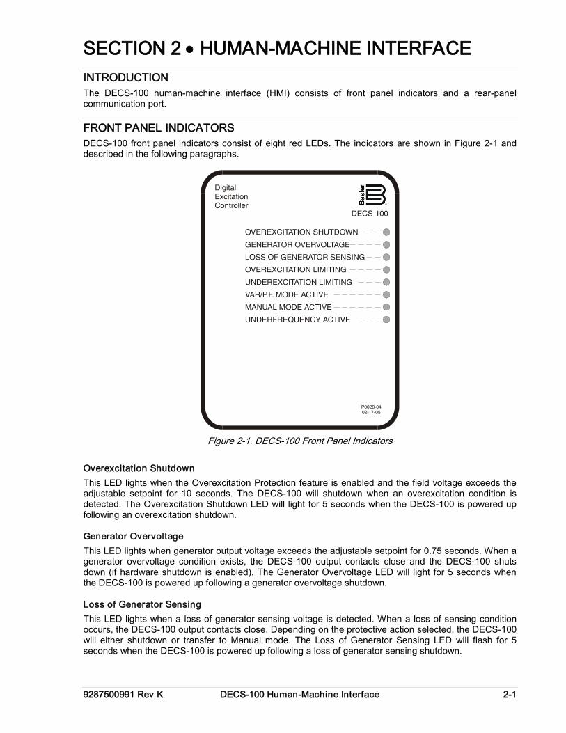
FRONT PANEL INDICATORS DECS-100 front panel indicators consist of eight red LEDs. The indicators are shown in Figure 2-1 and described in the following paragraphs.
Figure 2-1. DECS-100 Front Panel Indicators
Overexcitation Shutdown This LED lights when the Overexcitation Protection feature is enabled and the field voltage exceeds the adjustable setpoint for 10 seconds. The DECS-100 will shutdown when an overexcitation condition is detected. The Overexcitation Shutdown LED will light for 5 seconds when the DECS-100 is powered up following an overexcitation shutdown.
Generator Overvoltage This LED lights when generator output voltage exceeds the adjustable setpoint for 0.75 seconds. When a generator overvoltage condition exists, the DECS-100 output contacts close and the DECS-100 shuts down (if hardware shutdown is enabled). The Generator Overvoltage LED will light for 5 seconds when the DECS-100 is powered up following a generator overvoltage shutdown.
Loss of Generator Sensing This LED lights when a loss of generator sensing voltage is detected. When a loss of sensing condition occurs, the DECS-100 output contacts close. Depending on the protective action selected, the DECS-100 will either shutdown or transfer to Manual mode. The Loss of Generator Sensing LED will flash for 5 seconds when the DECS-100 is powered up following a loss of generator sensing shutdown.
2-2 DECS-100 Human-Machine Interface 9287500991 Rev K
Overexcitation Limiting This LED lights when the field current exceeds the programmed overexcitation limit. It stays lit until the overexcitation condition ceases or the overexcitation time delay expires and the DECS-100 shuts down. The Overexcitation Limiting LED will flash for 5 seconds when the DECS-100 is powered up following an overexcitation limiting shutdown.
Underexcitation Limiting This LED lights when the sensed, reactive power (leading vars) decreases below the programmed underexcitation limit. It stays lit until the underexcitation condition ceases or the underexcitation time delay expires and the DECS-100 shuts down. The Underexcitation Limiting LED will flash for 5 seconds when the DECS-100 is powered up following an underexcitation limiting shutdown.
Var/P.F. Mode Active This LED lights to indicate that the DECS-100 is operating in the optional Var or Power Factor mode of control. Var/Power Factor control is enabled through BESTCOMS software and when the 52J/K contact input is open.
Manual Mode Active This LED lights when the DECS-100 is operating in Manual mode. Manual mode is enabled through BESTCOMS software.
Underfrequency Active This LED lights when the generator frequency decreases below the underfrequency setpoint and the DECS-100 is regulating on the selected volts per hertz curve.
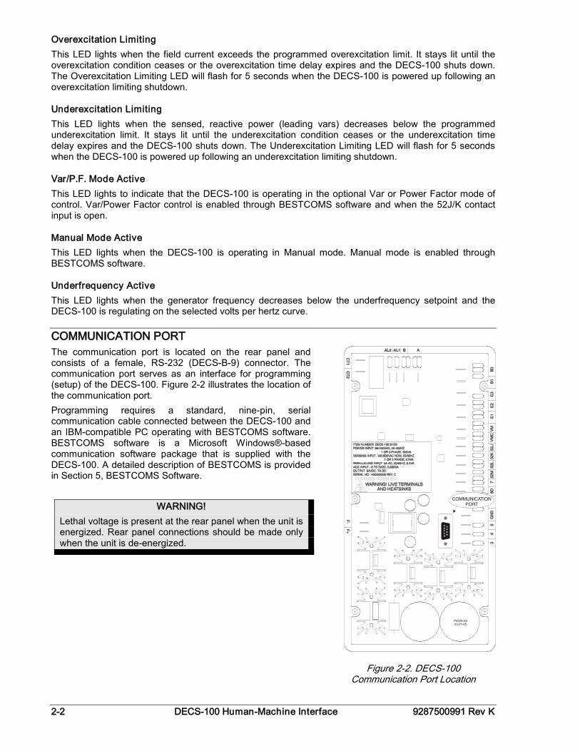
COMMUNICATION PORT The communication port is located on the rear panel and consists of a female, RS-232 (DECS-B-9) connector. The communication port serves as an interface for programming (setup) of the DECS-100. Figure 2-2 illustrates the location of the communication port. Programming requires a standard, nine-pin, serial communication cable connected between the DECS-100 and an IBM-compatible PC operating with BESTCOMS software. BESTCOMS software is a Microsoft Windows®-based communication software package that is supplied with the DECS-100. A detailed description of BESTCOMS is provided in Section 5, BESTCOMS Software.
WARNING! Lethal voltage is present at the rear panel when the unit is energized. Rear panel connections should be made only when the unit is de-energized.
Figure 2-2. DECS-100 Communication Port Location
9287500991 Rev K DECS-100 Functional Description i
SECTION 3 • FUNCTIONAL DESCRIPTION
TABLE OF CONTENTS SECTION 3 • FUNCTIONAL DESCRIPTION ........................................................................................... 3-1
INTRODUCTION.................................................................................................................................... 3-1 DECS-100 FUNCTION BLOCKS ........................................................................................................... 3-1
Analog Input Circuits .......................................................................................................................... 3-1 Bus Voltage..................................................................................................................................... 3-1 Generator Voltage .......................................................................................................................... 3-1 B-Phase Line Current ..................................................................................................................... 3-2 Accessory Input (Auxiliary Adjust) .................................................................................................. 3-2 Field Voltage ................................................................................................................................... 3-2 Field Current ................................................................................................................................... 3-2
Contact Input Circuits ......................................................................................................................... 3-2 Raise ............................................................................................................................................... 3-2 Lower .............................................................................................................................................. 3-2 Var/Power Factor Control (52J/K) Option ....................................................................................... 3-2 Parallel Generator Compensation (52L/M) ..................................................................................... 3-2 Voltage Matching Control Option .................................................................................................... 3-3
RS-232 Communication Port.............................................................................................................. 3-3 Microprocessor ................................................................................................................................... 3-3 Power Input Stage .............................................................................................................................. 3-3 Power Supply ..................................................................................................................................... 3-3 Power Amplifier Stage ........................................................................................................................ 3-3 Front Panel Indicators ........................................................................................................................ 3-3 Relay Output....................................................................................................................................... 3-3
DECS-100 OPERATING FEATURES ................................................................................................... 3-3 Operating Modes ................................................................................................................................ 3-3
Automatic Voltage Regulation Mode .............................................................................................. 3-3 Manual Mode .................................................................................................................................. 3-4 Var Control Mode (Optional) ........................................................................................................... 3-4 Power Factor Control Mode (Optional) ........................................................................................... 3-4
Reactive Droop Compensation .......................................................................................................... 3-4 Underfrequency .................................................................................................................................. 3-4 Protection ........................................................................................................................................... 3-4
Generator Overvoltage ................................................................................................................... 3-5 Loss of Sensing Voltage ................................................................................................................. 3-5 Field Overvoltage (Overexcitation Shutdown) ................................................................................ 3-5
Limiters ............................................................................................................................................... 3-6 Overexcitation Limiting ................................................................................................................... 3-6 Underexcitation Limiting ................................................................................................................. 3-6
Soft Start ............................................................................................................................................. 3-6 Voltage Matching (Optional) ............................................................................................................... 3-6
Figures Figure 3-1. Simplified DECS-100 Block Diagram ...................................................................................... 3-1

ii DECS-100 Functional Description 9287500991 Rev K
This page intentionally left blank.
9287500991 Rev K DECS-100 Functional Description 3-1
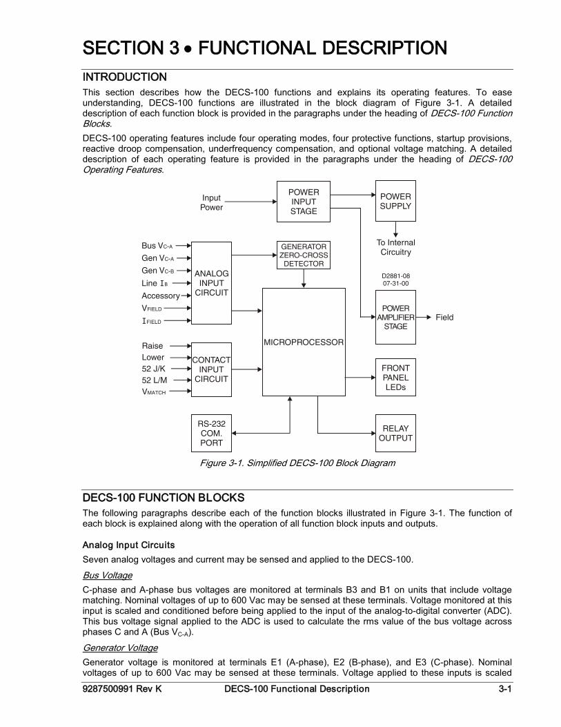
SECTION 3 • FUNCTIONAL DESCRIPTION INTRODUCTION This section describes how the DECS-100 functions and explains its operating features. To ease understanding, DECS-100 functions are illustrated in the block diagram of Figure 3-1. A detailed description of each function block is provided in the paragraphs under the heading of DECS-100 Function Blocks. DECS-100 operating features include four operating modes, four protective functions, startup provisions, reactive droop compensation, underfrequency compensation, and optional voltage matching. A detailed description of each operating feature is provided in the paragraphs under the heading of DECS-100 Operating Features.
Figure 3-1. Simplified DECS-100 Block Diagram
DECS-100 FUNCTION BLOCKS The following paragraphs describe each of the function blocks illustrated in Figure 3-1. The function of each block is explained along with the operation of all function block inputs and outputs.
Analog Input Circuits Seven analog voltages and current may be sensed and applied to the DECS-100.
C-phase and A-phase bus voltages are monitored at terminals B3 and B1 on units that include voltage matching. Nominal voltages of up to 600 Vac may be sensed at these terminals. Voltage monitored at this input is scaled and conditioned before being applied to the input of the analog-to-digital converter (ADC). This bus voltage signal applied to the ADC is used to calculate the rms value of the bus voltage across phases C and A (Bus VC-A).
Bus Voltage
Generator voltage is monitored at terminals E1 (A-phase), E2 (B-phase), and E3 (C-phase). Nominal voltages of up to 600 Vac may be sensed at these terminals. Voltage applied to these inputs is scaled
Generator Voltage
3-2 DECS-100 Functional Description 9287500991 Rev K
and conditioned before being applied to the input of the ADC. The voltage signal from phase C and A (VC-A) of the generator is used by the ADC to calculate the rms value of generator voltage across phases C and A. Likewise, the voltage signal from phase C and B (VC-B) of the generator is used by the ADC to calculate the rms value of generator voltage across phases C and B. The rms value of generator phase B to phase A voltage (VB-A) is calculated by the microprocessor from the phase C to phase A signal (VC-
A)and the phase C to phase B (VC-B) signal. Additionally, the generator phase C to phase A (VC-A) signal is applied to a filtered, zero-cross detector circuit. This signal is applied to the microprocessor and is used to calculate generator frequency.
The phase B line current (IB) signal is developed through a customer supplied current transformer (CT) and monitored through terminals CT1 and CT2. Depending on the option selected, current up to 1 ampere (style number xx1) or 5 amperes (style number xx5) rms may be monitored at these terminals. The current monitored at these terminals is scaled and conditioned by an internal current transformer and active circuitry for use by the ADC. The signal applied to the ADC is used to calculate the rms value of phase B line current.
B-Phase Line Current
Additionally, the phase angle between phase B line current and phase C to phase A generator voltage is calculated for use during droop and var/power factor operation.
This input allows adjustment of the DECS-100 regulation setpoint by the application of a positive or negative dc voltage across terminals A and B. Positive voltage applied to terminal A with respect to terminal B will cause the active mode setpoint to increase. Voltage from –3 to +3 Vdc may be applied to this input. The circuit induces a 1,000-ohm burden on the dc source. The Application of a ±3 Vdc signal corresponds to a ±30 percent change in setpoint.
Accessory Input (Auxiliary Adjust)
Voltage (VFIELD) across the regulator field output terminals, F+ and F–, is monitored, scaled, and conditioned before being applied to the ADC. This signal is used to calculate the dc value of field voltage for use in system protection.
Field Voltage
Current (IFIELD) through the main power output switch is converted to a proportional voltage level. This voltage signal is scaled and conditioned before being applied to the input of the ADC. The result is used to calculate the dc value of field current for use in the Manual mode of operation as well as protection of the system.
Field Current
Contact Input Circuits Five contact input circuits powered from an internal 13 Vdc power supply provide input control from user-supplied, isolated, dry-type contacts.
Closing a contact across terminals 6U and 7 causes the active operating setpoint to increase. This function is active as long as the contact is closed.
Raise
Closing a contact across terminals 6D and 7 causes the active operating setpoint to decrease. This function is active as long as the contact is closed.
Lower
Closing a contact across terminals 52J and 52K disables var/power factor control. An open contact enables the DECS-100 to control the generator reactive power in either the var or the power factor mode. The contact has no effect when this function is not enabled in the software. For more information, see Parallel Generator Compensation (52L/M) and Voltage Matching Control Option.
Var/Power Factor Control (52J/K) Option
Closing a contact across terminals 52L and 52M disables parallel operation. An open contact enables parallel operation and the DECS-100 operates in reactive droop compensation mode.
Parallel Generator Compensation (52L/M)
If the Var/Power Factor Control option is present and is enabled in the software, the 52J/K input has priority. Therefore, if the 52J/K and the 52L/M inputs are both open, the system operates in var/power factor mode. For more information, see Voltage Matching Control Option.
9287500991 Rev K DECS-100 Functional Description 3-3
If the Voltage Matching option is enabled in the software, closing a contact across terminals VM and VMC causes the DECS-100 to operate in the voltage matching mode. An open contact disables voltage matching. Voltage matching is also disabled when either the 52J/K or 52L/M inputs are open.
Voltage Matching Control Option
RS-232 Communication Port The communication port provides the interface for user programming (setup) of the DECS-100. Connection is made to the female RS-232 (DB-9) connector with a user-supplied, standard 9-pin cable. The communication port is optically isolated and is powered from a transformer-isolated supply.
Microprocessor The microprocessor is the heart of the DECS-100 and performs measurement, computation, control, and communication functions by the use of its embedded programming and the nonvolatile settings stored in its memory.
Power Input Stage Input power applied to terminals 3, 4, and 5 is rectified and filtered before being applied to the power amplifier and the power supply. Input power may be single-phase or three-phase in the range of 88 to 250 Vac at a frequency of 50 to 400 hertz. The input power source should be properly fused for the application.
Power Supply The internal switch-mode power supply receives power from the power input stage and supplies power at the required dc voltage levels to the internal circuitry of the DECS-100.
Power Amplifier Stage The power amplifier receives power from the power input stage and supplies a controlled amount of power to the exciter field via terminals F+ and F–. The amount of power supplied to the exciter field is based on gating pulses received from the microprocessor. The power amplifier uses a solid state power switch to provide the required power to the exciter field. Power amplifier output to the field is rated up to 63 Vdc at 7 Adc continuous and 135 Vdc at 15 Adc for 10 seconds.
Front Panel Indicators Eight front-panel LED indicators light to indicate various protective functions and operating modes. Section 2, Human-Machine Interface provides more information about the front panel indicators.
Relay Output A common alarm output contact is provided through terminals AL1 and AL2. This normally open, form A contact annunciates alarm or trip conditions. The relay output is non-latching.
DECS-100 OPERATING FEATURES The following paragraphs describe the characteristics of each DECS-100 operating feature.
Operating Modes The DECS-100 provides up to four modes of operation selectable through BESTCOMS software. Automatic voltage regulation mode and Manual mode are standard features. Var and Power Factor modes are an option.
In Automatic Voltage Regulation (AVR) mode, the DECS-100 regulates rms generator output voltage. This is accomplished by sensing generator output voltage and adjusting dc output excitation current to maintain voltage at the regulation setpoint. The regulation setpoint is adjusted by the Raise and Lower contact inputs, the Accessory input, or through BESTCOMS software. The regulation point may also be modified by the Droop function or the Underfrequency function under certain conditions.
Automatic Voltage Regulation Mode
3-4 DECS-100 Functional Description 9287500991 Rev K
In Manual mode, also known as Field Current Regulation (FCR) mode, the DECS-100 maintains dc excitation current at a set level. The current-level setpoint is adjustable from 0 to 7 Adc in 0.01 Adc increments by the Raise and Lower contact inputs, the optional Accessory input, or through BESTCOMS software.
Manual Mode
In Var Control mode, the DECS-100 maintains generator vars (volt-amperes, reactive) at a set level when paralleling with an infinite bus. The DECS-100 calculates generator vars by using the sensed generator output voltage and current quantities. It then adjusts the dc excitation current to maintain vars at the setpoint. Var control is enabled and disabled through BESTCOMS software. When the software is turned on, var control is enabled or disabled through the Var/Power Factor Control (52J/K) contact input circuit. The var setpoint is adjustable from 100 percent absorb to 100 percent generate through the Raise and Lower contact inputs, the optional Accessory input, or through BESTCOMS software.
Var Control Mode (Optional)
In Power Factor Control mode, the DECS-100 maintains generator power factor at a set level when paralleling with an infinite bus. The DECS-100 calculates generator power factor using the sensed generator output voltage and current quantities and then adjusts the dc excitation current to maintain power factor at the setpoint. Power factor control is enabled or disabled through BESTCOMS software. When the software is turned on, it is enabled or disabled through the Var/Power Factor Control (52J/K) contact input circuit. The power factor setpoint is adjustable between 0.6 lag and 0.6 lead through the Raise and Lower contact inputs, the optional Accessory input, or through BESTCOMS software.
Power Factor Control Mode (Optional)
Reactive Droop Compensation The DECS-100 provides a reactive droop compensation feature to assist in the sharing of reactive load during parallel generator operation. When this feature is enabled, the DECS-100 calculates the reactive portion of the generator load using the sensed generator output voltage and current quantities and then modifies the voltage regulation setpoint accordingly. A unity power factor generator load results in almost no change in generator output voltage. A lagging power factor generator load (inductive) results in a reduction of generator output voltage. A leading power factor generator load (capacitive) results in an increase of generator output voltage. Droop is adjustable up to 10 percent with rated, nominal B-phase line current (1 ampere or 5 amperes applied through terminals CT1 and CT2) and 0.8 power factor. The droop feature is enabled and disabled through the Parallel Generator Compensation contact input circuit (terminals 52L and 52M). Droop is also disabled when operating in var or power factor control modes.
Underfrequency When generator frequency drops below the selected knee frequency setpoint, the voltage setpoint is automatically adjusted by the DECS-100 so that generator voltage follows the selected PU (per unit) V/Hz curve. When operating on the selected PU V/Hz curve, the Underfrequency Active indicator lights on the front panel and in BESTCOMS. Underfrequency control is disabled below 12 hertz. The knee frequency is adjustable from 40 to 65 hertz in 0.1 hertz increments and the PU V/Hz curve may be set at a slope of 0 to 3 in 0.01 steps through BESTCOMS software. A slope of 0 effectively disables the underfrequency function. The DECS-100 has a minimum regulation point of approximately 30 percent of the nominal setpoint.
Protection The DECS-100 includes three protective functions: generator overvoltage, loss of sensing voltage, and field overvoltage. Each protective function has a corresponding front panel indicator that lights when the function is active. An active protective function is also annunciated through BESTCOMS.
CAUTION The Manual mode excitation level must be evaluated prior to enabling this feature. If the level of excitation current is inappropriate for the generator, severe damage to the generator may occur.
9287500991 Rev K DECS-100 Functional Description 3-5
A generator overvoltage condition can be configured (in BESTCOMS) to close the DECS-100 relay output, disable the DECS-100, initiate both actions, or initiate neither action. When the sensed generator voltage increases above the adjustable voltage level setpoint for the duration of the adjustable alarm time delay, the DECS-100 initiates the selected action.
Generator Overvoltage
If the DECS-100 is configured to close the relay output, a generator overvoltage condition will light the front panel and BESTCOMS Generator Overvoltage indicator and close the relay output at terminals AL1 and AL2. If the DECS-100 is configured for hardware shutdown, a generator overvoltage condition will disable the DECS-100 after the alarm time delay expires. When the DECS-100 is powered up following a generator overvoltage shutdown, the Generator Overvoltage indicator will light for five seconds. The voltage level setpoint is adjustable from 100 to 120 % of the system voltage setting. The alarm time delay is adjustable from 0 to 10 seconds.
The DECS-100 monitors the sensed generator output voltage and takes protective action if a loss of sensing voltage is detected. A loss of sensing voltage is detected during the following conditions.
Loss of Sensing Voltage
• The sensed voltage is less than 50 percent of the rated voltage (one-phase or three-phase sensing). • A total loss of any phase occurs (three-phase sensing). • The voltage difference between any phase (line-to-line) and the three-phase average exceeds 20
percent of nominal (three-phase sensing). A time delay of 0 to 25 seconds is adjustable through BESTCOMS software. This delays the protective action in order to allow field forcing in applications that do not sense B-phase generator current. The default time delay setting is 10 seconds. BESTCOMS software allows the selection of one of two protective actions for a loss of sensing. Either a complete shutdown or a transfer to Manual mode may be selected. If shutdown is selected and a loss of sensing occurs, the Loss of Generator Sensing indicator on the front panel and in BESTCOMS lights, the relay output closes, and the DECS-100 shuts down after the adjustable time delay expires. When the DECS-100 is powered up following a loss of generator sensing shutdown, the Loss of Generator Sensing indicator will light for five seconds. However, if the loss of sensing conditions still exists, the DECS-100 will not shut down due to loss of sensing until the soft-start time delay and the loss of sensing time delay expires. If transfer to Manual is selected and a loss of sensing occurs, the relay output closes, and the DECS-100 transfers to the Manual mode of operation after the adjustable time delay expires. The DECS-100 will remain in this mode of operation until switched via BESTCOMS. Prior to selecting transfer to Manual on loss of sensing, it is necessary to determine an appropriate Manual (FCR) mode setpoint level to be transferred to. An inappropriate excitation level could result in severe damage to equipment. This function is disabled when the frequency decreases below 12 hertz or when a generator short circuit condition is detected. A generator short-circuit is determined when the B-phase CT current exceeds three times the per unit value. Loss of sensing shutdown or transfer is not active during the soft-start time.
A field overvoltage condition can be configured (in BESTCOMS) to close the DECS-100 relay output, disable the DECS-100, initiate both actions, or initiate neither action. When the field voltage increases above the adjustable voltage level setpoint for the fixed duration of 10 seconds, the DECS-100 initiates the selected action.
Field Overvoltage (Overexcitation Shutdown)
If the DECS-100 is configured to close the relay output, a field overvoltage condition will light the front panel and BESTCOMS Overexcitation Shutdown indicator and close the relay output at terminals AL1 and AL2. If the DECS-100 is configured for hardware shutdown, a field overvoltage condition will disable the DECS-100 after the 10 second time delay expires. When the DECS-100 is powered up following a field overvoltage shutdown, the Overexcitation Shutdown indicator will light for five seconds. The voltage level setpoint is adjustable from 0 to 250 Vdc. The field overvoltage time delay is fixed at 10 seconds.
3-6 DECS-100 Functional Description 9287500991 Rev K
Limiters DECS-100 limiters consist of an overexcitation limiter (OEL) triggered by an increase in field current and an underexcitation limiter (UEL) triggered by excessive leading vars.
The DECS-100 provides two types of overexcitation limiting: summing point and takeover. Overexcitation Limiting
Summing Point OEL. When the level of field current increases above the adjustable current level setpoint, the front panel and BESTCOMS Overexcitation Limiting indicators light. If the overexcitation condition persists for the duration of the user-adjustable alarm time delay, the relay output at terminals AL1 and AL2 closes. The advantage of a summing-point type of OEL is that it can provide a smooth transition into and out of the limit. Its drawback is that it does not control field current directly, but has to work through the normal voltage regulator, and may be influenced by changes in terminal voltage. Takeover OEL. When takeover-style overexcitation limiting is used, the level of field current at which limiting occurs is determined by an adjustable current level setpoint. If the field current increases above the adjustable current level setpoint, the front panel and BESTCOMS Overexcitation Limiting indicators light and the field current is limited and forced to follow the inverse time curve. The advantage of a takeover type of OEL is that it provides direct control of the exciter field current without relying on the normal voltage regulator’s control action. Its drawback is that it may not provide a smooth transition into and out of the limit. If hardware shutdown is enabled, the DECS-100 will be disabled when the time delay expires. When the DECS-100 is powered up following a shutdown triggered by overexcitation limiting, the Overexcitation Limiting indicator will light for five seconds. The current level setpoint is adjustable from 0 to 15 Adc. The alarm time delay is adjustable from 0 to 10 seconds.
When the level of leading vars increases above the adjustable var level setpoint, the front panel and BESTCOMS Underexcitation Limiting indicators light. If the underexcitation condition persists for the duration of the adjustable alarm time delay, the relay output at terminals AL1 and AL2 closes.
Underexcitation Limiting
If hardware shutdown is enabled, the DECS-100 will be disabled when the time delay expires. When the DECS-100 is powered up following a shutdown triggered by underexcitation limiting, the Underexcitation Limiting indicator will light for five seconds.
The var level setpoint is adjustable from 0 to 100% of the rated vars. The rated var level is determined by the following equation:
3level var rated ××= BAVG IV
where IB is the DECS-100 nominal current sensing rating (1 Aac or 5 Aac) The alarm time delay is adjustable from 0 to 10 seconds.
Soft Start
The DECS-100 also incorporates an adjustable soft start feature that controls the time for generator voltage or field current to ramp to the regulation setpoint. The ramp rate is adjustable from 1 to 7,200 seconds in 1 second increments through BESTCOMS. The underfrequency feature is also active during soft start and takes priority in control of the generator voltage in an effort to minimize voltage overshoot.
Voltage Matching (Optional) Voltage matching is useful when the PT ratios in an application are not matched exactly. Using BESTCOMS to enter the generator PT ratio and bus PT ratio will automatically compensate for the offset.
NOTE The UEL function is active only during parallel operation when the 52J/K contact input or 52L/M contact input is open.
9287500991 Rev K DECS-100 Functional Description 3-7
The DECS-100 voltage matching option automatically matches the rms generator output with the rms bus voltage prior to synchronizing. The DECS-100 compares and matches the generator voltage with the bus voltage by adjusting the dc excitation current. Voltage matching is enabled when the bus voltage is within 10% of the nominal sensing range selected. As long as the values of generator and bus voltage (applies to the DECS-100 voltage sensing inputs) are within the acceptable range, voltage matching can be achieved. The rate at which the DECS-100 matches the generator input level with the bus input level is controlled by a voltage matching speed setting. this setting is adjustable from 1 to 300 seconds in 0.01 second increments. Voltage matching can be disabled by the state of the DECS-100 contact inputs. In BESTCOMS, the 52J/K contact input, 52L/M contact input, or both contact inputs can be configured to enable and disable voltage matching. To enable bus voltage matching, select 52J/K. This will allow droop to remain active. When the utility tie breaker closes, voltage matching will be disabled automatically (via the 52J/K contact input) and var/power factor control will be enabled. Two voltage matching modes are available: Maintain and Revert. When Maintain mode is implemented, the DECS-100 setpoint is maintained at the bus voltage level even when the generator or utility breaker is open. When Revert mode is implemented, the DECS-100 setpoint reverts to its original level when the generator or utility breaker opens. Revert is the default voltage matching mode.
3-8 DECS-100 Functional Description 9287500991 Rev K
This page intentionally left blank.
9287500991 Rev K DECS-100 Installation i
SECTION 4 • INSTALLATION
TABLE OF CONTENTS SECTION 4 • INSTALLATION .................................................................................................................. 4-1
INTRODUCTION.................................................................................................................................... 4-1 MOUNTING ............................................................................................................................................ 4-1 CONNECTIONS..................................................................................................................................... 4-4
DECS-100 Terminations .................................................................................................................... 4-4 Bus Voltage Sensing Inputs (Optional) .............................................................................................. 4-5 Generator Voltage Sensing Inputs ..................................................................................................... 4-5 Phase B Line Current Sensing Input .................................................................................................. 4-5 Accessory Input .................................................................................................................................. 4-5 Raise and Lower Contact Inputs ........................................................................................................ 4-5 Var/Power Factor Control Contact Input (Optional) ........................................................................... 4-5 Parallel Generator Compensation ...................................................................................................... 4-5 Parallel Control and Var/PF Control Inputs ........................................................................................ 4-6 Voltage Matching (Optional) ............................................................................................................... 4-6 Power Supply Inputs .......................................................................................................................... 4-6 Chassis Ground .................................................................................................................................. 4-6 Power (Field) Output .......................................................................................................................... 4-6 Relay Output (Alarm) .......................................................................................................................... 4-6 Communication Port ........................................................................................................................... 4-7 DECS-100 Connections for Typical Applications ............................................................................... 4-7
INSTALLATION FOR CE COMPLIANCE ............................................................................................ 4-13 Mounting ........................................................................................................................................... 4-13 Wiring ............................................................................................................................................... 4-13
PRELIMINARY SETUP ........................................................................................................................ 4-13 Operating Power Considerations During DECS-100 Programming................................................. 4-14
ADJUSTMENTS................................................................................................................................... 4-14
Figures Figure 4-1. DECS-100 Dimensions ........................................................................................................... 4-2 Figure 4-2. Cutout and Drilling Dimensions ............................................................................................... 4-3 Figure 4-3. DECS-100 Terminals .............................................................................................................. 4-4 Figure 4-4. RS-232 Port Pin Assignments ................................................................................................ 4-7 Figure 4-5. Personal Computer to DECS-100 Connections ...................................................................... 4-7 Figure 4-6. Typical Connections for PMG Application with ABC Rotation and Three-Phase Sensing ..... 4-8 Figure 4-7. Typical Connections for PMG Application with ABC Rotation and Single-Phase Sensing .... 4-9 Figure 4-8. Typical Connections for Shunt Application with ABC Rotation and Three-Phase Sensing .. 4-10 Figure 4-9. Typical Connections for Shunt Application with ABC Rotation and Single-Phase Sensing . 4-11 Figure 4-10. Typical Connections for Station Power Application and Three-Phase Sensing ................. 4-12 Figure 4-11. Cross-Current (Reactive Differential) Connections ............................................................. 4-13 Figure 4-12. Operating Power Connections for DECS-100 Programming (Input Voltage >120 Vac)..... 4-14
Tables Table 4-1. Bus Voltage Sensing Terminals ............................................................................................... 4-5 Table 4-2. Generator Voltage Sensing Terminals ..................................................................................... 4-5 Table 4-3. 52L/"M" and 52J/K Control Modes ........................................................................................... 4-6 Table 4-4. Communication Port Pin Functions .......................................................................................... 4-7
ii DECS-100 Installation 9287500991 Rev K
This page intentionally left blank.
9287500991 Rev K DECS-100 Installation 4-1
SECTION 4 • INSTALLATION INTRODUCTION DECS-100 Digital Excitation Control Systems are delivered in sturdy cartons to prevent shipping damage. Upon receipt of a system, check the part number against the requisition and packaging list for agreement. Inspect for damage, and if there is evidence of such, immediately file a claim with the carrier and notify the Basler Electric Regional Sales Office, your Sales Representative or a Sales Representative at Basler Electric, Highland, Illinois. If the unit is not installed immediately, store it in the original shipping package in a moisture and dust free environment.
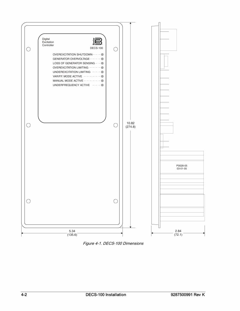
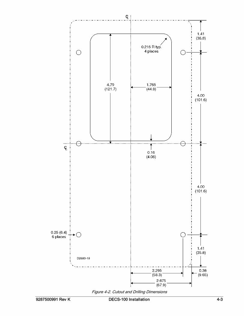
MOUNTING The DECS-100 is normally located in the generator conduit box. It is designed for behind the panel mounting and requires a cutout for front panel viewing. Supplied mounting hardware consists of six #12 thread-forming screws that pass through mounting holes in the conduit box and thread into the plastic shell of the DECS-100. The recommended torque range for the steel mounting screws is 4.07 to 4.52 newton-meters (36 to 40 inch-pounds). The unit must be mounted where the ambient temperature does not exceed the allowable environmental conditions called out in Section 1, General Information, Specifications. DECS-100 package dimensions are shown in Figure 4-1. Cutout and drilling dimensions are shown in Figure 4-2. Drawing dimensions are shown in inches and millimeters (in parenthesis).
4-2 DECS-100 Installation 9287500991 Rev K
Figure 4-1. DECS-100 Dimensions
9287500991 Rev K DECS-100 Installation 4-3
Figure 4-2. Cutout and Drilling Dimensions
4-4 DECS-100 Installation 9287500991 Rev K
CONNECTIONS DECS-100 connections are dependent on the application and excitation scheme. Incorrect wiring may result in damage to the unit. Check the part number to ensure that you have the correct unit before connecting and applying power.
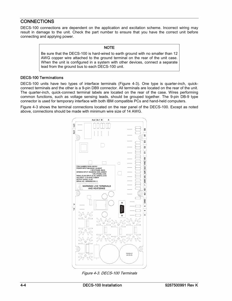
DECS-100 Terminations DECS-100 units have two types of interface terminals (Figure 4-3). One type is quarter-inch, quick-connect terminals and the other is a 9-pin DB9 connector. All terminals are located on the rear of the unit. The quarter-inch, quick-connect terminal labels are located on the rear of the case. Wires performing common functions, such as voltage sensing leads, should be grouped together. The 9-pin DB-9 type connector is used for temporary interface with both IBM compatible PCs and hand-held computers. Figure 4-3 shows the terminal connections located on the rear panel of the DECS-100. Except as noted above, connections should be made with minimum wire size of 14 AWG.
Figure 4-3. DECS-100 Terminals
NOTE Be sure that the DECS-100 is hard-wired to earth ground with no smaller than 12 AWG copper wire attached to the ground terminal on the rear of the unit case. When the unit is configured in a system with other devices, connect a separate lead from the ground bus to each DECS-100 unit.
9287500991 Rev K DECS-100 Installation 4-5
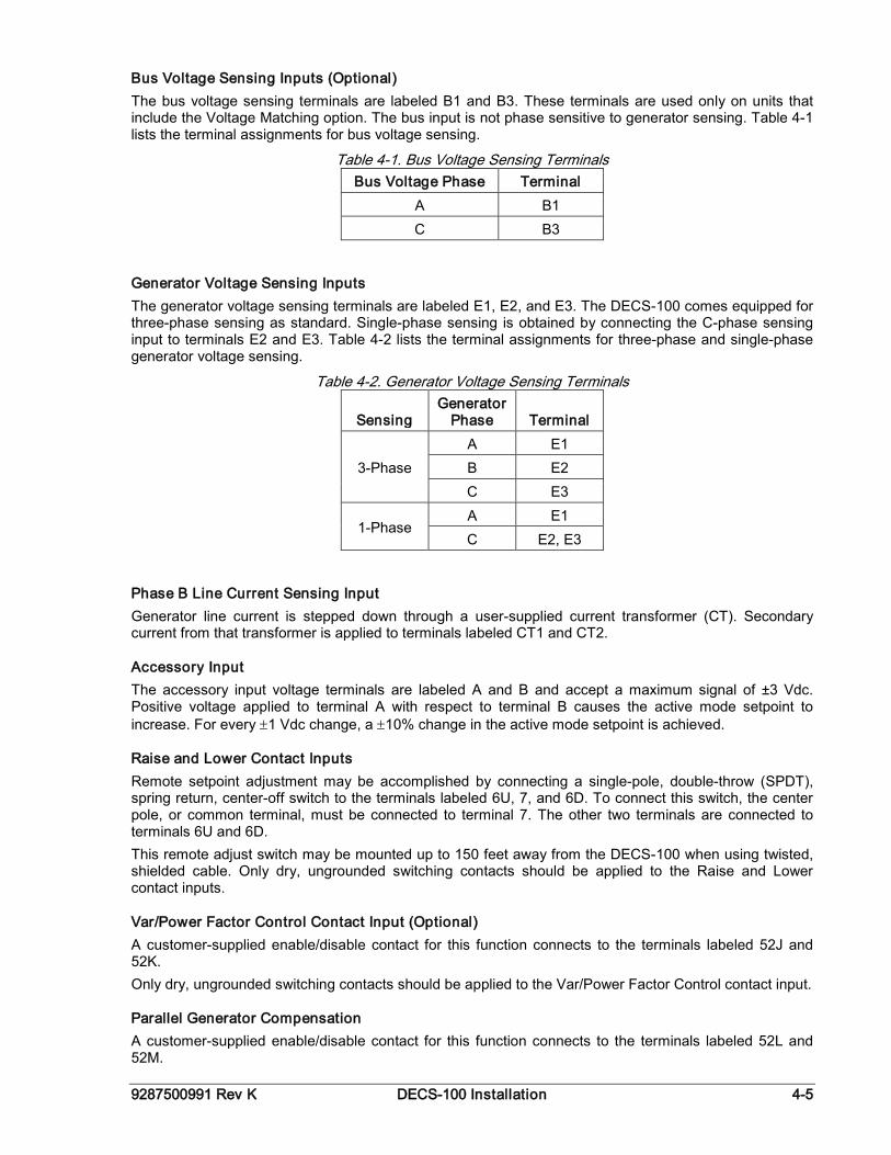
Bus Voltage Sensing Inputs (Optional) The bus voltage sensing terminals are labeled B1 and B3. These terminals are used only on units that include the Voltage Matching option. The bus input is not phase sensitive to generator sensing. Table 4-1 lists the terminal assignments for bus voltage sensing.
Table 4-1. Bus Voltage Sensing Terminals Bus Voltage Phase Terminal
A B1 C B3
Generator Voltage Sensing Inputs The generator voltage sensing terminals are labeled E1, E2, and E3. The DECS-100 comes equipped for three-phase sensing as standard. Single-phase sensing is obtained by connecting the C-phase sensing input to terminals E2 and E3. Table 4-2 lists the terminal assignments for three-phase and single-phase generator voltage sensing.
Table 4-2. Generator Voltage Sensing Terminals
Sensing Generator
Phase Terminal
3-Phase A E1 B E2 C E3
1-Phase A E1 C E2, E3
Phase B Line Current Sensing Input Generator line current is stepped down through a user-supplied current transformer (CT). Secondary current from that transformer is applied to terminals labeled CT1 and CT2.
Accessory Input The accessory input voltage terminals are labeled A and B and accept a maximum signal of ±3 Vdc. Positive voltage applied to terminal A with respect to terminal B causes the active mode setpoint to increase. For every ±1 Vdc change, a ±10% change in the active mode setpoint is achieved.
Raise and Lower Contact Inputs Remote setpoint adjustment may be accomplished by connecting a single-pole, double-throw (SPDT), spring return, center-off switch to the terminals labeled 6U, 7, and 6D. To connect this switch, the center pole, or common terminal, must be connected to terminal 7. The other two terminals are connected to terminals 6U and 6D. This remote adjust switch may be mounted up to 150 feet away from the DECS-100 when using twisted, shielded cable. Only dry, ungrounded switching contacts should be applied to the Raise and Lower contact inputs.
Var/Power Factor Control Contact Input (Optional) A customer-supplied enable/disable contact for this function connects to the terminals labeled 52J and 52K. Only dry, ungrounded switching contacts should be applied to the Var/Power Factor Control contact input.
Parallel Generator Compensation A customer-supplied enable/disable contact for this function connects to the terminals labeled 52L and 52M.
4-6 DECS-100 Installation 9287500991 Rev K
Only dry, ungrounded switching contacts should be applied to the Parallel Generator Compensation contact input.
Parallel Control and Var/PF Control Inputs User-supplied contacts at terminals 52L and 52M determine whether AVR or Droop mode is active. Terminals 52L and 52M typically connect to a 52b auxiliary contact of the generator breaker. User-supplied contacts at terminals 52J and 52K control whether var or power factor correction is active or disabled. Terminals 52J and 52K typically connect to the auxiliary contacts of the utility tie breaker. Table 4-3 lists the operating modes achieved for the different 52L/M and 52J/K contact states. A closed state indicates a continuous contact closure and an open state indicates a continuous open-circuit.
Table 4-3. 52L/M and 52J/K Control Modes DECS-100 Operating Mode 52L/M 52J/K Generator Operating Mode
AVR mode active, no droop, optional var/PF mode disabled
Closed Closed Single unit/stand-alone
Droop mode active, optional var/PF mode disabled
Open Closed Paralleled to the utility grid (droop) or two or more generators islanded (droop or CCC)
Var/PF mode active Open Open Paralleled to utility grid
Voltage Matching (Optional) A customer-supplied enable/disable contact for this function connects to the terminals labeled VM and VMC. Only dry, ungrounded switching contacts should be applied to the Voltage Matching contact input. Voltage matching is also enabled/disabled by the state of the 52J/K and/or 52L/M contact inputs. In BESTCOMS, voltage matching can be configured to be disabled when the 52J/K or 52L/M contact input is open or just the 52J/K contact input is open.
Power Supply Inputs Power input terminals are labeled 3, 4, and 5. Single-phase or three-phase power may be applied. Single-phase power may be applied to any two of the three terminals. The DECS-100 can be powered directly from a variety of sources as long as the DECS-100 input power specifications are followed (see Section 1, General Information, Specifications). Examples of DECS-100 operating power sources are: • Generator (shunt fed) • Permanent magnet generator (PMG) • Auxiliary winding When powering the DECS-100 from a low-impedance power source, special provisions must be made to avoid damage to the DECS-100. Examples of a low-impedance power source include a station service source or power outlet. An Inrush Current Reduction Module, ICRM-7, must be connected between the power source and DECS-100 input power terminals (see Figure 4-10). The ICRM-7 prevents DECS-100 damage by minimizing the level of inrush current. The ICRM-7 can also be used when programming the DECS-100. However, the Preliminary Setup paragraphs illustrate an alternate method for temporarily powering the DECS-100 for programming. More details about the ICRM-7 are available in Basler Electric publication 9387900990.
Chassis Ground The chassis ground terminal is labeled GND.
Power (Field) Output The field output terminals for connection to the generator exciter field are labeled F+ and F–.
Relay Output (Alarm) The common alarm relay output contact may be accessed at the terminals labeled AL1 AND AL2.
9287500991 Rev K DECS-100 Installation 4-7
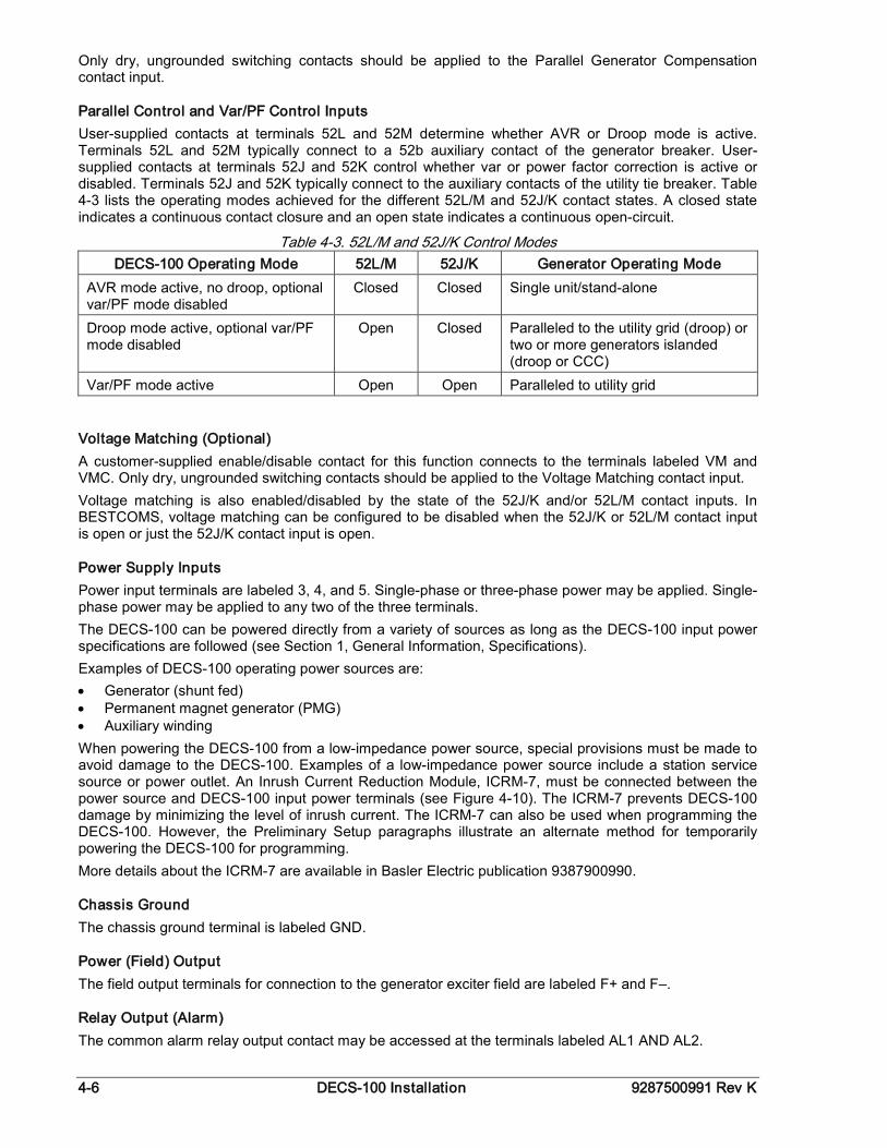
Communication Port The RS-232 port on the rear panel uses a DB-9 female connector. Figure 4-4 Illustrates the pin assignments of the communication port and Table 4-4 Identifies the RS-232 connector pin functions. A standard communication cable terminated with a DB-9 male connector is used for PC interface with the DECS-100 as shown in Figure 4-5.
Figure 4-4. RS-232 Port Pin Assignments
Table 4-4. Communication Port Pin Functions
Pin Function Name Direction 1 N/C — N/A 2 Transmit data TXD From DECS-100 3 Receive data RXD To DECS-100 4 N/C — N/A 5 Signal ground GND N/A 6 N/C — N/A 7 N/C — N/A 8 N/C — N/A 9 N/C — N/A
Figure 4-5. Personal Computer to DECS-100 Connections
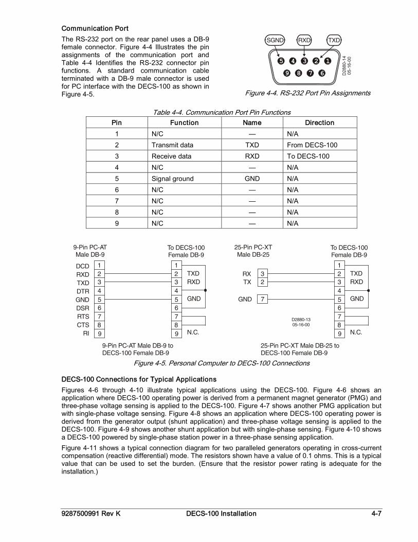
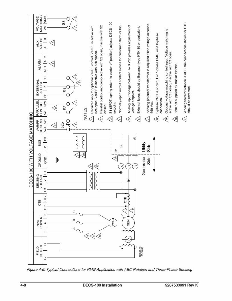
DECS-100 Connections for Typical Applications Figures 4-6 through 4-10 illustrate typical applications using the DECS-100. Figure 4-6 shows an application where DECS-100 operating power is derived from a permanent magnet generator (PMG) and three-phase voltage sensing is applied to the DECS-100. Figure 4-7 shows another PMG application but with single-phase voltage sensing. Figure 4-8 shows an application where DECS-100 operating power is derived from the generator output (shunt application) and three-phase voltage sensing is applied to the DECS-100. Figure 4-9 shows another shunt application but with single-phase sensing. Figure 4-10 shows a DECS-100 powered by single-phase station power in a three-phase sensing application. Figure 4-11 shows a typical connection diagram for two paralleled generators operating in cross-current compensation (reactive differential) mode. The resistors shown have a value of 0.1 ohms. This is a typical value that can be used to set the burden. (Ensure that the resistor power rating is adequate for the installation.)
4-8 DECS-100 Installation 9287500991 Rev K
PO
WER
4C
T1C
T2V
OLT
AG
EE
3E
2E
152
J52
K52
L52
MC
ON
TRO
LC
ON
TRO
L
52b
S2
5
10
2110
Util
itySi
de
A B C
CB
A
52
107
107
10
1086
Gen
erat
orSi
de
CTB
+
GE
N
PM
G
D28
81-0
905
-10-
02
10
OU
TPU
TF-
F+3
6D7
6UA
L 1
AL 2
S1
AB
VM
VM
C
S3
109
54
310
FIE
LDIN
PUT
CTB
SE
NSI
NG
VA
R/P
FA
DJU
ST
EX
TER
NA
LP
ARA
LLEL
DE
CS-
100
WIT
H V
OLT
AGE
MA
TCH
ING
ALAR
MA
UX
.A
DJU
STVO
LTA
GE
MA
TCH
ING
B1
B3
BU
SG
RO
UN
D
GN
D
NO
TES
:
11
3 4 5 6 7 81 2 9 10 11
Req
uire
d on
ly fo
r opt
iona
l Var
/PF
cont
rol.
Var
/PF
is a
ctiv
e w
ith
52b
open
. Var
/PF
is in
activ
e w
ith 5
2b c
lose
d.
Par
alle
l con
trol a
nd d
roop
act
ive
with
S2
open
, ina
ctiv
e w
ith S
2 cl
osed
.
S1
(SP
DT,
spr
ing-
retu
rn to
cen
ter-
off p
ositi
on) a
djus
ts D
EC
S-1
00
setp
oint
.
Nor
mal
ly-o
pen
outp
ut c
onta
ct c
lose
s fo
r cus
tom
er a
larm
or t
rip.
Ana
log
inpu
t vol
tage
bet
wee
n +/
- 3 V
dc p
rovi
des
adju
stm
ent o
f vo
ltage
set
poin
t.
Ext
erna
l fus
es s
houl
d be
Bus
sman
type
KTK
-10
or e
quiv
alen
t.
Sen
sing
pot
entia
l tra
nsfo
rmer
is re
quire
d if
line
volta
ge e
xcee
ds
660
Vac
.
3-ph
ase
PM
G is
sho
wn.
For
1-p
hase
PM
G, o
mit
B-p
hase
co
nnec
tion.
Opt
iona
l vol
tage
mat
chin
g co
ntro
l inp
ut. V
olta
ge m
atch
ing
is
activ
e w
ith S
3 cl
osed
, ina
ctiv
e w
ith S
3 op
en.
Item
not
sup
plie
d by
Bas
ler E
lect
ric.
Whe
n ge
nera
tor r
otat
ion
is A
CB
, the
con
nect
ions
sho
wn
for C
TB
s hou
ld b
e re
vers
ed.
Figure 4-6. Typical Connections for PMG Application with ABC Rotation and Three-Phase Sensing
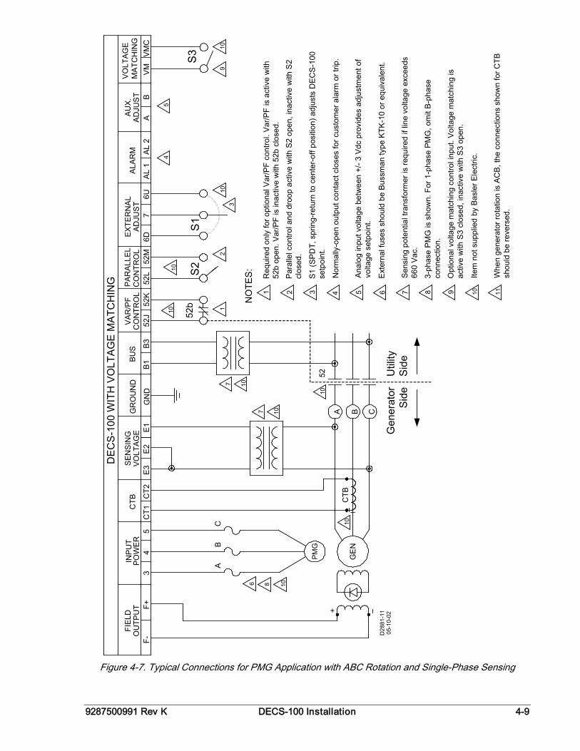
9287500991 Rev K DECS-100 Installation 4-9
CTB
+A
GE
NB C
FIEL
DO
UTP
UT
F-F+
INP
UT
POW
ER
34
ALA
RM
CTB
CT1
CT2
VOLT
AG
ES
ENS
ING
E3
E2
E1
DEC
S-1
00 W
ITH
VO
LTA
GE
MA
TCH
ING
52J
52K
52L
52M
6D7
6U
VAR
/PF
CO
NTR
OL
CO
NTR
OL
ADJU
ST
EXTE
RN
AL
AL
1A
L 2
PAR
ALL
EL
52b
S2
S1
CB
A
PMG
D28
81-1
105
-10-
02
5
10
AU
X.A
DJU
ST
AB
VO
LTAG
EM
ATC
HIN
GV
MV
MC
S3 10
9
54
310
2110
107
10
86
Gen
erat
orS
ide
Util
ityS
ide
NO
TES
:
10
52
107
10
B1B
3
BU
SG
RO
UN
D
GN
D
3 4 5 6 7 81 2 9 10 11
Req
uire
d on
ly fo
r opt
iona
l Var
/PF
cont
rol.
Var
/PF
is a
ctiv
e w
ith
52b
open
. Var
/PF
is in
activ
e w
ith 5
2b c
lose
d.
Par
alle
l con
trol a
nd d
roop
act
ive
with
S2
open
, ina
ctiv
e w
ith S
2 cl
osed
.
S1
(SP
DT,
spr
ing-
retu
rn to
cen
ter-
off p
ositi
on) a
djus
ts D
EC
S-1
00
setp
oint
.
Nor
mal
ly-o
pen
outp
ut c
onta
ct c
lose
s fo
r cus
tom
er a
larm
or t
rip.
Ana
log
inpu
t vol
tage
bet
wee
n +/
- 3 V
dc p
rovi
des
adju
stm
ent o
f vo
ltage
set
poin
t.
Ext
erna
l fus
es s
houl
d be
Bus
sman
type
KTK
-10
or e
quiv
alen
t.
Sen
sing
pot
entia
l tra
nsfo
rmer
is re
quire
d if
line
volta
ge e
xcee
ds
660
Vac
.
3-ph
ase
PM
G is
sho
wn.
For
1-p
hase
PM
G, o
mit
B-p
hase
co
nnec
tion.
Opt
iona
l vol
tage
mat
chin
g co
ntro
l inp
ut. V
olta
ge m
atch
ing
is
activ
e w
ith S
3 cl
osed
, ina
ctiv
e w
ith S
3 op
en.
Item
not
sup
plie
d by
Bas
ler E
lect
ric.
Whe
n ge
nera
tor r
otat
ion
is A
CB
, the
con
nect
ions
sho
wn
for C
TB
s hou
ld b
e re
vers
ed.
Figure 4-7. Typical Connections for PMG Application with ABC Rotation and Single-Phase Sensing
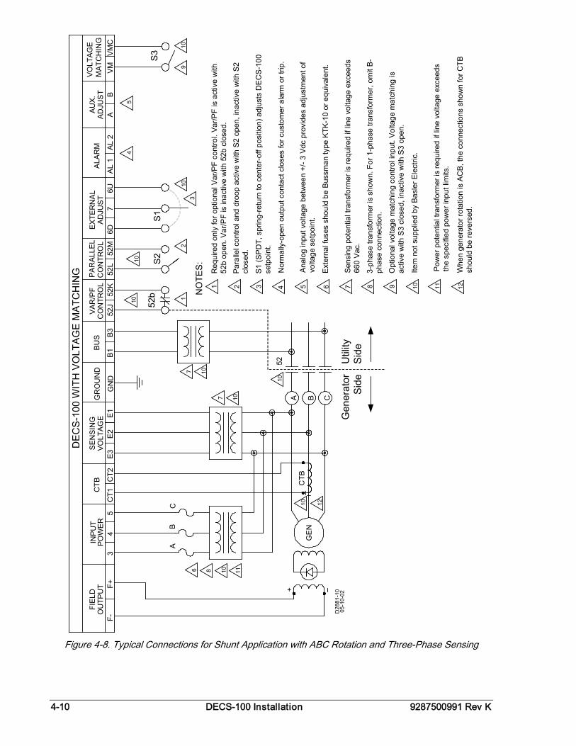
4-10 DECS-100 Installation 9287500991 Rev K
CTB
+A
GE
NB C
FIEL
DO
UTP
UT
F-F+
INP
UT
POW
ER
34
ALA
RM
CTB
CT1
CT2
VOLT
AG
ES
ENS
ING
E3
E2
E1
DEC
S-1
00 W
ITH
VO
LTA
GE
MA
TCH
ING
52J
52K
52L
52M
6D7
6U
VAR
/PF
CO
NTR
OL
CO
NTR
OL
ADJU
ST
EXTE
RN
AL
AL
1A
L 2
PAR
ALL
EL
52b
S2
S1
D28
81-1
005
-10-
02
5
10
AU
X.A
DJU
ST
AB
VO
LTAG
EM
ATC
HIN
GV
MV
MC
S3
109
54
310
2110
107
Gen
erat
orS
ide
Util
ityS
ide
CB
A
10
86 11
10
52
107
10
B1
B3
BU
SG
RO
UN
D
GN
D
12
NO
TES
:
3 4 5 6 7 81 2 9 10 11
Req
uire
d on
ly fo
r opt
iona
l Var
/PF
cont
rol.
Var
/PF
is a
ctiv
e w
ith
52b
open
. Var
/PF
is in
activ
e w
ith 5
2b c
lose
d.
Par
alle
l con
trol a
nd d
roop
act
ive
with
S2
open
, ina
ctiv
e w
ith S
2 cl
osed
.
S1
(SP
DT,
spr
ing-
retu
rn to
cen
ter-
off p
ositi
on) a
djus
ts D
EC
S-1
00
setp
oint
.
Nor
mal
ly-o
pen
outp
ut c
onta
ct c
lose
s fo
r cus
tom
er a
larm
or t
rip.
Ana
log
inpu
t vol
tage
bet
wee
n +/
- 3 V
dc p
rovi
des
adju
stm
ent o
f vo
ltage
set
poin
t.
Ex t
erna
l fus
es s
houl
d be
Bus
sman
type
KTK
-10
or e
quiv
alen
t.
Sen
sing
pot
entia
l tra
nsfo
rmer
is re
quire
d if
line
volta
ge e
xcee
ds
660
Vac
.
3-ph
ase
trans
form
er is
sho
wn.
For
1-p
hase
tran
sfor
mer
, om
it B
-ph
ase
conn
ectio
n.
Opt
iona
l vol
tage
mat
chin
g co
ntro
l inp
ut. V
olta
ge m
atch
ing
is
activ
e w
ith S
3 cl
osed
, ina
ctiv
e w
ith S
3 op
en.
Item
not
sup
plie
d by
Bas
ler E
lect
ric.
Whe
n ge
nera
tor r
otat
ion
is A
CB
, the
con
nect
ions
sho
wn
for C
TB
shou
ld b
e re
vers
ed.
12
Pow
er p
oten
tial t
rans
form
er is
requ
ired
if lin
e vo
ltage
exc
eeds
th
e sp
ecifi
ed p
ower
inpu
t lim
its.
Figure 4-8. Typical Connections for Shunt Application with ABC Rotation and Three-Phase Sensing
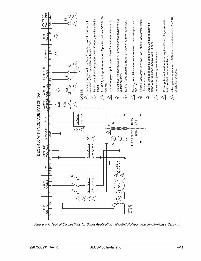
9287500991 Rev K DECS-100 Installation 4-11
CTB
+A
GE
NB C
FIEL
DO
UTP
UT
F-F+
INP
UT
POW
ER
34
ALA
RM
CTB
CT1
CT2
VOLT
AG
ES
ENS
ING
E3
E2
E1
DEC
S-1
00 W
ITH
VO
LTA
GE
MA
TCH
ING
52J
52K
52L
52M
6D7
6U
VAR
/PF
CO
NTR
OL
CO
NTR
OL
ADJU
ST
EXTE
RN
AL
AL
1A
L 2
PAR
ALL
EL
52b
S2
S1
D26
59-1
805
-10-
02
5
10
AU
X.A
DJU
ST
AB
VO
LTAG
EM
ATC
HIN
GV
MV
MC
S3
109
54
310
2110
107
Gen
erat
orS
ide
Util
ityS
ide
CB
A
10
86 11
10
52
107
10
B1
B3
BU
SG
RO
UN
D
GN
D
12
NO
TES:
3 4 5 6 7 81 2 9 10 11
Req
uire
d on
ly fo
r opt
iona
l Var
/PF
cont
rol.
Var
/PF
is a
ctiv
e w
ith
52b
open
. Var
/PF
is in
activ
e w
ith 5
2b c
lose
d.
Par
alle
l con
trol a
nd d
roop
act
ive
with
S2
open
, ina
ctiv
e w
ith S
2 cl
osed
.
S1
(SP
DT,
spr
ing-
retu
rn to
cen
ter-
off p
ositi
on) a
djus
ts D
EC
S-1
00
setp
oint
.
Nor
mal
ly-o
pen
outp
ut c
onta
ct c
lose
s fo
r cus
tom
er a
larm
or t
rip.
Ana
log
inpu
t vol
tage
bet
wee
n +/
- 3 V
dc p
rovi
des
adju
stm
ent o
f vo
ltage
set
poin
t.
Ext
erna
l fus
es s
houl
d be
Bus
sman
type
KTK
-10
or e
quiv
alen
t.
Sen
sing
pot
entia
l tra
nsfo
rmer
is re
quire
d if
line
volta
ge e
xcee
ds
660
Vac
.
3-ph
ase
trans
form
er is
sho
wn.
For
1-p
hase
tran
sfor
mer
, om
it B
-ph
ase
conn
ectio
n.
Opt
iona
l vol
tage
mat
chin
g co
ntro
l inp
ut. V
olta
ge m
atch
ing
is
activ
e w
ith S
3 cl
osed
, ina
ctiv
e w
ith S
3 op
en.
Item
not
sup
plie
d by
Bas
ler E
lect
ric.
Whe
n ge
nera
tor r
otat
ion
is A
CB
, the
con
nect
ions
sho
wn
for C
TB
shou
ld b
e re
vers
ed.
12
Pow
er p
oten
tial t
rans
form
er is
requ
ired
if lin
e vo
ltage
exc
eeds
th
e sp
ecifi
ed p
ower
inpu
t lim
its.
Figure 4-9. Typical Connections for Shunt Application with ABC Rotation and Single-Phase Sensing
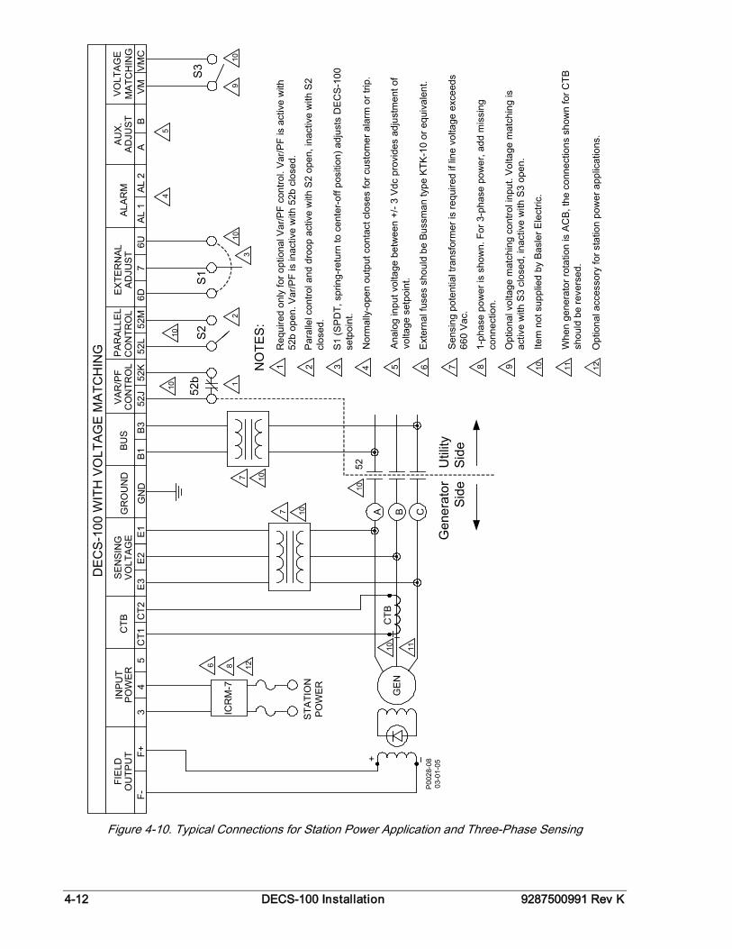
4-12 DECS-100 Installation 9287500991 Rev K
PO
WER
4C
T1C
T2V
OLT
AG
EE
3E
2E
152
J52
K52
L52
MC
ON
TRO
LC
ON
TRO
L
52b
S2
5
10
2110
Util
itySi
de
A B C
52
107
107
10
86
Gen
erat
orSi
de
CTB
+
GE
N
P00
28-0
803
-01-
05
10
OU
TPU
TF-
F+3
6D7
6UA
L 1
AL 2
S1
AB
VM
VM
C
S3
109
54
310
FIE
LDIN
PUT
CTB
SE
NSI
NG
VA
R/P
FA
DJU
ST
EX
TER
NA
LP
ARA
LLEL
DE
CS-
100
WIT
H V
OLT
AGE
MA
TCH
ING
ALAR
MA
UX
.A
DJU
STVO
LTA
GE
MA
TCH
ING
B1
B3
BU
SG
RO
UN
D
GN
D
11
ICR
M-7
12
STA
TIO
NP
OW
ER
NO
TES
:
3 4 5 6 7 81 2 9 10 11
Req
uire
d on
ly fo
r opt
iona
l Var
/PF
cont
rol.
Var
/PF
is a
ctiv
e w
ith
52b
open
. Var
/PF
is in
activ
e w
ith 5
2b c
lose
d.
Par
alle
l con
trol a
nd d
roop
act
ive
with
S2
open
, ina
ctiv
e w
ith S
2 cl
osed
.
S1
(SP
DT,
spr
ing-
retu
rn to
cen
ter-
off p
ositi
on) a
djus
ts D
EC
S-1
00
setp
oint
.
Nor
mal
ly-o
pen
outp
ut c
onta
ct c
lose
s fo
r cus
tom
er a
larm
or t
rip.
Ana
log
inpu
t vol
tage
bet
wee
n +/
- 3 V
dc p
rovi
des
adju
stm
ent o
f vo
ltage
set
poin
t.
Ext
erna
l fus
es s
houl
d be
Bus
sman
type
KTK
-10
or e
quiv
alen
t.
Sen
sing
pot
entia
l tra
nsfo
rmer
is re
quire
d if
line
volta
ge e
xcee
ds
660
Vac
.
1-ph
ase
pow
er is
sho
wn.
For
3-p
hase
pow
er, a
dd m
issi
ng
conn
ectio
n.
Opt
iona
l vol
tage
mat
chin
g co
ntro
l inp
ut. V
olta
ge m
atch
ing
is
activ
e w
ith S
3 cl
osed
, ina
ctiv
e w
ith S
3 op
en.
Item
not
sup
plie
d by
Bas
ler E
lect
ric.
Whe
n ge
nera
tor r
otat
ion
is A
CB
, the
con
nect
ions
sho
wn
for C
TB
shou
ld b
e re
vers
ed.
Opt
iona
l acc
esso
ry fo
r sta
tion
pow
er a
pplic
atio
ns.
12
Figure 4-10. Typical Connections for Station Power Application and Three-Phase Sensing
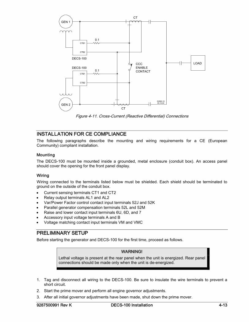
9287500991 Rev K DECS-100 Installation 4-13
GEN 1
GEN 2
CTB1
CTB2
DECS-100
CTB1
CTB2
DECS-100
0.1
0.1
CT
CT
LOADCCCENABLECONTACT
05-19-00D2880-16
Figure 4-11. Cross-Current (Reactive Differential) Connections
INSTALLATION FOR CE COMPLIANCE The following paragraphs describe the mounting and wiring requirements for a CE (European Community) compliant installation.
Mounting The DECS-100 must be mounted inside a grounded, metal enclosure (conduit box). An access panel should cover the opening for the front panel display.
Wiring Wiring connected to the terminals listed below must be shielded. Each shield should be terminated to ground on the outside of the conduit box. • Current sensing terminals CT1 and CT2 • Relay output terminals AL1 and AL2 • Var/Power Factor control contact input terminals 52J and 52K • Parallel generator compensation terminals 52L and 52M • Raise and lower contact input terminals 6U, 6D, and 7 • Accessory input voltage terminals A and B • Voltage matching contact input terminals VM and VMC
PRELIMINARY SETUP Before starting the generator and DECS-100 for the first time, proceed as follows.
1. Tag and disconnect all wiring to the DECS-100. Be sure to insulate the wire terminals to prevent a
short circuit. 2. Start the prime mover and perform all engine governor adjustments. 3. After all initial governor adjustments have been made, shut down the prime mover.
WARNING! Lethal voltage is present at the rear panel when the unit is energized. Rear panel connections should be made only when the unit is de-energized.
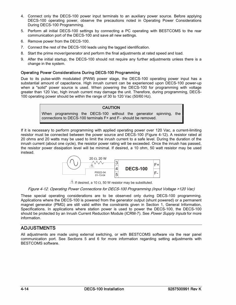
4-14 DECS-100 Installation 9287500991 Rev K
4. Connect only the DECS-100 power input terminals to an auxiliary power source. Before applying DECS-100 operating power, observe the precautions noted in Operating Power Considerations During DECS-100 Programming.
5. Perform all initial DECS-100 settings by connecting a PC operating with BESTCOMS to the rear communication port of the DECS-100 and save all new settings.
6. Remove power from the DECS-100. 7. Connect the rest of the DECS-100 leads using the tagged identification. 8. Start the prime mover/generator and perform the final adjustments at rated speed and load. 9. After the initial startup, the DECS-100 should not require any further adjustments unless there is a
change in the system.
Operating Power Considerations During DECS-100 Programming Due to its pulse-width modulated (PWM) power stage, the DECS-100 operating power input has a substantial amount of capacitance. High inrush current can be experienced upon DECS-100 power-up when a "solid" power source is used. When powering the DECS-100 for programming with voltage greater than 120 Vac, high inrush current may damage the unit. Therefore, during programming, DECS-100 operating power should be within the range of 30 to 120 Vac (50/60 Hz).
If it is necessary to perform programming with applied operating power over 120 Vac, a current-limiting resistor must be connected between the power source and DECS-100 (Figure 4-12). A resistor rated at 20 ohms and 20 watts may be used to limit the inrush current to a safe level. During the duration of the inrush current (about one cycle), the resistor power rating will be exceeded. Once the inrush has passed, the resistor power dissipation level will be minimal. If desired, a 10 ohm, 50 watt resistor may be used instead.
Figure 4-12. Operating Power Connections for DECS-100 Programming (Input Voltage >120 Vac)
These special operating considerations are to be observed only during DECS-100 programming. Applications where the DECS-100 is powered from the generator output (shunt powered) or a permanent magnet generator (PMG) are still valid within the constraints given in Section 1, General Information, Specifications. In applications where station power is used to power the DECS-100, the DECS-100 should be protected by an Inrush Current Reduction Module (ICRM-7). See Power Supply Inputs for more information.
ADJUSTMENTS All adjustments are made using external switching, or with BESTCOMS software via the rear panel communication port. See Sections 5 and 6 for more information regarding setting adjustments with BESTCOMS software.
CAUTION When programming the DECS-100 without the generator spinning, the connections to DECS-100 terminals F+ and F– should be removed.
9287500991 Rev K DECS-100 BESTCOMS Software i
SECTION 5 • BESTCOMS SOFTWARE
TABLE OF CONTENTS SECTION 5 • BESTCOMS SOFTWARE .................................................................................................. 5-1
INTRODUCTION.................................................................................................................................... 5-1 INSTALLATION...................................................................................................................................... 5-1
Installing BESTCOMS ........................................................................................................................ 5-1 Connecting the DECS-100 and PC .................................................................................................... 5-1
STARTING BESTCOMS ........................................................................................................................ 5-1 Establishing Communication .............................................................................................................. 5-2
CHANGING SETTINGS ......................................................................................................................... 5-2 SENDING AND RECEIVING SETTINGS .............................................................................................. 5-3
Sending Settings ................................................................................................................................ 5-3 Receiving Settings .............................................................................................................................. 5-3 Saving Settings to DECS-100 Memory .............................................................................................. 5-3
SETTING DEFINITIONS ........................................................................................................................ 5-3 System Configuration ......................................................................................................................... 5-3
System Settings .............................................................................................................................. 5-3 Setting Adjustments ........................................................................................................................... 5-4
Setpoint Tab ................................................................................................................................... 5-4 Startup Tab ..................................................................................................................................... 5-5
Control Gain ....................................................................................................................................... 5-6 Control Gain Tab ............................................................................................................................ 5-6
Analysis .............................................................................................................................................. 5-8 AVR Tab ......................................................................................................................................... 5-8 FCR Tab ......................................................................................................................................... 5-9 PF Tab .......................................................................................................................................... 5-10 VAR Tab ....................................................................................................................................... 5-11
Protection Settings ........................................................................................................................... 5-12 Protection Tab .............................................................................................................................. 5-13 Limiter Tab .................................................................................................................................... 5-14
Metering, Operation and Alarms ...................................................................................................... 5-14 Operation Tab ............................................................................................................................... 5-15 Alarm/Status Tab .......................................................................................................................... 5-17
PID DATA ............................................................................................................................................. 5-18 PID Calculation Based on Input Values ........................................................................................... 5-18 Adding to the PID List ....................................................................................................................... 5-19 Removing a PID List Record ............................................................................................................ 5-19 Retrieving Existing Data from the PID List ....................................................................................... 5-19
SETTINGS FILES ................................................................................................................................ 5-19 Printing Settings Files ....................................................................................................................... 5-19 Saving Settings Files ........................................................................................................................ 5-20 Uploading Settings Files ................................................................................................................... 5-20
PASSWORD PROTECTION ............................................................................................................... 5-20 Changing the Password ................................................................................................................... 5-20
TERMINATING COMMUNICATION .................................................................................................... 5-21 EMBEDDED FIRMWARE .................................................................................................................... 5-21
Updating the Firmware ..................................................................................................................... 5-21
Figures Figure 5-1. BESTCOMS Title and Version ................................................................................................ 5-1 Figure 5-2. Communication Port Menu Selection ...................................................................................... 5-2 Figure 5-3. Password Dialog Box .............................................................................................................. 5-2 Figure 5-4. Communication Initiation Screen ............................................................................................ 5-2 Figure 5-5. Wait Dialog Box ....................................................................................................................... 5-2 Figure 5-6. System Configuration Screen ................................................................................................. 5-4 Figure 5-7. Setting Adjustments Screen, Setpoint Tab ............................................................................. 5-5 Figure 5-8. Setting Adjustments Screen, Startup Tab ............................................................................... 5-6 Figure 5-9. Control Gain Screen ................................................................................................................ 5-7
ii DECS-100 BESTCOMS Software 9287500991 Rev K
Figure 5-10. Analysis Screen, AVR Tab .................................................................................................... 5-9 Figure 5-11. Analysis Screen, FCR Tab .................................................................................................. 5-10 Figure 5-12. Analysis Screen, PF Tab ..................................................................................................... 5-11 Figure 5-13. Analysis Screen, VAR Tab .................................................................................................. 5-12 Figure 5-14. Protection Settings, Protection Tab .................................................................................... 5-13 Figure 5-15. Protection Settings Screen, Limiter Tab ............................................................................. 5-14 Figure 5-16. Metering, Operation, and Alarms Screen, Operation Tab .................................................. 5-15 Figure 5-17. Metering, Operation, and Alarms Screen, Alarm/Status Tab.............................................. 5-18 Figure 5-18. PID Window ........................................................................................................................ 5-19 Figure 5-19. Settings Upload Dialog Box ................................................................................................ 5-20 Figure 5-20. Password Dialog Box .......................................................................................................... 5-21 Figure 5-21. Software Uploading Advisory Dialog Box ........................................................................... 5-22 Figure 5-22. DECS-100 Embedded Program Loader ............................................................................. 5-22 Figure 5-23. Retrieved DECS-100 Information ....................................................................................... 5-22 Figure 5-24. Settings File Reminder Dialog Box ..................................................................................... 5-23 Figure 5-25. Open Dialog Box ................................................................................................................. 5-23 Figure 5-26. File Transfer Progress ......................................................................................................... 5-23 Figure 5-27. DECS-100 Information After Upload ................................................................................... 5-24
Tables Table 5-1. DECS-100 Stability Range Settings ......................................................................................... 5-7 Table 5-2. Analysis Screen Tab Combinations ......................................................................................... 5-8
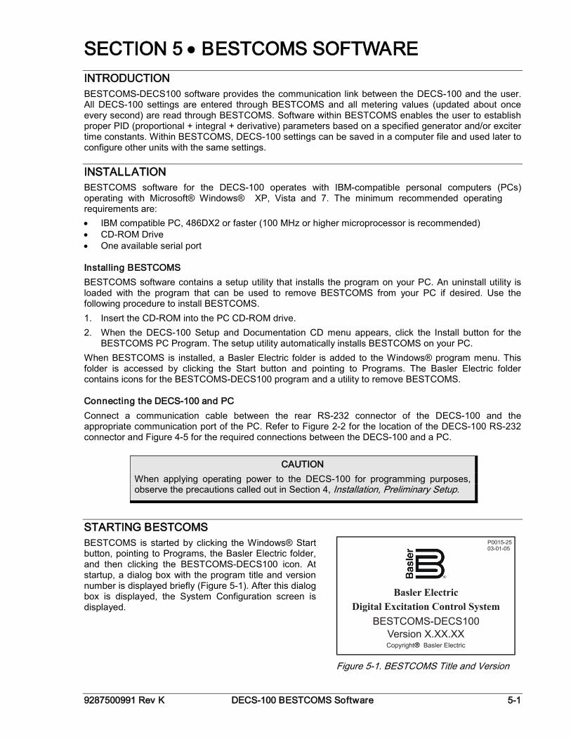
9287500991 Rev K DECS-100 BESTCOMS Software 5-1
SECTION 5 • BESTCOMS SOFTWARE INTRODUCTION BESTCOMS-DECS100 software provides the communication link between the DECS-100 and the user. All DECS-100 settings are entered through BESTCOMS and all metering values (updated about once every second) are read through BESTCOMS. Software within BESTCOMS enables the user to establish proper PID (proportional + integral + derivative) parameters based on a specified generator and/or exciter time constants. Within BESTCOMS, DECS-100 settings can be saved in a computer file and used later to configure other units with the same settings.
INSTALLATION BESTCOMS software for the DECS-100 operates with IBM-compatible personal computers (PCs) operating with Microsoft® Windows® XP, Vista and 7. The minimum recommended operating requirements are: • IBM compatible PC, 486DX2 or faster (100 MHz or higher microprocessor is recommended) • CD-ROM Drive • One available serial port
Installing BESTCOMS BESTCOMS software contains a setup utility that installs the program on your PC. An uninstall utility is loaded with the program that can be used to remove BESTCOMS from your PC if desired. Use the following procedure to install BESTCOMS. 1. Insert the CD-ROM into the PC CD-ROM drive. 2. When the DECS-100 Setup and Documentation CD menu appears, click the Install button for the
BESTCOMS PC Program. The setup utility automatically installs BESTCOMS on your PC. When BESTCOMS is installed, a Basler Electric folder is added to the Windows® program menu. This folder is accessed by clicking the Start button and pointing to Programs. The Basler Electric folder contains icons for the BESTCOMS-DECS100 program and a utility to remove BESTCOMS.
Connecting the DECS-100 and PC Connect a communication cable between the rear RS-232 connector of the DECS-100 and the appropriate communication port of the PC. Refer to Figure 2-2 for the location of the DECS-100 RS-232 connector and Figure 4-5 for the required connections between the DECS-100 and a PC.
STARTING BESTCOMS BESTCOMS is started by clicking the Windows® Start button, pointing to Programs, the Basler Electric folder, and then clicking the BESTCOMS-DECS100 icon. At startup, a dialog box with the program title and version number is displayed briefly (Figure 5-1). After this dialog box is displayed, the System Configuration screen is displayed.
Figure 5-1. BESTCOMS Title and Version
CAUTION When applying operating power to the DECS-100 for programming purposes, observe the precautions called out in Section 4, Installation, Preliminary Setup.
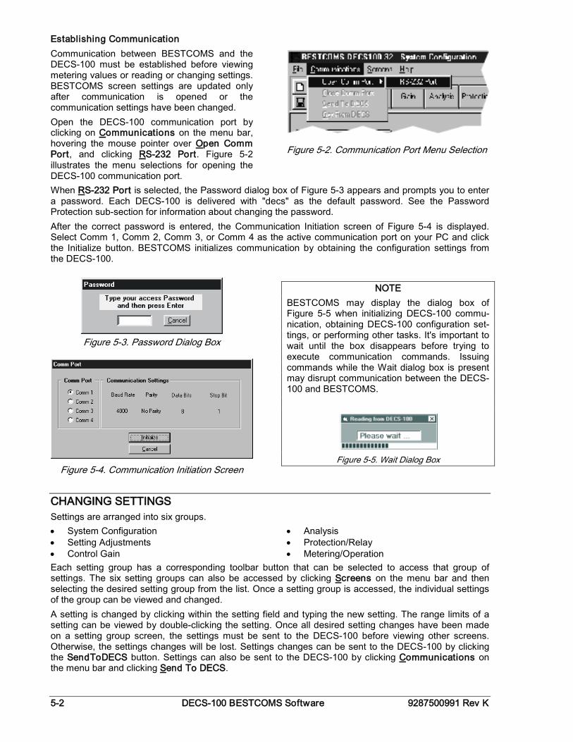
5-2 DECS-100 BESTCOMS Software 9287500991 Rev K
Establishing Communication Communication between BESTCOMS and the DECS-100 must be established before viewing metering values or reading or changing settings. BESTCOMS screen settings are updated only after communication is opened or the communication settings have been changed. Open the DECS-100 communication port by clicking on Communications on the menu bar, hovering the mouse pointer over Open Comm Port, and clicking RS-232 Port. Figure 5-2 illustrates the menu selections for opening the DECS-100 communication port.
Figure 5-2. Communication Port Menu Selection
When RS-232 Port is selected, the Password dialog box of Figure 5-3 appears and prompts you to enter a password. Each DECS-100 is delivered with "decs" as the default password. See the Password Protection sub-section for information about changing the password. After the correct password is entered, the Communication Initiation screen of Figure 5-4 is displayed. Select Comm 1, Comm 2, Comm 3, or Comm 4 as the active communication port on your PC and click the Initialize button. BESTCOMS initializes communication by obtaining the configuration settings from the DECS-100.
Figure 5-3. Password Dialog Box
Figure 5-4. Communication Initiation Screen
NOTE BESTCOMS may display the dialog box of Figure 5-5 when initializing DECS-100 commu-nication, obtaining DECS-100 configuration set-tings, or performing other tasks. It's important to wait until the box disappears before trying to execute communication commands. Issuing commands while the Wait dialog box is present may disrupt communication between the DECS-100 and BESTCOMS.
Figure 5-5. Wait Dialog Box
CHANGING SETTINGS Settings are arranged into six groups. • System Configuration • Setting Adjustments • Control Gain
• Analysis • Protection/Relay • Metering/Operation
Each setting group has a corresponding toolbar button that can be selected to access that group of settings. The six setting groups can also be accessed by clicking Screens on the menu bar and then selecting the desired setting group from the list. Once a setting group is accessed, the individual settings of the group can be viewed and changed. A setting is changed by clicking within the setting field and typing the new setting. The range limits of a setting can be viewed by double-clicking the setting. Once all desired setting changes have been made on a setting group screen, the settings must be sent to the DECS-100 before viewing other screens. Otherwise, the settings changes will be lost. Settings changes can be sent to the DECS-100 by clicking the SendToDECS button. Settings can also be sent to the DECS-100 by clicking Communications on the menu bar and clicking Send To DECS.
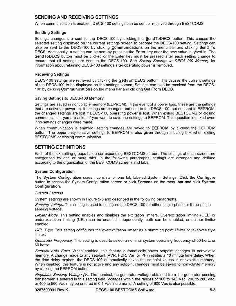
9287500991 Rev K DECS-100 BESTCOMS Software 5-3
SENDING AND RECEIVING SETTINGS When communication is enabled, DECS-100 settings can be sent or received through BESTCOMS.
Sending Settings Settings changes are sent to the DECS-100 by clicking the SendToDECS button. This causes the selected setting displayed on the current settings screen to become the DECS-100 setting. Settings can also be sent to the DECS-100 by clicking Communications on the menu bar and clicking Send To DECS. Additionally, a setting can be sent by pressing the Enter key after the new value is typed in. The SendToDECS button must be clicked or the Enter key must be pressed after each setting change to ensure that all settings are sent to the DECS-100. See Saving Settings to DECS-100 Memory for information about retaining DECS-100 settings after operating power is removed.
Receiving Settings DECS-100 settings are retrieved by clicking the GetFromDECS button. This causes the current settings of the DECS-100 to be displayed on the settings screen. Settings can also be received from the DECS-100 by clicking Communications on the menu bar and clicking Get From DECS.
Saving Settings to DECS-100 Memory Settings are saved in nonvolatile memory (EEPROM). In the event of a power loss, these are the settings that are active at power up. If settings are changed and sent to the DECS-100, but not sent to EEPROM, the changed settings are lost if DECS-100 operating power is lost. When exiting BESTCOMS or closing communication, you are asked if you want to save the settings to EEPROM. This question is asked even if no settings changes were made. When communication is enabled, setting changes are saved to EEPROM by clicking the EEPROM button. The opportunity to save settings to EEPROM is also given through a dialog box when exiting BESTCOMS or closing communication.
SETTING DEFINITIONS Each of the six setting groups has a corresponding BESTCOMS screen. The settings of each screen are categorized by one or more tabs. In the following paragraphs, settings are arranged and defined according to the organization of the BESTCOMS screens and tabs.
System Configuration The System Configuration screen consists of one tab labeled System Settings. Click the Configure button to access the System Configuration screen or click Screens on the menu bar and click System Configuration.
System Settings System settings are shown in Figure 5-6 and described in the following paragraphs. Sensing Voltage. This setting is used to configure the DECS-100 for either single-phase or three-phase sensing voltage. Limiter Mode. This setting enables and disables the excitation limiters. Overexcitation limiting (OEL) or underexcitation limiting (UEL) can be enabled independently, both can be enabled, or neither limiter enabled. OEL Type. This setting configures the overexcitation limiter as a summing point limiter or takeover-style limiter. Generator Frequency. This setting is used to select a nominal system operating frequency of 50 hertz or 60 hertz. Setpoint Auto Save. When enabled, this feature automatically saves setpoint changes in nonvolatile memory. A change made to any setpoint (AVR, FCR, Var, or PF) initiates a 10 minute time delay. When the time delay expires, the DECS-100 automatically saves the setpoint values in nonvolatile memory. When disabled, this feature is not active and any setpoint changes must be saved to nonvolatile memory by clicking the EEPROM button. Regulator Sensing Voltage (V). The nominal, ac generator voltage obtained from the generator sensing transformer is entered in this setting field. Voltages within the ranges of 100 to 140 Vac, 200 to 280 Vac, or 400 to 560 Vac may be entered in 0.1 Vac increments. A setting of 600 Vac is also possible.
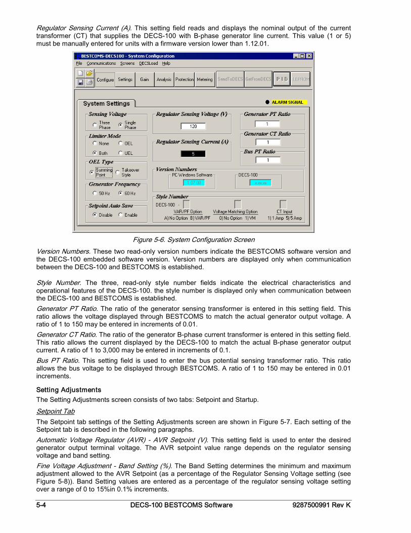
5-4 DECS-100 BESTCOMS Software 9287500991 Rev K
Regulator Sensing Current (A). This setting field reads and displays the nominal output of the current transformer (CT) that supplies the DECS-100 with B-phase generator line current. This value (1 or 5) must be manually entered for units with a firmware version lower than 1.12.01.
Figure 5-6. System Configuration Screen
Version Numbers. These two read-only version numbers indicate the BESTCOMS software version and the DECS-100 embedded software version. Version numbers are displayed only when communication between the DECS-100 and BESTCOMS is established.
Style Number. The three, read-only style number fields indicate the electrical characteristics and operational features of the DECS-100. the style number is displayed only when communication between the DECS-100 and BESTCOMS is established. Generator PT Ratio. The ratio of the generator sensing transformer is entered in this setting field. This ratio allows the voltage displayed through BESTCOMS to match the actual generator output voltage. A ratio of 1 to 150 may be entered in increments of 0.01. Generator CT Ratio. The ratio of the generator B-phase current transformer is entered in this setting field. This ratio allows the current displayed by the DECS-100 to match the actual B-phase generator output current. A ratio of 1 to 3,000 may be entered in increments of 0.1. Bus PT Ratio. This setting field is used to enter the bus potential sensing transformer ratio. This ratio allows the bus voltage to be displayed through BESTCOMS. A ratio of 1 to 150 may be entered in 0.01 increments.
Setting Adjustments The Setting Adjustments screen consists of two tabs: Setpoint and Startup.
Setpoint Tab The Setpoint tab settings of the Setting Adjustments screen are shown in Figure 5-7. Each setting of the Setpoint tab is described in the following paragraphs. Automatic Voltage Regulator (AVR) - AVR Setpoint (V). This setting field is used to enter the desired generator output terminal voltage. The AVR setpoint value range depends on the regulator sensing voltage and band setting. Fine Voltage Adjustment - Band Setting (%). The Band Setting determines the minimum and maximum adjustment allowed to the AVR Setpoint (as a percentage of the Regulator Sensing Voltage setting (see Figure 5-8)). Band Setting values are entered as a percentage of the regulator sensing voltage setting over a range of 0 to 15%in 0.1% increments.
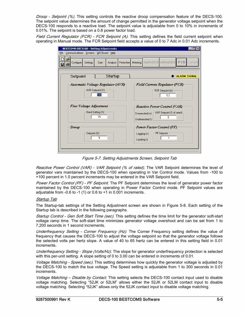
9287500991 Rev K DECS-100 BESTCOMS Software 5-5
Droop - Setpoint (%). This setting controls the reactive droop compensation feature of the DECS-100. The setpoint value determines the amount of change permitted in the generator voltage setpoint when the DECS-100 responds to a reactive load. The setpoint value is adjustable from 0 to 10% in increments of 0.01%. The setpoint is based on a 0.8 power factor load. Field Current Regulator (FCR) - FCR Setpoint (A). This setting defines the field current setpoint when operating in Manual mode. The FCR Setpoint field accepts a value of 0 to 7 Adc in 0.01 Adc increments.
Figure 5-7. Setting Adjustments Screen, Setpoint Tab
Reactive Power Control (VAR) - VAR Setpoint (% of rated). The VAR Setpoint determines the level of generator vars maintained by the DECS-100 when operating in Var Control mode. Values from -100 to +100 percent in 1.0 percent increments may be entered in the VAR Setpoint field. Power Factor Control (PF) - PF Setpoint. The PF Setpoint determines the level of generator power factor maintained by the DECS-100 when operating in Power Factor Control mode. PF Setpoint values are adjustable from -0.6 to -1 (1) or 0.6 to +1 in 0.001 increments.
Startup Tab The Startup-tab settings of the Setting Adjustment screen are shown in Figure 5-8. Each setting of the Startup tab is described in the following paragraphs. Startup Control - Gen Soft Start Time (sec). This setting defines the time limit for the generator soft-start voltage ramp time. The soft-start time minimizes generator voltage overshoot and can be set from 1 to 7,200 seconds in 1 second increments. Underfrequency Setting - Corner Frequency (Hz). The Corner Frequency setting defines the value of frequency that causes the DECS-100 to adjust the voltage setpoint so that the generator voltage follows the selected volts per hertz slope. A value of 40 to 65 hertz can be entered in this setting field in 0.01 increments. Underfrequency Setting - Slope (Volts/Hz). The slope for generator underfrequency protection is selected with this per-unit setting. A slope setting of 0 to 3.00 can be entered in increments of 0.01. Voltage Matching - Speed (sec). This setting determines how quickly the generator voltage is adjusted by the DECS-100 to match the bus voltage. The Speed setting is adjustable from 1 to 300 seconds in 0.01 increments. Voltage Matching – Disable by Contact. This setting selects the DECS-100 contact input used to disable voltage matching. Selecting “52JK or 52LM” allows either the 52JK or 52LM contact input to disable voltage matching. Selecting “52JK” allows only the 52JK contact input to disable voltage matching.
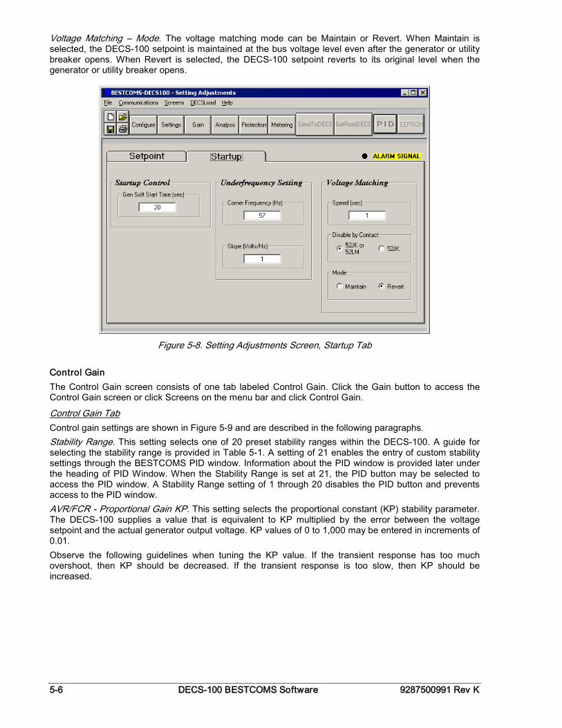
5-6 DECS-100 BESTCOMS Software 9287500991 Rev K
Voltage Matching – Mode. The voltage matching mode can be Maintain or Revert. When Maintain is selected, the DECS-100 setpoint is maintained at the bus voltage level even after the generator or utility breaker opens. When Revert is selected, the DECS-100 setpoint reverts to its original level when the generator or utility breaker opens.
Figure 5-8. Setting Adjustments Screen, Startup Tab
Control Gain The Control Gain screen consists of one tab labeled Control Gain. Click the Gain button to access the Control Gain screen or click Screens on the menu bar and click Control Gain.
Control Gain Tab Control gain settings are shown in Figure 5-9 and are described in the following paragraphs. Stability Range. This setting selects one of 20 preset stability ranges within the DECS-100. A guide for selecting the stability range is provided in Table 5-1. A setting of 21 enables the entry of custom stability settings through the BESTCOMS PID window. Information about the PID window is provided later under the heading of PID Window. When the Stability Range is set at 21, the PID button may be selected to access the PID window. A Stability Range setting of 1 through 20 disables the PID button and prevents access to the PID window. AVR/FCR - Proportional Gain KP. This setting selects the proportional constant (KP) stability parameter. The DECS-100 supplies a value that is equivalent to KP multiplied by the error between the voltage setpoint and the actual generator output voltage. KP values of 0 to 1,000 may be entered in increments of 0.01. Observe the following guidelines when tuning the KP value. If the transient response has too much overshoot, then KP should be decreased. If the transient response is too slow, then KP should be increased.
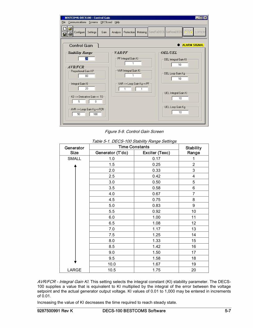
9287500991 Rev K DECS-100 BESTCOMS Software 5-7
Figure 5-9. Control Gain Screen
Table 5-1. DECS-100 Stability Range Settings Generator
Size Time Constants Stability
Range Generator (T’do) Exciter (Texc) SMALL 1.0 0.17 1
1.5 0.25 2 2.0 0.33 3 2.5 0.42 4 3.0 0.50 5 3.5 0.58 6 4.0 0.67 7 4.5 0.75 8 5.0 0.83 9 5.5 0.92 10 6.0 1.00 11 6.5 1.08 12 7.0 1.17 13 7.5 1.25 14 8.0 1.33 15 8.5 1.42 16 9.0 1.50 17 9.5 1.58 18 10.0 1.67 19
LARGE 10.5 1.75 20
AVR/FCR - Integral Gain KI. This setting selects the integral constant (KI) stability parameter. The DECS-100 supplies a value that is equivalent to KI multiplied by the integral of the error between the voltage setpoint and the actual generator output voltage. KI values of 0.01 to 1,000 may be entered in increments of 0.01. Increasing the value of KI decreases the time required to reach steady state.
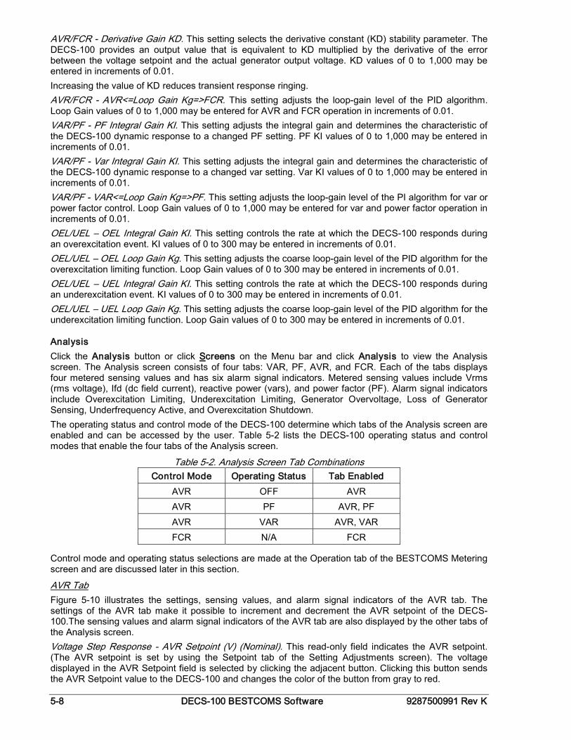
5-8 DECS-100 BESTCOMS Software 9287500991 Rev K
AVR/FCR - Derivative Gain KD. This setting selects the derivative constant (KD) stability parameter. The DECS-100 provides an output value that is equivalent to KD multiplied by the derivative of the error between the voltage setpoint and the actual generator output voltage. KD values of 0 to 1,000 may be entered in increments of 0.01. Increasing the value of KD reduces transient response ringing. AVR/FCR - AVR<=Loop Gain Kg=>FCR. This setting adjusts the loop-gain level of the PID algorithm. Loop Gain values of 0 to 1,000 may be entered for AVR and FCR operation in increments of 0.01. VAR/PF - PF Integral Gain KI. This setting adjusts the integral gain and determines the characteristic of the DECS-100 dynamic response to a changed PF setting. PF KI values of 0 to 1,000 may be entered in increments of 0.01. VAR/PF - Var Integral Gain KI. This setting adjusts the integral gain and determines the characteristic of the DECS-100 dynamic response to a changed var setting. Var KI values of 0 to 1,000 may be entered in increments of 0.01. VAR/PF - VAR<=Loop Gain Kg=>PF. This setting adjusts the loop-gain level of the PI algorithm for var or power factor control. Loop Gain values of 0 to 1,000 may be entered for var and power factor operation in increments of 0.01. OEL/UEL – OEL Integral Gain KI. This setting controls the rate at which the DECS-100 responds during an overexcitation event. KI values of 0 to 300 may be entered in increments of 0.01. OEL/UEL – OEL Loop Gain Kg. This setting adjusts the coarse loop-gain level of the PID algorithm for the overexcitation limiting function. Loop Gain values of 0 to 300 may be entered in increments of 0.01. OEL/UEL – UEL Integral Gain KI. This setting controls the rate at which the DECS-100 responds during an underexcitation event. KI values of 0 to 300 may be entered in increments of 0.01. OEL/UEL – UEL Loop Gain Kg. This setting adjusts the coarse loop-gain level of the PID algorithm for the underexcitation limiting function. Loop Gain values of 0 to 300 may be entered in increments of 0.01.
Analysis Click the Analysis button or click Screens on the Menu bar and click Analysis to view the Analysis screen. The Analysis screen consists of four tabs: VAR, PF, AVR, and FCR. Each of the tabs displays four metered sensing values and has six alarm signal indicators. Metered sensing values include Vrms (rms voltage), Ifd (dc field current), reactive power (vars), and power factor (PF). Alarm signal indicators include Overexcitation Limiting, Underexcitation Limiting, Generator Overvoltage, Loss of Generator Sensing, Underfrequency Active, and Overexcitation Shutdown. The operating status and control mode of the DECS-100 determine which tabs of the Analysis screen are enabled and can be accessed by the user. Table 5-2 lists the DECS-100 operating status and control modes that enable the four tabs of the Analysis screen.
Table 5-2. Analysis Screen Tab Combinations Control Mode Operating Status Tab Enabled
AVR OFF AVR AVR PF AVR, PF AVR VAR AVR, VAR FCR N/A FCR
Control mode and operating status selections are made at the Operation tab of the BESTCOMS Metering screen and are discussed later in this section.
AVR Tab Figure 5-10 illustrates the settings, sensing values, and alarm signal indicators of the AVR tab. The settings of the AVR tab make it possible to increment and decrement the AVR setpoint of the DECS-100.The sensing values and alarm signal indicators of the AVR tab are also displayed by the other tabs of the Analysis screen. Voltage Step Response - AVR Setpoint (V) (Nominal). This read-only field indicates the AVR setpoint. (The AVR setpoint is set by using the Setpoint tab of the Setting Adjustments screen). The voltage displayed in the AVR Setpoint field is selected by clicking the adjacent button. Clicking this button sends the AVR Setpoint value to the DECS-100 and changes the color of the button from gray to red.
9287500991 Rev K DECS-100 BESTCOMS Software 5-9
Voltage Step Response - Increment of AVR Setpoint (V). These two fields indicate the increase that occurs to the AVR setpoint when the corresponding Increment button is clicked. The "% increase" field is used to set and indicate the percentage that the AVR setpoint is increased when the Increment button is clicked. The "AVR Setpoint =" field indicates the value of voltage that corresponds to the "% increase" field. Any setpoint value within range or higher than the setpoint value can be typed into the "AVR Setpoint ="field, which updates the "% increase" field. The AVR setpoint changes to this value when the adjacent button is clicked. When clicked, the Increment button changes from gray to red to indicate that the AVR setpoint has increased to the value in the "AVR Setpoint =" field.
Figure 5-10. Analysis Screen, AVR Tab
Voltage Step Response - Decrement of AVR Setpoint (V). These two fields indicate the change that will occur to the AVR setpoint when the corresponding Decrement button is clicked. The "% decrease" field is used to set and indicate the percentage (0 to 10%) that the AVR setpoint is decreased when the Decrement button is clicked. The "AVR Setpoint =" field indicates the value of voltage that corresponds to the "% decrease" field. Any setpoint value within range or lower than the setpoint value can be typed into the "AVR Setpoint =" field, which updates the "% decrease" field. The AVR setpoint changes to this value when the adjacent button is clicked. When clicked, the Decrement button changes from gray to red to indicate that the AVR setpoint has decreased to the value in the "AVR Setpoint =" field. Voltage Step Response - Meter Value. This field and the dial pointer indicate the value of the selected AVR setpoint. When the AVR setpoint is changed by clicking the increment, decrement, or setpoint button, the meter value field and dial pointer indicate the new setpoint value. A new AVR setpoint can be typed directly into the Meter Value field or selected by dragging the dial pointer to the desired value. The new value is sent to the DECS-100 by clicking the Send button. Voltage Step Response - Current Setpoint. The active DECS-100 setpoint (adjusted by using any of the previously mentioned methods) is displayed in this field. To return the AVR setpoint to the nominal setting, the button adjacent to the "AVR Setpoint (V) (Nominal)" field should be clicked. If the AVR tab is left to view other tabs or screens without returning the AVR setpoint to nominal, an AVR dialog box appears. Clicking the Yes button returns the AVR setpoint to nominal. Clicking No maintains the AVR setpoint at the current value.
FCR Tab Figure 5-11 illustrates the settings, sensing values, and alarm signal indicators of the FCR tab. The settings of the FCR tab make it possible to increment and decrement the FCR setpoint of the DECS-100. The sensing values and alarm signal indicators of the FCR tab are also displayed by the other tabs of the Analysis screen.
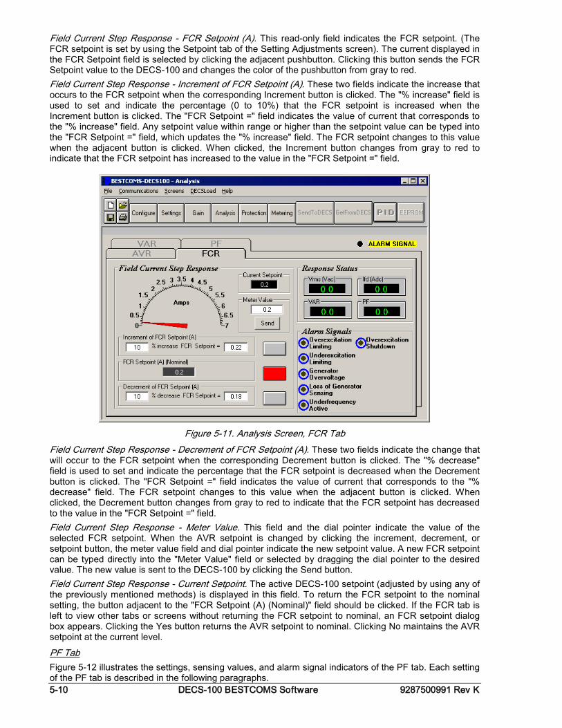
5-10 DECS-100 BESTCOMS Software 9287500991 Rev K
Field Current Step Response - FCR Setpoint (A). This read-only field indicates the FCR setpoint. (The FCR setpoint is set by using the Setpoint tab of the Setting Adjustments screen). The current displayed in the FCR Setpoint field is selected by clicking the adjacent pushbutton. Clicking this button sends the FCR Setpoint value to the DECS-100 and changes the color of the pushbutton from gray to red. Field Current Step Response - Increment of FCR Setpoint (A). These two fields indicate the increase that occurs to the FCR setpoint when the corresponding Increment button is clicked. The "% increase" field is used to set and indicate the percentage (0 to 10%) that the FCR setpoint is increased when the Increment button is clicked. The "FCR Setpoint =" field indicates the value of current that corresponds to the "% increase" field. Any setpoint value within range or higher than the setpoint value can be typed into the "FCR Setpoint =" field, which updates the "% increase" field. The FCR setpoint changes to this value when the adjacent button is clicked. When clicked, the Increment button changes from gray to red to indicate that the FCR setpoint has increased to the value in the "FCR Setpoint =" field.
Figure 5-11. Analysis Screen, FCR Tab
Field Current Step Response - Decrement of FCR Setpoint (A). These two fields indicate the change that will occur to the FCR setpoint when the corresponding Decrement button is clicked. The "% decrease" field is used to set and indicate the percentage that the FCR setpoint is decreased when the Decrement button is clicked. The "FCR Setpoint =" field indicates the value of current that corresponds to the "% decrease" field. The FCR setpoint changes to this value when the adjacent button is clicked. When clicked, the Decrement button changes from gray to red to indicate that the FCR setpoint has decreased to the value in the "FCR Setpoint =" field. Field Current Step Response - Meter Value. This field and the dial pointer indicate the value of the selected FCR setpoint. When the AVR setpoint is changed by clicking the increment, decrement, or setpoint button, the meter value field and dial pointer indicate the new setpoint value. A new FCR setpoint can be typed directly into the "Meter Value" field or selected by dragging the dial pointer to the desired value. The new value is sent to the DECS-100 by clicking the Send button. Field Current Step Response - Current Setpoint. The active DECS-100 setpoint (adjusted by using any of the previously mentioned methods) is displayed in this field. To return the FCR setpoint to the nominal setting, the button adjacent to the "FCR Setpoint (A) (Nominal)" field should be clicked. If the FCR tab is left to view other tabs or screens without returning the FCR setpoint to nominal, an FCR setpoint dialog box appears. Clicking the Yes button returns the AVR setpoint to nominal. Clicking No maintains the AVR setpoint at the current level.
PF Tab Figure 5-12 illustrates the settings, sensing values, and alarm signal indicators of the PF tab. Each setting of the PF tab is described in the following paragraphs.
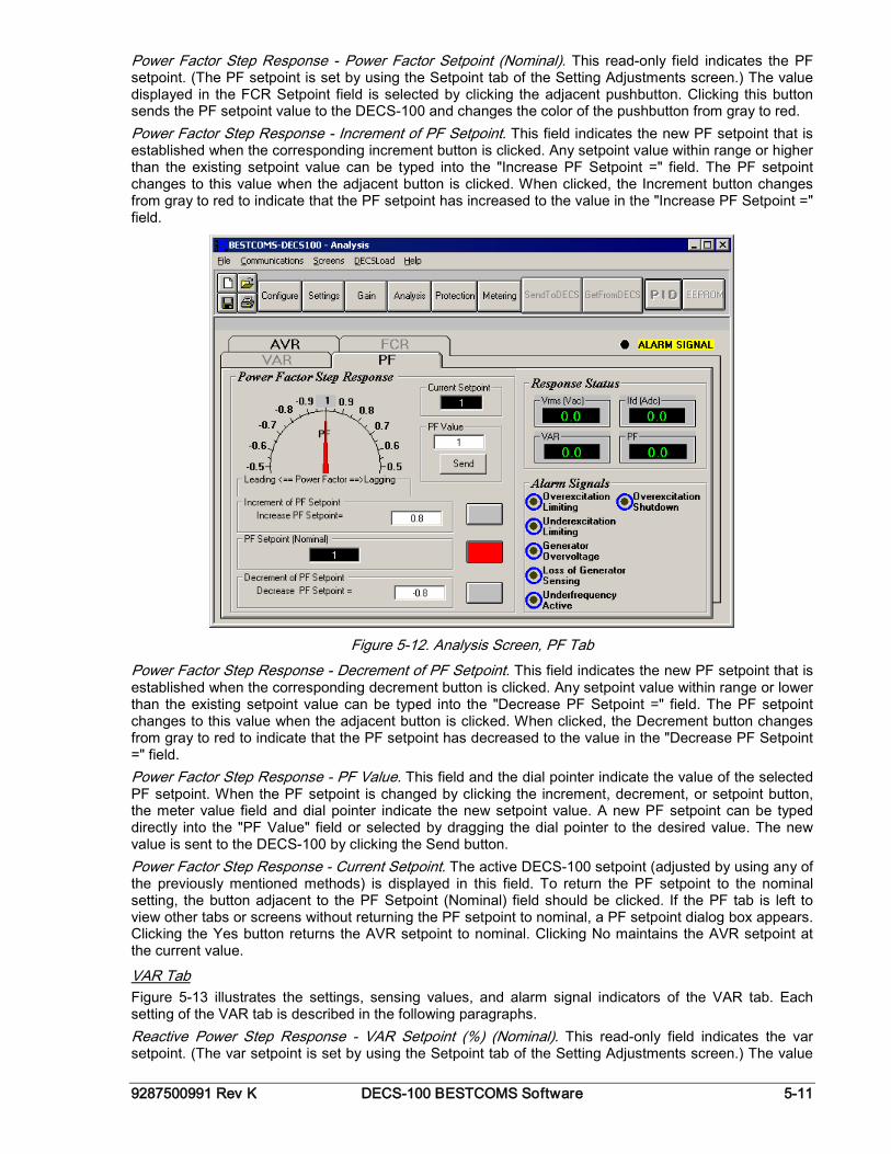
9287500991 Rev K DECS-100 BESTCOMS Software 5-11
Power Factor Step Response - Power Factor Setpoint (Nominal). This read-only field indicates the PF setpoint. (The PF setpoint is set by using the Setpoint tab of the Setting Adjustments screen.) The value displayed in the FCR Setpoint field is selected by clicking the adjacent pushbutton. Clicking this button sends the PF setpoint value to the DECS-100 and changes the color of the pushbutton from gray to red. Power Factor Step Response - Increment of PF Setpoint. This field indicates the new PF setpoint that is established when the corresponding increment button is clicked. Any setpoint value within range or higher than the existing setpoint value can be typed into the "Increase PF Setpoint =" field. The PF setpoint changes to this value when the adjacent button is clicked. When clicked, the Increment button changes from gray to red to indicate that the PF setpoint has increased to the value in the "Increase PF Setpoint =" field.
Figure 5-12. Analysis Screen, PF Tab
Power Factor Step Response - Decrement of PF Setpoint. This field indicates the new PF setpoint that is established when the corresponding decrement button is clicked. Any setpoint value within range or lower than the existing setpoint value can be typed into the "Decrease PF Setpoint =" field. The PF setpoint changes to this value when the adjacent button is clicked. When clicked, the Decrement button changes from gray to red to indicate that the PF setpoint has decreased to the value in the "Decrease PF Setpoint =" field. Power Factor Step Response - PF Value. This field and the dial pointer indicate the value of the selected PF setpoint. When the PF setpoint is changed by clicking the increment, decrement, or setpoint button, the meter value field and dial pointer indicate the new setpoint value. A new PF setpoint can be typed directly into the "PF Value" field or selected by dragging the dial pointer to the desired value. The new value is sent to the DECS-100 by clicking the Send button. Power Factor Step Response - Current Setpoint. The active DECS-100 setpoint (adjusted by using any of the previously mentioned methods) is displayed in this field. To return the PF setpoint to the nominal setting, the button adjacent to the PF Setpoint (Nominal) field should be clicked. If the PF tab is left to view other tabs or screens without returning the PF setpoint to nominal, a PF setpoint dialog box appears. Clicking the Yes button returns the AVR setpoint to nominal. Clicking No maintains the AVR setpoint at the current value.
VAR Tab Figure 5-13 illustrates the settings, sensing values, and alarm signal indicators of the VAR tab. Each setting of the VAR tab is described in the following paragraphs. Reactive Power Step Response - VAR Setpoint (%) (Nominal). This read-only field indicates the var setpoint. (The var setpoint is set by using the Setpoint tab of the Setting Adjustments screen.) The value
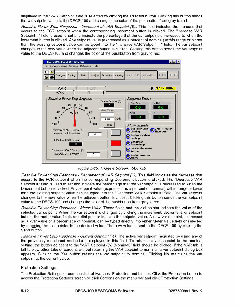
5-12 DECS-100 BESTCOMS Software 9287500991 Rev K
displayed in the "VAR Setpoint" field is selected by clicking the adjacent button. Clicking this button sends the var setpoint value to the DECS-100 and changes the color of the pushbutton from gray to red. Reactive Power Step Response - Increment of VAR Setpoint (%). This field indicates the increase that occurs to the FCR setpoint when the corresponding Increment button is clicked. The "Increase VAR Setpoint =" field is used to set and indicate the percentage that the var setpoint is increased to when the Increment button is clicked. Any setpoint value (expressed as a percent of nominal) within range or higher than the existing setpoint value can be typed into the "Increase VAR Setpoint =" field. The var setpoint changes to the new value when the adjacent button is clicked. Clicking this button sends the var setpoint value to the DECS-100 and changes the color of the pushbutton from gray to red.
Figure 5-13. Analysis Screen, VAR Tab
Reactive Power Step Response - Decrement of VAR Setpoint (%). This field indicates the decrease that occurs to the FCR setpoint when the corresponding Decrement button is clicked. The "Decrease VAR Setpoint =" field is used to set and indicate the percentage that the var setpoint is decreased to when the Decrement button is clicked. Any setpoint value (expressed as a percent of nominal) within range or lower than the existing setpoint value can be typed into the "Decrease VAR Setpoint =" field. The var setpoint changes to the new value when the adjacent button is clicked. Clicking this button sends the var setpoint value to the DECS-100 and changes the color of the pushbutton from gray to red. Reactive Power Step Response - Meter Value. These fields and the dial pointer indicate the value of the selected var setpoint. When the var setpoint is changed by clicking the increment, decrement, or setpoint button, the meter value fields and dial pointer indicate the setpoint value. A new var setpoint, expressed as a kvar value or a percentage of nominal, can be typed directly into either Meter Value field or selected by dragging the dial pointer to the desired value. The new value is sent to the DECS-100 by clicking the Send button. Reactive Power Step Response - Current Setpoint (%). The active var setpoint (adjusted by using any of the previously mentioned methods) is displayed in this field. To return the var setpoint to the nominal setting, the button adjacent to the "VAR Setpoint (%) (Nominal)" field should be clicked. If the VAR tab is left to view other tabs or screens without returning the VAR setpoint to nominal, a var setpoint dialog box appears. Clicking the Yes button returns the var setpoint to nominal. Clicking No maintains the var setpoint at the current value.
Protection Settings The Protection Settings screen consists of two tabs: Protection and Limiter. Click the Protection button to access the Protection Settings screen or click Screens on the menu bar and click Protection Settings.
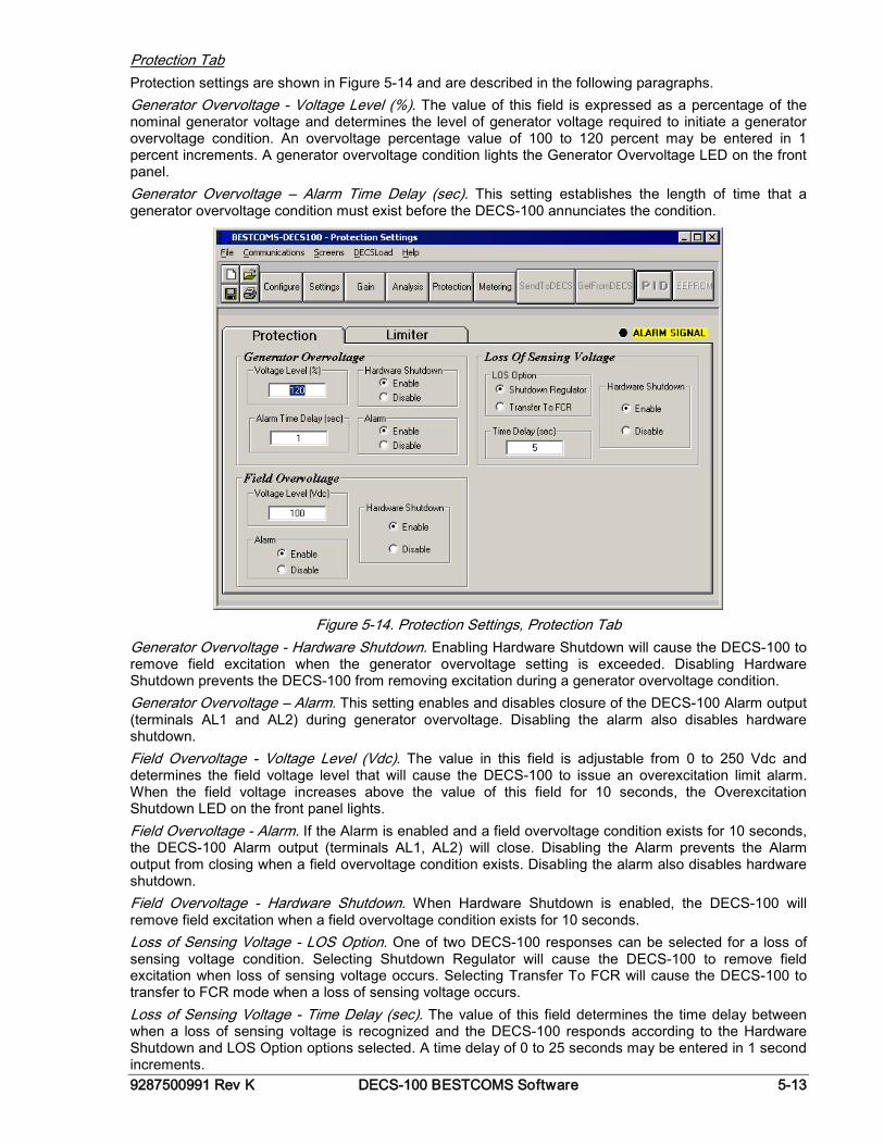
9287500991 Rev K DECS-100 BESTCOMS Software 5-13
Protection Tab Protection settings are shown in Figure 5-14 and are described in the following paragraphs. Generator Overvoltage - Voltage Level (%). The value of this field is expressed as a percentage of the nominal generator voltage and determines the level of generator voltage required to initiate a generator overvoltage condition. An overvoltage percentage value of 100 to 120 percent may be entered in 1 percent increments. A generator overvoltage condition lights the Generator Overvoltage LED on the front panel. Generator Overvoltage – Alarm Time Delay (sec). This setting establishes the length of time that a generator overvoltage condition must exist before the DECS-100 annunciates the condition.
Figure 5-14. Protection Settings, Protection Tab
Generator Overvoltage - Hardware Shutdown. Enabling Hardware Shutdown will cause the DECS-100 to remove field excitation when the generator overvoltage setting is exceeded. Disabling Hardware Shutdown prevents the DECS-100 from removing excitation during a generator overvoltage condition. Generator Overvoltage – Alarm. This setting enables and disables closure of the DECS-100 Alarm output (terminals AL1 and AL2) during generator overvoltage. Disabling the alarm also disables hardware shutdown. Field Overvoltage - Voltage Level (Vdc). The value in this field is adjustable from 0 to 250 Vdc and determines the field voltage level that will cause the DECS-100 to issue an overexcitation limit alarm. When the field voltage increases above the value of this field for 10 seconds, the Overexcitation Shutdown LED on the front panel lights. Field Overvoltage - Alarm. If the Alarm is enabled and a field overvoltage condition exists for 10 seconds, the DECS-100 Alarm output (terminals AL1, AL2) will close. Disabling the Alarm prevents the Alarm output from closing when a field overvoltage condition exists. Disabling the alarm also disables hardware shutdown. Field Overvoltage - Hardware Shutdown. When Hardware Shutdown is enabled, the DECS-100 will remove field excitation when a field overvoltage condition exists for 10 seconds. Loss of Sensing Voltage - LOS Option. One of two DECS-100 responses can be selected for a loss of sensing voltage condition. Selecting Shutdown Regulator will cause the DECS-100 to remove field excitation when loss of sensing voltage occurs. Selecting Transfer To FCR will cause the DECS-100 to transfer to FCR mode when a loss of sensing voltage occurs. Loss of Sensing Voltage - Time Delay (sec). The value of this field determines the time delay between when a loss of sensing voltage is recognized and the DECS-100 responds according to the Hardware Shutdown and LOS Option options selected. A time delay of 0 to 25 seconds may be entered in 1 second increments.
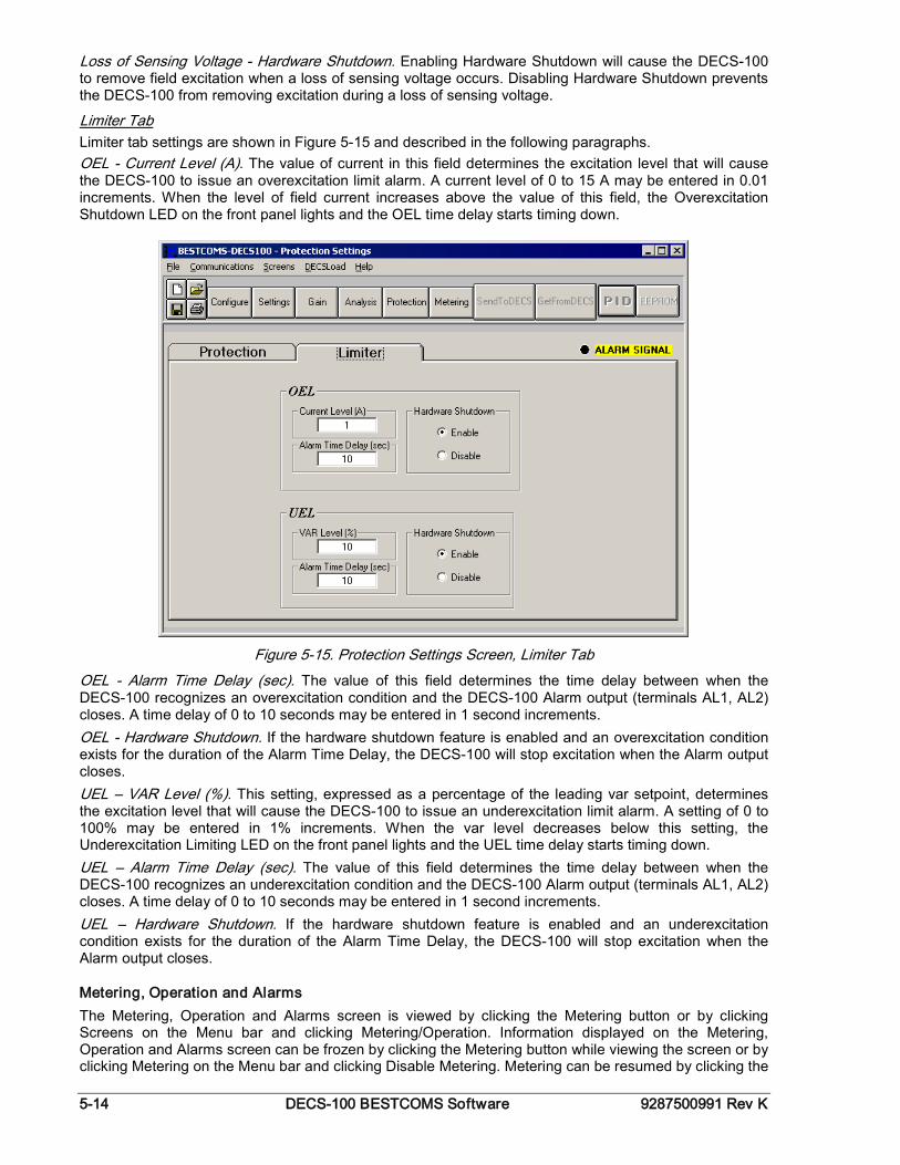
5-14 DECS-100 BESTCOMS Software 9287500991 Rev K
Loss of Sensing Voltage - Hardware Shutdown. Enabling Hardware Shutdown will cause the DECS-100 to remove field excitation when a loss of sensing voltage occurs. Disabling Hardware Shutdown prevents the DECS-100 from removing excitation during a loss of sensing voltage.
Limiter Tab Limiter tab settings are shown in Figure 5-15 and described in the following paragraphs. OEL - Current Level (A). The value of current in this field determines the excitation level that will cause the DECS-100 to issue an overexcitation limit alarm. A current level of 0 to 15 A may be entered in 0.01 increments. When the level of field current increases above the value of this field, the Overexcitation Shutdown LED on the front panel lights and the OEL time delay starts timing down.
Figure 5-15. Protection Settings Screen, Limiter Tab
OEL - Alarm Time Delay (sec). The value of this field determines the time delay between when the DECS-100 recognizes an overexcitation condition and the DECS-100 Alarm output (terminals AL1, AL2) closes. A time delay of 0 to 10 seconds may be entered in 1 second increments. OEL - Hardware Shutdown. If the hardware shutdown feature is enabled and an overexcitation condition exists for the duration of the Alarm Time Delay, the DECS-100 will stop excitation when the Alarm output closes. UEL – VAR Level (%). This setting, expressed as a percentage of the leading var setpoint, determines the excitation level that will cause the DECS-100 to issue an underexcitation limit alarm. A setting of 0 to 100% may be entered in 1% increments. When the var level decreases below this setting, the Underexcitation Limiting LED on the front panel lights and the UEL time delay starts timing down. UEL – Alarm Time Delay (sec). The value of this field determines the time delay between when the DECS-100 recognizes an underexcitation condition and the DECS-100 Alarm output (terminals AL1, AL2) closes. A time delay of 0 to 10 seconds may be entered in 1 second increments. UEL – Hardware Shutdown. If the hardware shutdown feature is enabled and an underexcitation condition exists for the duration of the Alarm Time Delay, the DECS-100 will stop excitation when the Alarm output closes.
Metering, Operation and Alarms The Metering, Operation and Alarms screen is viewed by clicking the Metering button or by clicking Screens on the Menu bar and clicking Metering/Operation. Information displayed on the Metering, Operation and Alarms screen can be frozen by clicking the Metering button while viewing the screen or by clicking Metering on the Menu bar and clicking Disable Metering. Metering can be resumed by clicking the
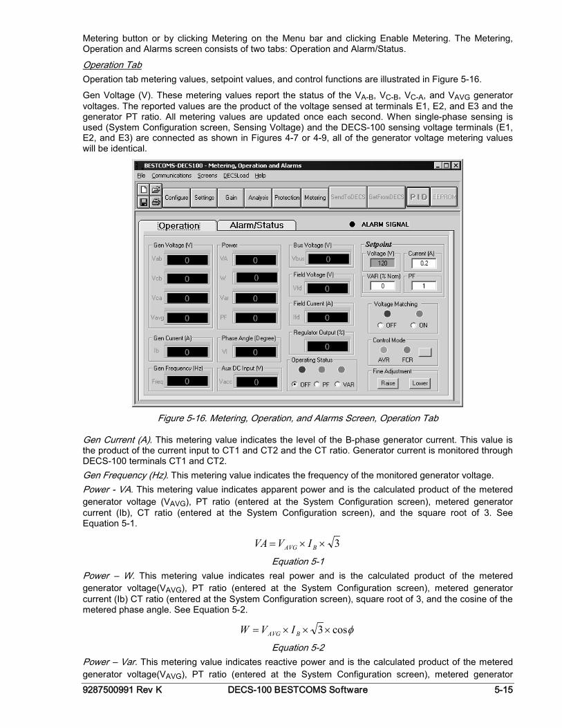
9287500991 Rev K DECS-100 BESTCOMS Software 5-15
Metering button or by clicking Metering on the Menu bar and clicking Enable Metering. The Metering, Operation and Alarms screen consists of two tabs: Operation and Alarm/Status.
Operation Tab Operation tab metering values, setpoint values, and control functions are illustrated in Figure 5-16.
Gen Voltage (V). These metering values report the status of the VA-B, VC-B, VC-A, and VAVG generator voltages. The reported values are the product of the voltage sensed at terminals E1, E2, and E3 and the generator PT ratio. All metering values are updated once each second. When single-phase sensing is used (System Configuration screen, Sensing Voltage) and the DECS-100 sensing voltage terminals (E1, E2, and E3) are connected as shown in Figures 4-7 or 4-9, all of the generator voltage metering values will be identical.
Figure 5-16. Metering, Operation, and Alarms Screen, Operation Tab
Gen Current (A). This metering value indicates the level of the B-phase generator current. This value is the product of the current input to CT1 and CT2 and the CT ratio. Generator current is monitored through DECS-100 terminals CT1 and CT2. Gen Frequency (Hz). This metering value indicates the frequency of the monitored generator voltage. Power - VA. This metering value indicates apparent power and is the calculated product of the metered generator voltage (VAVG), PT ratio (entered at the System Configuration screen), metered generator current (Ib), CT ratio (entered at the System Configuration screen), and the square root of 3. See Equation 5-1.
3××= BAVG IVVA
Equation 5-1 Power – W. This metering value indicates real power and is the calculated product of the metered generator voltage(VAVG), PT ratio (entered at the System Configuration screen), metered generator current (Ib) CT ratio (entered at the System Configuration screen), square root of 3, and the cosine of the metered phase angle. See Equation 5-2.
φcos3×××= BAVG IVW
Equation 5-2 Power – Var. This metering value indicates reactive power and is the calculated product of the metered generator voltage(VAVG), PT ratio (entered at the System Configuration screen), metered generator
5-16 DECS-100 BESTCOMS Software 9287500991 Rev K
current (Ib) CT ratio (entered at the System Configuration screen), square root of 3, and the sine of the metered phase angle. See Equation 5-3.
φsin3var ×××= BAVG IV
Equation 5-3 Power – PF. This metering value indicates the power factor and is the calculated result of dividing the Real Power (W) value by the Apparent Power (VA) value. See Equation 5-4.
VAWPF ÷=
Equation 5-4 Phase Angle (Degree). This metering value indicates the phase angle difference (in degrees) between the generator voltage and the generator current. Aux DC Input (V). This metering value indicates the level of dc control voltage applied from a remote device to DECS-100 terminals A and B. The displayed value correlates to the generator voltage setpoint. Bus Voltage (V). This metering value indicates the amount of bus voltage present at the utility side of the tie circuit breaker. The displayed value is the product of the voltage sensed at terminals B1 and B3 and the bus PT ratio. Field Voltage (V). This metering value indicates the value of voltage being supplied from the DECS-100 output (terminals F+ and F-) to the generator field. Field Current (A). This metering value indicates the amount of current flowing from the DECS-100 output (terminals F+ and F-) to the generator field. Regulator Output (%). This metering value indicates the level of the field output, expressed as a percentage of the maximum rated output. Operating Status. The Operating Status controls and indicators include three buttons and three corresponding indicators. Operating Status buttons are labeled PF, VAR, and OFF. Clicking the PF button changes the color of the adjacent PF indicator to green and causes the DECS-100 to maintain the desired power factor regulation point. The power factor regulation point can be set within the range of 0.6 lead to 0.6 lag. Clicking the VAR button changes the color of the adjacent VAR indicator to green and causes the DECS-100 to maintain the desired var regulation point. The var regulation point can be set within the range of 100 percent absorb to 100 percent generate. Clicking the OFF button changes the color of the adjacent OFF indicator to red and disables power factor and var regulation. Operation of the Operating Status controls is determined by the status of the contacts connected across the DECS-100 Var/PF Control terminals (52J, 52K). When these contacts are open, the Operating Status controls are enabled. Closing the contacts at terminals 52J and 52K disables the Operating Status controls and interrupts regulation of vars or power factor until the contacts are opened again. Setpoint - Voltage (V). This setting field can be used to enter the desired generator output terminal voltage. The voltage setpoint can also be entered at the Setting Adjustments screen, Setpoint tab, Automatic Voltage Regulator (AVR) - AVR Setpoint (V). The background color of this field is green when operating in AVR mode and power factor and var regulation is disabled. Setpoint - Current (A). This setting defines the field current setpoint when operating in FCR mode. The current setpoint can also be entered at the Setting Adjustments screen, Setpoint tab, Field Current Regulator (FCR) - FCR Setpoint. Current values from 0 to 7 Adc may be entered in increments of 0.01 Adc. The background color of this field is green when operating in FCR mode. Setpoint - Var (% of nom.). This setting determines the level of generator vars maintained by the DECS-100 when operating in var mode. The var setpoint can also be entered at the Setting Adjustments screen, Setpoint tab, Reactive Power Control (VAR) - VAR Setpoint (% of nom.). The background color of this field is green when the DECS-100 is operating in AVR mode and is regulating the var setpoint. Setpoint - Power Factor. This setting determines the level of power factor regulation maintained by the DECS-100. The power factor setpoint can also be entered at the Setting Adjustments screen, Setpoint tab, Power Factor Control (PF) - PF Setpoint. Power Factor setpoint values are adjustable from -0.6 to -1 (1) or 0.6 to +1 in 0.001 increments. The background color of this field is green when the DECS-100 is operating in AVR mode and is regulating the power factor setpoint. Voltage Matching. The Voltage Matching controls and indicators consist of two buttons and two adjacent indicators. Clicking the ON button changes the color of the adjacent ON indicator to green and enables voltage matching by the DECS-100. When Voltage Matching is enabled, the DECS-100 automatically
9287500991 Rev K DECS-100 BESTCOMS Software 5-17
adjusts the field current to match the generator output voltage with the bus voltage prior to synchronizing. In order for Voltage Matching to be enabled, the following conditions must be met. • The Parallel Generator Compensation Contacts (terminals 52L and 52M) must be shorted. • The DECS-100 Voltage Matching input must be shorted (terminals VM and VMC). • Var/PF control must be disabled by shorting terminals 52J and 52K (open breaker). • The DECS-100 must be operating in AVR mode. Clicking the OFF button changes the color of the adjacent OFF indicator to red and disables the voltage matching function. Control Mode. Clicking the AVR button changes the color of the adjacent AVR indicator to green and enables the AVR operating mode. When operating in AVR mode, the DECS-100 regulates the generator output voltage at the AVR setpoint. Clicking the FCR button changes the color of the adjacent FCR indicator to green and enables the FCR operating mode. When operating in FCR mode, the DECS-100 maintains the field current at the FCR setpoint. Enabling the FCR mode turns off Voltage Matching. Fine Adjustment. Raise and Lower buttons control the fine adjustment of the operating setpoint. These buttons perform the same function as closing the appropriate set of contacts connected to the External Adjust terminals (6D and 7 to decrease, 6U and 7 to increase) of the DECS-100. For AVR mode, each click of the Raise button increases the voltage setpoint 0.01 volts; each click of the Lower button decreases the voltage setpoint 0.01 volts. The minimum and maximum limits for fine adjustment of the voltage setpoint are controlled by the Regulator Sensing Voltage setting (System Configuration screen) and the Fine Voltage Adjustment - Band setting (Setting Adjustments screen). Fine adjustment of the voltage setpoint can be increased/decreased no higher/lower than the Regulator Sensing Voltage setting plus/minus the Band setting. For example, a Regulator Sensing Voltage setting of 100 volts and a Band setting of 10 percent allows the Fine Adjustment function to increase the voltage setpoint to a maximum of 110 volts and decrease the voltage setpoint to a minimum of 90 volts. For Var, PF, or FCR modes, the Raise and Lower buttons provide fine adjustment over the entire adjustment range.
Alarm/Status Tab The Alarm/Status tab indicators provide the status of DECS-100 protection functions, control modes, and contact inputs. Alarm/Status tab indicators are illustrated in Figure 5-17 and are described in the following paragraphs. Protection Alarms. Six protection alarm indicators provide the status of DECS-100 protection functions. Alarm indicators include Overexcitation Shutdown, Overexcitation Limiting, Underexcitation Limiting, Generator Overvoltage, Loss of Generator Sensing, and Underfrequency. When a DECS-100 protection function detects an alarm condition, the appropriate indicator changes from black to red. Control Status. Two Control Status indicators indicate when the VAR/PF and Manual modes are active. The Manual Mode Active indicator changes from black to red when the FCR control mode is active. The VAR/PF Mode Active indicator changes from black to red when the DECS-100 is operating in AVR mode and correction of power factor or vars is selected. Switch Status. Three Switch Status indicators indicate when the DECS-100 control inputs are open or closed. The 52JK switch open indicator changes from black to red when the user-supplied contacts at terminals 52J and 52K are closed. When this control input is open, selection of PF or VAR mode can be made on the Operation tab of the Metering, Operation, and Alarms screen. The 52LM switch closed indicator changes from black to red when the user-supplied contacts at terminals 52L and 52M are closed. When this control input is closed, parallel control and droop is inactive. The VM switch closed indicator changes from black to red when the user-supplied contacts at terminals VM and VMC are closed. When this control input is closed, the Voltage Matching function is active. Metering Signal. The Metering Signal indicator flashes to indicate when metering is active. A number beside the indicator tracks how many times the metering and status indicators have been updated. When the Metering button is clicked or Metering on the Menu bar is clicked followed by Disable Metering, the Metering Signal indicator stops flashing, the metering update counter stops incrementing, and the metering functions stop being updated.
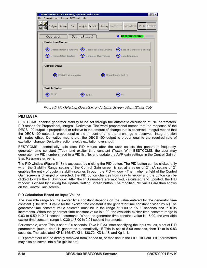
5-18 DECS-100 BESTCOMS Software 9287500991 Rev K
Figure 5-17. Metering, Operation, and Alarms Screen, Alarm/Status Tab
PID DATA BESTCOMS enables generator stability to be set through the automatic calculation of PID parameters. PID stands for Proportional, Integral, Derivative. The word proportional means that the response of the DECS-100 output is proportional or relative to the amount of change that is observed. Integral means that the DECS-100 output is proportional to the amount of time that a change is observed. Integral action eliminates offset. Derivative means that the DECS-100 output is proportional to the required rate of excitation change. Derivative action avoids excitation overshoot. BESTCOMS automatically calculates PID values after the user selects the generator frequency, generator time constant (T'do), and exciter time constant (Texc). With BESTCOMS, the user may generate new PID numbers, add to a PID list file, and update the AVR gain settings in the Control Gain or Step Response screens. The PID window (Figure 5-18) is accessed by clicking the PID button. The PID button can be clicked only when the Stability Range setting of the Control Gain screen is set at a value of 21. (A setting of 21 enables the entry of custom stability settings through the PID window.) Then, when a field of the Control Gain screen is changed or selected, the PID button changes from gray to yellow and the button can be clicked to view the PID window. After the PID numbers are modified, calculated, and updated, the PID window is closed by clicking the Update Setting Screen button. The modified PID values are then shown on the Control Gain screen.
PID Calculation Based on Input Values The available range for the exciter time constant depends on the value entered for the generator time constant. (The default value for the exciter time constant is the generator time constant divided by 6.) The generator time constant value selected must be in the range of 1.00 to 15.00 seconds and in 0.05 increments. When the generator time constant value is 1.00, the available exciter time constant range is 0.03 to 0.50 in 0.01 second increments. When the generator time constant value is 15.00, the available exciter time constant range is 0.30 to 3.00 in 0.01 second increments. For example, when T'do is set at 2.0 seconds, Texc is 0.33. After specifying the input values, a set of PID parameters (output data) is generated automatically. If T'do is set at 5.00 seconds, then Texc is 0.83 seconds. The calculated KP is 155.47, KI is 138.72, KD is 48, and Kg is 1. PID parameters can be directly removed from, added to, or modified in the PID List Data. PID parameters may also be saved into a file (pidlist.dat).
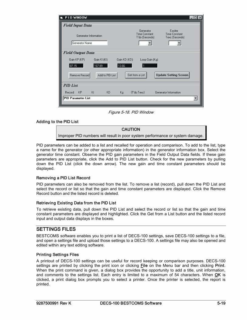
9287500991 Rev K DECS-100 BESTCOMS Software 5-19
Figure 5-18. PID Window
Adding to the PID List
CAUTION Improper PID numbers will result in poor system performance or system damage.
PID parameters can be added to a list and recalled for operation and comparison. To add to the list, type a name for the generator (or other appropriate information) in the generator information box. Select the generator time constant. Observe the PID gain parameters in the Field Output Data fields. If these gain parameters are appropriate, click the Add to PID List button. Check for the new parameters by pulling down the PID List (click the down arrow). The new gain and time constant parameters should be displayed.
Removing a PID List Record PID parameters can also be removed from the list. To remove a list (record), pull down the PID List and select the record or list so that the gain and time constant parameters are displayed. Click the Remove Record button and the listed record is deleted.
Retrieving Existing Data from the PID List To retrieve existing data, pull down the PID List and select the record or list so that the gain and time constant parameters are displayed and highlighted. Click the Get from a List button and the listed record input and output data displays in the boxes.
SETTINGS FILES BESTCOMS software enables you to print a list of DECS-100 settings, save DECS-100 settings to a file, and open a settings file and upload those settings to a DECS-100. A settings file may also be opened and edited within any text editing software.
Printing Settings Files A printout of DECS-100 settings can be useful for record keeping or comparison purposes. DECS-100 settings are printed by clicking the print icon or clicking File on the Menu bar and then clicking Print. When the print command is given, a dialog box provides the opportunity to add a title, unit information, and comments to the settings list. Each entry is limited to a maximum of 54 characters. When OK is clicked, a print dialog box prompts you to select a printer. Once the printer is selected, the report is printed.
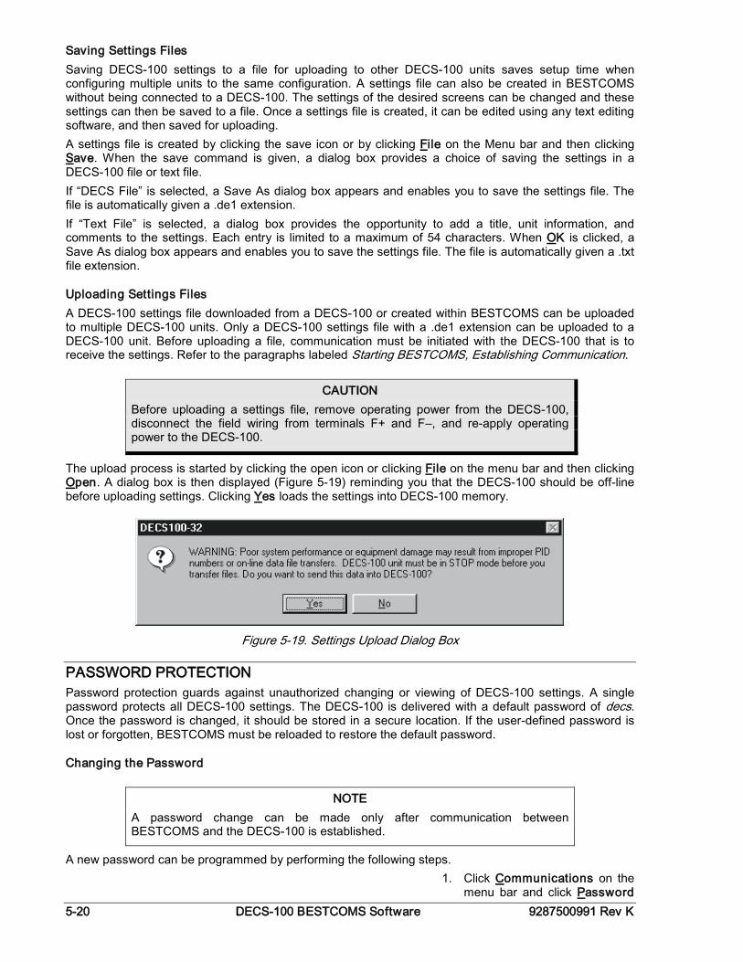
5-20 DECS-100 BESTCOMS Software 9287500991 Rev K
Saving Settings Files Saving DECS-100 settings to a file for uploading to other DECS-100 units saves setup time when configuring multiple units to the same configuration. A settings file can also be created in BESTCOMS without being connected to a DECS-100. The settings of the desired screens can be changed and these settings can then be saved to a file. Once a settings file is created, it can be edited using any text editing software, and then saved for uploading. A settings file is created by clicking the save icon or by clicking File on the Menu bar and then clicking Save. When the save command is given, a dialog box provides a choice of saving the settings in a DECS-100 file or text file. If “DECS File” is selected, a Save As dialog box appears and enables you to save the settings file. The file is automatically given a .de1 extension. If “Text File” is selected, a dialog box provides the opportunity to add a title, unit information, and comments to the settings. Each entry is limited to a maximum of 54 characters. When OK is clicked, a Save As dialog box appears and enables you to save the settings file. The file is automatically given a .txt file extension.
Uploading Settings Files A DECS-100 settings file downloaded from a DECS-100 or created within BESTCOMS can be uploaded to multiple DECS-100 units. Only a DECS-100 settings file with a .de1 extension can be uploaded to a DECS-100 unit. Before uploading a file, communication must be initiated with the DECS-100 that is to receive the settings. Refer to the paragraphs labeled Starting BESTCOMS, Establishing Communication.
The upload process is started by clicking the open icon or clicking File on the menu bar and then clicking Open. A dialog box is then displayed (Figure 5-19) reminding you that the DECS-100 should be off-line before uploading settings. Clicking Yes loads the settings into DECS-100 memory.
Figure 5-19. Settings Upload Dialog Box
PASSWORD PROTECTION Password protection guards against unauthorized changing or viewing of DECS-100 settings. A single password protects all DECS-100 settings. The DECS-100 is delivered with a default password of decs. Once the password is changed, it should be stored in a secure location. If the user-defined password is lost or forgotten, BESTCOMS must be reloaded to restore the default password.
Changing the Password
A new password can be programmed by performing the following steps. 1. Click Communications on the
menu bar and click Password
CAUTION Before uploading a settings file, remove operating power from the DECS-100, disconnect the field wiring from terminals F+ and F–, and re-apply operating power to the DECS-100.
NOTE A password change can be made only after communication between BESTCOMS and the DECS-100 is established.
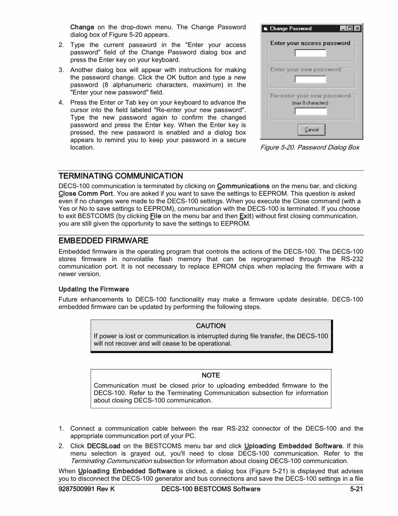
9287500991 Rev K DECS-100 BESTCOMS Software 5-21
Change on the drop-down menu. The Change Password dialog box of Figure 5-20 appears.
2. Type the current password in the "Enter your access password" field of the Change Password dialog box and press the Enter key on your keyboard.
3. Another dialog box will appear with instructions for making the password change. Click the OK button and type a new password (8 alphanumeric characters, maximum) in the "Enter your new password" field.
4. Press the Enter or Tab key on your keyboard to advance the cursor into the field labeled "Re-enter your new password". Type the new password again to confirm the changed password and press the Enter key. When the Enter key is pressed, the new password is enabled and a dialog box appears to remind you to keep your password in a secure location.
Figure 5-20. Password Dialog Box
TERMINATING COMMUNICATION DECS-100 communication is terminated by clicking on Communications on the menu bar, and clicking Close Comm Port. You are asked if you want to save the settings to EEPROM. This question is asked even if no changes were made to the DECS-100 settings. When you execute the Close command (with a Yes or No to save settings to EEPROM), communication with the DECS-100 is terminated. If you choose to exit BESTCOMS (by clicking File on the menu bar and then Exit) without first closing communication, you are still given the opportunity to save the settings to EEPROM.
EMBEDDED FIRMWARE Embedded firmware is the operating program that controls the actions of the DECS-100. The DECS-100 stores firmware in nonvolatile flash memory that can be reprogrammed through the RS-232 communication port. It is not necessary to replace EPROM chips when replacing the firmware with a newer version.
Updating the Firmware Future enhancements to DECS-100 functionality may make a firmware update desirable. DECS-100 embedded firmware can be updated by performing the following steps.
1. Connect a communication cable between the rear RS-232 connector of the DECS-100 and the
appropriate communication port of your PC. 2. Click DECSLoad on the BESTCOMS menu bar and click Uploading Embedded Software. If this
menu selection is grayed out, you'll need to close DECS-100 communication. Refer to the Terminating Communication subsection for information about closing DECS-100 communication.
When Uploading Embedded Software is clicked, a dialog box (Figure 5-21) is displayed that advises you to disconnect the DECS-100 generator and bus connections and save the DECS-100 settings in a file
CAUTION If power is lost or communication is interrupted during file transfer, the DECS-100 will not recover and will cease to be operational.
NOTE Communication must be closed prior to uploading embedded firmware to the DECS-100. Refer to the Terminating Communication subsection for information about closing DECS-100 communication.
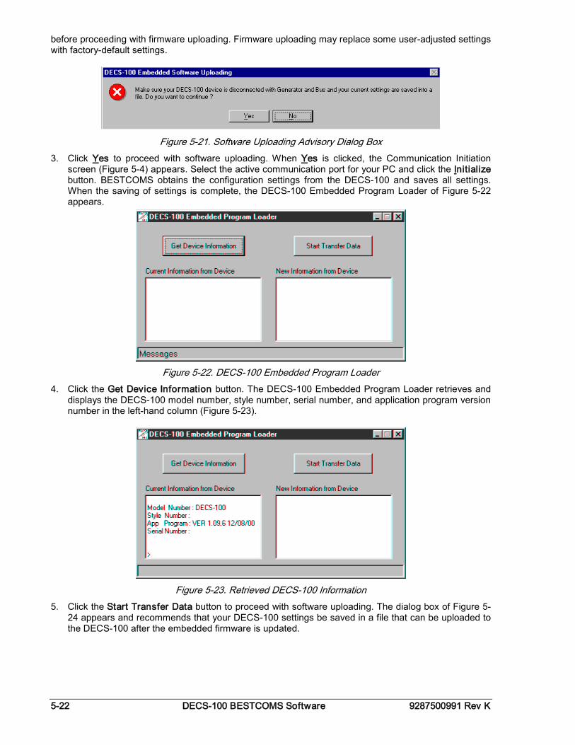
5-22 DECS-100 BESTCOMS Software 9287500991 Rev K
before proceeding with firmware uploading. Firmware uploading may replace some user-adjusted settings with factory-default settings.
Figure 5-21. Software Uploading Advisory Dialog Box
3. Click Yes to proceed with software uploading. When Yes is clicked, the Communication Initiation screen (Figure 5-4) appears. Select the active communication port for your PC and click the Initialize button. BESTCOMS obtains the configuration settings from the DECS-100 and saves all settings. When the saving of settings is complete, the DECS-100 Embedded Program Loader of Figure 5-22 appears.
Figure 5-22. DECS-100 Embedded Program Loader
4. Click the Get Device Information button. The DECS-100 Embedded Program Loader retrieves and displays the DECS-100 model number, style number, serial number, and application program version number in the left-hand column (Figure 5-23).
Figure 5-23. Retrieved DECS-100 Information
5. Click the Start Transfer Data button to proceed with software uploading. The dialog box of Figure 5-24 appears and recommends that your DECS-100 settings be saved in a file that can be uploaded to the DECS-100 after the embedded firmware is updated.
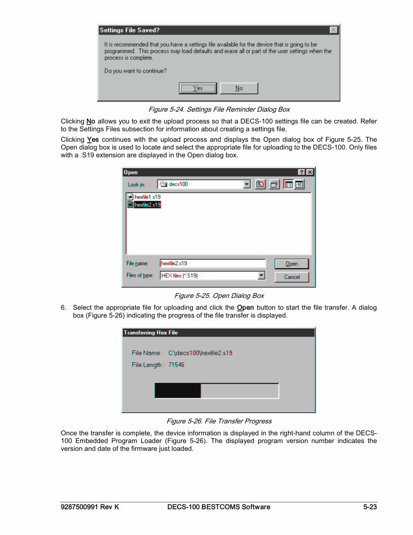
9287500991 Rev K DECS-100 BESTCOMS Software 5-23
Figure 5-24. Settings File Reminder Dialog Box
Clicking No allows you to exit the upload process so that a DECS-100 settings file can be created. Refer to the Settings Files subsection for information about creating a settings file. Clicking Yes continues with the upload process and displays the Open dialog box of Figure 5-25. The Open dialog box is used to locate and select the appropriate file for uploading to the DECS-100. Only files with a .S19 extension are displayed in the Open dialog box.
Figure 5-25. Open Dialog Box
6. Select the appropriate file for uploading and click the Open button to start the file transfer. A dialog box (Figure 5-26) indicating the progress of the file transfer is displayed.
Figure 5-26. File Transfer Progress
Once the transfer is complete, the device information is displayed in the right-hand column of the DECS-100 Embedded Program Loader (Figure 5-26). The displayed program version number indicates the version and date of the firmware just loaded.
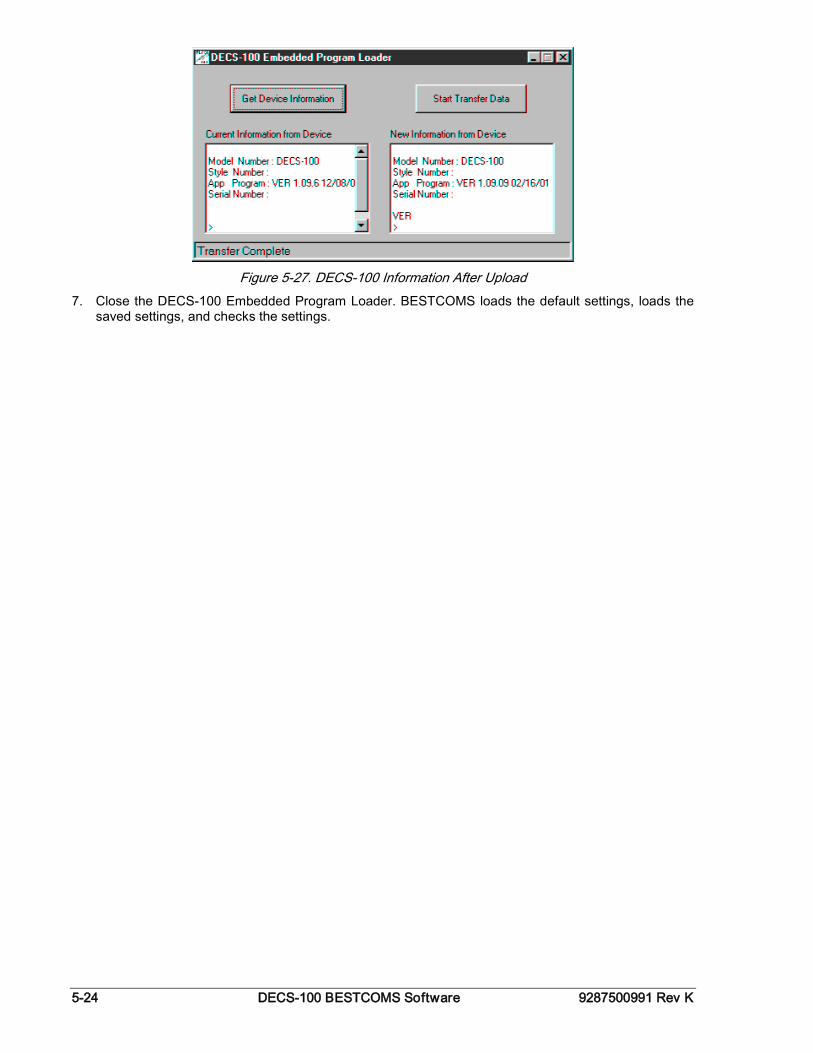
5-24 DECS-100 BESTCOMS Software 9287500991 Rev K
Figure 5-27. DECS-100 Information After Upload
7. Close the DECS-100 Embedded Program Loader. BESTCOMS loads the default settings, loads the saved settings, and checks the settings.
9287500991 Rev K DECS-100 Maintenance and Troubleshooting i
SECTION 6 • MAINTENANCE AND TROUBLE- SHOOTING
TABLE OF CONTENTS SECTION 6 • MAINTENANCE AND TROUBLESHOOTING .................................................................... 6-1
PREVENTATIVE MAINTENANCE ........................................................................................................ 6-1 TROUBLESHOOTING ........................................................................................................................... 6-1
Generator Voltage Does Not Build ..................................................................................................... 6-1 Low Generator Output Voltage........................................................................................................... 6-2 High Generator Output Voltage .......................................................................................................... 6-2 Poor Voltage Regulation .................................................................................................................... 6-4 Generator Output Unstable (Hunting) ................................................................................................ 6-4 Overexcitation Shutdown Indicator is Annunciating ........................................................................... 6-5 Loss of Generator Sensing Indicator is Annunciating ........................................................................ 6-5 Overexcitation Limiting Indicator is Annunciating .............................................................................. 6-5 Underexcitation Limiting Indicator is Annunciating ............................................................................ 6-5 Underfrequency Active Indicator is Annunciating .............................................................................. 6-6 No Droop ............................................................................................................................................ 6-6 No Voltage Matching .......................................................................................................................... 6-7

ii DECS-100 Maintenance and Troubleshooting 9287500991 Rev K
This page intentionally left blank.
9287500991 Rev K DECS-100 Maintenance and Troubleshooting 6-1
SECTION 6 • MAINTENANCE AND TROUBLE-SHOOTING
PREVENTIVE MAINTENANCE The only preventive maintenance required on the DECS-100 is to periodically check that the connections between the DECS-100 and the system are clean and tight. DECS-100 units are manufactured using state-of-the-art, surface-mount technology. As such, Basler Electric recommends that no repair procedures be attempted by anyone other than Basler Electric personnel.
Storage / Electrolytic Capacitors This device contains long-life aluminum electrolytic capacitors. For devices that are not in service (spares in storage), the life of these capacitors can be maximized by energizing the device for 30 minutes once per year.
TROUBLESHOOTING If you do not get the results that you expect from the DECS-100, first check the programmable settings for the appropriate function. Use the following troubleshooting procedures when difficulties are encountered in the operation of your excitation system.
Generator Voltage Does Not Build Step 1. Verify that all wiring is properly connected. Refer to Figures 4-6 through 4-10. If wiring is improperly connected or loose, reconnect wiring properly. If wiring connections are correct, proceed to Step 2. Step 2. Verify that the generator is spinning at rated speed. If the generator is not up to rated speed, increase generator speed to the rated value. If the generator is spinning at rated speed, proceed to Step 3. Step 3. For PMG power, check for correct input power to the DECS-100. Refer to Section 1, General
Information, Specifications for input power requirements. If voltage is not present, refer to the generator manual for repair procedures (PMG system
only). If voltage is present, proceed to Step 4. Step 3a. If the DECS-100 is being shunt powered (non-PMG) mode, verify that the residual voltage
applied to the power input is at least 6 Vac. If the applied voltage is less than 6 Vac, refer to the generator manual and flash the generator
field. If the applied voltage is 6 Vac or greater, proceed to Step 4. Step 4. Verify that no fuses are open. Replace any open fuses. If no fuses are open, proceed to Step 4. Step 5. Verify that the front panel Overexcitation Shutdown indicator is not lit. If the front panel Overexcitation Shutdown indicator (field voltage) is lit, check the generator
and/or load conditions. Interrupt input power or shut down the generator for a minimum of one minute.
If the front panel Overexcitation Shutdown indicator is not lit, proceed to Step 6. Step 6. Verify that the front panel Overexcitation Limiting indicator is not lit. If the front panel Overexcitation Limiting indicator is lit, check the generator and load conditions.
Also check the field current limit setpoint for the correct level. Interrupt input power or shut down the generator for a minimum of 1 minute.
If the front panel Overexcitation Limiting indicator is not lit, proceed to Step 7.
6-2 DECS-100 Maintenance and Troubleshooting 9287500991 Rev K
Step 7. Verify that the DECS-100 soft start settings are correct. Too long of a soft start setting may give the appearance of no buildup.
If the soft start settings are incorrect, adjust the settings. If the soft start settings have no effect, proceed to Step 8. Step 8. Replace the DECS-100 unit. If replacing the DECS-100 unit does not correct the malfunction, then the generator is
defective. Consult with the generator manufacturer.
Low Generator Output Voltage Step 1. Verify that the voltage adjustment is not set too low. If the voltage adjustment is too low, adjust it to the correct setpoint. If the voltage adjustment is correct, proceed to Step 2. Step 2. Verify that the underfrequency knee setpoint is not greater than the generator frequency. If the underfrequency setpoint is too high, adjust the setpoint below the rated generator
frequency. If the underfrequency setpoint is correct, proceed to Step 3. Step 3. Verify that the generator is spinning at rated speed. If the generator is not up to rated speed, increase the generator speed to the rated level. If the generator is spinning at rated speed, proceed to Step 4. Step 4. For PMG power, check for correct input power to the DECS-100. Refer to Section 1, General
Information, Specifications for input power requirements. If the DECS-100 input voltage is low, refer to the PMG manual for PMG repair (PMG system
only). If the voltage is at the required level, proceed to Step 5. Step 4a. If the DECS-100 is being shunt powered (non-PMG), verify that the power potential transformer
(if used) has the correct turns ratio, is sized properly, and is supplying the correct voltage level to the power input.
If the turns ratio of the power potential transformer is incorrect, is sized too small, or is not supplying the correct input power, replace the power potential transformer.
If the power potential transformer is correct, proceed to Step 5. Step 5. Verify that the sensing potential transformer (if used) has the correct turns ratio and is operating
correctly. If the turns ratio of the sensing potential transformer is incorrect, replace the sensing potential
transformer. If the sensing potential transformer is operating correctly, proceed to Step 6. Step 6. Verify that the front panel Overexcitation Limiting indicator is not lit. If the front panel Overexcitation Limiting indicator is lit, check the generator and/or load
conditions. Also check the field-current limit setpoint for the correct level. Interrupt input power or shut down the generator for a minimum of one minute.
If the front panel Overexcitation Limiting indicator is not lit, proceed to Step 7. Step 7. Low generator output voltage may occur when operating in droop mode with an inductive load. If the low voltage condition is not caused by the droop function, proceed to Step 8. Step 8. Verify that the voltage setpoint is not being modified by application of voltage to the optional
Accessory Input. If the low voltage condition is not caused by voltage applied to the Accessory Input, proceed to
Step 9. Step 9. Replace the DECS-100 unit.
High Generator Output Voltage Step 1. Verify that the voltage adjustment is not set too high.
9287500991 Rev K DECS-100 Maintenance and Troubleshooting 6-3
If the voltage adjustment is too high, adjust it to the correct setpoint. If the voltage adjustment is correct, proceed to Step 2.
6-4 DECS-100 Maintenance and Troubleshooting 9287500991 Rev K
Step 2. Verify that the sensing potential transformer (if used) has the correct turns ratio. If the turns ratio of the sensing potential transformer is incorrect, replace the sensing potential
transformer with the correct one. If the sensing potential transformer is correct, proceed to Step 3. Step 3. High generator output voltage may occur when operating in droop mode with a capacitive load. If the high voltage condition is not caused by the droop function, proceed to Step 4. Step 4. Verify that the voltage setpoint is not being modified by application of voltage to the optional
Accessory Input. If the high voltage condition is not caused by voltage applied to the Accessory Input, proceed to
Step 5. Step 5. Replace the DECS-100 unit.
Poor Voltage Regulation Step 1. Verify that the case of the DECS-100 is properly grounded. If the DECS-100 is not properly grounded, connect a dedicated ground wire to the quarter-inch
fast-on connector labeled GND on the rear of the DECS-100 case. If the DECS-100 is properly grounded, proceed to Step 2. Step 2. Check for grounded field leads. If the field leads are grounded, isolate them from ground. If the field leads are not grounded, proceed to Step 3. Step 3. If the DECS-100 is powered from a PMG, check for grounded PMG leads. If the PMG leads are grounded, isolate them from ground. If the PMG leads are not grounded, proceed to Step 4. Step 4. Verify that the generator frequency is not dropping below the DECS-100 underfrequency
setpoint when load is applied to the generator. If the generator frequency is dropping below the underfrequency setpoint, reduce the setpoint if
possible. Also check the prime mover and generator for proper sizing in relation to the applied load.
If poor regulation is not related to DECS-100 underfrequency operation, proceed to Step 5. Step 5. Verify that regulation is not being affected by normal droop operation. If droop operation is not affecting regulation, proceed to Step 6. Step 6. Replace the DECS unit.
Generator Output Unstable (Hunting) Step 1. Verify that the governor for the prime mover is operating properly. If the governor is not operating properly, troubleshoot using the manufacturer's suggested
procedures. If the governor is operating properly, proceed to Step 2. Step 2. Verify that the sensing and input power leads are connected securely. If the sensing or input power leads are not connected securely, tighten the connections. If the sensing or input power lead connections are secure, proceed to Step 3. Step 3. Verify that the DECS-100 Stability Range is set to the proper range. If the Stability Range setting is incorrect, reset the Stability Range. If the Stability Range setting is correct, proceed to Step 4. Step 4. Verify that the Stability Level is properly set. If the Stability Level is not properly set, reset the Stability Level.
9287500991 Rev K DECS-100 Maintenance and Troubleshooting 6-5
Overexcitation Shutdown Indicator is Annunciating Step 1. Check for generator overloading. If the generator is operating with a larger than rated load, shed load. If the generator is operating with a rated or less than rated load, proceed to Step 2. Step 2. Verify that the generator exciter field voltage requirements are compatible with the DECS-100. If the exciter field voltage requirements are not compatible with the DECS-100, contact Basler
Electric Customer Service for recommendations. If the exciter field voltage requirements are compatible with the DECS-100, proceed to Step 3. Step 3. Replace the DECS-100. If replacing the DECS-100 does not correct the malfunction, proceed to Step 4. Step 4. Refer to the generator manual. Generator is defective.
Loss of Generator Sensing Indicator is Annunciating Step 1. Verify that the voltage sensing leads are properly connected. If the sensing leads are not properly connected, correct the connections. If the sensing lead connections are correct, proceed to Step 2. Step 2. For single-phase sensing, verify that E2 and E3 are connected. If E2 and E3 are not connected, connect them both to phase C sensing voltage. If E2 and E3 are properly connected, proceed to Step 3. Step 3. Verify that the sensing potential transformer (if used) has the correct turns ratio and is
functioning properly. If the sensing potential transformer has the wrong turns ratio or is malfunctioning, replace it. If the sensing potential transformer is correct and functioning properly, proceed to Step 4. Step 4. Verify that the generator output voltage is present on all phases. If the generator is missing a phase, refer to the generator manual. Generator is defective. If generator output voltage is balanced on all phases, proceed to Step 5. Step 5 Replace the DECS-100.
Overexcitation Limiting Indicator is Annunciating Step 1. Check for generator overloading. If the generator is operating with a larger than rated load, shed load. If the generator is operating with a rated or less than rated load, proceed to Step 2. Step 2. Verify that the DECS-100 output (field) current limit is not set too low. If the output current limit setpoint is too low, adjust for the proper setting. If the output current limit is set properly, proceed to Step 3. Step 3. Verify that the generator exciter field current requirements are compatible with the DECS-100. If the generator exciter field current requirements are not compatible with the DECS-100,
contact Basler Electric Customer Service for recommendations. If the generator exciter field current requirements are compatible with the DECS-100, proceed
to Step 4. Step 4. Replace the DECS-100. If replacing the DECS-100 does not correct the malfunction, proceed to Step 5. Step 5. Refer to the generator manual. Generator is defective.
Underexcitation Limiting Indicator is Annunciating Step 1. Verify that the DECS-100 generator voltage setpoint is not being driven to a lower level. The setpoint can be affected by the Raise/Lower contact inputs or by the Auxiliary input.
6-6 DECS-100 Maintenance and Troubleshooting 9287500991 Rev K
Step 2. Verify that the DECS-100 output (field) current limit is not set too low. Adjust the field current limit as needed. Step 3. Use the connection diagrams of Section 4, Installation to verify that the sensing voltage and
current connections to the DECS-100 provide the proper phasing. Correct the sensing voltage and current connections as needed. Step 4. Verify that the generator exciter field current requirements are compatible with the DECS-100. If the generator exciter field current requirements are not compatible with the DECS-100,
contact Basler Electric Technical Sales Support for recommendations. If the generator exciter field current requirements are compatible with the DECS-100, proceed
to Step 5. Step 5. Replace the DECS-100. If replacing the DECS-100 does not correct the malfunction, proceed to Step 6. Step 6. Refer to the generator manual or contact the generator manufacturer.
Underfrequency Active Indicator is Annunciating Step 1. Verify that the generator is operating at rated speed. If the generator is not operating at rated speed, adjust the generator speed. If the generator is operating at the rated speed, proceed to Step 2. Step 2. Verify that the underfrequency setpoint is correct. If the underfrequency setpoint is incorrect, adjust it to the correct value.
No Droop Step 1. Verify that the DECS-100 52L/M contact input is open. If the 52L/M contact input is not open, it must be opened to enable the droop function. If the 52L/M contact input is open, proceed to Step 2. Step 2. Verify that the DECS-100 52J/K contact input (if present) is closed or the Var/PF function is
disabled via BESTCOMS. Var/PF operation must be disabled for droop operation. If var/PF operation is disabled, proceed to Step 3.
Step 3. Verify that the DECS-100 droop setting is not adjusted to 0% droop. If the droop setting is adjusted to 0% droop, increase the setpoint above 0%. If the droop setting is adjusted to above 0%, proceed to Step 4. Step 4. Check for an open in the circuit connected to DECS-100 CT1 and CT2. If there is an open circuit, repair as necessary. If there is no open circuit, proceed to Step 5. Step 5. Verify that all connections are correct according to Figures 4-6 through 4-9. If connections are incorrect, correct the problem. If connections are correct, proceed to Step 6. Step 6. Verify that the load being applied to the generator for droop testing is not purely resistive. If only a resistive load is being applied to the generator, apply an inductive load and retest. If the load being applied to the generator is inductive, proceed to Step 7. Step 7. Verify that your DECS-100 is compatible with the current sensing transformer (1 A or 5 A
secondary) being used. For example, a current sensing transformer with a 1 ampere output rating would produce very little droop if your DECS-100 has a 5 ampere current transformer input. Refer to Figure 1-1 to check the current transformer input of your DECS-100.
If the current transformer input is incorrect, replace the current sensing transformer or the DECS-100 for compatibility.
If the current transformer input is correct, proceed to Step 8. Step 8. If the above steps fail to correct the malfunction, replace the DECS-100 unit.
9287500991 Rev K DECS-100 Maintenance and Troubleshooting 6-7
No Voltage Matching Step 1. Verify that the Voltage Matching option was purchased and is enabled in the software. If not enabled, use the BESTCOMS software to turn on voltage matching. If voltage matching is enabled, proceed to Step 2. Step 2. Verify that all connections are correct according to Figures 4-6 through 4-9 as required for the
Voltage Matching option of the DECS-100. If the interconnection is incorrect, reconnect according to the appropriate interconnect diagram. If the interconnection is correct, proceed to Step 3. Step 3. Verify that the DECS-100 VM/VMC contact input is closed. If the VM/VMC contact input is open, it must be closed to enable voltage matching. If the VM/VMC contact input is closed, proceed to Step 2. Step 4. Check for correct utility reference voltage on DECS-100 terminals B1 and B3. If the interconnection is incorrect, reconnect according to the appropriate interconnect diagram. If the interconnection is correct, check for open system fuses. Verify that the potential sensing transformer, if used, is connected to DECS-100 terminals B1
and B3. If potential sensing transformer connections are correct, proceed to Step 5. Step 5. Verify that the generator output voltage setpoint is within 10 percent of the measured utility bus
voltage. If the setpoint is too low or too high, adjust the setpoint to the appropriate level. If the setpoint is correct, proceed to Step 6. Step 6. If the above steps fail to correct the Voltage Matching malfunction, replace the DECS-100.