Embed Size (px)
Citation preview

DECS-200 Digital Excitation Control System
SZM-10 9-09
One DECS-200 Digital Excitation Control System can accommodate 32Vdc, 63Vdc, or125Vdc applications up to 15Adc. This unique flexibility provides precision control ofgenerators of virtually any size. The DECS-200 also incorporates a pulse width modulatedpower stage, which improves system performances in non-linear load applications.
DECS-200Digital ExcitationControl System
P. O. BOX 269 HIGHLAND, ILLINOIS, U.S.A. 62249 PHONE 618-654-2341 FAX 618-654-2351
DESCRIPTION andSPECIFICATIONSPages 2 through 5
FEATURES andFUNCTIONSPages 6 and 7
INTERCONNECTDIAGRAM
Page 8
FRONT, SIDE VIEWSand DIMENSIONSPages 9 through 11
ORDERINGPage 12
FEATURES
ADDITIONAL INFORMATIONINSTRUCTION MANUAL
Request Publication 9360100990
WINDOWS® SOFTWAREInterface for setting and communicating with Basler products
Request DECS-200-CD
• Microprocessor-based design• True RMS sensing, single or three phase• 32Vdc, 63Vdc, and 125Vdc outputs at 15Adc• 0.25% Voltage Regulation Accuracy• Setup from front panel HMI or by PC with Windows® setup software included• 20 standard stability selections• User customizable stability selection• Paralleling compensation• Underfrequency compensation or V/Hz Ratio Limiter• Soft start buildup• Field Current Regulation Mode (Manual Mode)• Autotracking between operating modes and between DECS-200 units
(optional)• Minimum Excitation Limiter (Internally generated or customizable)• On and off-line Maximum Excitation Limiters• Stator Current Limiter• Var and Power Factor Controllers• Exciter Diode Monitoring (EDM)• Sequence of Events Recording• Oscillography (continued on next page)

DECS-200 Digital Excitation Control System
2
FEATURES, continued
DESCRIPTION
INPUTSControl Power (style selectable)
16-60Vdc, Burden=30W. 85-132Vac, 50 or 60Hz, Burden=50VA. 90-150Vdc, Burden=30W.
AC Operating Power1 or 3 Phase Power Input
DECS-200 Output AC Voltage Nominal Range (50-500Hz) Burden32Vdc 60Vac 56-70Vac ±10% 780VA63Vdc 120Vac 100-139Vac ±10% 1570VA125Vdc 240Vac 190-277Vac ±10% 3070VA
NOTES:1)For applications that require the DECS-200 from a source that is already at the regulator's rated power input voltage level, an Inrush
Current Reduction Module is needed to minimize the amount of inrush current that may occur. Refer to Accessories (see page 11),regarding ICRM-15.
2)To achieve the proper DECS-200 output voltage, the associated Operating Power must be provided. Min. voltage buildup: 3 Vac.
Generator Voltage Sensing Single-phase or three-phase line voltage, four ranges:• 100V/50Hz nominal (85 to 127V), 120V/60Hz nominal (94 to 153V)• 200V/50Hz nominal (170 to 254V), 240V/60Hz nominal (187 to 305V)• 400V/50Hz nominal (340 to 508V), 400V/60Hz nominal (374 to 600V)• 500V/50Hz nominal (425 to 625V), 600V/60Hz nominal (510 to 660V)
Bus Voltage Sensing Single-phase line voltage (AC), four ranges:• 100V/50Hz nominal (85 to 127V), 120V/60Hz nominal (94 to 153V)• 200V/50Hz nominal (170 to 254V), 240V/60Hz nominal (187 to 305V)• 400V/50Hz nominal (340 to 508V), 400V/60Hz nominal (374 to 600V)• 500V/50Hz nominal (425 to 625V), 600V/60Hz nominal (510 to 660V)
SPECIFICATIONS
The microprocessor based DECS-200 is a total excita-tion control system in one enclosure. It contains all thefunctionality necessary to limit, control, and protect agenerator from operating outside of the machine'scapability. An optional feature of DECS-200's sophisti-cated design allows the nonactive control mode withinthe unit to follow the active mode, permitting bumplesstransfer between modes. The optional software alsoallows for unit-to-unit communication, permitting
autofollowing and transfer between DECS-200 units. Itcan also communicate to a PC via the front panel RS-232 port for local programming and metering, and itcan communicate via Modbus™ protocol via the sideRS-485 port for communications up to 4000 feet awayfrom the DECS-200 unit. The DECS-200 has all thefeatures, functionality, flexibility and programmabilityexpected from a state-of-the-art microprocessor basedproduct.
• Voltage Matching• Eight (8) generator protection features• Programmable output contacts• Front panel backlit LCD display• Front panel mounted RS-232 and side RS-485
communications ports• Modbus™ protocol for RS-485 input allows
communications up to 4000 feet away• <1% metering accuracy for 12 generator parameters
• Remote set point control via:- Contact inputs- Proportional control via ±10Vdc or 4-20mA- Communications inputs RS-232 (ASCII) or RS-485 (Modbus™)
• Meets C37.90.1-1989 for Surge Withstand and FastTransient
• UL recognized, CSA certified, CE compliant, DNVcertified, GOST-R certified, Byelorussian certified
• U.S. Patent Number 5,294,879
APPLICATIONSThe DECS-200 is an excitation control system used to control the output voltage, vars or power factor of a syn-chronous generator by varying or controlling the amount of dc excitation applied to the generator's exciter field.The DECS-200 is suitable for virtually any size machine.
DECS-200 Digital Excitation Control System
3
SPECIFICATIONS, continued
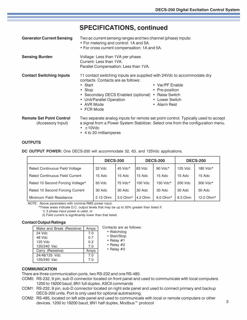
Generator Current Sensing Two ac current sensing ranges and two channel (phase) inputs:• For metering and control: 1A and 5A.• For cross current compensation: 1A and 5A.
Sensing Burden Voltage: Less than 1VA per phase.Current: Less than 1VA.Parallel Compensation: Less than 1VA.
Contact Switching Inputs 11 contact switching inputs are supplied with 24Vdc to accommodate drycontacts. Contacts are as follows:• Start • Var/PF Enable• Stop • Pre-position• Secondary DECS Enabled (optional) • Raise Switch• Unit/Parallel Operation • Lower Switch• AVR Mode • Alarm Rest• FCR Mode
Remote Set Point Control Two separate analog inputs for remote set point control. Typically used to accept(Accessory Input) a signal from a Power System Stabilizer. Select one from the configuration menu.
• ±10Vdc• 4 to 20 milliamperes
OUTPUTS
DC OUTPUT POWER: One DECS-200 will accommodate 32, 63, and 125Vdc applications.
Contact Output Ratings
Make and Break (Resistive) Amps
24 Vdc 7.048 Vdc 0.7125 Vdc 0.2120/240 Vac 7.0Carry (Resistive) Amps
24/48/125 Vdc 7.0120/240 Vac 7.0
COMMUNICATIONThere are three communication ports, two RS-232 and one RS-485:COM0: RS-232, 9 pin, sub-D connector located on front panel and used to communicate with local computers.
1200 to 19200 baud, 8N1 full duplex, ASCII commandsCOM1: RS-232, 9 pin, sub-D connector located on right side panel and used to connect primary and backup
DECS-200 units. Port is only used for optional autotracking.COM2: RS-485, located on left side panel and used to communicate with local or remote computers or other
devices. 1200 to 19200 baud, 8N1 half duplex, Modbus™ protocol
DECS-200 DECS-200 DECS-200
Rated Continuous Field Voltage 32 Vdc 45 Vdc* 63 Vdc 90 Vdc* 125 Vdc 180 Vdc*
Rated Continuous Field Current 15 Adc 15 Adc 15 Adc 15 Adc 15 Adc 15 Adc
Rated 10 Second Forcing Voltage* 50 Vdc 75 Vdc* 100 Vdc 150 Vdc* 200 Vdc 300 Vdc*
Rated 10 Second Forcing Current 30 Adc 30 Adc 30 Adc 30 Adc 30 Adc 30 Adc
Minimum Field Resistance 2.13 Ohm 3.0 Ohm* 4.2 Ohm 6.0 Ohm* 8.3 Ohm 12.0 Ohm*
NOTE: Above parameters with nominal RMS power input. *These areas indicate D.C. output levels that may be up to 50% greater than listed if:
1) 3 phase input power is used, or 2) Field current is significantly lower than that listed.
Contacts are as follows:• Watchdog• Start/Stop• Relay #1• Relay #2• Relay #3

DECS-200 Digital Excitation Control System
4
SPECIFICATIONS, continued
REGULATION ACCURACYAVR Mode: Voltage regulation equals ±0.25% over the load range at rated power factor and constantgenerator frequency. Steady state stability equals ±0.1% at a constant load and generator frequency.Temperature drift equals ±0.5% for 0 to 50°C temperature change. Underfrequency (volts/hertz) characteristicslope from 0 to 3.0 P.U. is adjustable in 0.1 P.U. increments.
FCR Mode: Field current regulation equals ±1.0% of the nominal value for 10% of the bridge input voltagechange or 20% of the field resistance change.
var Mode: ±2.0% of the nominal VA rating at the rated frequency.
PF Mode: ±0.02 PF in the set point PF for the real power between 10 and 100% at the rated frequency.(e.g. -set point PF=0.80, PF regulation is from 0.78 to 0.82 PF.)
Internal autotracking(optional): ±0.5% of the nominal field voltage change when transferring.
PARALLEL COMPENSATION Can use either reactive droop or reactive differential (cross-current) compen-sation. Adjustable from 0 to 30% of the rated generator voltage droop with optional 1 ampere or less or 5 amperesor less input. Line drop compensation uses this same parameter; however, it is adjustable from -30% to 0.
FIELD OVERVOLTAGE PROTECTION Adjustable in increments of 1.0Vdc from 1.0 to 325Vdc rated outputvoltage with a 0.2 to a 0.2 to 30 second inverse time delay settable in increments of 0.1 second.
FIELD OVERCURRENT PROTECTION Adjustable in increments of 0.1Adc steps of rated field current from 0 to16Adc excitation current setting with an inverse time delay (ANSI C50.13).
EXCITER DIODE MONITOR (EDM) The DECS-200's EDM can detect open and shorted diodes on brushlessgenerators. To do this, the DECS-200 requires the user to input the number of generator poles and the number ofexciter poles (both adjustable from 0 to 20 in increments of 2). The open and shorted diode ripple threshold isadjustable from 0 to 100% of field current. The open diode protection time delay is adjustable from 10 to 60seconds, and the shorted diode protection time delay is adjustable from 5 to 30 seconds.
GENERATOR UNDERVOLTAGE PROTECTION Adjustable in increments of 1Vac from 0 to 30kV sensing voltagesetting with a 0.5 to 60 second time delay (ANSI C50.13) settable in increments of 0.1 sec.
GENERATOR OVERVOLTAGE PROTECTION Adjustable in increments of 1Vac from 0 to 30kV sensing voltagewith a 0.1 to 60 second time delay (ANSI C50.13) settable in increments of 0.1 second.
GENERATOR LOSS OF FIELD PROTECTION Adjustable in increments of 1 kVar from 0 to 3,000Mvar, with a 0.1to 9.9 second delay settable in increments of 0.1 second.
LOSS OF SENSING The loss of sensing setting for both balanced and unbalanced generator voltage is adjust-able from 0 to 100% of nominal generator voltage. The protection delay is adjustable from 0 to 30 seconds in 0.1increments.
SOFT START Functional in AVR and FCR with an adjustable rate of 1 to 7200 seconds in one second increments.
SUMMING POINT and TAKEOVER TYPEOVEREXCITATION LIMITING Limiter response time is less than three cycles.
SUMMING POINT TYPE:On-Line High Current Level (instantaneous) set point adjustable from 0 to 30.0Adc in 0.1Adc incre-
ments. Limiting occurs for a time period ranging from 0 to 10 sec., settable in 1 sec. increments.Medium Current Level set point adjustable from 0 to 20Adc in 0.1Adc increments.Limiting occurs for a time period ranging from 0 to 120 seconds, settable in 1 sec. increments.Low Current Level set point adjustable from 0 to 15Adc in 0.1Adc increments. Limiting occursindefinitely.
DECS-200 Digital Excitation Control System
5
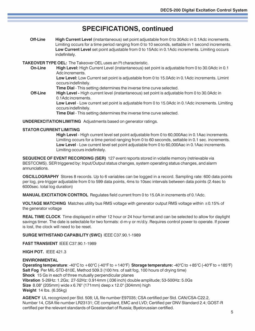
Off-Line High Current Level (instantaneous) set point adjustable from 0 to 30Adc in 0.1Adc increments.Limiting occurs for a time period ranging from 0 to 10 seconds, settable in 1 second increments.Low Current Level set point adjustable from 0 to 15Adc in 0.1Adc increments. Limiting occursindefinitely.
TAKEOVER TYPE OEL: The Takeover OEL uses an I2t characteristic.On-Line High Level: High Current Level (instantaneous) set point is adjustable from 0 to 30.0Adc in 0.1
Adc increments.Low Level: Low Current set point is adjustable from 0 to 15.0Adc in 0.1Adc increments. Limintoccurs indefinitely.Time Dial - This setting determines the inverse time curve selected.
Off-Line High Level - High current level (instantaneous) set point is adjustable from 0 to 30.0Adc in0.1Adc increments.Low Level - Low current set point is adjustable from 0 to 15.0Adc in 0.1Adc increments. Limitingoccurs indefinitely.Time Dial - This setting determines the inverse time curve selected.
UNDEREXCITATION LIMITING Adjustments based on generator ratings.
STATOR CURRENT LIMITINGHigh Level - High current level set point adjustable from 0 to 60,000Aac in 0.1Aac increments.Limiting occurs for a time period ranging from 0 to 60 seconds, settable in 0.1 sec. increments.Low Level - Low current level set point adjustable from 0 to 60,000Aac in 0.1Aac increments.Limiting occurs indefinitely.
SEQUENCE OF EVENT RECORDING (SER) 127 event reports stored in volatile memory (retrievable viaBESTCOMS). SER triggered by: Input/Output status changes, system operating status changes, and alarmannunciations.
OSCILLOGRAPHY Stores 8 records. Up to 6 variables can be logged in a record. Sampling rate: 600 data pointsper log, pre-trigger adjustable from 0 to 599 data points, 4ms to 10sec intervals between data points (2.4sec to6000sec. total log duration)
MANUAL EXCITATION CONTROL Regulates field current from 0 to 15.0A in increments of 0.1Adc.
VOLTAGE MATCHING Matches utility bus RMS voltage with generator output RMS voltage within ±0.15% ofthe generator voltage
REAL TIME CLOCK Time displayed in either 12 hour or 24 hour format and can be selected to allow for daylightsavings timer. The date is selectable for two formats: d-m-y or m/d/y. Requires control power to operate. If poweris lost, the clock will need to be reset.
SURGE WITHSTAND CAPABILITY (SWC) IEEE C37.90.1-1989
FAST TRANSIENT IEEE C37.90.1-1989
HIGH POT. IEEE 421.3
ENVIRONMENTALOperating temperature: -40°C to +60°C (-40°F to +140°F) Storage temperature: -40°C to +85°C (-40°F to +185°F)Salt Fog Per MIL-STD-810E, Method 509.3 (100 hrs. of salt fog, 100 hours of drying time)Shock 15 Gs in each of three mutually perpendicular planesVibration 5-26Hz: 1.2Gs; 27-52Hz: 0.914mm (.036 inch) double amplitude; 53-500Hz: 5.0GsSize 8.08" (205mm) wide x 6.76" (171mm) deep x 12.0" (304mm) highWeight 14 lbs. (6.35kg)
AGENCY UL recognized per Std. 508; UL file number E97035; CSA certified per Std. CAN/CSA-C22.2,Number 14, CSA file number LR23131; CE compliant, EMC and LVD; Certified per DNV Standard 2.4; GOST-Rcertified per the relevant standards of Gosstandart of Russia; Byelorussian certified.
SPECIFICATIONS, continued

DECS-200 Digital Excitation Control System
6
FEATURES/FUNCTIONS
Voltage RegulationThe DECS-200 regulates the generator RMS voltage to within0.25% from no-load to full-load. It does this by utilizing digital signalprocessing and precise regulation algorithms developed by BaslerElectric, utilizing the experience gained in many years of manufac-
turing tens of thousands of digital voltage regulators.
StabilityThe DECS-200 utilizes proportional (P), integral (I) and derivative(D) stability control. DECS-200 has 20 preprogrammed stability(PID) settings for exciter field applications. This means that astandard stability setting is already available for most applications/machines. The DECS-200 has a stability range that allows forcustomizing the stability settings to fine tune the stability to provideoptimum customized generator transient performance. Setupsoftware contains PID selection program to assist in determiningthe correct PID settings. The DECS-200 provides for customizingthe stability and transient performance of the Min/Max ExcitationLimiter and var/PF controllers by providing additional stability
adjustments.
Underfrequency Limiter or V/Hz Ratio LimiterDECS-200 is selectable for either Underfrequency Limiter or aV/Hz Ratio Limiter function. The underfrequency limiter slope canbe tuned to have 0 to 3 times p.u. Volts/Hz, in 0.1Hz increments,and the corner frequency roll-off point can be set across a rangeof 45 to 65Hz, in 0.1Hz increments. This adjustability allows theDECS-200 to precisely match the operating characteristics of theprime mover and the loads being applied to the generator. TheVolts/Hz Ratio Limiter clamps the regulation set point to preventoperation above a V/Hz level that is prescribed by the slope of theDECS-200. This feature is also useful for other potentially damagingsystem conditions such as a change in system voltage and re-
duced frequency situations that exceed the V/Hz ratio.
Soft Start Voltage BuildupGenerator voltage overshoot can be harmful to the generator'sinsulation system if not controlled. DECS-200 has a soft start featurewith a user-adjustable setting to govern the rate at which thegenerator voltage is allowed to build up. This prevents thegenerator voltage from overshooting nominal voltage levels during
startup of the generator system.
Paralleling CompensationDECS-200 has provisions to parallel two or more generators usingreactive droop or reactive differential compensation with theaddition of an external current transformer with secondary currentsof 1 or 5Aac. The current input is rated at less than 1VA. This lowburden means that existing metering CTs can be used and
dedicated CTs are not required.
Set Point ControlDECS-200 has means for external set point adjustment of thecontrolling mode of operation. This eliminates the need foradditional equipment like motor operated potentiometers forremote control or multiple point control for the excitation system.The operating mode's set point may be directly controlled by raise/lower contact inputs, auxiliary inputs of 4-20mA or ±10Vdc. Theauxiliary input adjusts the operating mode across its predeter-mined adjustment range. The auxiliary input can be provided from
other controlling devices such as a power system stabilizer.These devices modify the operation of the DECS-200 to meetspecific operating characteristics and requirements for the machineunder DECS-200 control. Two more methods of set point controlmay be achieved via the RS-232 communication port by using theWindows® based PC software or by the RS-485 port usingModbus™ protocol. Regardless of which method of set point isused (contact inputs, auxiliary input or communications with a PC orPLC), traverse rates of all modes of operation are independentlyadjustable. This means an operator can customize the rate of
adjustment and "feel" to meet his/her needs.
Pre-position InputsDECS-200 provides the added flexibility of allowing a predeter-mined operating point for each mode of operation. With a contactinput to the DECS-200, the operating mode is driven to anoperating or regulation level assigned to that operation mode bythe operator or user. The pre-position inputs operate in one of twomodes, Maintain or Release. The Maintain mode prevents adjust-ment of the setpoint as long as the pre-position contact is closed.The release mode allows adjustment of the setpoint even though thepre-position is closed. This feature allows the DECS-200 to be
configured for specific system and application needs.
Field Current Regulation Operating ModeDECS-200 provides a manual channel of operation called FieldCurrent Regulation, or FCR, Mode. In this mode, DECS-200regulates the field current generated by the internal PWM powerstage. It does not rely on the sensing input to DECS-200 and is,therefore, a good source of backup excitation control when loss ofsensing is detected. In this mode, control of the generator is totallydependent upon the operator to maintain nominal generatorvoltage as the load varies on the generator.
Var/Power Factor Controller Operating ModeDECS-200 has, as another standard feature, two modes ofoperation when the generator is in parallel with the utility powergrid. The DECS-200 has both var and PF modes of operation.When the generator is in parallel with the utility grid, the DECS-200can regulate the var output of the generator to a specific var levelmagnitude or it can vary the var output of the generator to maintaina specific power factor as the kW load varies on the generator.
Maximum Excitation LimitersOverexcitation limiting (OEL) operates in all modes except FCRmode. OEL senses the field current output of the voltage regulatoror static exciter and limits the field current to prevent field overheat-ing. In FCR mode, the DECS-200 only announces that all conditionsfor OEL are fulfilled and does not provide limiting. The DECS-200
provides two types of overexcitation: Summing Point and Takeover.
Summing Point Type OELThree OEL current levels are defined for on-line operation. They arehigh, medium, and low. The generator can operate continuously atthe low OEL current level and for programmed times at the highand medium OEL current levels. Two OEL current levels aredefined for off-line (main breaker open) operation. They are highand low. The generator can operate continuously at the low OELcurrent level and for a programmed time at the high OEL currentlevel.

DECS-200 Digital Excitation Control System
FEATURES/FUNCTIONS, continued
Takeover Type OELThe field current level at which limiting occurs is determined by aninverse time characteristic. Two current levels and a time dial settingare defined for the takeover-style OEL limiter. Separate curves maybe selected for on-line and off-line operation. If the system enters anoverexcitation condition, the field current is limited and made tofollow the selected curve. The selection of on-line or off-line OEL
levels/curves is determined by an OEL option selection.
Minimum Excitation LimiterThe minimum excitation limiter limits the amount of excitationsupplied to the field of the generator from dropping below unsafeoperating levels. This prevents the machine from possibly slippingpoles and from damaging the machine. It limits the amount of varsbeing absorbed by the machine, based on user-definable settings.An internally generated Underexcitation Limiting (UEL) curve canbe utilized based on a var level at 0kW, or a customizable 5 pointUEL curve can be selected to match specific generator characteris-
tics.
Stator Current LimiterThe stator current limiter (SCL) senses the level of stator currentand limits it to prevent stator overheating. The SCL operates in allmodes except FCR. In FCR mode, the DECS-200 only announcesthat a stator overcurrent condition exists; it does not provide currentlimiting. Two SCL current levels are provided: high and low. Thegenerator can operate continuously at the low SCL level but only for
a programmed time at the high SCL level.
Internal Autotracking Between DECS-200 OperatingModesDECS-200 is an intelligent device that can provide autotracking(autofollowing) of the controlling mode by the non-controllingmodes. This allows the operator to initiate a controlled, bumplesstransfer of the DECS-200 operating modes, causing minimumamounts of line disturbance for the power system. This feature canbe used in conjunction with a set of protective relays to initiate atransfer to a backup mode of operation, such as FCR mode, upon
the detection of a system failure or fault, i.e., loss of sensing.
External Autotracking between Dual DECS-200 Units
(Optional)A DECS-200 can also follow (autotrack) a second DECS-200 unit.The second DECS-200 is put into a specific operating mode andfollows the excitation level of the first. In the unlikely event of a failureof the first DECS-200, protective relays can initiate a transfer of
control from the first to the second DECS-200.
Protective FunctionsThere are several protection functions built into the DECS-200 unit.These functions may be used as backup to the primary protectionrelays and can be assigned programmable output contacts via thePC software. The protection features offer fully adjustable trippinglevels and time delays. The protective features are as follows:
• Generator Overvoltage • Watchdog Timer• Generator Undervoltage • Loss of Sensing• Field Overvoltage • Loss of field
• Field Overcurrent • EDM Exciter Diode Monitor
Sequence of Events Recording (SER)A sequence of event report (SER) is a very powerful tool whenreconstructing the exact timing of an event or disturbance. TheDECS-200 monitors its contact inputs and outputs for a change ofstate, system operation changes, and alarm conditions. If any ofthese events occurs, the DECS-200 will log that event with a dateand time stamp. Date and time stamping of the event allows theuser to recreate a chain of events in the sequence in which theyoccurred. The DECS-200 can store 127 events in volatile memory,
and those events are retrievable using BESTCOMS.
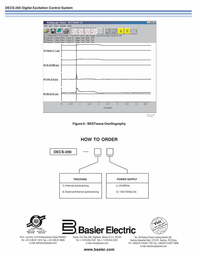
Oscillography (See Figure 6)The data recording feature can record up to eight (8) oscillo-graphic records stored in volatile memory. The user can select upto six (6) variables to be monitored when triggered by the DECS-200 BESTCOMS, a Logic Trigger, or a Level Trigger. Variables thatcan be selected are: generator voltage, current (single phase),frequency, kW, Power Factor, exciter field voltage, and current.
The user can utilize the DECS-200 BESTCOMS to trigger and savea record of a voltage step response during commissioning. Oncecommissioned, a logic trigger or level trigger can be used toactivate the data recorder to capture the occurrence for review at alater time. DECS-200 alarms can also be used to start the datarecorder. When an alarm condition occurs, an oscillographicrecord can be stored. A level trigger will initiate a record to besaved when a variable exceeds a predetermined setting. Anexample of this is when the exciter field current exceeds a predeter-mined setting.
The oscillographic records are recorded in accordance with theIEEE Standard Common Format for Transient Data Exchange(COMTRADE). Basler Electric can provide BESTWAVE, aCOMTRADE viewer, which is a program that will allow the user toview the oscillography records saved by the DECS-200.
CommunicationsDECS-200 comes complete with Windows® based PC software.This software makes the programming and customization of theDECS-200 easy and fast. The software comes with a PID selectionprogram that allows the user to select stability settings quickly andeasily in a user-friendly format. The PC software has a specialmonitoring function that allows the user to view all settings, ametering screen for viewing all machine parameters, and a controlscreen for remote control of the excitation system.
The RS-485 port supports Modbus™ communications protocol. Thisis an open protocol with all registers and operating instructionsavailable in the instruction manual, to make it simple for the user to
develop custom communications software.
Password ProtectionAll DECS-200 parameters are viewable via the front panel LCDdisplay, the PC software or via Modbus™ without the need of apassword. If the user wishes to change a setting, the properpassword must be entered to allow access to the parameter. Twolevels of password protection exist, one for global access of allparameters and one for a limited amount of access to parameters
normally associated with operator control.
7

DECS-200 Digital Excitation Control System
8
CONNECTIONS
Figure 1 - Typical AC Connection Diagram
DECS-200 Digital Excitation Control System
9
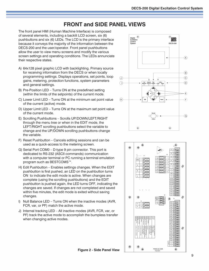
The front panel HMI (Human Machine Interface) is composedof several elements, including a backlit LCD screen, six (6)pushbuttons and six (6) LEDs. The LCD is the primary interfacebecause it conveys the majority of the information between theDECS-200 and the user/operator. Front panel pushbuttonsallow the user to view menu screens and modify the variousscreen settings and operating conditions. The LEDs annunciatetheir respective states.
A) 64x128 pixel graphic LCD with backlighting. Primary sourcefor receiving information from the DECS or when locallyprogramming settings. Displays operations, set points, loopgains, metering, protection functions, system parametersand general settings.
B) Pre-Position LED – Turns ON at the predefined setting(within the limits of the setpoints) of the current mode.
C) Lower Limit LED – Turns ON at the minimum set point valueof the current (active) mode.
D) Upper Limit LED – Turns ON at the maximum set point valueof the current mode.
E) Scrolling Pushbuttons – Scrolls UP/DOWN/LEFT/RIGHTthrough the menu tree or when in the EDIT mode, theLEFT/RIGHT scrolling pushbuttons select the variable tochange and the UP/DOWN scrolling pushbuttons changethe variable.
F) Reset Pushbutton – Cancels editing sessions and can beused as a quick-access to the metering screen.
G) Serial Port COM0 – D-type 9 pin connector. This port isdedicated to RS-232 (ASCII commands) communicationwith a computer terminal or PC running a terminal emulationprogram such as BESTCOMS™.
H) Edit Pushbutton – Enables settings changes. When the EDITpushbutton is first pushed, an LED on the pushbutton turnsON to indicate the edit mode is active. When changes arecomplete (using the scrolling pushbuttons) and the EDITpushbutton is pushed again, the LED turns OFF, indicating thechanges are saved. If changes are not completed and savedwithin five minutes, the edit mode is exited without savingchanges.
I) Null Balance LED – Turns ON when the inactive modes (AVR,FCR, var, or PF) match the active mode.
J) Internal tracking LED – All inactive modes (AVR, FCR, var, orPF) track the active mode to accomplish the bumpless transferwhen changing active modes.
FRONT and SIDE PANEL VIEWS
Figure 2 - Side Panel View

DECS-200 Digital Excitation Control System
Figure 3 - Dimensions
DIMENSIONS
Front view
Top view
10

DECS-200 Digital Excitation Control System
11
Figure 5 - Front Panel Cutout Dimensions(Requires mounting bracket shown in
Figure 4.)
ACCESSORIES
• Front panel mounting bracket, Basler P/N 9360107100. See Figure 4.• Interconnection cable for dual DECS-200 applications, Basler P/N 9310300032.• Control Power Isolation Transformer, Basler P/N BE31449-001. Isolation required on AC control power input when dual
control power sources are used.• DECS Freewheeling Diode Module required in dual DECS-200 applications, Basler P/N 9293600101.• ICRM-15 Inrush Current Reduction Module is required when energizing the DECS-200 from a source that is already at
the regulator's input power ratings. This module minimizes the amount of inrush current that could be seen when poweris applied.
• The RDP-300 Remote Display Panel is a human-machine interface (HMI) used with a single or dual DECS-200 to provideremote control, to view metered quantities, and to provide annunciation of digital controller status and alarms. The RDP-300 uses a touch-sensitive six inch diagonal monitoring screen with RS-485 Modbus communication protocol, which may
be located up to 4000 feet away from the DECS-200 controller(s).
Figure 4 - Front Panel Mounting Bracket,P/N 9360107100
DECS-200 Digital Excitation Control System
HOW TO ORDER
Figure 6 - BESTwave Oscillography
www.basler.com
Route 143, Box 269, Highland, Illinois U.S.A. 62249Tel +1 618.654.2341 Fax +1 618.654.2351
e-mail: [email protected]
No. 59 Heshun Road Loufeng District (N),Suzhou Industrial Park, 215122, Suzhou, P.R.China
Tel +86(0)512 6346 1730 Fax +86(0)512 8227 2888e-mail: [email protected]
P.A.E. Les Pins, 67319 Wasselonne Cedex FRANCETel +33 3.88.87.1010 Fax +33 3.88.87.0808
e-mail: [email protected]