Embed Size (px)
Citation preview
MF 67www.pfaff-silberblau.com
3 3
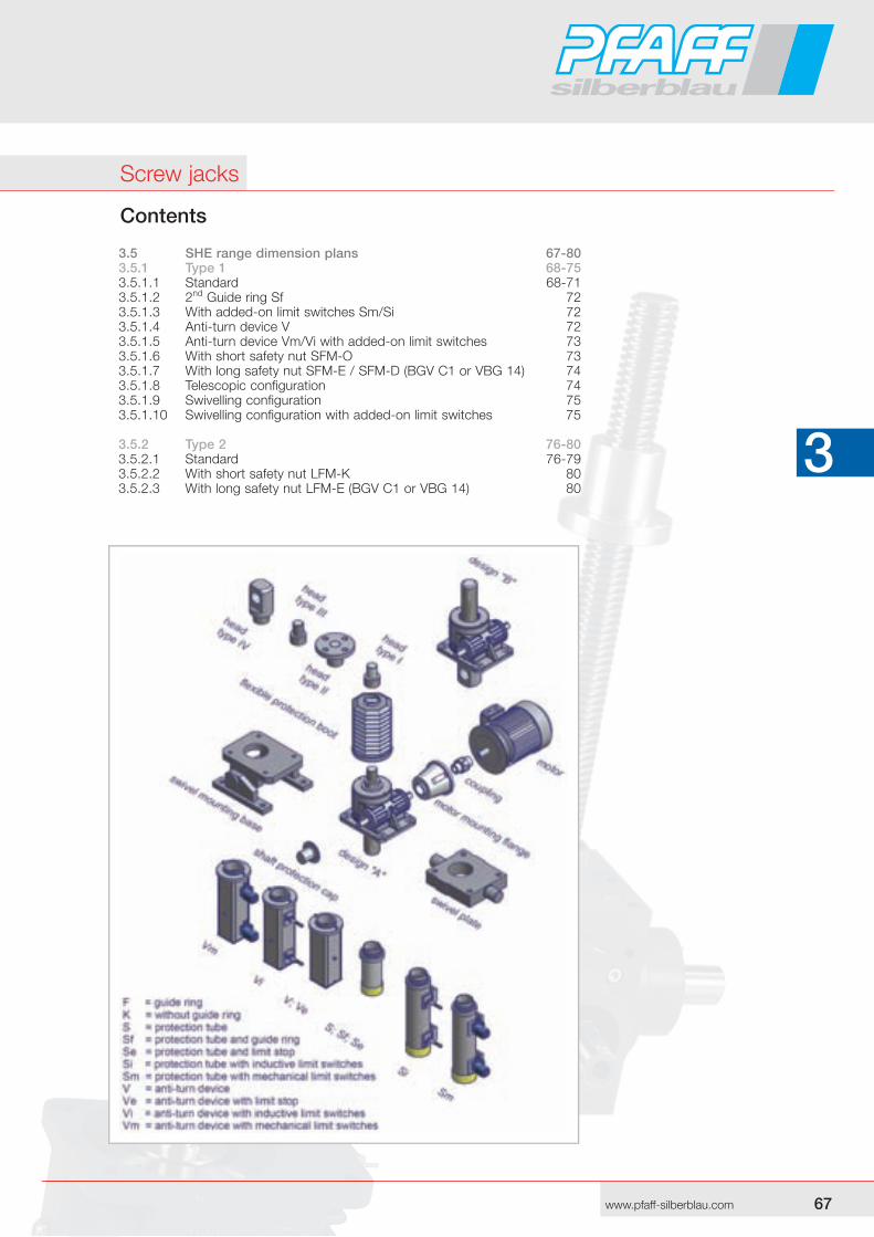
Contents
3.5 SHE range dimension plans 67-803.5.1 Type 1 68-753.5.1.1 Standard 68-713.5.1.2 2nd Guide ring Sf 723.5.1.3 With added-on limit switches Sm/Si 723.5.1.4 Anti-turn device V 723.5.1.5 Anti-turn device Vm/Vi with added-on limit switches 733.5.1.6 With short safety nut SFM-O 733.5.1.7 With long safety nut SFM-E / SFM-D (BGV C1 or VBG 14) 743.5.1.8 Telescopic configuration 743.5.1.9 Swivelling configuration 753.5.1.10 Swivelling configuration with added-on limit switches 75 3.5.2 Type 2 76-803.5.2.1 Standard 76-793.5.2.2 With short safety nut LFM-K 803.5.2.3 With long safety nut LFM-E (BGV C1 or VBG 14) 80
Screw jacks
68 69www.pfaff-silberblau.com
3 3
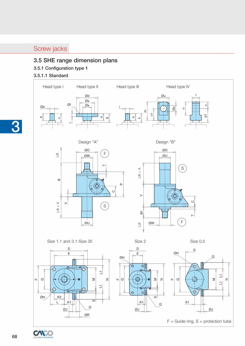
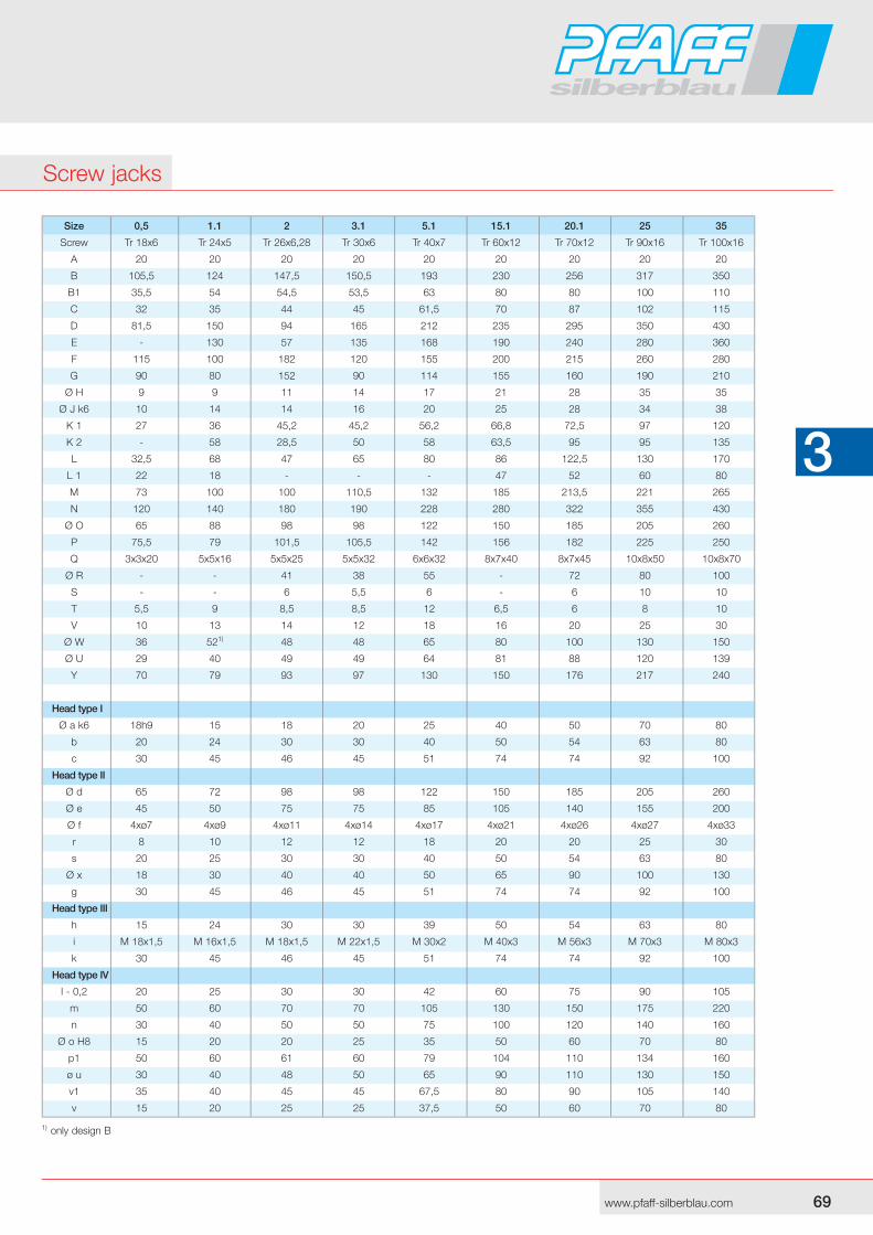
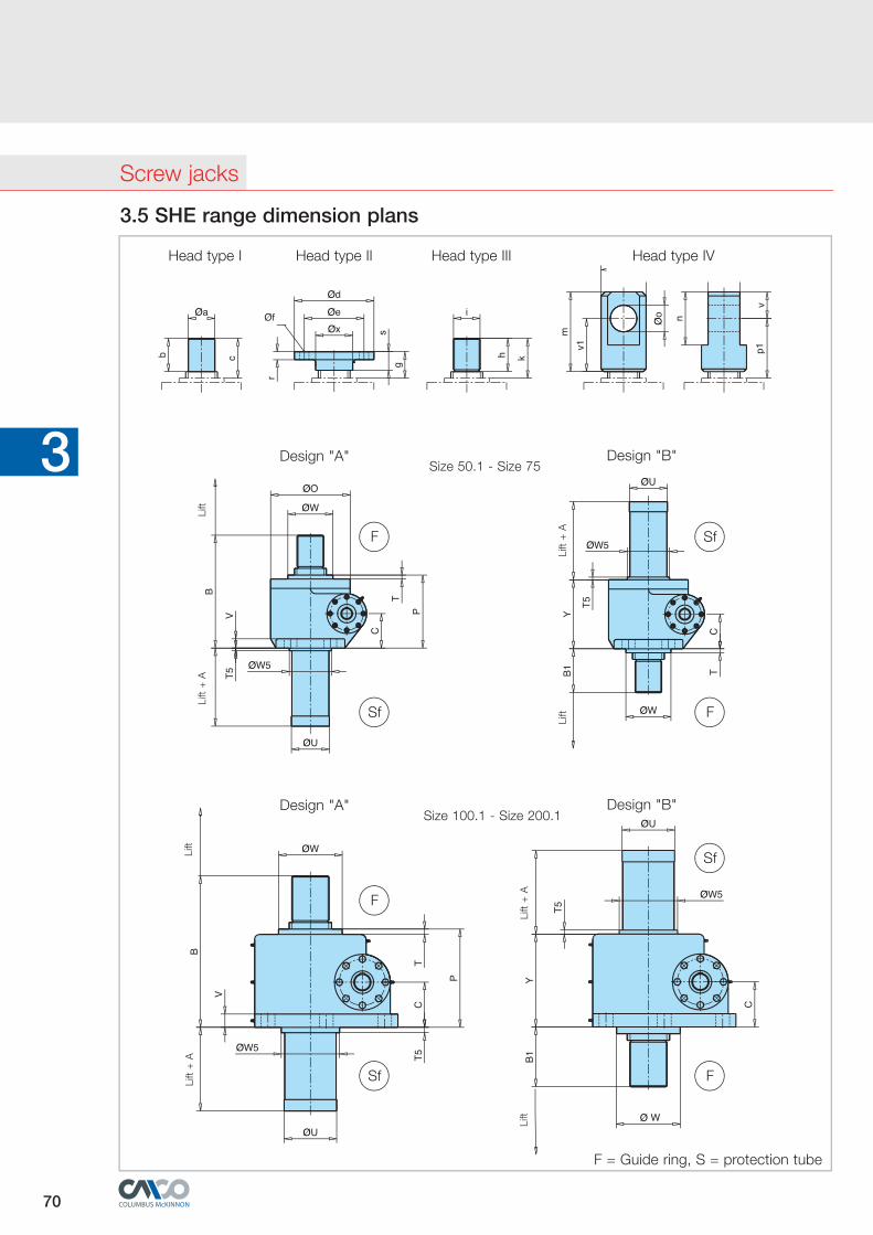
3.5 SHE range dimension plans3.5.1 Configuration type 1
3.5.1.1 Standard
Kopf I Kopf II Kopf III Kopf IV
Design "A" Design "B"
Size 1.1 and 3.1-Size 35 Size 2 Size 0,5
Head type I Head type II Head type III Head type IV
Lift
+ A
Lift
Lift
Lift
+ A
F = Guide ring, S = protection tube
F
S
S
F
Screw jacks
68 69www.pfaff-silberblau.com
3 3
1) only design B
Size 0,5 1.1 2 3.1 5.1 15.1 20.1 25 35
Screw Tr 18x6 Tr 24x5 Tr 26x6,28 Tr 30x6 Tr 40x7 Tr 60x12 Tr 70x12 Tr 90x16 Tr 100x16
A 20 20 20 20 20 20 20 20 20
B 105,5 124 147,5 150,5 193 230 256 317 350
B1 35,5 54 54,5 53,5 63 80 80 100 110
C 32 35 44 45 61,5 70 87 102 115
D 81,5 150 94 165 212 235 295 350 430
E - 130 57 135 168 190 240 280 360
F 115 100 182 120 155 200 215 260 280
G 90 80 152 90 114 155 160 190 210
Ø H 9 9 11 14 17 21 28 35 35
Ø J k6 10 14 14 16 20 25 28 34 38
K 1 27 36 45,2 45,2 56,2 66,8 72,5 97 120
K 2 - 58 28,5 50 58 63,5 95 95 135
L 32,5 68 47 65 80 86 122,5 130 170
L 1 22 18 - - - 47 52 60 80
M 73 100 100 110,5 132 185 213,5 221 265
N 120 140 180 190 228 280 322 355 430
Ø O 65 88 98 98 122 150 185 205 260
P 75,5 79 101,5 105,5 142 156 182 225 250
Q 3x3x20 5x5x16 5x5x25 5x5x32 6x6x32 8x7x40 8x7x45 10x8x50 10x8x70
Ø R - - 41 38 55 - 72 80 100
S - - 6 5,5 6 - 6 10 10
T 5,5 9 8,5 8,5 12 6,5 6 8 10
V 10 13 14 12 18 16 20 25 30
Ø W 36 521) 48 48 65 80 100 130 150
Ø U 29 40 49 49 64 81 88 120 139
Y 70 79 93 97 130 150 176 217 240
Head type I
Ø a k6 18h9 15 18 20 25 40 50 70 80
b 20 24 30 30 40 50 54 63 80
c 30 45 46 45 51 74 74 92 100
Head type II
Ø d 65 72 98 98 122 150 185 205 260
Ø e 45 50 75 75 85 105 140 155 200
Ø f 4xø7 4xø9 4xø11 4xø14 4xø17 4xø21 4xø26 4xø27 4xø33
r 8 10 12 12 18 20 20 25 30
s 20 25 30 30 40 50 54 63 80
Ø x 18 30 40 40 50 65 90 100 130
g 30 45 46 45 51 74 74 92 100
Head type III
h 15 24 30 30 39 50 54 63 80
i M 18x1,5 M 16x1,5 M 18x1,5 M 22x1,5 M 30x2 M 40x3 M 56x3 M 70x3 M 80x3
k 30 45 46 45 51 74 74 92 100
Head type IV
l - 0,2 20 25 30 30 42 60 75 90 105
m 50 60 70 70 105 130 150 175 220
n 30 40 50 50 75 100 120 140 160
Ø o H8 15 20 20 25 35 50 60 70 80
p1 50 60 61 60 79 104 110 134 160
ø u 30 40 48 50 65 90 110 130 150
v1 35 40 45 45 67,5 80 90 105 140
v 15 20 25 25 37,5 50 60 70 80
Screw jacks
70 71www.pfaff-silberblau.com
3 3Size 50.1 - Size 75
Size 100.1 - Size 200.1
Head type I Head type II Head type III Head type IV
Design "A" Design "B"
Design "A" Design "B"
Lift
+ A
Lift
Lift
+ A
Lift
Lift
+ A
Lift
Lift
+ A
Lift
3.5 SHE range dimension plans
F
Sf
Sf
F
F
Sf
Sf
F
F = Guide ring, S = protection tube
Screw jacks
70 71www.pfaff-silberblau.com
3 3
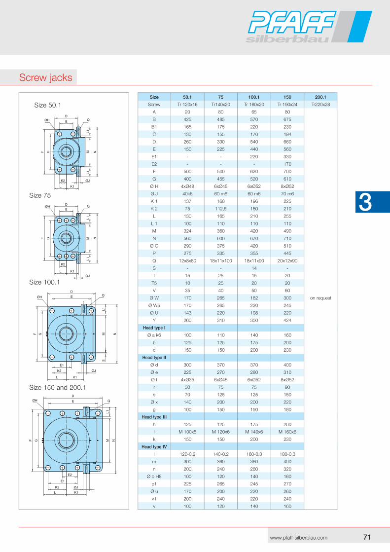
Size 150 and 200.1
Size 100.1
Size 75
Size 50.1 Size 50.1 75 100.1 150 200.1
Screw Tr 120x16 Tr140x20 Tr 160x20 Tr 190x24 Tr220x28
A 20 80 65 80
B 425 485 570 675
B1 165 175 220 230
C 130 155 170 194
D 260 330 540 660
E 150 225 440 560
E1 - - 220 330
E2 - - - 170
F 500 540 620 700
G 400 455 520 610
Ø H 4xØ48 6xØ45 6xØ52 8xØ52
Ø J 40k6 60 m6 60 m6 70 m6
K 1 137 160 196 225
K 2 75 112,5 160 210
L 130 165 210 255
L 1 100 110 110 110
M 324 360 420 490
N 560 600 670 710
Ø O 290 375 420 510
P 275 335 355 445
Q 12x8x80 18x11x100 18x11x90 20x12x90
S - - 14 -
T 15 25 15 20
T5 10 25 20 20
V 35 40 50 60
Ø W 170 265 182 300 on request
Ø W5 170 265 220 245
Ø U 143 220 198 220
Y 260 310 350 424
Head type I
Ø a k6 100 110 140 160
b 125 125 175 200
c 150 150 200 230
Head type II
Ø d 300 370 370 400
Ø e 225 270 280 310
Ø f 4xØ35 6xØ45 6xØ52 8xØ52
r 30 75 75 90
s 70 125 125 150
Ø x 140 200 200 220
g 100 150 150 180
Head type III
h 125 125 175 200
i M 100x5 M 120x6 M 140x6 M 160x6
k 150 150 200 230
Head type IV
l 120-0,2 140-0,2 160-0,3 180-0,3
m 300 360 360 400
n 200 240 280 320
Ø o H8 100 120 140 160
p1 225 265 245 270
Ø u 170 200 220 260
v1 200 240 220 240
v 100 120 140 160
Screw jacks

72 73www.pfaff-silberblau.com
3 3
3.5.1.4 Anti-turn device V
The screw must be prevented from twisting in order to ensure cor-rect lin ear movement. This measure can be provided on site or by means of an anti-turn device fitted to the SHE unit using a square tube.
Lift+
A3
Lift+
A1
Size A3 T3 ØW3 A1 T1 ØW1 U1
0,5 65 9 52 60 - - 30 x30
1.1 74 8 80 74 8 80 40x40
2 85 8 65 77 - - 40x40
3.1 85 8 70 77 - - 50x50
5.1 95 10 110 85 - - 80x80
15.1 115 15 130 100 - - 90x90
20.1 100 20 160 100 20 160 100x100
25 110 20 180 110 20 160 120x120
35 115 20 200 115 20 200 140x140
50.1 158 15 240 158 15 240 180x180
75 170 20 300 170 20 300 220x220
100.1 170 10 300 170 15 300 200x200
150 210 20 380 210 20 380 260x260
200.1 on request
V
3.5 SHE range dimension plans
3.5.1.2 2nd Guide ring Sf
If no guides can be fitted on site and restoring forces produced by swivelling motion or lateral forces cannot be ruled out the SHE unit should be fitted with a 2nd guide ring.
Lift+
A2
Lift+
A2
Sf
Size A2 T2 ØW2 ØU
0,5 32 11,5 36 29
1.1 32 9 521) 40
2 44 20 60 49
3.1 40 20 60 49
5.1 43 18 75 64
15.1 42 18 95 81
20.1 55 31 100 88
25 65 40 130 120
35 60 40 150 139
50.1 143
75 220
100.1 198
150 220
200.1
Standard design with
2nd guide ring
1) only design A3.5.1.3 With added-on limit switches Sm/Si
All sizes can be supplied with mechanical or inductive limit switches.
Si Sm Lift+
D
Lift+
A4
Size A4 B B1 C D T M ØU ØW2 X
1.1 on request
2 160 92 100 60 20 58 12x1 60 44,5 ±10
3.1 170 100 106 65 25 58 12x1 75 60,3 ±10
5.1 175 107 115 70 25 58 12x1 95 76,1 ±10
15.1 185 114 122 75 30 58 12x1 110 88,9 ±10
20.1 195 131 130 80 40 58 12x1 125 114,3 ±10
25 225 141 137 90 50 65 18x1 150 133 ±10
35
50.1 on request
75 204 171 178 75 70 58 18x1 265 219,1 ±10
100.1; 150; 200.1; on request
Screw jacks
72 73www.pfaff-silberblau.com
3 3
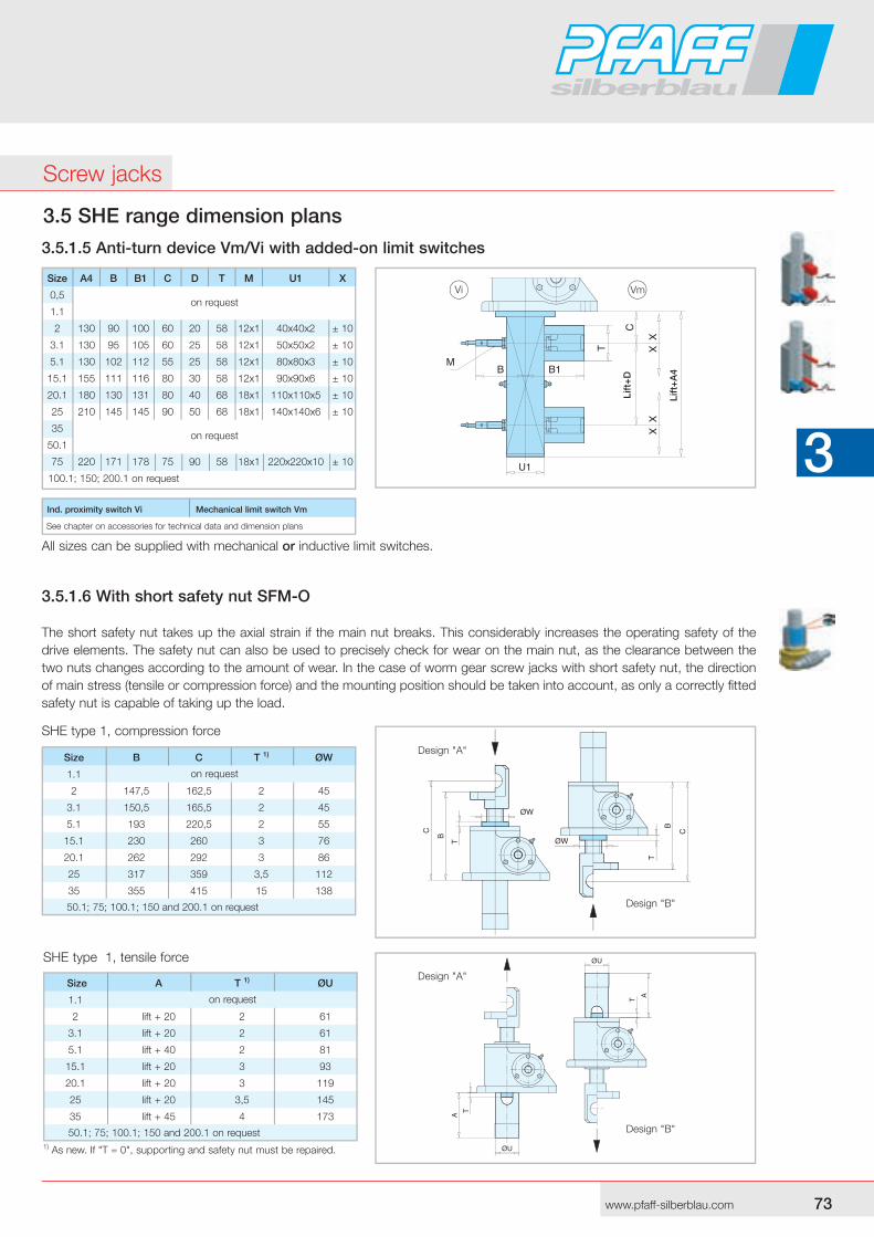
3.5.1.6 With short safety nut SFM-O
The short safety nut takes up the axial strain if the main nut breaks. This considerably increases the operating safety of the drive elements. The safety nut can also be used to precisely check for wear on the main nut, as the clearance between the two nuts changes according to the amount of wear. In the case of worm gear screw jacks with short safety nut, the direction of main stress (tensile or compression force) and the mounting position should be taken into account, as only a correctly fitted safety nut is capable of taking up the load.
SHE type 1, compression force
SHE type 1, tensile force
Design "A"
Design "A"
Design "B"
Design "B"
1) As new. If "T = 0", supporting and safety nut must be repaired.
Size A T 1) ØU
1.1
2 lift + 20 2 61
3.1 lift + 20 2 61
5.1 lift + 40 2 81
15.1 lift + 20 3 93
20.1 lift + 20 3 119
25 lift + 20 3,5 145
35 lift + 45 4 173
50.1; 75; 100.1; 150 and 200.1 on request
on request
Size B C T 1) ØW
1.1
2 147,5 162,5 2 45
3.1 150,5 165,5 2 45
5.1 193 220,5 2 55
15.1 230 260 3 76
20.1 262 292 3 86
25 317 359 3,5 112
35 355 415 15 138
50.1; 75; 100.1; 150 and 200.1 on request
on request
3.5 SHE range dimension plans
3.5.1.5 Anti-turn device Vm/Vi with added-on limit switches
Ind. proximity switch Vi Mechanical limit switch Vm
See chapter on accessories for technical data and dimension plans
All sizes can be supplied with mechanical or inductive limit switches.
Size A4 B B1 C D T M U1 X
0,5
1.1
2 130 90 100 60 20 58 12x1 40x40x2 ± 10
3.1 130 95 105 60 25 58 12x1 50x50x2 ± 10
5.1 130 102 112 55 25 58 12x1 80x80x3 ± 10
15.1 155 111 116 80 30 58 12x1 90x90x6 ± 10
20.1 180 130 131 80 40 68 18x1 110x110x5 ± 10
25 210 145 145 90 50 68 18x1 140x140x6 ± 10
35
50.1
75 220 171 178 75 90 58 18x1 220x220x10 ± 10
100.1; 150 ; 200.1 on request
on request
on request
Vi Vm
Lift
+D
Lift
+A
4
Screw jacks
74 75www.pfaff-silberblau.com
3 3
3.5 SHE range dimension plans
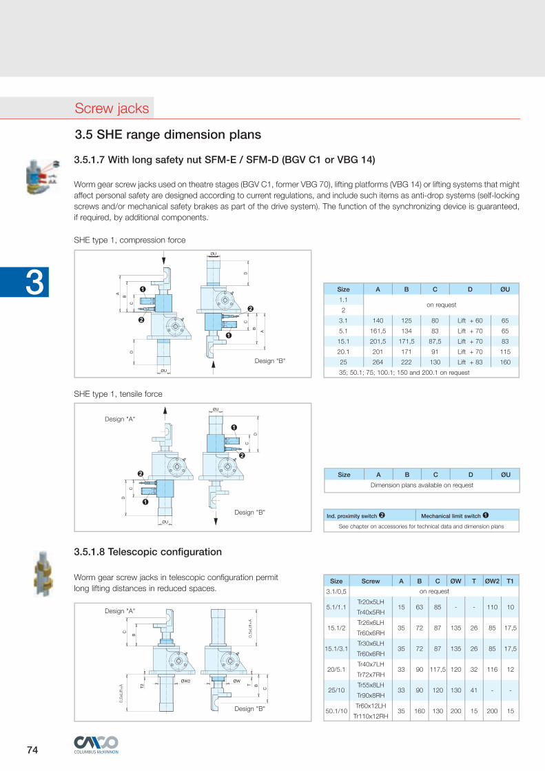
Worm gear screw jacks used on theatre stages (BGV C1, former VBG 70), lifting platforms (VBG 14) or lifting systems that might affect personal safety are designed according to current regulations, and include such items as anti-drop systems (self-locking screws and/or mechanical safety brakes as part of the drive system). The function of the synchronizing device is guaranteed, if required, by additional components.
3.5.1.7 With long safety nut SFM-E / SFM-D (BGV C1 or VBG 14)
SHE type 1, compression force
SHE type 1, tensile force
Size A B C D ØU
Dimension plans available on request
3.5.1.8 Telescopic configuration
Worm gear screw jacks in telescopic configuration permitlong lifting distances in reduced spaces.
Design "A"
Design "B"
0,5x
Lift+
A
0,5x
Lift+
A
Size Screw A B C ØW T ØW2 T1
3.1/0,5
5.1/1.1
Tr20x5LH
Tr40x5RH 15 63 85 - - 110 10
15.1/2
Tr26x6LH
Tr60x6RH 35 72 87 135 26 85 17,5
15.1/3.1
Tr30x6LH
Tr60x6RH 35 72 87 135 26 85 17,5
20/5.1
Tr40x7LH
Tr72x7RH 33 90 117,5 120 32 116 12
25/10
Tr55x8LH
Tr90x8RH 33 90 120 130 41 - -
50.1/10
Tr60x12LH
Tr110x12RH 35 160 130 200 15 200 15
on request
Ind. proximity switch ➋ Mechanical limit switch ➊See chapter on accessories for technical data and dimension plans
Size A B C D ØU
1.1
2
3.1 140 125 80 Lift + 60 65
5.1 161,5 134 83 Lift + 70 65
15.1 201,5 171,5 87,5 Lift + 70 83
20.1 201 171 91 Lift + 70 115
25 264 222 130 Lift + 83 160
35; 50.1; 75; 100.1; 150 and 200.1 on request
on request
Design "A"
Design "B"
➊
➋
➊
➋
Design "A"
➊
➋➋
➊
Design "B"
Screw jacks
74 75www.pfaff-silberblau.com
3 3
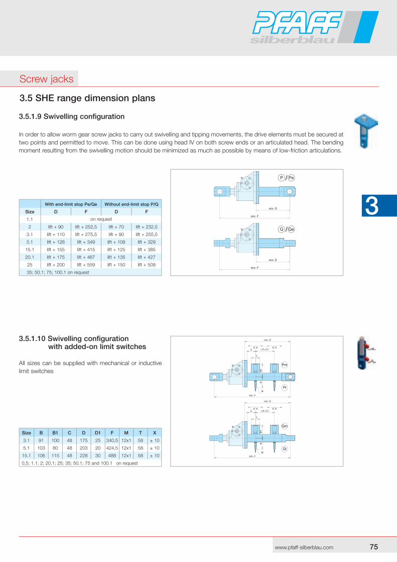
3.5.1.10 Swivelling configuration with added-on limit switches
All sizes can be supplied with mechanical or inductive limit switches
Lift+D1
Lift+D1
Size B B1 C D D1 F M T X
3.1 91 100 48 175 25 340,5 12x1 58 ± 10
5.1 103 80 48 203 20 424,5 12x1 58 ± 10
15.1 106 115 48 228 30 488 12x1 58 ± 10
0,5; 1.1; 2; 20.1; 25; 35 ; 50.1; 75 and 100.1 on request
With end-limit stop Pe/Qe Without end-limit stop P/Q
Size D F D F
1.1
2 lift + 90 lift + 252,5 lift + 70 lift + 232,5
3.1 lift + 110 lift + 275,5 lift + 90 lift + 255,5
5.1 lift + 128 lift + 349 lift + 108 lift + 329
15.1 lift + 155 lift + 415 lift + 125 lift + 385
20.1 lift + 175 lift + 467 lift + 135 lift + 427
25 lift + 200 lift + 559 lift + 150 lift + 509
35; 50.1; 75; 100.1 on request
on request
3.5 SHE range dimension plans
3.5.1.9 Swivelling configuration
In order to allow worm gear screw jacks to carry out swiv el ling and tipping movements, the drive elements must be secured at two points and permitted to move. This can be done using head IV on both screw ends or an articulated head. The bending moment resulting from the swivelling motion should be minimized as much as possible by means of low-friction articulations.
Screw jacks
76 77www.pfaff-silberblau.com
3 3
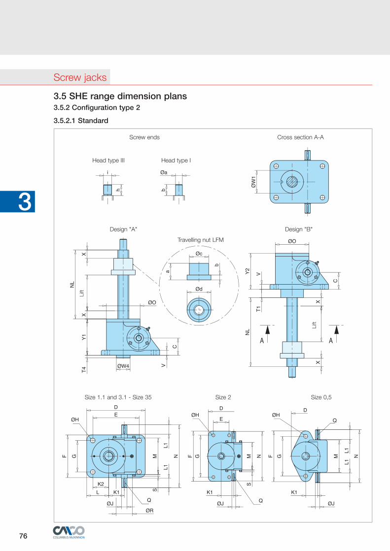
3.5 SHE range dimension plans3.5.2 Configuration type 2
3.5.2.1 Standard
Design "A"
Screw ends Cross section A-A
Travelling nut LFM
Head type IHead type III
Design "B"
Size 1.1 and 3.1 - Size 35 Size 2 Size 0,5
Lift
Lift
Screw jacks
76 77www.pfaff-silberblau.com
3 3
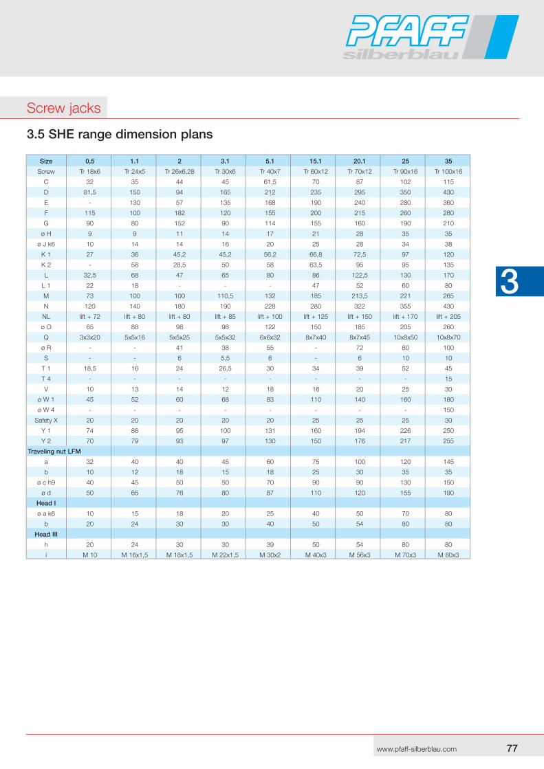
3.5 SHE range dimension plans
Screw jacks
Size 0,5 1.1 2 3.1 5.1 15.1 20.1 25 35
Screw Tr 18x6 Tr 24x5 Tr 26x6,28 Tr 30x6 Tr 40x7 Tr 60x12 Tr 70x12 Tr 90x16 Tr 100x16
C 32 35 44 45 61,5 70 87 102 115
D 81,5 150 94 165 212 235 295 350 430
E - 130 57 135 168 190 240 280 360
F 115 100 182 120 155 200 215 260 280
G 90 80 152 90 114 155 160 190 210
ø H 9 9 11 14 17 21 28 35 35
ø J k6 10 14 14 16 20 25 28 34 38
K 1 27 36 45,2 45,2 56,2 66,8 72,5 97 120
K 2 - 58 28,5 50 58 63,5 95 95 135
L 32,5 68 47 65 80 86 122,5 130 170
L 1 22 18 - - - 47 52 60 80
M 73 100 100 110,5 132 185 213,5 221 265
N 120 140 180 190 228 280 322 355 430
NL lift + 72 lift + 80 lift + 80 lift + 85 lift + 100 lift + 125 lift + 150 lift + 170 lift + 205
ø O 65 88 98 98 122 150 185 205 260
Q 3x3x20 5x5x16 5x5x25 5x5x32 6x6x32 8x7x40 8x7x45 10x8x50 10x8x70
ø R - - 41 38 55 - 72 80 100
S - - 6 5,5 6 - 6 10 10
T 1 18,5 16 24 26,5 30 34 39 52 45
T 4 - - - - - - - - 15
V 10 13 14 12 18 16 20 25 30
ø W 1 45 52 60 68 83 110 140 160 180
ø W 4 - - - - - - - - 150
Safety X 20 20 20 20 20 25 25 25 30
Y 1 74 86 95 100 131 160 194 226 250
Y 2 70 79 93 97 130 150 176 217 255
Traveling nut LFM
a 32 40 40 45 60 75 100 120 145
b 10 12 18 15 18 25 30 35 35
ø c h9 40 45 50 50 70 90 90 130 150
ø d 50 65 76 80 87 110 120 155 190
Head I
ø a k6 10 15 18 20 25 40 50 70 80
b 20 24 30 30 40 50 54 80 80
Head III
h 20 24 30 30 39 50 54 80 80
i M 10 M 16x1,5 M 18x1,5 M 22x1,5 M 30x2 M 40x3 M 56x3 M 70x3 M 80x3
78 79www.pfaff-silberblau.com
3 3
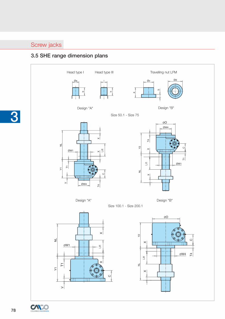
3.5 SHE range dimension plans
Head type I Head type III Travelling nut LFM
Design "A" Design "B"
Design "A" Design "B"
Size 100.1 - Size 200.1
Lift
Lift
Lift
Lift
Size 50.1 - Size 75
Screw jacks
78 79www.pfaff-silberblau.com
3 3
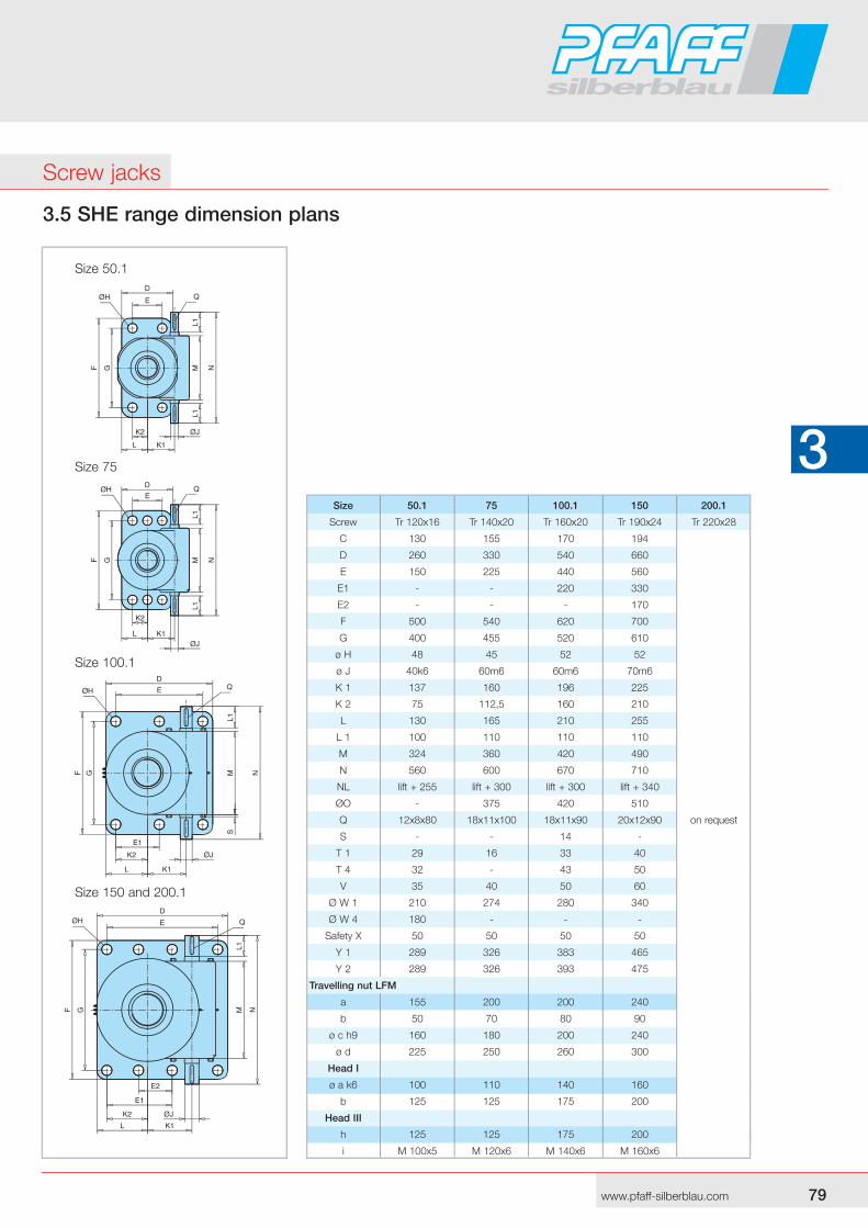
3.5 SHE range dimension plans
Size 150 and 200.1
Size 100.1
Size 75
Size 50.1
Screw jacks
Size 50.1 75 100.1 150 200.1
Screw Tr 120x16 Tr 140x20 Tr 160x20 Tr 190x24 Tr 220x28
C 130 155 170 194
D 260 330 540 660
E 150 225 440 560
E1 - - 220 330
E2 - - - 170
F 500 540 620 700
G 400 455 520 610
ø H 48 45 52 52
ø J 40k6 60m6 60m6 70m6
K 1 137 160 196 225
K 2 75 112,5 160 210
L 130 165 210 255
L 1 100 110 110 110
M 324 360 420 490
N 560 600 670 710
NL lift + 255 lift + 300 lift + 300 lift + 340
ØO - 375 420 510
Q 12x8x80 18x11x100 18x11x90 20x12x90 on request
S - - 14 -
T 1 29 16 33 40
T 4 32 - 43 50
V 35 40 50 60
Ø W 1 210 274 280 340
Ø W 4 180 - - -
Safety X 50 50 50 50
Y 1 289 326 383 465
Y 2 289 326 393 475
Travelling nut LFM
a 155 200 200 240
b 50 70 80 90
ø c h9 160 180 200 240
ø d 225 250 260 300
Head I
ø a k6 100 110 140 160
b 125 125 175 200
Head III
h 125 125 175 200
i M 100x5 M 120x6 M 140x6 M 160x6
80 MFwww.pfaff-silberblau.com
3 3
3.5 SHE range dimension plans
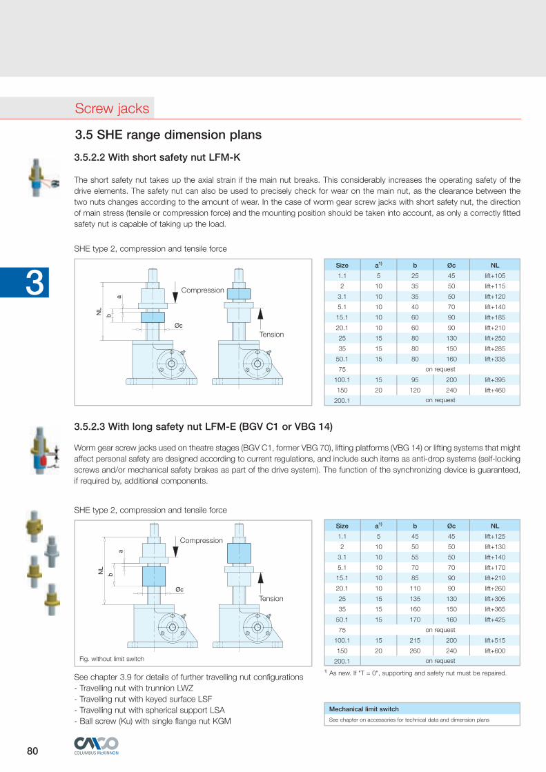
3.5.2.2 With short safety nut LFM-K
The short safety nut takes up the axial strain if the main nut breaks. This consid erably increases the operating safety of the drive elements. The safety nut can also be used to precisely check for wear on the main nut, as the clear ance between the two nuts changes according to the amount of wear. In the case of worm gear screw jacks with short safety nut, the direction of main stress (tensile or compression force) and the mounting position should be tak en into account, as only a correctly fitted safety nut is capable of taking up the load.
Worm gear screw jacks used on theatre stages (BGV C1, former VBG 70), lifting platforms (VBG 14) or lifting systems that might affect personal safety are designed according to current regulations, and include such items as anti-drop systems (self-locking screws and/or mechanical safety brakes as part of the drive system). The function of the synchronizing device is guaranteed, if required by, additional components.
3.5.2.3 With long safety nut LFM-E (BGV C1 or VBG 14)
SHE type 2, compression and tensile force
Compression
Tension
Size a1) b Øc NL
1.1 5 25 45 lift+105
2 10 35 50 lift+115
3.1 10 35 50 lift+120
5.1 10 40 70 lift+140
15.1 10 60 90 lift+185
20.1 10 60 90 lift+210
25 15 80 130 lift+250
35 15 80 150 lift+285
50.1 15 80 160 lift+335
75
100.1 15 95 200 lift+395
150 20 120 240 lift+460
200.1
on request
on request
SHE type 2, compression and tensile force
Mechanical limit switch
See chapter on accessories for technical data and dimension plans
1) As new. If "T = 0", supporting and safety nut must be repaired.See chapter 3.9 for details of further travelling nut configurations- Travelling nut with trunnion LWZ- Travelling nut with keyed surface LSF- Travelling nut with spherical support LSA- Ball screw (Ku) with single flange nut KGM
Size a1) b Øc NL
1.1 5 45 45 lift+125
2 10 50 50 lift+130
3.1 10 55 50 lift+140
5.1 10 70 70 lift+170
15.1 10 85 90 lift+210
20.1 10 110 90 lift+260
25 15 135 130 lift+305
35 15 160 150 lift+365
50.1 15 170 160 lift+425
75
100.1 15 215 200 lift+515
150 20 260 240 lift+600
200.1
on request
on request
Screw jacks
Tension
Compression
Fig. without limit switch
MF 81www.pfaff-silberblau.com
3 3
Contents
3.6 MERKUR range dimension plans 81-883.6.1 Type 1 82-853.6.1.1 Standard 82-833.6.1.2 2nd Guide ring 2FR 843.6.1.3 With added-on limit switches Sm/Si 843.6.1.4 Anti-turn device V 843.6.1.5 Anti-turn device Vm/Vi with added-on limit switches 843.6.1.6 Mounting brackets 85
3.6.2 Type 2 86-883.6.2.1 Standard 86-873.6.2.2 With short safety nut LFM-K 883.6.2.3 With long safety nut LFM-E (BGV C1 or VBG 14) 88
Screw jacks
82 83www.pfaff-silberblau.com
3 3
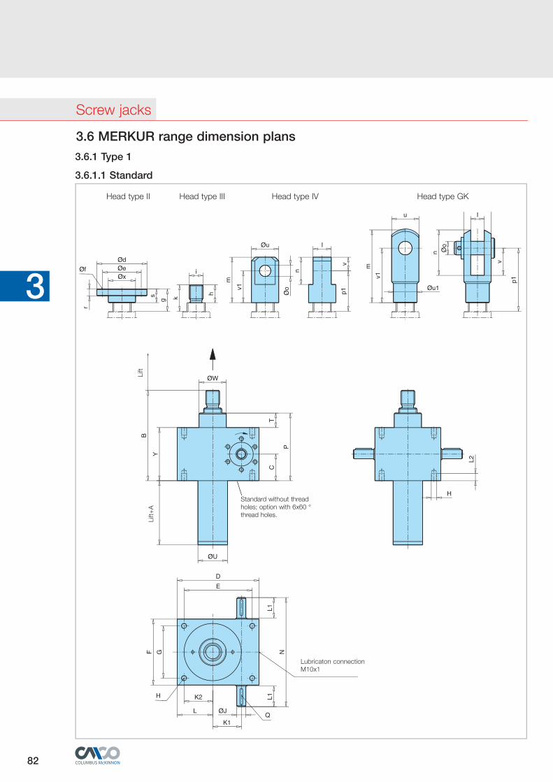
3.6 MERKUR range dimension plans
3.6.1 Type 1
3.6.1.1 Standard
Kopf GKKopf II Kopf III Kopf IVHead type II Head type III Head type IV Head type GK
Lift+
A
Lift
Lubricaton connection M10x1
Standard without thread holes; option with 6x60 °thread holes.
Screw jacks
82 83www.pfaff-silberblau.com
3 3
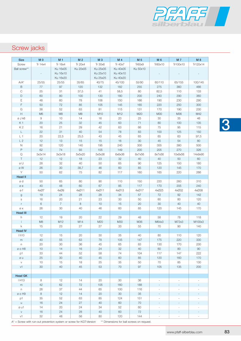
A* = Screw with run-out prevention system or screw for KGT-Version ** Dimensions for ball screws on request.
Size M 0 M 1 M 2 M 3 M 4 M 5 M 6 M 7 M 8
Screw Tr 14x4 Tr 18x4 Tr 20x4 Tr 30x6 Tr 40x7 Tr60x9 Tr80x10 Tr100x10 Tr120x14
Ball screw** Ku 16x05 Ku 20x05 Ku 25x05 Ku 40x05 Ku 50x10
- - - - Ku 16x10 Ku 25x10 Ku 40x10
Ku 16x20 Ku 25x25 Ku 40x20
A/A* 25/55 25/55 35/65 40/75 45/100 55/90 60/110 65/155 100/145
B 77 97 120 132 182 255 275 360 466
C 25 31 37,5 41 58,5 80 82,5 110 133
D 60 80 100 130 180 200 240 290 360
E 48 60 78 106 150 166 190 230 290
F 50 72 85 105 145 165 220 250 300
G 38 52 63 81 115 131 170 190 230
H M6 M8 M8 M10 M12 M20 M30 M36 M42
ø J k6 9 10 14 16 20 25 30 35 48
K 1 20 25 32 45 63 71 80 100 135
K 2 16 21 29 42 63 66 75 95 115
L 22 31 40 54 78 83 100 125 150
L 1 20 22,5 25,5 43 45 65 65 63 97,5
L 2 12 13 15 15 16 30 45 54 80
N 92 120 140 195 240 300 355 380 500
P 62 74 93 105 149 200 205 270 326
Q 3x3x14 3x3x18 5x5x20 5x5x36 6x6x36 8x7x56 8x7x56 10x8x56 14x9x90
T 12 12 18 23 32 40 40 50 60
ø U 28 32 40 50 65 90 125 150 180
ø W 26 30 38,7 46 60 85 120 145 170
Y 50 62 75 82 117 160 165 220 266
Head II
ø d 50 65 80 90 110 150 220 260 310
ø e 40 48 60 67 85 117 170 205 240
ø f 4xØ7 4xØ9 4xØ11 4xØ11 4xØ13 4xØ17 4xØ25 4xØ32 4xØ38
g 19 24 28 28 34 57 72 92 142
s 16 20 21 23 30 50 60 80 120
r 6 7 8 10 15 20 30 40 40
ø x 26 30 40 46 60 85 120 145 170
Head III
h 12 19 20 22 29 48 58 78 118
i M8 M12 M14 M20 M30 M36 M64x3 M72x3 M100x3
k 15 23 27 27 33 55 70 90 140
Head IV
l h10 12 15 20 30 35 40 80 110 120
m 40 55 63 78 105 147 175 220 330
n 20 30 36 45 65 83 130 170 230
ø o H8 10 14 16 24 32 40 60 80 90
p1 33 44 52 58 74 104 117 147 222
ø u 25 30 40 45 60 85 120 160 170
v 10 15 18 25 35 50 70 85 130
v1 30 40 45 53 70 97 105 135 200
Head GK
l H13 8 12 14 20 30 36 - - -
m 42 62 72 105 160 188 - - -
n 26 37 44 65 100 116 - - -
ø o H9 8 12 14 20 30 35 - - -
p1 35 52 63 85 124 151 - - -
u 16 24 27 40 60 70 - - -
ø u1 14 20 24 34 52 60 - - -
v 16 24 28 40 60 72 - - -
v1 32 48 56 80 120 144 - - -
Screw jacks
84 85www.pfaff-silberblau.com
3 3
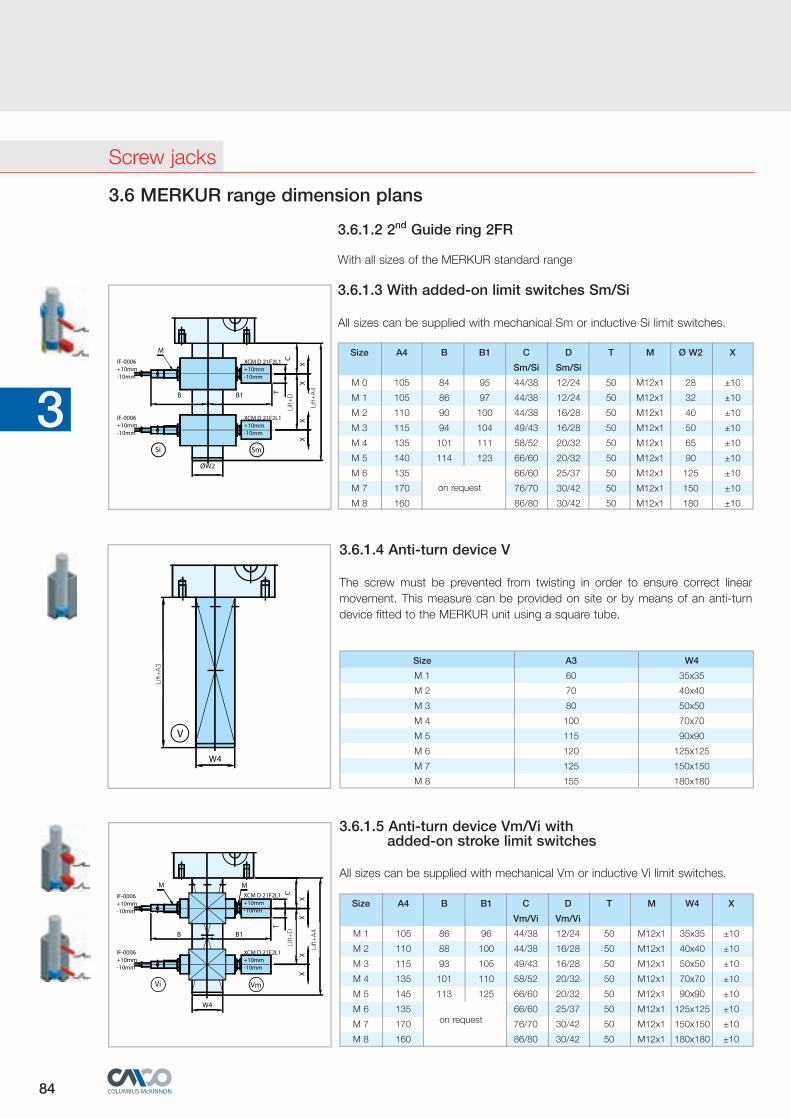
3.6.1.4 Anti-turn device V
The screw must be prevented from twisting in order to ensure correct linear movement. This measure can be provided on site or by means of an anti-turn device fitted to the MERKUR unit using a square tube.
Size A3 W4
M 1 60 35x35
M 2 70 40x40
M 3 80 50x50
M 4 100 70x70
M 5 115 90x90
M 6 120 125x125
M 7 125 150x150
M 8 155 180x180
Lift+
A3
All sizes can be supplied with mechanical Vm or inductive Vi limit switches.
3.6.1.5 Anti-turn device Vm/Vi with added-on stroke limit switches
Size A4 B B1 C D T M W4 X
Vm/Vi Vm/Vi
M 1 105 86 96 44/38 12/24 50 M12x1 35x35 ±10
M 2 110 88 100 44/38 16/28 50 M12x1 40x40 ±10
M 3 115 93 105 49/43 16/28 50 M12x1 50x50 ±10
M 4 135 101 110 58/52 20/32 50 M12x1 70x70 ±10
M 5 145 113 125 66/60 20/32 50 M12x1 90x90 ±10
M 6 135 on request
66/60 25/37 50 M12x1 125x125 ±10
M 7 170 76/70 30/42 50 M12x1 150x150 ±10
M 8 160 86/80 30/42 50 M12x1 180x180 ±10
Lift+
D
Lift+
A4
3.6 MERKUR range dimension plans
3.6.1.2 2nd Guide ring 2FR
With all sizes of the MERKUR standard range
Size A4 B B1 C D T M Ø W2 X
Sm/Si Sm/Si
M 0 105 84 95 44/38 12/24 50 M12x1 28 ±10
M 1 105 86 97 44/38 12/24 50 M12x1 32 ±10
M 2 110 90 100 44/38 16/28 50 M12x1 40 ±10
M 3 115 94 104 49/43 16/28 50 M12x1 50 ±10
M 4 135 101 111 58/52 20/32 50 M12x1 65 ±10
M 5 140 114 123 66/60 20/32 50 M12x1 90 ±10
M 6 135
on request
66/60 25/37 50 M12x1 125 ±10
M 7 170 76/70 30/42 50 M12x1 150 ±10
M 8 160 86/80 30/42 50 M12x1 180 ±10
Lift+
D
Lift+
A4
3.6.1.3 With added-on limit switches Sm/Si
All sizes can be supplied with mechanical Sm or inductive Si limit switches.
Screw jacks
84 85www.pfaff-silberblau.com
3 3
3.6 MERKUR range dimension plans
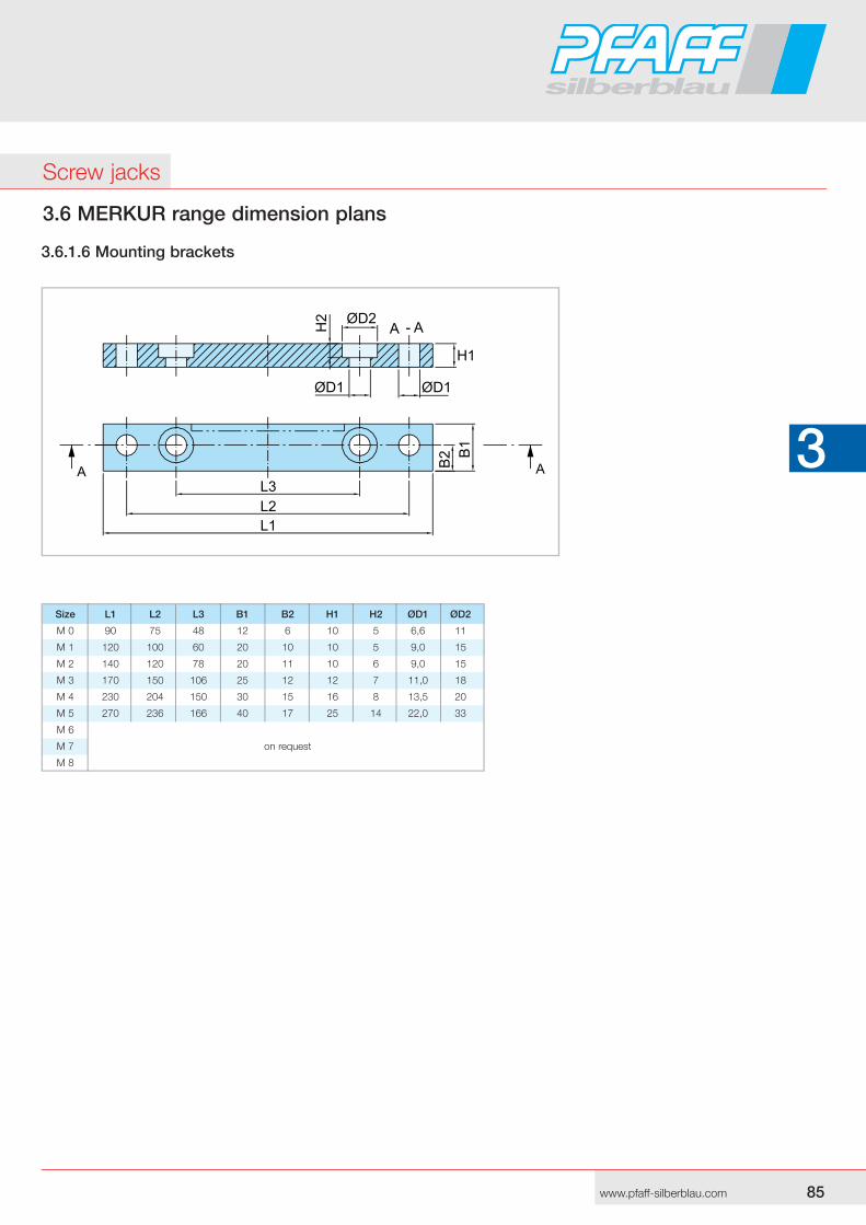
3.6.1.6 Mounting brackets
Size L1 L2 L3 B1 B2 H1 H2 ØD1 ØD2
M 0 90 75 48 12 6 10 5 6,6 11
M 1 120 100 60 20 10 10 5 9,0 15
M 2 140 120 78 20 11 10 6 9,0 15
M 3 170 150 106 25 12 12 7 11,0 18
M 4 230 204 150 30 15 16 8 13,5 20
M 5 270 236 166 40 17 25 14 22,0 33
M 6
M 7 on request
M 8
Screw jacks
86 87www.pfaff-silberblau.com
3 3
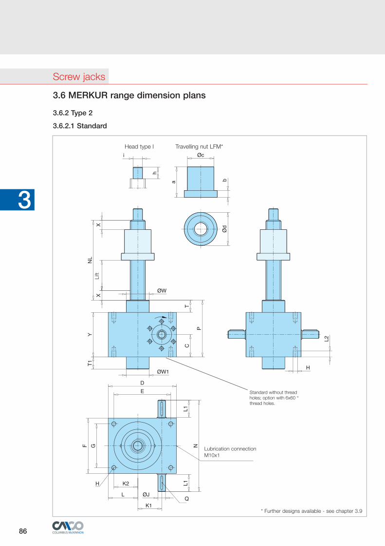
3.6 MERKUR range dimension plans
Head type I Travelling nut LFM*
Lift
Lubrication connectionM10x1
* Further designs available - see chapter 3.9
Standard without thread holes; option with 6x60 °thread holes.
3.6.2 Type 2
3.6.2.1 Standard
Screw jacks
86 87www.pfaff-silberblau.com
3 3
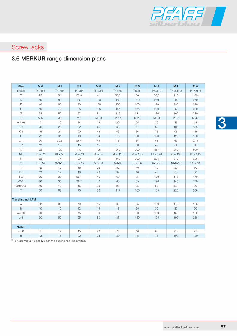
3.6 MERKUR range dimension plans
Screw jacks
Size M 0 M 1 M 2 M 3 M 4 M 5 M 6 M 7 M 8
Screw Tr 14x4 Tr 18x4 Tr 20x4 Tr 30x6 Tr 40x7 Tr60x9 Tr80x10 Tr100x10 Tr120x14
C 25 31 37,5 41 58,5 80 82,5 110 133
D 60 80 100 130 180 200 240 290 360
E 48 60 78 106 150 166 190 230 290
F 50 72 85 105 145 165 220 250 300
G 38 52 63 81 115 131 170 190 230
H M 6 M 8 M 8 M 10 M 12 M 20 M 30 M 36 M 42
ø J k6 9 10 14 16 20 25 30 35 48
K 1 20 25 32 45 63 71 80 100 135
K 2 16 21 29 42 63 66 75 95 115
L 22 31 40 54 78 83 100 125 150
L 1 20 22,5 25,5 43 45 65 65 63 97,5
L 2 12 13 15 15 16 30 40 54 80
N 92 120 140 195 240 300 355 380 500
NL lift + 52 lift + 56 lift + 70 lift + 85 lift + 110 lift + 125 lift + 170 lift + 195 lift + 215
P 62 74 93 105 149 200 205 270 326
Q 3x3x14 3x3x18 5x5x20 5x5x36 6x6x36 8x7x56 8x7x56 10x8x56 14x9x90
T 12 12 18 23 32 40 40 50 60
T11) 12 12 18 23 32 40 40 50 60
ø W 26 30 36,1 46 60 85 120 145 170
ø W11) 26 30 38,7 46 60 85 120 145 170
Safety X 10 12 15 20 25 25 25 25 30
Y 50 62 75 82 117 160 165 220 266
Travelling nut LFM
a 32 32 40 45 60 75 120 145 155
b 10 10 12 15 18 25 35 35 50
ø c h9 40 40 45 50 70 90 130 150 160
ø d 50 50 65 80 87 110 155 190 225
Head I
ø i j6 8 12 15 20 25 40 60 80 95
h 12 15 20 25 30 45 75 100 1201) For size M0 up to size M5 can the bearing neck be omitted.
88 MFwww.pfaff-silberblau.com
3 3
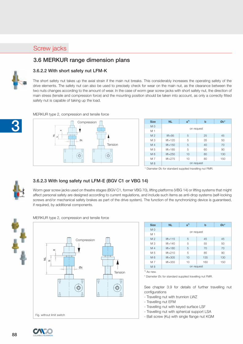
3.6.2.3 With long safety nut LFM-E (BGV C1 or VBG 14)
Worm gear screw jacks used on theatre stages (BGV C1, former VBG 70), lifting platforms (VBG 14) or lifting systems that might affect personal safety are de signed according to current regulations, and include such items as anti-drop systems (self-locking screws and/or mechanical safety brakes as part of the drive system). The function of the synchro nizing device is guaranteed, if re quired, by additional components.
MERKUR type 2, compression and tensile force
See chapter 3.9 for details of further travelling nut configurations- Travelling nut with trunnion LWZ- Travelling nut EFM- Travelling nut with keyed surface LSF- Travelling nut with spherical support LSA- Ball screw (Ku) with single flange nut KGM
1) As new.
* Diameter Øc for standard supplied travelling nut FMR.
Size NL a1) b Øc*
M 0
M 1
M 2 lift+115 5 45 45
M 3 lift+140 5 55 50
M 4 lift+180 5 70 70
M 5 lift+210 5 85 90
M 6 lift+305 10 135 130
M 7 lift+355 10 160 150
M 8 on request
on request
3.6 MERKUR range dimension plans
3.6.2.2 With short safety nut LFM-K
The short safety nut takes up the axial strain if the main nut breaks. This considerably increases the operating safety of the drive elements. The safety nut can also be used to precisely check for wear on the main nut, as the clearance between the two nuts changes according to the amount of wear. In the case of worm gear screw jacks with short safety nut, the direction of main stress (tensile and compression force) and the mounting position should be tak en into account, as only a correctly fitted safety nut is capable of taking up the load.
MERKUR type 2, compression and tensile force
Tension
Compression Size NL a1) b Øc*
M 0
M 1
M 2 lift+95 5 25 45
M 3 lift+120 5 35 50
M 4 lift+150 5 40 70
M 5 lift+185 5 60 90
M 6 lift+250 10 80 130
M 7 lift+275 10 80 150
M 8
on request
on request
* Diameter Øc for standard supplied travelling nut FMR.
Screw jacks
Compression
Tension
Fig. without limit switch