Embed Size (px)
Citation preview
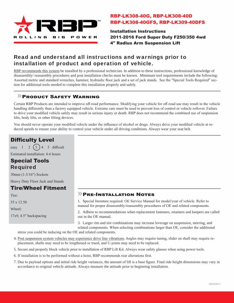
Read and understand all instructions and warnings prior to installation of product and operation of vehicle.RBP recommends this system be installed by a professional technician. In addition to these instructions, professional knowledge of disassembly/ reassembly procedures and post installation checks must be known. Minimum tool requirements include the following: Assorted metric and standard wrenches, hammer, hydraulic floor jack and a set of jack stands. See the "Special Tools Required" sec-tion for additional tools needed to complete this installation properly and safely.
»Product Safety WarningCertain RBP Products are intended to improve off-road performance. Modifying your vehicle for off-road use may result in the vehicle handling differently than a factory equipped vehicle. Extreme care must be used to prevent loss of control or vehicle rollover. Failure to drive your modified vehicle safely may result in serious injury or death. RBP does not recommend the combined use of suspension lifts, body lifts, or other lifting devices.
You should never operate your modified vehicle under the influence of alcohol or drugs. Always drive your modified vehicle at re-duced speeds to ensure your ability to control your vehicle under all driving conditions. Always wear your seat belt.
»Pre-Installation Notes1. Special literature required: OE Service Manual for model/year of vehicle. Refer tomanual for proper disassembly/reassembly procedures of OE and related components.2. Adhere to recommendations when replacement fasteners, retainers and keepers are calledout in the OE manual.3. Larger rim and tire combinations may increase leverage on suspension, steering, andrelated components. When selecting combinations larger than OE, consider the additional
stress you could be inducing on the OE and related components.4. Post suspension system vehicles may experience drive line vibrations. Angles may require tuning, slider on shaft may require re-
placement, shafts may need to be lengthened or trued, and U-joints may need to be replaced.5. Secure and properly block vehicle prior to installation of RBP Lift Kit. Always wear safety glasses when using power tools.6. If installation is to be performed without a hoist, RBP recommends rear alterations first.7. Due to payload options and initial ride height variances, the amount of lift is a base figure. Final ride height dimensions may vary in
accordance to original vehicle attitude. Always measure the attitude prior to beginning installation.
RBP020917
RBP-LK308-40G, RBP-LK308-40DRBP-LK308-40GFS, RBP-LK309-40DFS
Installation Instructions2011-2016 Ford Super Duty F250/350 4wd4" Radius Arm Suspension Lift
Difficulty Leveleasy 1 2 3 4 5 difficult
Estimated installation: 4-6 hours
Special Tools Required30mm (1-3/16") Sockets
Heavy Duty Floor Jack and Stands
Tire/Wheel FitmentTire:
35 x 12.50
Wheel:
17x9, 4.5" backspacing

RBP-LK308-40 Installation - pg. 2
INSTALLATION INSTRUCTION
»Pre-installation Notes1. These vehicles, especially diesel models, are very heavy. Be sure that proper
jacks/stands are used that are rated to handle the weight of the vehicle. Ensurethat the vehicle is well supported before beginning the installation.
2. The factory front track bar bolt requires 405 ft-lbs of torque to be installedproperly. Be sure you have the means of removing and installing this hardwareproperly. It is possible to install the hardware and torque to a more modestrange (200 ft-lbs or so) and take the vehicle to a shop with the means to torquethe hardware properly immediately after the installation is complete.
3. As a result of the location of the long radius arm suspension, support locationsare limited. Use your best judgment while supporting the vehicle with sufficientstrength stands at appropriate locations. The radius arms will need to movefreely during this installation.
»Front Installation1. Park the vehicle on a clean, flat surface and block the rear wheels for safety.
2. Raise the front of the vehicle and proper support with jack stands under theframe rails - See Pre-Installation Note 3.
3. Remove the front wheels.
4. Support the front axle with a hydraulic jack.
5. Remove the track bar ball joint nut at the axle. Figure 1 Thread the nut back on acouple of turns. Raise the axle a couple of inches with the jack. Place anappropriate sized pry bar between the axle mount and the track bar. Figure 2Lower the axle to pinch the pry bar between the track bar and axle mount. Takeyour hands off of the pry bar. Continue lowering the axle until the track barunseats from the taper. Remove the nut and track bar from the ball joint. Savenut.
Step 5 NoteIf the taper does not release, try using a larger diameter pry bar. A loud pop will be heard when the taper releases. If available, a correct sized tie rod end tool can also be used to unseat the taper.
Important—measure before starting!Measure from the center of the wheel up to the bottom edge of the wheel opening
LF__________ RF__________
LR__________ RR__________
Kit ContentsQty Part2 Front Coil Spring1 Front Track Bar2 Front Track Bar Bushing1 Front Track Bar Sleeve2 Radius Arm4 Radius Arm Bushing2 Radius Arm Sleeve2 Grease Fitting2 18mm Lock Nut4 3/4" SAE Washer
2 18mm-2.50 x 150mm bolt1 Sway Bar Drop (drv)1 Sway Bar Drop (pass)2 Bolt Pack - Sway Bar Drop2 Front Bump Stop Extension4 Zip Ties2 5" Rear Block2 Spring Plate4 5/8" x 3-5/8" x 15" U-bolts/nuts/washers
*Important* Verify you have all of the kit components before beginning installation.

RBP-LK308-40 Installation - pg. 3
Figure 1
Figure 2
6. Disconnect the track bar from the driver's side frame mount. Remove the trackbar from the vehicle. Save hardware.
7. Disconnect the front brake line brackets from the axle Figure 3. Save hardware.Remove the front axle hub vacuum lines retaining clips from the axle/radiusarm. Figure 4A,B
Figure 3

RBP-LK308-40 Installation - pg. 4
Figure 4A
Figure 4B
8. Remove the clips holding the front brake lines to the brackets on the frame.Figure 5A Using a proper line wrench, break loose the hard line at the junctionblock and rotate it 180 degrees. Figure 5B This will put the rubber line to thebottom. Tighten the hard line securely. Leave the brake line loose and save theretaining clip.
Figure 5A

RBP-LK308-40 Installation - pg. 5
Figure 5B
9. Disconnect the front sway bar from the frame. Swing the sway bar down andallow it to rest on the steering during the installation. Save frame mount hard-ware.
10. Remove the ABS brake lines from the retaining tabs on the radius arms.Figure 6A/B
Figure 6A
Figure 6B
11. Disconnect the steering drag link from the pitman arm. Remove the cotter pinand castellated nut cap. Remove the nut and thread back on by hand a couple

RBP-LK308-40 Installation - pg. 6
turns. Strike the end of the pitman arm near the drag link end to dislodge the taper from the pitman arm. Figure 7 Remove the nut and the drag link from the pitman arm. Save all hardware.
Figure 7
12. With the axle still well supported with a jack, disconnect the front shocks fromthe axle mounts. Leave the shocks attached to the frame, they will be used foradded axle support during the next portion of the installation. Save axle hard-ware.
13. Carefully lower the axle and remove the factory front springs. Take care notto over-extend any lines/hoses. Save the upper spring isolator to be reinstalledwith the new springs.
14. Reconnect the shocks to the axle with the original hardware. The shocks willhelp support the axle during the radius arm bracket installation.
15. Remove the factory bump stops from the retainer cups on the frame. Figure 8ARemove the bolt holding the retainer cup to the frame and remove from vehicle.Figure 8B
Figure 8A

RBP-LK308-40 Installation - pg. 7
Figure 8B
16. Reinstall the retainer cups on the frame along with the provided 3" tall bump stop spacers. Fasten with a provided 8mm x 100mm bolt and washer. Figure 9 Apply Loctite to the bolt and torque to 15 ft-lbs. Be sure the flat lip of the retainer cup is oriented out toward the coil spring. Reinstall the factory bump stop into the retainer cup.
Figure 9
17. Locate and loosen the four radius arm mounting bolts at the axle. Figure 10 Once again make sure that the axle is well supported by a jack.
Figure 10
Step 16 NoteThe bump stop extension hardware is located in hardware pack.
Step 17 NoteThe driver's side upper nut is welded to the radius arm.
RBP-LK308-40 Installation - pg. 8
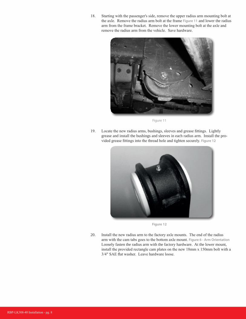
18. Starting with the passenger's side, remove the upper radius arm mounting bolt atthe axle. Remove the radius arm bolt at the frame Figure 11 and lower the radiusarm from the frame bracket. Remove the lower mounting bolt at the axle andremove the radius arm from the vehicle. Save hardware.
Figure 11
19. Locate the new radius arms, bushings, sleeves and grease fittings. Lightlygrease and install the bushings and sleeves in each radius arm. Install the pro-vided grease fittings into the thread hole and tighten securely. Figure 12
Figure 12
20. Install the new radius arm to the factory axle mounts. The end of the radiusarm with the cam tabs goes to the bottom axle mount. Figure 6 - Arm OrientationLoosely fasten the radius arm with the factory hardware. At the lower mount,install the provided rectangle cam plates on the new 18mm x 150mm bolt with a3/4" SAE flat washer. Leave hardware loose.

RBP-LK308-40 Installation - pg. 9
UP
Figure 13
21. If possible, attach the the new radius arm to the factory frame mount. It may benecessary to remove the driver's side radius arm first before attaching the pas-senger's side. Use the factory hardware and leave loose at this time.
22. Repeat install procedure on the driver's side. On some models, the upper mounton the driver's side factory radius arm will have a captive nut. If this is the case,use one of the left-over lower factory nuts. Use the provided 18mm nut and 3/4"SAE flat washer on the new 18mm bolt along with the provided cam washers.
23. With both sides completely installed and loosely fastened, position the rect-angle cam plates properly from the amount of lift on the vehicle. For liftheights of 4" or less the cam should be positioned back, so that the bolt is offsetcloser to the rear of the vehicle. For lift heights of 6" or more the cam shouldbe positioned forward, so that the bolt is offset closer to the front of the ve-hicle. Figure 14A/B - Cam position
Figure 14A - 4" Lift

RBP-LK308-40 Installation - pg. 10
Figure 14B - 6" Lift
24. With the hardware install complete, go back and torque all 6 radius arm bolts to220 ft-lbs.
25. If removed/loosened, reconnect the shocks to the axle mounts and torque hard-ware to 95 ft-lbs.
26. Attach the ABS wires to the new radius arms using the provided mountable zipties installed into the small holes located in the top of the radius arms. Figure 15Tighten securely and cut off access zip tie material.
Figure 15
27. With the axle still well supported, disconnect the shocks from the axle andframe. Save the axle mount hardware.
28. Lower the axle just enough to install the new coil springs along with the factoryupper rubber isolator. Once installed, rotate the coil so it seats properly in theaxle mount. Raise the axle until the coil is seated in the upper mount.
29. Locate the new provided shocks, bushings and sleeves. Each shock is suppliedwith a short and a long bushing/sleeve set. Identify the bushings and sleeves.The longer bushing/sleeve installs in the BODY end of the shock. Lightlygrease and install the bushings/sleeves in the correct locations.
30. Locate the provided upper shock mount brackets. Install the bracket on theROD end of the front shocks with the provided 1/2" hardware. Torque hardwareto 60 ft-lbs.
Step 30 NoteThe suspension will have to be com-pressed slightly to attach the shocks.

RBP-LK308-40 Installation - pg. 11
31. Locate the new front shocks, bushings and sleeves. Install the bushings andsleeves into the shock eyes. Install the shocks using the factory lower hardwareand provided stem hardware.
32. Torque shock hardware at axle to 100 ft-lbs. Tighten stem hardware until bush-ings deform.
33. Locate the new sway bar drop brackets. Install the brackets on the frame withthe original sway bar mount hardware. When installed the brackets should off-set toward the front of the vehicle and the open face point to the inside. Figure 17Leave hardware loose.
Figure 17
34. Attach the sway bar to the new drop brackets with the provided 3/8" hardware.Torque the factory hardware and new 3/8" hardware to 30 ft-lbs.
35. Reattach all vacuum lines. Use the provided zip ties where needed.
36. Remove the factory front brake line brackets from the frame. The brackets havea squared edge in the brake line mounting hole. Figure 18A Using a file or rotarygrinder, remove the square edge to form a complete round hole. Figure 18B Reat-tach the brackets to the frame tighten securely with the factory hardware. Installthe brake line junction in the bracket from the bottom and fasten with the factoryretaining clip. Figure 18C
Figure 18A
Step 33 NoteSway bar drop hardware is located in hardware pack.

RBP-LK308-40 Installation - pg. 12
Figure 18B
Figure 18C
37. Properly bleed the brake system of air and top off the brake fluid reservoir withthe proper type of fluid (see owners manual).
38. Reattach the steering drag link to the pitman arm. Torque nut to 148 ft-lbs.Install the original castellated nut cap and new 1/8" cotter pin.
39. Locate the provided new front track bar, track bar bushings and sleeve. Lightlygrease and install the bushings and sleeve into the track bar.
40. Attach the new assembled front track bar to the original ball joint mount of thepassenger's side of the axle. Figure 19 Fasten with the factory nut and torqueto 184 ft-lbs. The frame end will be attached with the vehicle's weight on thesuspension.
Figure 19
Step 37 NoteNew cotter pin is located in hardware pack.

RBP-LK308-40 Installation - pg. 13
41. Install the front wheels and lower the vehicle to the ground. Torque lug nuts to165 ft-lbs.
42. Bounce the front of the vehicle to settle the suspension. Torque all factoryradius arm hardware to 220 ft-lbs.
43. Install the new track bar into the factory frame bracket. Figure 20 Lightly greasethe faces of the bushings to ease installation. Fasten with the factory hardwareand torque to 405 ft-lbs.
Figure 20
44. Check all hardware for proper torque.
»Rear Installation1. Block the front wheels for safety.
2. Raise the rear of the vehicle and support with jack stands under the frame railsjust ahead of the spring hangers.
3. Remove the wheels.
4. Support the axle with a hydraulic jack.
5. Remove the factory shocks. Retain all mounting hardware.
6. Disconnect the passenger’s side spring u-bolts. Using two C-Clamps, clamp theleaf spring on each side of the top u-bolt plate. Figure 21 Remove the center pinnut and remove the u-bolt plate. Reinstall the center pin nut and torque to 40ft-lbs. The u-bolts, top plate and bottom plate will not be reused.
Step 42 NoteSee pre-installation note #2.
The track bar end should fit tight into the bracket. If necessary, use a heavy rubber dead-blow rubber hammer to help align the end into the bracket.
Step 5 NoteThe factory rear block will vary depending on the vehicle model. F-250s will have a 1-7/8" block and F-350s will have a 3-3/4" block. In both cases, replacing the fac-tory block with the new provided block will net the same level stance regardless of vehicle model.
RBP-LK308-40 Installation - pg. 14
Figure 21
7. Remove the factory lift block. It will not be reused.
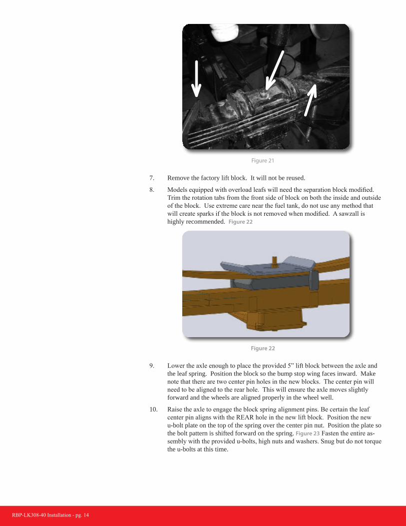
8. Models equipped with overload leafs will need the separation block modified.Trim the rotation tabs from the front side of block on both the inside and outsideof the block. Use extreme care near the fuel tank, do not use any method thatwill create sparks if the block is not removed when modified. A sawzall ishighly recommended. Figure 22
Figure 22
9. Lower the axle enough to place the provided 5” lift block between the axle andthe leaf spring. Position the block so the bump stop wing faces inward. Makenote that there are two center pin holes in the new blocks. The center pin willneed to be aligned to the rear hole. This will ensure the axle moves slightlyforward and the wheels are aligned properly in the wheel well.
10. Raise the axle to engage the block spring alignment pins. Be certain the leafcenter pin aligns with the REAR hole in the new lift block. Position the newu-bolt plate on the top of the spring over the center pin nut. Position the plate sothe bolt pattern is shifted forward on the spring. Figure 23 Fasten the entire as-sembly with the provided u-bolts, high nuts and washers. Snug but do not torquethe u-bolts at this time.

RBP-LK308-40 Installation - pg. 15
FRONT
Figure 23
11. Repeat block installation of the driver’s side. Take care not to over extend thebrake lines. Note: The parking brake cable bracket will need to be removed fromthe spring center pin. Figure 24
Figure 24
12. If more parking brake cable slack is needed, remove the cable from the rear-most retaining bracket on the frame. Figure 25

RBP-LK308-40 Installation - pg. 16
Figure 25
13. The brakelines may require additional slack. Located the factory bracket on theaxle. Using an adjustable wrench, carefully bend the bracket so the fittings arepositioned vertical to allow more slack. Figure 26
Figure 26
14. Install the new shocks with the original mounting hardware.
15. Install wheels and lower the vehicle to the ground.
16. With the weight of the vehicle on the axle, torque the u-bolts to 130-150 ft-lbs.
»Post Installation1. Check all hardware for proper torque. Check hardware after 500 miles.
2. Be sure the brake system has been properly bled and the brake fluid is topped off.
3. The steering wheel will need to be re-centered. This is done by adjusting thedrag link collar near the passenger's side steering knuckle. Torque clamps to 41ft-lbs. Thread the collar to lengthen the drag link.
4. Adjust headlights.
Post-Installation Warnings1. Check all fasteners for propertorque. Check to ensure for adequate clearance between all rotating, mobile, fixed, and heated members. Verify clearance between exhaust and brake lines, fuel lines, fuel tank, floor boards and wiring harness. Check steering gear for clearance. Test and inspect brake system.
2. Perform steering sweep to ensurefront brake hoses have adequate slack and do not contact any rotating, mobile or heated members. Inspect rear brake hoses at full extension for adequate slack. Failure to perform hose check/ replacement may result in component failure.
3. Perform head light check andadjustment.
4. Re-torque all fasteners after 500miles. Always inspect fasteners and components during routine servicing.