Embed Size (px)
Citation preview
15 Gallon Liquid Applicator15 Gallon Liquid ApplicatorModel BA15, BA15KOwner's Manual
PBZ LLC | 50 Woodcorner Rd. | Lititz PA 17543www.CropCareEquipment.com | (717) 738-7365
A Paul B Zimmerman Inc. Company

Thank you for choosing to purchase one of our liquid applicator models. We appreciate your business and want to personally fill all of your sprayer needs. We also desire to provide you with the technical support and needed parts that will allow you to continue operation without disruption. See the Contact Us section on page 18.
Table of ContentsBefore You Begin..............................................................................................................................1Safety Precautions............................................................................................................................2
General Guidelines....................................................................................................................2Before Operation.......................................................................................................................2During Operation.......................................................................................................................3Pump Safety Precautions...........................................................................................................3
Mounting the Applicator.................................................................................................................4Applicator Unit..........................................................................................................................4Applicator Spray Nozzles..........................................................................................................5Wiring Harness..........................................................................................................................6
Calibrating the Applicator..............................................................................................................7Calibration Chart.......................................................................................................................8
Operating Instructions....................................................................................................................9Before Operation.......................................................................................................................9During Operation.......................................................................................................................9Following Operation..................................................................................................................9
Maintenance Instructions................................................................................................................10Routine Maintenance.................................................................................................................10Winterizing Your Applicator.....................................................................................................10
Troubleshooting.................................................................................................................................11Warranty............................................................................................................................................12Liquid Applicator Breakdown........................................................................................................13
Applicator Unit Parts List..........................................................................................................14Application Kit Parts List..........................................................................................................14
Pump Breakdown...............................................................................................................................15Relief Valve Breakdown....................................................................................................................16Accessories........................................................................................................................................17Contact Us.........................................................................................................................................18
Before You Begin Please read and understand this manual and its instructions and warnings
completely before operating the liquid applicator. If you purchased model BA15, the spray nozzles, spray hose, nozzle bodies, and boom clamps aren't included.
Be aware of all safety guidelines, warnings, and cautions including those of any piece of equipment the liquid applicator may be mounted upon or used with accordingly.
Read and understand the inoculant or chemical manufacturer's labels, warnings, and instructions.
Page 1
! Safety Precautions !General Guidelines
Every year many unnecessary accidents occur due to improper equipment handling and a disregard for safety precautions. You, the operator, can avoid accidents by observing the precautions in this section.
NEVER MOUNT, FILL, OR SERVICE THE LIQUID APPLICATOR WHEN THE EQUIPMENT IS RUNNING. Always turn the equipment off, the tractor off, and unhook the piece of equipment before mounting, filling, or servicing.
The operator should be a responsible adult. Do not allow persons to operate this liquid applicator until they have displayed a thorough understanding of applicator safety precautions and operational use!
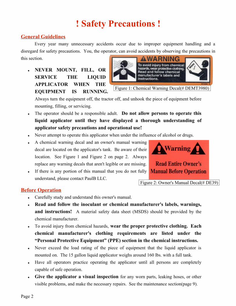
Never attempt to operate this applicator when under the influence of alcohol or drugs. A chemical warning decal and an owner's manual warning
decal are located on the applicator's tank. Be aware of their location. See Figure 1 and Figure 2 on page 2. Always replace any warning decals that aren't legible or are missing.
If there is any portion of this manual that you do not fully understand, please contact PaulB LLC.
Before Operation Carefully study and understand this owner's manual. Read and follow the inoculant or chemical manufacturer's labels, warnings,
and instructions! A material safety data sheet (MSDS) should be provided by the chemical manufacturer.
To avoid injury from chemical hazards, wear the proper protective clothing. Each chemical manufacturer's clothing requirements are listed under the “Personal Protective Equipment” (PPE) section in the chemical instructions.
Never exceed the load rating of the piece of equipment that the liquid applicator is mounted on. The 15 gallon liquid applicator weighs around 160 lbs. with a full tank.
Have all operators practice operating the applicator until all persons are completely capable of safe operation.
Give the applicator a visual inspection for any worn parts, leaking hoses, or other visible problems, and make the necessary repairs. See the maintenance section(page 9).
Page 2
Figure 1: Chemical Warning Decal(# DEMT3980)
Figure 2: Owner's Manual Decal(# DE39)
During Operation NEVER MOUNT, FILL, OR SERVICE THE LIQUID APPLICATOR
WHEN THE EQUIPMENT IS RUNNING. Always turn the equipment off, the tractor off, and unhook the piece of equipment before mounting, filling, or servicing.
Always be aware of bystanders, particularly children! No passengers are allowed on the mounting equipment or the applicator at anytime. Never leave running equipment, including the liquid applicator, unattended! Remember that accidents can even happen to seasoned operators. Always take your time
and follow all safety instructions. When you are finished using the applicator, always remember to rinse the tank and flush
the pump of all harmful chemical residue. Store the applicator in an area protected from the elements. Do not permit children to play on or around the applicator.
Pump Safety Precautions Never pump flammable, explosive, petroleum-based, or any other non-compatible
products such as gasoline, fuel oil, kerosene, etc. Such practices will void the manufacturer's warranty.
DO NOT allow the pump to get wet or to be exposed to the elements. Allowing the pump to get wet or to be exposed to the elements voids the manufacturer's warranty.
Note: The pump may be run dry for limited periods without resulting in damage. Never attempt to adjust the pressure of the pump. Any unapproved pump adjustment will
void the manufacturer's warranty. Always disconnect the power to the pump when working on the pump. Failure to do this
could result in electrical shock.
Page 3
Mounting the ApplicatorThis liquid applicator is designed to be mounted on a baler, forage harvester, bagger, blower, and
any other applicable piece of equipment. Mounting the liquid applicator correctly and securely will ensure consistent and safe operation.
Applicator Unit
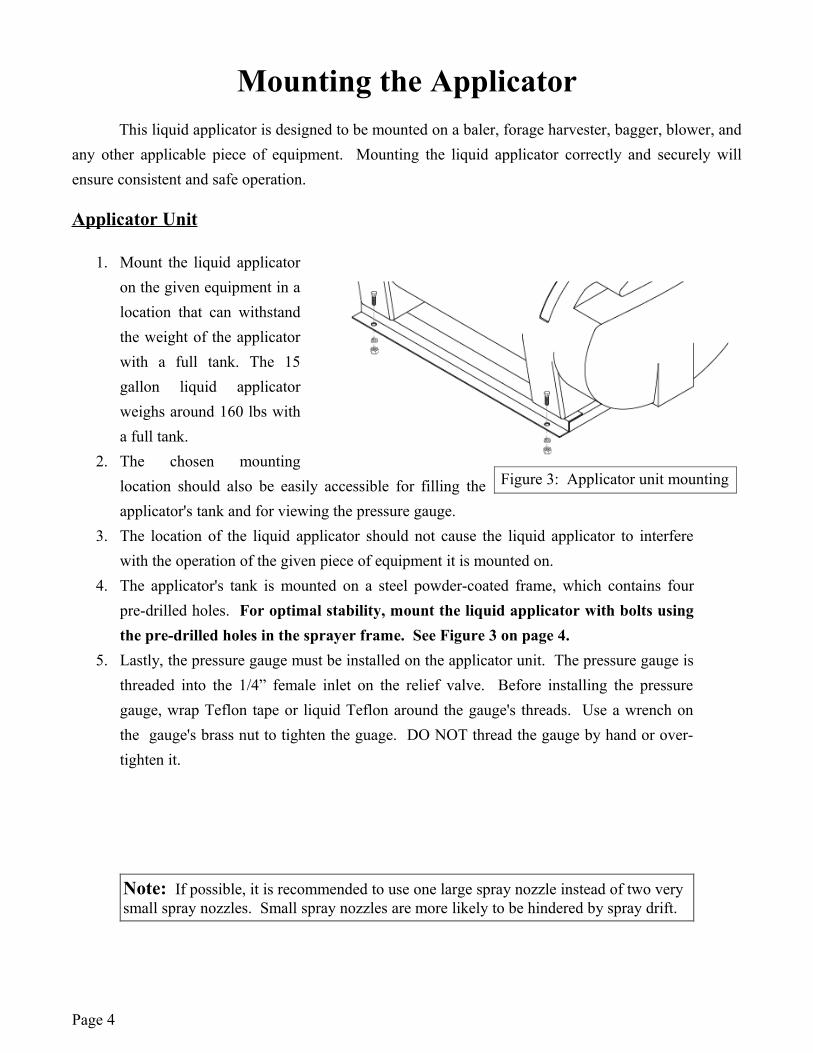
1. Mount the liquid applicator on the given equipment in a location that can withstand the weight of the applicator with a full tank. The 15 gallon liquid applicator weighs around 160 lbs with a full tank.
2. The chosen mounting location should also be easily accessible for filling the applicator's tank and for viewing the pressure gauge.
3. The location of the liquid applicator should not cause the liquid applicator to interfere with the operation of the given piece of equipment it is mounted on.
4. The applicator's tank is mounted on a steel powder-coated frame, which contains four pre-drilled holes. For optimal stability, mount the liquid applicator with bolts using the pre-drilled holes in the sprayer frame. See Figure 3 on page 4.
5. Lastly, the pressure gauge must be installed on the applicator unit. The pressure gauge is threaded into the 1/4” female inlet on the relief valve. Before installing the pressure gauge, wrap Teflon tape or liquid Teflon around the gauge's threads. Use a wrench on the gauge's brass nut to tighten the guage. DO NOT thread the gauge by hand or over- tighten it.
Page 4
Figure 3: Applicator unit mounting
Note: If possible, it is recommended to use one large spray nozzle instead of two very small spray nozzles. Small spray nozzles are more likely to be hindered by spray drift.
Applicator Spray NozzlesWith the liquid applicator securely mounted, you now need to properly mount the spray
nozzle(s) in the desired location. Mounting technique may vary with the piece of equipment being used.
1. Determine the optimal location for applying the liquid inoculant or other chemicals. Ensure that this location will provide complete coverage and safe operation.
2. Attach the vinyl spray hose to the discharge barb with an included hose clamp. Route the vinyl hose to the desired application location on the piece of equipment. Ensure that the hose will not interfere with the operation of the equipment.
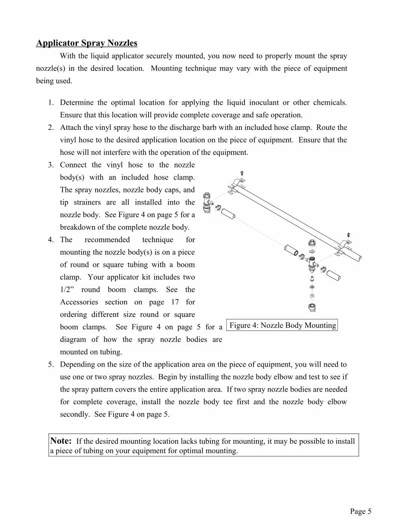
3. Connect the vinyl hose to the nozzle body(s) with an included hose clamp. The spray nozzles, nozzle body caps, and tip strainers are all installed into the nozzle body. See Figure 4 on page 5 for a breakdown of the complete nozzle body.
4. The recommended technique for mounting the nozzle body(s) is on a piece of round or square tubing with a boom clamp. Your applicator kit includes two 1/2” round boom clamps. See the Accessories section on page 17 for ordering different size round or square boom clamps. See Figure 4 on page 5 for a diagram of how the spray nozzle bodies are mounted on tubing.
5. Depending on the size of the application area on the piece of equipment, you will need to use one or two spray nozzles. Begin by installing the nozzle body elbow and test to see if the spray pattern covers the entire application area. If two spray nozzle bodies are needed for complete coverage, install the nozzle body tee first and the nozzle body elbow secondly. See Figure 4 on page 5.
Page 5
Figure 4: Nozzle Body Mounting
Note: If the desired mounting location lacks tubing for mounting, it may be possible to install a piece of tubing on your equipment for optimal mounting.
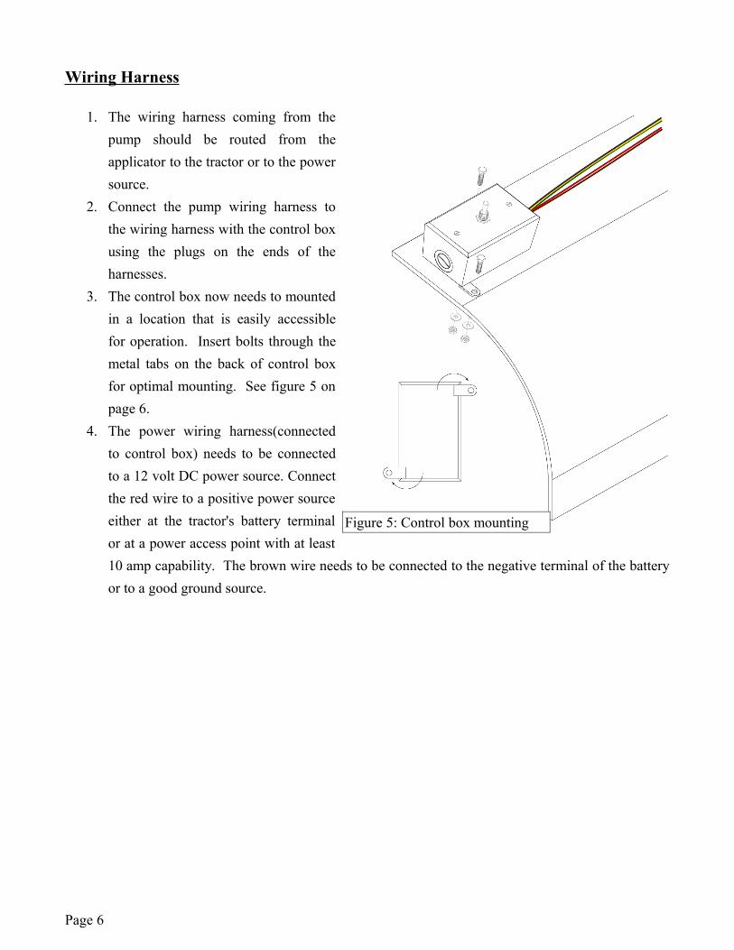
Wiring Harness
1. The wiring harness coming from the pump should be routed from the applicator to the tractor or to the power source.
2. Connect the pump wiring harness to the wiring harness with the control box using the plugs on the ends of the harnesses.
3. The control box now needs to mounted in a location that is easily accessible for operation. Insert bolts through the metal tabs on the back of control box for optimal mounting. See figure 5 on page 6.
4. The power wiring harness(connected to control box) needs to be connected to a 12 volt DC power source. Connect the red wire to a positive power source either at the tractor's battery terminal or at a power access point with at least 10 amp capability. The brown wire needs to be connected to the negative terminal of the battery or to a good ground source.
Page 6
Figure 5: Control box mounting
Calibrating the ApplicatorTo ensure accurate and complete coverage, the liquid applicator must be calibrated to determine
the correct spray nozzle size and pressure setting. The calibration process is simplified when broken up into the following three steps:
1. Determine the gallon per ton (gpt) recommendation of the inoculant/chemical manufacturer.
2. Determine the minute per ton(mpt) rating of the crop through the given piece of equipment.
3. Use the calibration formula to determine the necessary nozzle and pressure setting.
Determine the gallon per ton recommendation.
The inoculant/chemical manufacturer should provide instructions that detail how many gallons per ton(gpt) should be applied for various crops. This amount will likely vary depending on what crop you are applying the inoculant or chemical to.
2. Determine the minute per ton(mpt) rating of the crop through your piece of equipment.
You now need to calculate the minute per ton(mpt) rating or simply the number of minutes it takes for one ton of crop to be processed by the piece of equipment you are using the liquid applicator on.
Example: Your baler can bale a 2.5 ton load in 25 minutes. The minute per ton rating would be 10 minutes per ton(25 min/2.5ton=12mpt)
3. Use the calibration formula to determine the optimal spray nozzle and pressure setting.
1. Determine the necessary gallons per minute(gpm) per nozzle. The calibration formula is gallons per minute(gpm) = gallon per ton(gpt) / minute per ton. Use the gallons per ton(gpt) and the minutes per ton(mpt) found in steps 1-2 to determine the gallons per minute using the formula.
Example: Assume the gpt recommendation is .25 gallons or inoculant per ton of silage and your blower processes a ton of silage every 2 minutes. Using the formula, you would find that you need a flow rate of .125 gpm (.25 gpt / 2 mpt) per nozzle.
Page 7
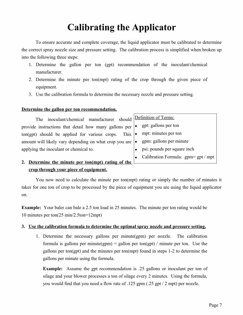
Definition of Terms:
● gpt: gallons per ton
● mpt: minutes per ton
● gpm: gallons per minute
● psi: pounds per square inch
● Calibration Formula: gpm= gpt / mpt
2. Using the gallons per minute calculation, use the calibration chart on page 8 to determine correct spray nozzle size and pressure setting.
Example: Suppose you calculated your necessary gallons per minute to be .20, you should to use the yellow XR11002VP nozzle and set the pump's pressure at 40 psi using the relief valve.
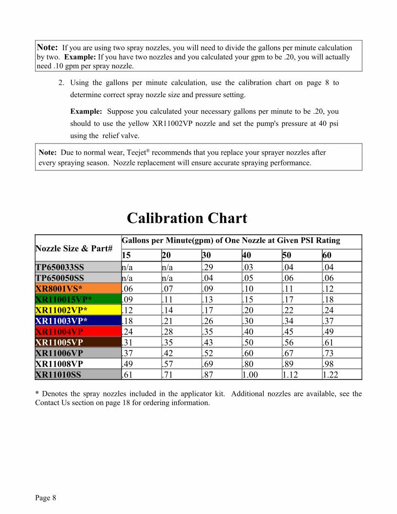
Calibration Chart
Nozzle Size & Part#Gallons per Minute(gpm) of One Nozzle at Given PSI Rating
15 20 30 40 50 60TP650033SS n/a n/a .29 .03 .04 .04TP650050SS n/a n/a .04 .05 .06 .06XR8001VS* .06 .07 .09 .10 .11 .12XR110015VP* .09 .11 .13 .15 .17 .18XR11002VP* .12 .14 .17 .20 .22 .24XR11003VP* .18 .21 .26 .30 .34 .37XR11004VP .24 .28 .35 .40 .45 .49XR11005VP .31 .35 .43 .50 .56 .61XR11006VP .37 .42 .52 .60 .67 .73XR11008VP .49 .57 .69 .80 .89 .98XR11010SS .61 .71 .87 1.00 1.12 1.22
* Denotes the spray nozzles included in the applicator kit. Additional nozzles are available, see the Contact Us section on page 18 for ordering information.
Page 8
Note: If you are using two spray nozzles, you will need to divide the gallons per minute calculation by two. Example: If you have two nozzles and you calculated your gpm to be .20, you will actually need .10 gpm per spray nozzle.
Note: Due to normal wear, Teejet® recommends that you replace your sprayer nozzles after every spraying season. Nozzle replacement will ensure accurate spraying performance.
Operating InstructionsBefore operating your liquid applicator, it is important that you read this entire manual and know
all safety precautions. Always take your time and be alert when operating your applicator. This will allow you to safely operate the unit without accident or interruption.
Before Operation:
1. Before operation it is important to give the applicator unit a thorough inspection, covering the hoses, wiring harness, and other applicator components. Ensure that the suction strainer and the tank are rinsed out.
2. Calibrate the liquid applicator for the given conditions following the directions listed in the Calibrating section on page 6. Install the correct spray nozzle(s) on the applicator.
3. Before using any inoculant or chemical ensure that it isn't a petroleum-based product or a non-compatible chemical for the pump. Using petroleum-based products or non-compatible chemicals voids the manufacturer's warranty. If you are unsure of the acceptableness of a chemical or substance, contact PaulB LLC.
4. Connect the power wiring harness to an approved 12 volt power source as described in the Mounting the Applicator section on page 4.
During Operation
1. Fill the applicator tank with the correct amount of water and inoculant as instructed by the manufacturer of the inoculant being used.
2. Turn on the pump using the control switch and set the pressure by turning the relief valve. The pressure should be set to the optimal rate found when you calibrated the liquid applicator.
3. When you are finished using the applicator, turn the control switch to off. If the applicator's tank becomes empty, remember to turn the control switch to off.
Following Operation:
1. Thoroughly rinsing the applicator of any chemical residue is an important activity. It is recommended to fill the tank with fresh water and engage the pump until the system is entirely free of chemical residue. It is important not to rinse the applicator in an area where humans, animals, or sensitive plants could come in contact with chemical residue.
2. Store the applicator in a location where it will be away from human or animal activity. Do not allow children to play on or near the applicator.
Page 9
Maintenance InstructionsRoutine Maintenance
It is very important to perform routine maintenance on your liquid applicator before and after each use. Good maintenance practices will help to guard against any unnecessary applicator breakdowns or accidents.
1. It is recommended to perform a visual and physical inspection for any worn parts, damaged hoses, or other visible problems. Make all necessary repairs before operation. See the Contact Us section on page 18 for parts ordering instructions.
2. After each use it is important to rinse the pump and all components by running water through the system. Fill the tank with a sufficient amount of fresh water and engage the pump. Rinsing the pump with fresh water will greatly improve the life of the pump!
3. The suction strainer should be taken out and rinsed regularly. 4. Always follow all pump safety precautions and warnings (page 3). Following these
guidelines will help to ensure many years of smooth and trouble-free pumping.
Winterizing Your Applicator
To avoid damage from freezing and corrosion, it is important to winterize your applicator before temperatures grow too cold. Failure to winterize your applicator will void the manufacturer's warranty.
1. Verify that the tank is empty and rinsed out. Dump a ½ gallon of RV nontoxic antifreeze into the tank. It is not recommended to use standard Antifreeze. Standard antifreeze can be harmful to humans, animals, crops, and the environment.
2. Engage the pump for several minutes. Ensure that the antifreeze has been pumped through the entire system.
3. Store the applicator in a dry location away from the elements.4. Before operation in the spring it is recommended to flush the applicator with fresh water
to cleanse it of the antifreeze and any other buildup. It would also be beneficial to do a thorough inspection of all the applicator's components before operation.
Page 10
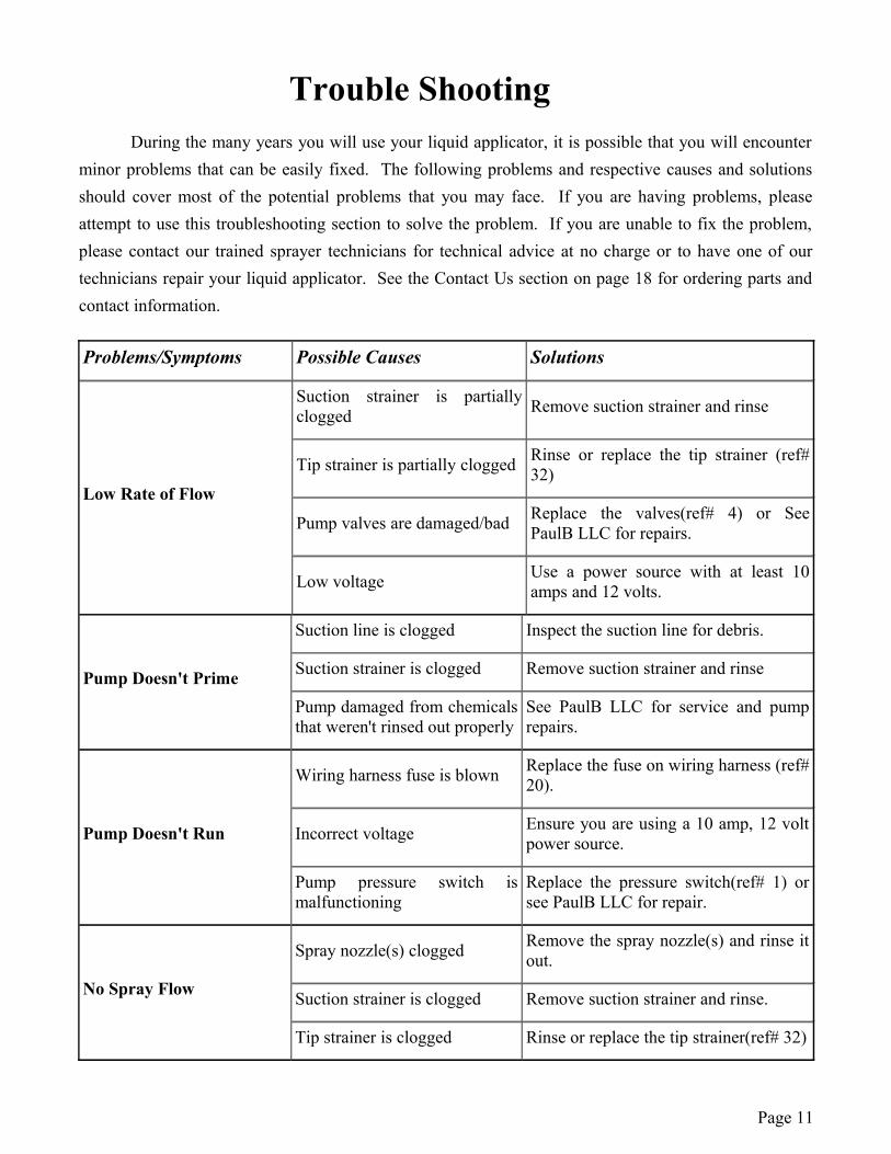
Trouble ShootingDuring the many years you will use your liquid applicator, it is possible that you will encounter
minor problems that can be easily fixed. The following problems and respective causes and solutions should cover most of the potential problems that you may face. If you are having problems, please attempt to use this troubleshooting section to solve the problem. If you are unable to fix the problem, please contact our trained sprayer technicians for technical advice at no charge or to have one of our technicians repair your liquid applicator. See the Contact Us section on page 18 for ordering parts and contact information.
Problems/Symptoms Possible Causes Solutions
Low Rate of Flow
Suction strainer is partially clogged Remove suction strainer and rinse
Tip strainer is partially clogged Rinse or replace the tip strainer (ref# 32)
Pump valves are damaged/bad Replace the valves(ref# 4) or See PaulB LLC for repairs.
Low voltage Use a power source with at least 10 amps and 12 volts.
Pump Doesn't Prime
Suction line is clogged Inspect the suction line for debris.
Suction strainer is clogged Remove suction strainer and rinse
Pump damaged from chemicals that weren't rinsed out properly
See PaulB LLC for service and pump repairs.
Pump Doesn't Run
Wiring harness fuse is blown Replace the fuse on wiring harness (ref# 20).
Incorrect voltage Ensure you are using a 10 amp, 12 volt power source.
Pump pressure switch is malfunctioning
Replace the pressure switch(ref# 1) or see PaulB LLC for repair.
No Spray Flow
Spray nozzle(s) clogged Remove the spray nozzle(s) and rinse it out.
Suction strainer is clogged Remove suction strainer and rinse.
Tip strainer is clogged Rinse or replace the tip strainer(ref# 32)
Page 11
PaulB LLC Limited Warranty15 Gallon Liquid Applicators
Models: BA15, BA15K
Warranty Coverage
PaulB LLC hereby provides a Limited One (1) Year Warranty on the 15 gallon liquid applicators, models BA15, BA15K, manufactured by PaulB LLC from the date of original purchase. Liquid applicators built by PaulB LLC are warrantied against any manufacturer's defects that may occur to any of the applicator's components in the 12 months following the original date of purchase. This warranty covers the purchaser of this liquid applicator and any other owners who own it during the one year warranty period. To retain the warranty, the liquid applicator must be operated and maintained as ascribed by its owner's manual.
Warranty is void if:
1. The liquid applicator has been subjected to, in the opinion of PaulB LLC, negligent handling, misuse, an accident or if the instructions in the owner's manual were not completely followed.
2. The liquid applicator's components have been altered in any manner or repairs have taken place with unapproved parts. Alterations include adjusting the pressure setting of the pump.
3. The liquid applicator and its components were subject to freezing or freezing conditions. The liquid applicator must have been winterized as per the maintenance instructions to retain the warranty.
4. The liquid applicator was powered by a power source other than a 10 amp, 12 volt DC power source.
5. A non-compatible chemical(including petroleum-based or flammable liquids) was used and/or if the applicator operator failed to rinse all chemical residue out of the applicator's components after use.
6. The pump was allowed to get wet repeatedly or was unprotected from the elements.
Getting Service
All liquid applicator warranty claims must be made through PaulB LLC. All warranty claims must be submitted with an invoice or a proof of purchase that denotes the purchase date and place. If you have any questions or comments concerning this warranty, please contact PaulB LLC.
Page 12
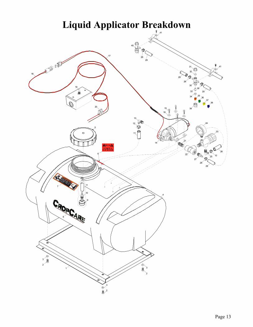
Liquid Applicator Breakdown
Page 13
25 12
26
3
2
4
41
21
5
24
23
3
2
3
2 1
14
39
34
33
30
28
2829
29
22
2728
29
11
12
13
15
32
31
40
16
7
19
41
17
18
20
3637
38
2928
35
11
10
9
6
8
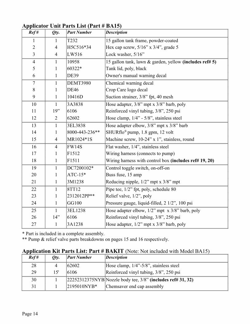
Applicator Unit Parts List (Part # BA15)Ref # Qty. Part Number Description
1 1 T232 15 gallon tank frame, powder-coated2 4 H5C516*34 Hex cap screw, 5/16” x 3/4”, grade 53 4 LW516 Lock washer, 5/16”4 1 10958 15 gallon tank, lawn & garden, yellow (includes ref# 5)5 1 60322* Tank lid, poly, black6 1 DE39 Owner's manual warning decal7 1 DEMT3980 Chemical warning decal8 1 DE46 Crop Care logo decal9 1 10416D Suction strainer, 3/8” fpt, 40 mesh10 1 3A3838 Hose adapter, 3/8” mpt x 3/8” barb, poly11 19” 6106 Reinforced vinyl tubing, 3/8”, 250 psi12 2 62602 Hose clamp, 1/4” - 5/8”, stainless steel13 1 3EL3838 Hose adapter elbow, 3/8” mpt x 3/8” barb14 1 8000-443-236** SHURflo® pump, 1.8 gpm, 12 volt15 4 MR1024*1S Machine screw, 10-24” x 1”, stainless, round16 4 FW14S Flat washer, 1/4”, stainless steel17 1 F1512 Wiring harness (connects to pump)18 1 F1511 Wiring harness with control box (includes ref# 19, 20)19 1 DC7200102* Control toggle switch, on-off-on20 1 ATC-15* Buss fuse, 15 amp21 1 3M1238 Reducing nipple, 1/2” mpt x 3/8” mpt22 1 8TT12 Pipe tee, 1/2” fpt, poly, schedule 8023 1 2312012PP** Relief valve, 1/2”, poly24 1 GG100 Pressure gauge, liquid-filled, 2 1/2”, 100 psi25 1 3EL1238 Hose adapter elbow, 1/2” mpt x 3/8” barb, poly26 14” 6106 Reinforced vinyl tubing, 3/8”, 250 psi27 1 3A1238 Hose adapter, 1/2” mpt x 3/8” barb, poly
* Part is included in a complete assembly.** Pump & relief valve parts breakdowns on pages 15 and 16 respectively.
Application Kit Parts List: Part # BAKIT (Note: Not included with Model BA15)Ref # Qty. Part Number Description
28 4 62602 Hose clamp, 1/4”-5/8”, stainless steel29 15' 6106 Reinforced vinyl tubing, 3/8”, 250 psi30 1 22252312375NYB Nozzle body tee, 3/8” (includes ref# 31, 32)31 1 2195010NYB* Chemsaver end cap assembly
Page 14
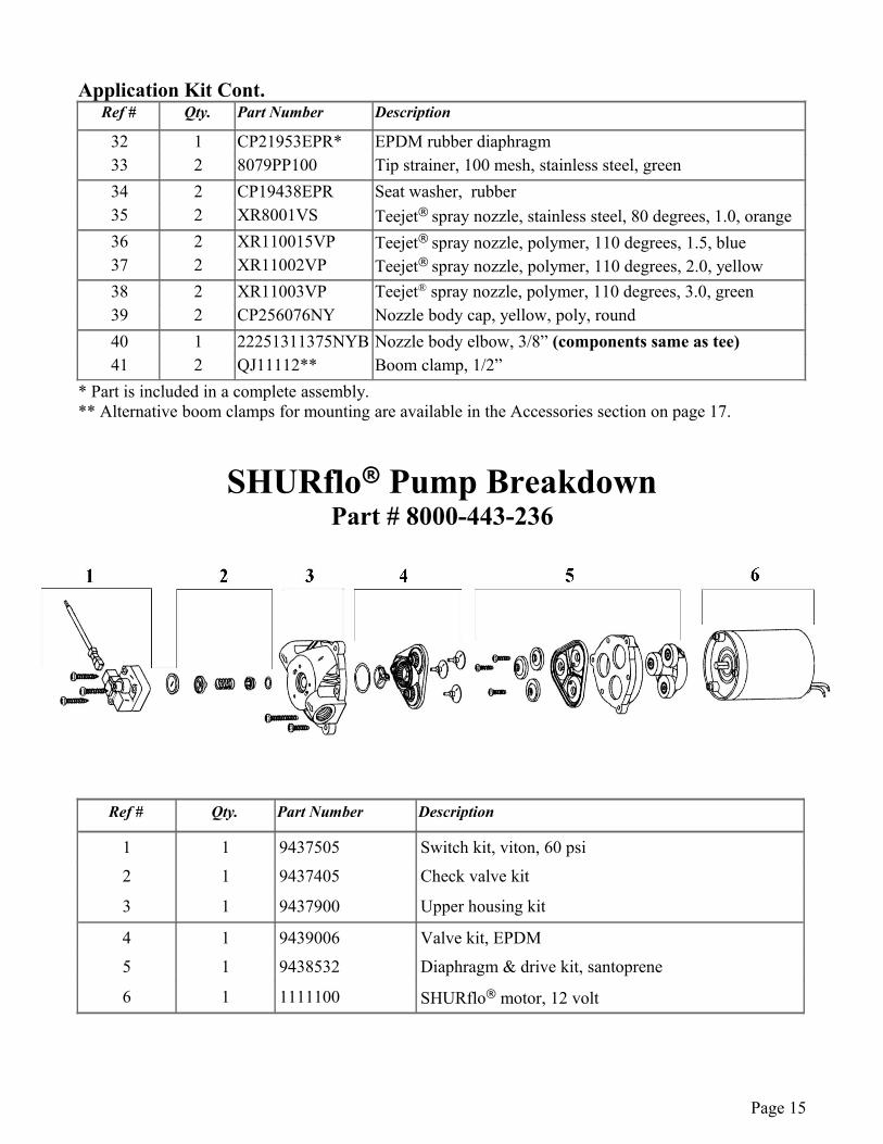
Application Kit Cont.Ref # Qty. Part Number Description
32 1 CP21953EPR* EPDM rubber diaphragm33 2 8079PP100 Tip strainer, 100 mesh, stainless steel, green34 2 CP19438EPR Seat washer, rubber35 2 XR8001VS Teejet® spray nozzle, stainless steel, 80 degrees, 1.0, orange36 2 XR110015VP Teejet® spray nozzle, polymer, 110 degrees, 1.5, blue37 2 XR11002VP Teejet® spray nozzle, polymer, 110 degrees, 2.0, yellow38 2 XR11003VP Teejet® spray nozzle, polymer, 110 degrees, 3.0, green39 2 CP256076NY Nozzle body cap, yellow, poly, round40 1 22251311375NYB Nozzle body elbow, 3/8” (components same as tee)41 2 QJ11112** Boom clamp, 1/2”
* Part is included in a complete assembly.** Alternative boom clamps for mounting are available in the Accessories section on page 17.
SHURflo® Pump BreakdownPart # 8000-443-236
Ref # Qty. Part Number Description
1 1 9437505 Switch kit, viton, 60 psi
2 1 9437405 Check valve kit
3 1 9437900 Upper housing kit
4 1 9439006 Valve kit, EPDM
5 1 9438532 Diaphragm & drive kit, santoprene
6 1 1111100 SHURflo® motor, 12 volt
Page 15
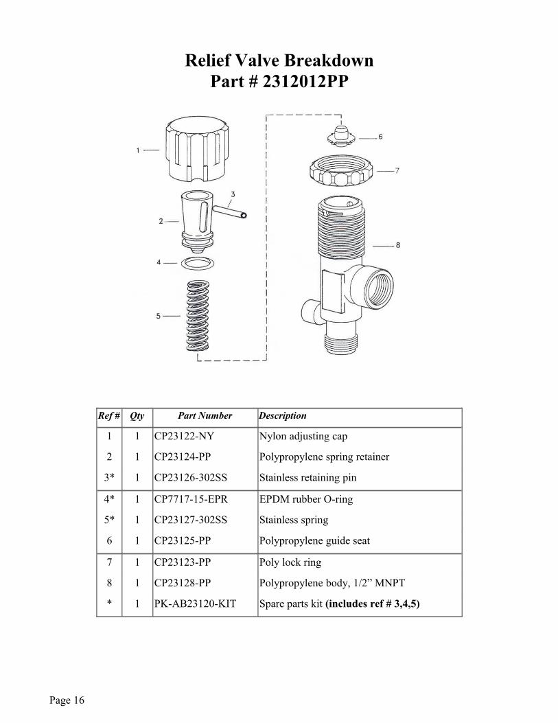
Relief Valve BreakdownPart # 2312012PP
Ref # Qty Part Number Description
1 1 CP23122-NY Nylon adjusting cap
2 1 CP23124-PP Polypropylene spring retainer
3* 1 CP23126-302SS Stainless retaining pin
4* 1 CP7717-15-EPR EPDM rubber O-ring
5* 1 CP23127-302SS Stainless spring
6 1 CP23125-PP Polypropylene guide seat
7 1 CP23123-PP Poly lock ring
8 1 CP23128-PP Polypropylene body, 1/2” MNPT
* 1 PK-AB23120-KIT Spare parts kit (includes ref # 3,4,5)
Page 16
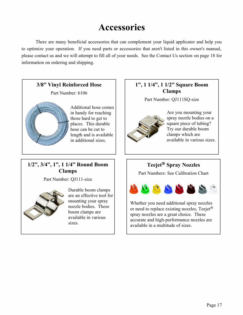
AccessoriesThere are many beneficial accessories that can complement your liquid applicator and help you
to optimize your operation. If you need parts or accessories that aren't listed in this owner's manual, please contact us and we will attempt to fill all of your needs. See the Contact Us section on page 18 for information on ordering and shipping.
Page 17
1”, 1 1/4”, 1 1/2” Square Boom Clamps
Part Number: QJ111SQ-size
Are you mounting your spray nozzle bodies on a square piece of tubing? Try our durable boom clamps which are available in various sizes.
3/8” Vinyl Reinforced HosePart Number: 6106
Additional hose comes in handy for reaching those hard to get to places. This durable hose can be cut to length and is available in additional sizes.
1/2”, 3/4”, 1”, 1 1/4” Round Boom Clamps
Part Number: QJ111-size
Durable boom clamps are an effective tool for mounting your spray nozzle bodies. These boom clamps are available in various sizes.
Teejet® Spray NozzlesPart Numbers: See Calibration Chart
Whether you need additional spray nozzles or need to replace existing nozzles, Teejet®
spray nozzles are a great choice. These accurate and high-performance nozzles are available in a multitude of sizes.
TM
Contact UsWe desire to give you continuing service in the best manner possible. This includes
listening to your comments, suggestions, and problems. We will do our best to answer all questions thoroughly and in a timely manner. We have trained sprayer technicians who are more than willing to listen to any questions or problems and help you to find a feasible solution.
Ordering Parts
We have a fully-stocked parts department that will be able to meet all of your parts needs. Our trained salespersons will ensure that all purchases are processed smoothly and shipped in a timely manner. Our hardware store also has a plumbing, electrical, automotive, paint, lawn & garden, and a power tool department. We are set up to ship our products via UPS® and would be glad to work with you on the best shipping solution. If you desperately need a part, we are able ship UPS® Next Day Air for many locations.
PBZ LLCA Paul B Zimmerman Inc. Company
50 Woodcorner RoadLititz PA 17543(717) 738-7365
Fax (717) 738-7369www.CropCareEquipment.com
Page 18


Form OM0020A11/06