Embed Size (px)
Citation preview

ROUTER 1250W TTB591ROU
SAFETY AND OPERATING MANUALOriginal Instructions


ROUTER 1250W TTB591ROU
GUARANTEEThis TITAN product carries a guarantee of 2 years. If your product develops a fault within this period, you should in the first instance contact the retailer where the item was purchased. This guarantee specifically excludes losses caused due to:- Fair wear and tear- Misuse or abuse- Lack of routine maintenance- Failure of consumable items (such as batteries)- Accidental damage- Cosmetic damage- Failure to follow manufacturer’s guidelines- Loss of use of the goods
This guarantee does not affect your statutory rights. This guarantee is only valid in the UK.
For any enquiries relating to the guarantee please refer to your retailer.
Congratulations on your purchase of a power tool from TITAN Power Tools (UK) Ltd. We want you to continue getting the best performance from it so this handbook includes information on safety, handling and care. Please retain this handbook in case you need to refer to any of the information in the future.
Your TITAN power tool comes with a 2 year guarantee, so should it develop a fault within this period contact your retailer.
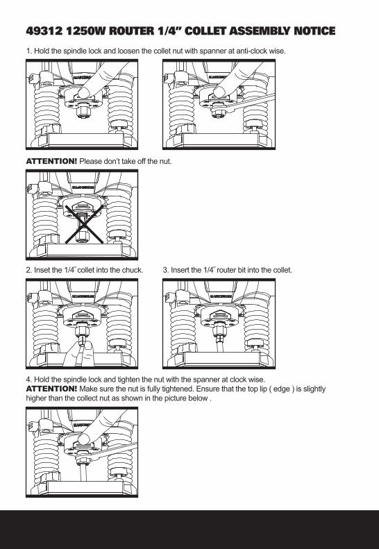
49312 1250W ROUTER 1/4” COLLET ASSEMBLY NOTICE
1. Hold the spindle lock and loosen the collet nut with spanner at anti-clock wise.
ATTENTION! Please don’t take off the nut.
2. Inset the 1/4˝ collet into the chuck. 3. Insert the 1/4˝ router bit into the collet.
4. Hold the spindle lock and tighten the nut with the spanner at clock wise.ATTENTION! Make sure the nut is fully tightened. Ensure that the top lip ( edge ) is slightly higher than the collect nut as shown in the picture below .

ROUTER 1250W TTB591ROU
GENERAL POWER TOOL SAFETY WARNINGS
WARNING: Read all safety warnings and all instructions. Failure to follow the warnings and instructions may result in electric shock, fire and/or serious injury.
Save all warnings and instructions for future reference.The term “power tool” in the warnings refers to your mains-operated (corded) power tool or battery-operated (cordless) power tool.
1) Work area safetya) Keep work area clean and well lit. Cluttered or dark areas invite accidents.b) Do not operate power tools in explosive atmospheres, such as in the presence of flammable liquids, gases or dust. Power tools create sparks which may ignite the dust or fumes.c) Keep children and bystanders away while operating a power tool. Distractions can cause you to lose control.
2) Electrical safetya) Power tool plugs must match the outlet. Never modify the plug in any way. Do not use any adapter plugs with earthed (grounded) power tools. Unmodified plugs and matching outlets will reduce risk of electric shock.b) Avoid body contact with earthed or grounded surfaces, such as pipes, radiators, ranges and refrigerators. There is an increased risk of electric shock if your body is earthed or grounded.c) Do not expose power tools to rain or wet conditions. Water entering a power tool will increase the risk of electric shock.d) Do not abuse the cord. Never use the cord for carrying, pulling or unplugging the power tool. Keep cord away from heat, oil, sharp edges or moving parts. Damaged or entangled cords increase the risk of electric shock.e) When operating a power tool outdoors, use an extension cord suitable for outdoor use. Use of a cord suitable for outdoor use reduces the risk of electric shock. f) If operating a power tool in a damp location is unavoidable, use a residual current device (RCD) protected supply. Use of an RCD reduces the risk of electric shock.
3) Personal safetya) Stay alert, watch what you are doing and use common sense when operating a power tool. Do not use a power tool while you are tired or under the influence of drugs, alcohol or medication. A moment of inattention while operating power tools may result in serious personal injury. b) Use personal protective equipment. Always wear eye protection. Protective equipment such as dust mask, non-skid safety shoes, hard hat, or hearing protection used for appropriate conditions will reduce personal injuries. c) Prevent unintentional starting. Ensure the switch is in the off-position before connecting to power source and/or battery pack,

picking up or carrying the tool. Carrying power tools with your finger on the switch or energising power tools that have the switch on invites accidents. d) Remove any adjusting key or wrench before turning the power tool on. A wrench or a key left attached to a rotating part of the power tool may result in personal injury. e) Do not overreach. Keep proper footing and balance at all times. This enables better control of the power tool in unexpected situations. f) Dress properly. Do not wear loose clothing or jewellery. Keep your hair, clothing and gloves away from moving parts. Loose clothes, jewellery or long hair can be caught in moving parts.g) If devices are provided for the connection of dust extraction and collection facilities, ensure these are connected and properly used. Use of dust collection can reduce dust-related hazards.
4) Power tool use and care a) Do not force the power tool. Use the correct power tool for your application. The correct power tool will do the job better and safer at the rate for which it was designed. b) Do not use the power tool if the switch does not turn it on and off. Any power tool that cannot be controlled with the switch is dangerous and must be repaired.c) Disconnect the plug from the power source and/or the battery pack from the power tool before making any adjustments, changing accessories, or storing power tools. Such preventive safety measures reduce the risk of starting the power tool accidentally. d) Store idle power tools out of the reach of children and do not allow persons unfamiliar with the power tool or these instructions to operate the power tool. Power tools are dangerous in the hands of untrained users. e) Maintain power tools. Check for misalignment or binding of moving parts, breakage of parts and any other condition that may affect the power tool’s operation. If damaged, have the power tool repaired before use. Many accidents are caused by poorly maintained power tools. f) Keep cutting tools sharp and clean. Properly maintained cutting tools with sharp cutting edges are less likely to bind and are easier to control. g) Use the power tool, accessories and tool bits etc. in accordance with these instructions, taking into account the working conditions and the work to be performed. Use of the power tool for operations different from those intended could result in a hazardous situation.
5) Servicea) Have your power tool serviced by a qualified repair person using only identical replacement parts. This will ensure that the safety of the power tool is maintained.
ROUTER 1250W TTB591ROU
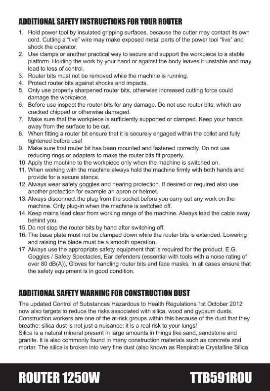
ADDITIONAL SAFETY INSTRUCTIONS FOR YOUR ROUTER1. Hold power tool by insulated gripping surfaces, because the cutter may contact its own
cord. Cutting a “live” wire may make exposed metal parts of the power tool “live” and shock the operator.
2. Use clamps or another practical way to secure and support the workpiece to a stable platform. Holding the work by your hand or against the body leaves it unstable and may lead to loss of control.
3. Router bits must not be removed while the machine is running.4. Protect router bits against shocks and impacts.5. Only use properly sharpened router bits, otherwise increased cutting force could
damage the workpiece. 6. Before use inspect the router bits for any damage. Do not use router bits, which are
cracked chipped or otherwise damaged.7. Make sure that the workpiece is sufficiently supported or clamped. Keep your hands
away from the surface to be cut.8. When fitting a router bit ensure that it is securely engaged within the collet and fully
tightened before use!9. Make sure that router bit has been mounted and fastened correctly. Do not use
reducing rings or adapters to make the router bits fit properly.10. Apply the machine to the workpiece only when the machine is switched on.11. When working with the machine always hold the machine firmly with both hands and
provide for a secure stance.12. Always wear safety goggles and hearing protection. If desired or required also use
another protection for example an apron or helmet.13. Always disconnect the plug from the socket before you carry out any work on the
machine. Only plug-in when the machine is switched off.14. Keep mains lead clear from working range of the machine. Always lead the cable away
behind you.15. Do not stop the router bits by hand after switching off.16. The base plate must not be clamped down while the router bits is extended. Lowering
and raising the blade must be a smooth operation.17. Always use the appropriate safety equipment that is required for the product. E.G.
Goggles / Safety Spectacles, Ear defenders (essential with tools with a noise rating of over 80 dB(A)), Gloves for handling router bits and face masks. In all cases ensure that the safety equipment is in good condition.
ADDITIONAL SAFETY WARNING FOR CONSTRUCTION DUST The updated Control of Substances Hazardous to Health Regulations 1st October 2012 now also targets to reduce the risks associated with silica, wood and gypsum dusts.Construction workers are one of the at-risk groups within this because of the dust that they breathe: silica dust is not just a nuisance; it is a real risk to your lungs!Silica is a natural mineral present in large amounts in things like sand, sandstone and granite. It is also commonly found in many construction materials such as concrete and mortar. The silica is broken into very fine dust (also known as Respirable Crystalline Silica

or RCS) during many common tasks such as cutting, drilling and grinding.Breathing in very fine particles of crystalline silica can lead to the development of:Lung cancerSilicosisChronic Obstructive Pulmonary Disorder (Chronic obstructive pulmonary disease (COPD)) And breathing in fine particles of wood dust can lead to the development of Asthma The risk of lung disease is linked to people who regularly breathe construction dust over a period of time, not on the odd occasion.To protect the lung, the COSHH Regulations sets a limit on the amount of these dusts that you can breathe (called a Workplace Exposure Limit or WEL) when averaged over a normal working day. These limits are not a large amount of dust: when compared to a penny it is tiny – like a small pinch of salt:This limit is the legal maximum; the most you can breathe after the right controls have been used.
How to reduce the amount of dust? 1. Reduce the amount of cutting by using the best sizes of building products.2. Use a less powerful tool e.g. a block cutter instead of angle grinder.3. Using a different method of work altogether – e.g. using a nail gun to direct fasten cable trays instead of drilling holes first.Please always work with approved safety equipment, such as those dust masks that specially designed to filter out microscopic particles and use the dust extraction facility at all time. For more information please see the HSE website:http://www.hse.gov.uk/construction or http://www.hse.gov.uk/pubns/cis69.pdf
WARNING! Some dust particles created by power sanding, sawing, grinding, drilling and other construction jobs contain chemicals known
to cause cancer, birth defects or other reproductive harm. Some examples of these chemicals are:• Lead from lead-based paints.• Crystalline silica from bricks and cement and other masonry products.• Arsenic and chromium from chemically treated timber.Your risk form these exposures varies, depending upon how often you do this type of work. To reduce your exposure to these chemicals:• Work in a well ventilated area.• Work with approved safety equipment, such as those dust masks that specially
designed to filter out microscopic particles and use the dust extraction facility at all time.
ROUTER 1250W TTB591ROU
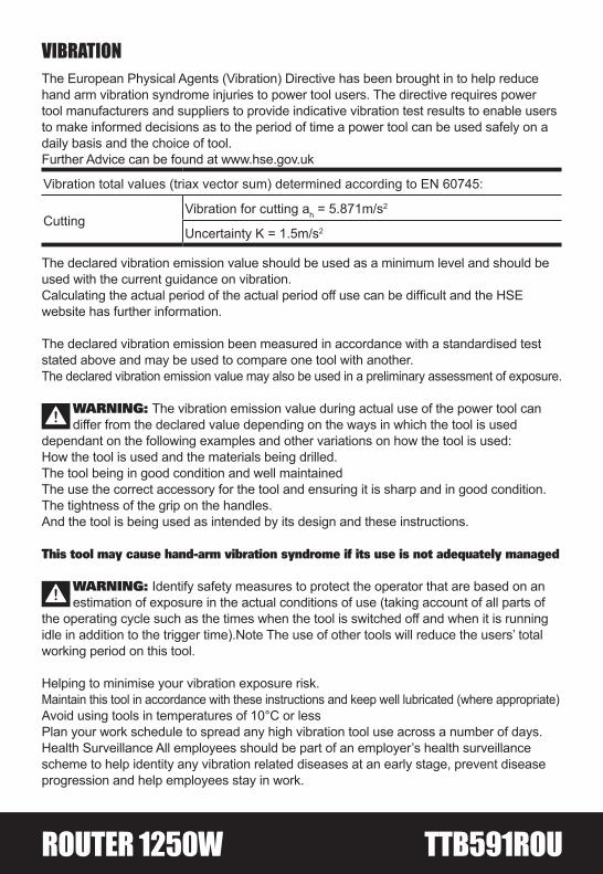
VIBRATIONThe European Physical Agents (Vibration) Directive has been brought in to help reducehand arm vibration syndrome injuries to power tool users. The directive requires powertool manufacturers and suppliers to provide indicative vibration test results to enable usersto make informed decisions as to the period of time a power tool can be used safely on adaily basis and the choice of tool.Further Advice can be found at www.hse.gov.uk
Vibration total values (triax vector sum) determined according to EN 60745:
CuttingVibration for cutting ah = 5.871m/s2
Uncertainty K = 1.5m/s2
The declared vibration emission value should be used as a minimum level and should be used with the current guidance on vibration.Calculating the actual period of the actual period off use can be difficult and the HSE website has further information.
The declared vibration emission been measured in accordance with a standardised test stated above and may be used to compare one tool with another.The declared vibration emission value may also be used in a preliminary assessment of exposure.
WARNING: The vibration emission value during actual use of the power tool can differ from the declared value depending on the ways in which the tool is used
dependant on the following examples and other variations on how the tool is used:How the tool is used and the materials being drilled.The tool being in good condition and well maintainedThe use the correct accessory for the tool and ensuring it is sharp and in good condition.The tightness of the grip on the handles.And the tool is being used as intended by its design and these instructions.
This tool may cause hand-arm vibration syndrome if its use is not adequately managed
WARNING: Identify safety measures to protect the operator that are based on anestimation of exposure in the actual conditions of use (taking account of all parts of
the operating cycle such as the times when the tool is switched off and when it is running idle in addition to the trigger time).Note The use of other tools will reduce the users’ total working period on this tool.
Helping to minimise your vibration exposure risk.Maintain this tool in accordance with these instructions and keep well lubricated (where appropriate)Avoid using tools in temperatures of 10°C or lessPlan your work schedule to spread any high vibration tool use across a number of days.Health Surveillance All employees should be part of an employer’s health surveillance scheme to help identity any vibration related diseases at an early stage, prevent disease progression and help employees stay in work.
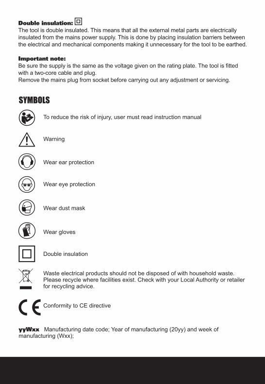
Double insulation: The tool is double insulated. This means that all the external metal parts are electrically insulated from the mains power supply. This is done by placing insulation barriers between the electrical and mechanical components making it unnecessary for the tool to be earthed.
Important note:Be sure the supply is the same as the voltage given on the rating plate. The tool is fitted with a two-core cable and plug.Remove the mains plug from socket before carrying out any adjustment or servicing.
SYMBOLS
To reduce the risk of injury, user must read instruction manual
Warning
Wear ear protection
Wear eye protection
Wear dust mask
Wear gloves
Double insulation
Waste electrical products should not be disposed of with household waste.Please recycle where facilities exist. Check with your Local Authority or retailerfor recycling advice.
Conformity to CE directive
yyWxx Manufacturing date code; Year of manufacturing (20yy) and week of manufacturing (Wxx);
ROUTER 1250W TTB591ROU
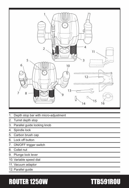
1. Depth stop bar with micro-adjustment2. Turret depth stop3. Parallel guide locking knob4. Spindle lock5. Carbon brush cap6. Lock off button7. ON/OFF trigger switch8. Collet nut9. Plunge lock lever10. Variable speed dial11. Vacuum adaptor12. Parallel guide
1
65
12
10
138 97
1415
16
411
3
2
13. Spanner14. Centring pin15. Collet16. Guide bush
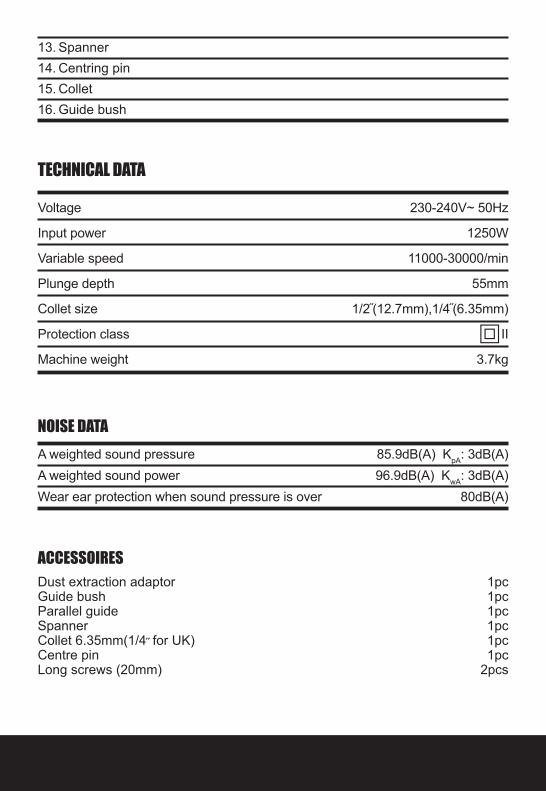
TECHNICAL DATA
Voltage 230-240V~ 50Hz
Input power 1250W
Variable speed 11000-30000/min
Plunge depth 55mm
Collet size 1/2˝(12.7mm),1/4˝(6.35mm)
Protection class II
Machine weight 3.7kg
NOISE DATAA weighted sound pressure 85.9dB(A) KpA: 3dB(A)A weighted sound power 96.9dB(A) KwA: 3dB(A)Wear ear protection when sound pressure is over 80dB(A)
ACCESSOIRESDust extraction adaptor 1pcGuide bush 1pcParallel guide 1pcSpanner 1pcCollet 6.35mm(1/4˝ for UK) 1pcCentre pin 1pcLong screws (20mm) 2pcs
ROUTER 1250W TTB591ROU
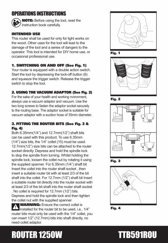
OPERATIONS INSTRUCTIONSNOTE: Before using the tool, read the instruction book carefully.
INTENDED USEThis router shall be used for only for light works on the wood. Other uses for the tool will lead to the damage of the tool and a series of dangers to the operator. This tool is intended for DIY home use, or occasional professional use.
1. SWITCHING ON AND OFF (See Fig. 1)Your router is equipped with a double action switch. Start the tool by depressing the lock-off button (6) and squeeze the trigger switch. Release the trigger switch to stop the tool.
2. USING THE VACUUM ADAPTOR (See Fig. 2)For the sake of your health and working nvironment,always use a vacuum adaptor and vacuum. Use the two long screws to fasten the adaptor socket securely to the routing base. The adaptor socket is suitable for vacuum adaptor with a suction hose of 35mm diameter.
3. FITTING THE ROUTER BITS (See Fig. 3 & Fig. 4)Both 6.35mm(1/4˝) and 12.7mm(1/2˝) shaft bits can be used with this product. To use 6.35mm (1/4˝) size bits, the 1/4˝ collet (15) must be used. 12.7mm(1/2˝) size bits can be attached to the router socket directly. Depress and hold the spindle lock to stop the spindle from turning. Whilst holding the spindle lock, loosen the collet nut by rotating it using the supplied spanner. For 6.35mm (1/4˝) shaft bit Insert the collet into the router shaft socket , then insert a suitable router bit with at least 2/3 of the bit shaft into the collet. For 12.7mm (1/2˝) shaft bit Insert a suitable router bit directly into the router socket with at least 2/3 of the bit shaft into the router shaft socket . No collet is required for 12.7mm (1/2˝) bits.Depress and hold the spindle lock and then tighten the collet nut with the supplied spanner.
WARNING: Ensure the correct collet is installed for the router bit to be used, i.e., 1/4”
router bits must only be used with the 1/4” collet, you can insert 1/2” (12.7mm) bits into shaft directly, no need collet adaptor.
Fig. 3
Fig. 4
Fig. 1
Fig. 2
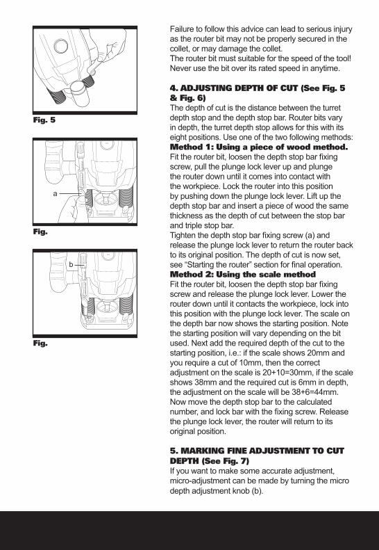
Failure to follow this advice can lead to serious injury as the router bit may not be properly secured in the collet, or may damage the collet.The router bit must suitable for the speed of the tool! Never use the bit over its rated speed in anytime.
4. ADJUSTING DEPTH OF CUT (See Fig. 5 & Fig. 6)The depth of cut is the distance between the turret depth stop and the depth stop bar. Router bits vary in depth, the turret depth stop allows for this with its eight positions. Use one of the two following methods:Method 1: Using a piece of wood method.Fit the router bit, loosen the depth stop bar fixing screw, pull the plunge lock lever up and plunge the router down until it comes into contact with the workpiece. Lock the router into this position by pushing down the plunge lock lever. Lift up the depth stop bar and insert a piece of wood the same thickness as the depth of cut between the stop bar and triple stop bar.Tighten the depth stop bar fixing screw (a) and release the plunge lock lever to return the router back to its original position. The depth of cut is now set, see “Starting the router” section for final operation.Method 2: Using the scale method Fit the router bit, loosen the depth stop bar fixing screw and release the plunge lock lever. Lower the router down until it contacts the workpiece, lock into this position with the plunge lock lever. The scale on the depth bar now shows the starting position. Note the starting position will vary depending on the bit used. Next add the required depth of the cut to the starting position, i.e.: if the scale shows 20mm and you require a cut of 10mm, then the correctadjustment on the scale is 20+10=30mm, if the scale shows 38mm and the required cut is 6mm in depth, the adjustment on the scale will be 38+6=44mm.Now move the depth stop bar to the calculated number, and lock bar with the fixing screw. Release the plunge lock lever, the router will return to its original position.
5. MARKING FINE ADJUSTMENT TO CUTDEPTH (See Fig. 7)If you want to make some accurate adjustment,micro-adjustment can be made by turning the micro depth adjustment knob (b).
Fig. 5
Fig. 8
Fig. �
Fig. �
a
b
ROUTER 1250W TTB591ROU
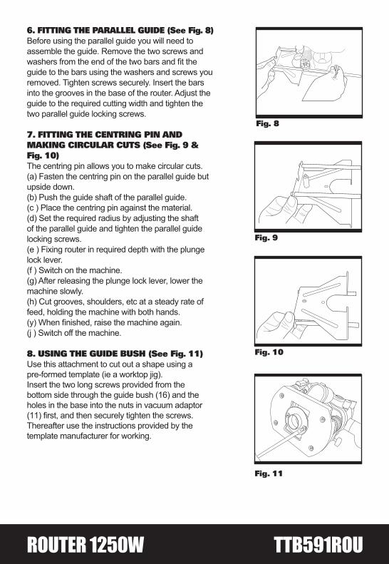
6. FITTING THE PARALLEL GUIDE (See Fig. 8)Before using the parallel guide you will need to assemble the guide. Remove the two screws and
guide to the bars using the washers and screws you removed. Tighten screws securely. Insert the bars into the grooves in the base of the router. Adjust the guide to the required cutting width and tighten the two parallel guide locking screws.
7. FITTING THE CENTRING PIN ANDMAKING CIRCULAR CUTS (See Fig. 9 & Fig. 10)The centring pin allows you to make circular cuts.(a) Fasten the centring pin on the parallel guide but upside down.(b) Push the guide shaft of the parallel guide.(c ) Place the centring pin against the material.(d) Set the required radius by adjusting the shaft of the parallel guide and tighten the parallel guide locking screws.(e ) Fixing router in required depth with the plunge lock lever.(f ) Switch on the machine.(g) After releasing the plunge lock lever, lower the machine slowly.(h) Cut grooves, shoulders, etc at a steady rate of feed, holding the machine with both hands.
(j ) Switch off the machine.
8. USING THE GUIDE BUSH (See Fig. 11)Use this attachment to cut out a shape using a pre-formed template (ie a worktop jig). Insert the two long screws provided from the bottom side through the guide bush (16) and the holes in the base into the nuts in vacuum adaptor (11) first, and then securely tighten the screws.Thereafter use the instructions provided by the template manufacturer for working.
Fig. 9
Fig. 10
Fig. 8
Fig.
Fig. 11
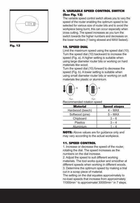
Fig. 12
9. VARIABLE SPEED CONTROL SWITCH (See Fig. 12)The variable speed control switch allows you to vary the speed of the router enabling the optimum speed to be selected for various size of router bits and to avoid the workpiece being burnt, this can occur especially when cross cutting. The speed increases as you turn the switch towards the higher numbers and decreases on the lower numbers (1 being slowest and MAX fastest).
10. SPEED DIALLimit the maximum speed using the speed dial (10).Turn the speed dial (10) backward to increase the speed (Fig. a). A higher setting is suitable when using large diameter router bits or working on hard materials like wood.Turn the speed dial (10) forward to decrease the speed (Fig. b). A lower setting is suitable when using small diameter router bits or working on soft materials like plastic or aluminium.
Recommended rotation speedMaterial Speed stages
Hardwood (beech) 4 – MAXSoftwood (pine) 5 – MAX
Chipboard 3 – 6Plastics 3 – 4
Aluminium 1 – 4
NOTE: Above values are for guidance only and may vary according to the actual workpiece.
11. SPEED CONTROL1. Increase or decrease the speed of the router, rotating the dial. The speed increases as the numbers on the dial increase.2. Adjust the speed to suit different working materials. The tool works quicker and smoother at different speeds when working in different woods.3. Determine the optimum speed by making a trial cut in a scrap piece of material.The setting on the dial equates approximately to no-load speeds that increase from approximately 11000min-1 to approximatel 30000min-1 in 7 steps.
ROUTER 1250W TTB591ROU
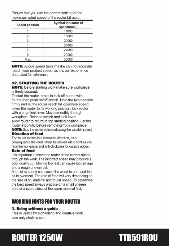
Ensure that you use the correct setting for the maximum rated speed of the router bit used.
Speed position Symbol indicator of speed(min-1)
1 110002 150003 200004 240005 270006 29000
Max 30000
NOTE: Above speed table maybe can not accurate match your product speed, as it is our experience data. Just for reference.
12. STARTING THE ROUTERNOTE: Before starting work make sure workpiece is firmly secured.To start the router, press in lock off button with thumb then push on/off switch. Hold the two handles firmly and let the router reach full operation speed, lower the router to its working position, lock router with plunge lock leve. Move smoothly through workpiece. Release switch and lock lever,allow router to return to top starting position. Let the router stop fully before removing from workpiece. NOTE: Stop the router before adjusting the variable speed.Direction of feedThe router rotates in a clockwise direction, as a consequence the router must be moved left to right as you face the workpiece and anti-clockwise for outside edges.Rate of feedIt is important to move the router at the correct speed through the work. The incorrect speed may produce a poor quality cut. Moving too fast can cause bit damage and a rough uneven cut.A too slow speed can cause the wood to burn and the bit to overheat. The rate of feed will vary depending on the size of bit, material and router speed. To determine the best speed always practice on a small unseen area or a spare piece of the same material first.
WORKING HINTS FOR YOUR ROUTER1. Using without a guideThis is useful for signwriting and creative work.Use only shallow cuts.

2. Rate of feedThe cutter of your router rotates clockwise.For more efficient cutting, move your router from left to right as you stand facing the workpiece.NOTE: When cutting outside edges, move your router anticlockwise and clockwise when cutting inside edges.
MAINTENANCERemove battery from the tool and the plug from the socket before carrying out any adjustment, servicing or maintenance.Your power tool requires no additional lubrication or maintenance. There are no user serviceable parts in your power tool. Never use water or chemical cleaners to clean your power tool. Wipe clean with a dry cloth. Always store your power tool in a dry place. Keep the motor ventilation slots clean. Keep all working controls free of dust. Occasionally you may see sparks through the ventilation slots. This is normal.If the supply cord of the charger is damaged, it must be replaced by the manufacturer, its service agent or similarly qualified persons in order to avoid a hazard.
REPLACING THE CARBON BRUSH (See Fig. 13)If you suspect that the brush may be worn or as a purely precautionary measure, it can be removed and inspected and replaced if required. Firstly remove the cap over the brush housing with a screwdriver. You can now remove the old carbon brush. Slide the new brush into the housing and relocate the cap and secure. Once the brush has been replaced check and confirm that the router still operates.Allow the unit to run for a few minutes to enable the new brushes to ‘bed’ down.
ENVIRONMENTAL PROTECTIONWaste electrical products should not be disposed of with household waste. Please recycle where facilities exist. Check with your
Local Authority or retailer for recycling advice. For further information visit www.recyclemore.co.uk
Fig. 13
ROUTER 1250W TTB591ROU
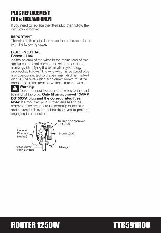
PLUG REPLACEMENT (UK & IRELAND ONLY)If you need to replace the fitted plug then follow theinstructions below.
IMPORTANTThe wires in the mains lead are coloured in accordancewith the following code:
BLUE =NEUTRALBrown = LiveAs the colours of the wires in the mains lead of thisappliance may not correspond with the colouredmarkings identifying the terminals in your plug,proceed as follows. The wire which is coloured bluemust be connected to the terminal which is markedwith N. The wire which is coloured brown must beconnected to the terminal which is marked with L.
Warning:Never connect live or neutral wires to the earth
terminal of the plug. Only fit an approved 13AMPBS1363/A plug and the correct rated fuse.Note: If a moulded plug is fitted and has to beremoved take great care in disposing of the plugand severed cable, it must be destroyed to preventengaging into a socket.
13 Amp fuse approvedto BS1362
ConnectBlue to N(neutral)
Outer sleevefirmly clamped
Brown L(live)
Cable grip

Declaration of conformityWe, Importer
Titan Power Tools (UK) LtdTrade House, Mead Avenue, BA22 8RT
Declare that the product:Designation: ROUTER 1250W
Model: TTB591ROU
Complies with the following Directives:2014/30/EU Electromagnetic Compatibility Directive,
2006/42/EC Machinery Directive2014/35/EU Low Voltage Directive,
2011/65/EU Restrictions of the Use of Certain Hazardous Substances in Electrical and Electronic Equipment
2012/19/EU Waste Electrical and Electronic Equipment (WEEE)
Standards and technical specifications referred to:EN 60745-1: 2009 + A11: 2010
EN 60745-2-17: 2010EN55014-1:2006+A1:2009+A2:2011EN 55014-2:1997+A1:2001+A2:2008
EN 61000-3-2: 2014EN 61000-3-3: 2013
Authorised signatory and technical file holder
Date: 02/11/16
Signature:
Name / title: John Fretwell / Quality Assurance Manager
Titan Power Tools (UK) Ltd. Trade House, Mead Avenue, BA22 8RT