Embed Size (px)
Citation preview

ORIGINAL ARTICLE
Review of improvements in wire electrode properties for longerworking time and utilization in wire EDM machining
Ibrahem Maher & Ahmed A. D. Sarhan & M. Hamdi
Received: 25 March 2014 /Accepted: 5 August 2014 /Published online: 30 August 2014# Springer-Verlag London 2014
Abstract Wire electrical discharge machining (WEDM) is animportant technology, which demands high-speed cutting andhigh-precision machining to realize productivity and im-proved accuracy for manufacturing hard materials. WEDMhas experienced explosive growth and complexity of equip-ment as well as rising demand for the basic process tool (thewire electrode). Greater taper angles, thicker workpieces, au-tomatic wire threading, and long periods of unattended oper-ation make the selection of the ideal wire a much more criticalbasis for achieving successful operation. This paper focuseson the evolution of EDM wire electrode technologies fromusing copper to the widely employed brass wire electrodesand from brass wire electrodes to the latest coated wire elec-trodes. Wire electrodes have been developed to help userdemand and needs through maximum productivity and quan-tity by choosing the best wire. In the final part of the paper, thepossible trends for future WEDM electrode research arediscussed.
Keywords WEDM .Coatedwires .Brasswires .Steelwires .
Diffusion annealed . Composite wire electrodes
1 Introduction
Wire electrical discharge machining (WEDM) is among themore widely known and applied non-traditional machiningprocesses in industry today. In this procedure, improvementsto the process mechanism and control have rapidly beentaking place. WEDM can machine harder, they are higherstrength, corrosive and wear-resistant, and difficult-to-machine materials. With WEDM, it is also possible to ma-chine complicated shapes that cannot otherwise be achievedusing traditional machining processes, such as turning, mill-ing, and grinding. Applications of WEDM include extrusiondies, fuel injector nozzles, aircraft engine turbine blades, andmachining of difficult-to-machine materials like tool steel,titanium, metal matrix composites (MMCs), and cementedcarbides [1–5]. Besides machining electrically conductiveworkpieces, some WEDM work has also been reported oninsulating ceramics and non-conductive materials [6–9].
The Russian Lazarenko couple designed the firstelectrodischarge machine in 1955 [10]. Ten years later, anumerically controllable wire discharge machine was devel-oped, and in 1969, a machine for mass production was built.Most wire discharge machine controllers have been enhancedwith computer numerical control equipment. As for wireelectrodes, pure copper wires were used in the early 1970sbut at the cost of accuracy and strength. In the second half ofthe 1970s, brass wire started to be used instead of pure copperwire. In 1980, copper wire electrodes coated with zinc and, inthe following year, brass wire electrodes coatedwith zinc weredeveloped and utilized. Brass wire electrodes with addedaluminum or chromium were made as well. From 1990 on-wards, brass wire electrodes coated with zinc for high-precision cutting and coated Cu-50mass%Zn for high-speedcutting were developed. Subsequently, core materials of stain-less wire coated with copper were made and utilized. Also,new types of wire were developed which offered higher
I. Maher :A. A. D. Sarhan (*) :M. HamdiCentre of Advanced Manufacturing and Material Processing,Department of Mechanical Engineering, Faculty of Engineering,University of Malaya, 50603 Kuala Lumpur, Malaysiae-mail: [email protected]
I. MaherDepartment of Mechanical Engineering, Faculty of Engineering,Kafrelsheikh University, Kafrelsheikh 33516, Egypt
A. A. D. SarhanDepartment of Mechanical Engineering, Faculty of Engineering,Assiut University, Assiut 71516, Egypt
Int J Adv Manuf Technol (2015) 76:329–351DOI 10.1007/s00170-014-6243-3

cutting speed due to increased zinc concentration and wireelectrodes made of brass with added titanium and aluminumfor improved heat resistance when cutting thick materials [11,12]. Moreover, other special wire electrodes were developedtomeet specific cutting conditions and materials, such as steel,tungsten, molybdenum, and abrasive-assisted and porous wireelectrodes [13].
As for WEDM, demand is on the rise for high-speedcutting and high-precision machining for the purpose of im-proving the productivity of molds as well as for achievinghigh-quality machined workpieces. Wires used in WEDM arethe core of the system. Brass wire electrodes are extensivelyused as WEDM tools. However, along with recent variationsin manufacturing field applications, there is an expandingdemand for wire electrodes with superior performance to theconventional brass wire electrodes. High-performance wires,including coated, composite, and diffusion-annealed wires arecharacterized by high conductivity and good sparking ability.These electrodes are generally zinc-coated wires with acopper-brass alloy or steel core, the brass containing either asmall amount of chromium or high concentration of zinc. Atpresent, WEDM users are interested in shortening the machin-ing time of products [14–17]. A new, high-performance EDMwire would be expected to provide both high cutting speedand improved accuracy. Thus, this paper focuses on studyingimprovements of physical, mechanical, and electrical proper-ties of wire electrodes for high-performance WEDMprocesses.
2 Wire EDM process
In WEDM, mater ia l removal is based upon theelectrodischarge erosion effect of electric sparks occurringbetween the wire electrode and workpiece. The two are sep-arated by a dielectric fluid, as shown in Fig. 1. A pulse voltage
is applied between the wire electrode and workpiece in theprocessing fluid to melt the workpiece surface with the ther-mal energy of a spark discharge, while simultaneously remov-ing machining dust through a vaporizing explosion and recir-culation of the processing fluid. Continuous machining thusbecomes possible while running the wire electrode. The resi-due ensuing from the melting and vaporization of a smallvolume of the surfaces of both workpiece and EDM wireelectrode is contained in a gaseous envelope (plasma). Theplasma eventually collapses during off-time. The liquid andvapor phases created by the melting and vaporization of thematerial are quenched by the dielectric fluid to form soliddebris. This process is repeated at nanosecond intervals (de-pending on the cycle time) along the length of the wire in thecutting zone [18–20].
To achieve a successful operation, selecting the correctwire electrode for WEDM is a very challenging task [21].As a result, experimentation with different wire electrodes isessential if optimum results are to be achieved. The wireelectrodes used in WEDM must have two important charac-teristics: high electrical conductivity and sufficient mechanicalstrength. WEDM performance is attributed to mainly sixfactors, as shown in Fig. 2 [22–24].
3 Wire electrode properties
In general, the cutting performance of the WEDM proceduredepends on a combination of electrical, mechanical, physical,and geometrical properties of the wire electrode. The factorsnot related to the wire but which are involved in WEDM,including the mechanical machine concept, improved ma-chine intelligence, use of new pulse generators, and dielectricflushing techniques, also affect machining performance. Thefollowing section describes the key physical properties ofEDMwires and how they relate to real-world cutting [25–27].
Conductivity is an important property of the EDM wiresince it determines how the power supply energy istransferred over the distance from the power feed sourceto the actual point of cutting. This distance can be con-siderable, especially if the job is to cut with open guidesto clear a workpiece obstruction. Low wire conductivitywill result in a voltage drop and associated energy lossover the distance from the power feed to the cutting point.This is not insignificant considering that the peak currentof most modern power supplies often exceeds 100 amps.Conductivity is often expressed as a percentage of IACS(International Annealed Copper Standard), which is aunit of electrical conductivity for metals and alloys rela-tive to standard annealed copper [28].Tensile strength indicates the wire’s ability to withstandthe tension imposed upon it during cutting in order toFig. 1 Wire electric discharge machining (WEDM) schematic diagram
330 Int J Adv Manuf Technol (2015) 76:329–351

make a vertically straight cut [29]. EDM wires are con-sidered “hard” at tensile strengths of 900 MPa or above,“half hard” at tensile strengths around 490 MPa, and“soft” at tensile strengths below 440 MPa. Hard wiresare commonly used for most work, while half hard andsoft wires are primarily used for taper cuts where the taperangle is greater than 5°, since a hard wire will resistbending at the guide pivot and cause inaccurate tapercutting. Half hard and soft wires are often unsuitable forautomatic threading unless the machine is specificallydesigned to work with such wires [30].Elongation is an important property since EDM wiresoperate in hostile environments under high tension andget attacked by thousands of sparks at their cross section.Elongation describes to what extent the wire gives orplastically deforms just before it breaks. Elongation ismeasured in the percent of gauge length used in a giventest. It could also be stated that elongation relates to howbrittle the wire is. Usually, hard wires have considerablyless elongation than half hard wires. A brittle wire mightbreak at the first overload condition, while a more ductilewire is expected to accept a temporary overload.Melting point is not normally specified for a given wirebut is obviously important since WEDM is a spark ero-sion process. Also, the wire electrode should be some-what resistant to the rapid melting by the sparks.Straightness is another important property of EDM wiresthat is seldom specified but is critically important tosuccessful autothreading and cutting thicker workpieces.Cleanliness is a property that is not specified for EDMwires. Wires may get dirty due to contamination byresidual metal powder left over from the drawing process,drawing lubricant, or paraffin added to the wire by somemanufacturers prior to spooling. Dirty wires result inclogged guides and power feeds or slipping belts orrollers.Geometrical properties are the wire’s diameter, shape,and coating and layer structure.Wires ranging in diameter
from 0.02 to 0.36mm are generally available forWEDM.An increase in diameter results in an increase of pulseenergy supplied to the working gap, thus increasing theoverall material removal rate [31, 32]. On the other hand,for micro-WEDM where small pulse energies are pre-dominant, using ultra-fine wires less than 30 microns indiameter is required [33]. A number of other wire elec-trode shapes have also been conceived in many patents[34–36]. Meanwhile, the use of modified cylindricalwires is rather limited due to their high manufacturingcost. A cutting rate increase of up to 15–20 % has beenobserved owing to the enhanced heat transfer in six-lobedwire electrodes [37]. Wire electrodes with twisted groveshave been patented in order to avoid the occurrence ofsparks at the same point [38]. Regarding their patents,several inventors have disclosed that sparks generated inWEDM moved close to the parts and hot spots on thewire electrode are prevented owing to the change indirection of the wire’s rectangular cross section [39, 40].Figure 3 depicts some of the different wire shapes pat-ented to enhance material removal rate [37, 38, 40,41]. In 1969, a 0.15-mm diameter wire was appliedto achieve the maximum possible cutting rate; thediameter was subsequently enhanced to 0.36 mm.Figure 4 illustrates the increase in wire diameterwith the developed wire electrode for WEDM pro-cess improvement [42, 11]. Efforts have been madein the past to identify and analyze the importantforce components acting on the smaller-diameterwire electrode (0.03 mm), like electrostatic, electro-magnetic, dielectric flushing, wire traction, wirefeed, etc. [43, 44].
Like most other things in life, finding the opti-mum wire for any application means reaching anacceptable compromise among the above-mentionedproperties, since they are frequently conflicting. Forexample, high conductivity wires often have lowtensile strength.
WEDM Performance Measures
Cutting Rate – Surface Roughness
Dimensional Deviation
White Layer Thickness
Gap Current – Wire Rupture
Fig. 2 Effect of various factorsimproving the WEDMperformance [22]
Int J Adv Manuf Technol (2015) 76:329–351 331

4 Development of EDM wire electrodes
The first machines in the early 70s were extremely slow, withcutting rates of about 21 mm2/min. Cutting rates went up inthe early 80s to 64 mm2/min, while today, machines areequipped with automatic wire threading and can cut over 20times faster than the earliest machines [45, 20].
For high-speed cutting and high-precision machining, anywire electrode should have key physical properties, viz highelectrical conductivity, tensile strength, elongation, meltingpoint, and straightness [46–48].
Technologies with brass-coated wires are categorized asHIH (high hawk), HIF (high falcon), HIE (high eagle), HIR(high real), and HIS (high sonic) [27]. HIS and HIR wireelectrodes were developed for high-speed EDM applicabilityand are being utilized for mass production applications likemetal molds for IC lead frames and electronic parts. Figure 5
shows various wire electrodes built for better roughness andflatness with faster cutting speed [49].
Adding zinc to the wire electrode helps control electricaldischarge properties, subsequently enhancing machining per-formance. The addition of conductive alloying elements to thecore surface of wire electrodes controls clarification and heatrelease [50]. Several inventors [51–53] have focused theirefforts toward enhancing wire electrode performance by con-trolling the above methods. Significant increase in the perfor-mance of WEDM has been reported with single (plain wireelectrodes) or multi-component (zinc-coated, diffusionannealed, etc.) wire electrodes [54, 55]. Brass wire electrodesare extensively used on account of their ability to generatestable discharge, but their electrical conductivity is low. Manywire electrodes have been developed by considering the elec-trical conductivity and heat resistance of the coated layer orcore material. One property that noticeably affects WEDMperformance is fracture toughness. Fracture toughness is theability of the wire electrode to resist breakage and withstandthe formation of craters on its surface [56–58]. Wires withhigh tensile strength can be made, but as a result have atendency to break. Composite wire electrodes with a steelcore and high fracture toughness have been developed toaddress the wire fracture and electrical conductivity problems.An EDM wire will break when a discharge introduces a flawinto the wire that is greater than the critical flaw size needed totrigger catastrophic failure under the preload tension applied(Fig. 6) [59]. Many high-strength materials, including EDMwires, are notorious for their low fracture toughness, that is,their inability to withstand relatively small flaws withoutfailing. Each and every discharge in the WEDM processmakes a crater, which is termed a defect or flaw, in both thewire and workpiece. As flushing conditions deteriorate, thoseflaws tend to become larger and larger, eventually causingdisastrous wire failure [60–62]. Figure 7 shows the rapidadvancement rate of WEDM with standard wire and high-performance wire electrodes since its introduction [42, 63,64].
5 Plain EDM wires
Typically, brass wire begins as a continuously cast 20-mmdiameter rod. This rod is either cold rolled or cold drawn untilit is approximately a 6-mm round or hexagonal cross section.The wire is then annealed and drawn through a series of diesuntil it is around 0.9 mm in diameter. In this state, it iscommonly called a “redraw” wire. The redraw wire is subse-quently drawn through another series of diamond dies until itreaches the final size. At final size, the wire is resistivelyannealed or thermally tempered in an inert atmosphere,cleaned, and then spooled [65–67].
Fig. 3 Customized wire shapes [37, 38, 40, 41]
Fig. 4 Higher cutting rate machines using thick wires [11]
332 Int J Adv Manuf Technol (2015) 76:329–351

In the EDM wire trade, plain merely means the wireconsists of a single homogeneous component and does nothave a coated or composite construction [30].
5.1 Copper wire
Copper wire, shown in Fig. 8, was the original material used inWEDM. At the time, it was believed that because copper wirehad high electrical conductivity it would make the ideal EDMwire. Unfortunately, copper wire has low tensile strength, highmelting point, and low vapor pressure rating [68]. This soonbecame apparent with the development of the second-generation pulse-type power supplies, and copper wire wasshortly replaced by brass wire. It should be noted that copperwire is still used occasionally for applications in which zinc(contained in brass or coated wires) is considered an unac-ceptable contaminant [69, 30].
5.2 Brass wire
Various attempts have been made in the past to improve wireelectrodes. Brass EDM wire is a combination of copper andzinc, typically alloyed in the range of 63–65 % Cu and 35–37 % Zn (Fig. 9) [63]. It has been discovered that the additionof zinc improves cutting performance and speed com-pared to copper in several ways [46]. During the cuttingprocess, the zinc in the brass wire actually boils off orvaporizes, which helps cool the wire and deliver moreusable energy to the work zone. Adding zinc providessignificantly higher tensile strength and greater vaporpressure rating, which offsets the relative losses in con-ductivity. Also, some zinc particles that are not filteredout of the dielectric fluid would remain in the gapbetween the electrode and the workpiece to help thegap ionization and cutting process [42]. Brass rapidlybecame the most widely used electrode material forgeneral-purpose wire EDM.
It is worth noting that even a small amount of zincadded to copper wire severely reduces conductivity. Theconductivity of hard brass wire is typically only 20 %that of copper wire. Since it is zinc that gives the brasswire its improved flushability, some manufacturers nowoffer a high-zinc brass of Cu60%Zn40%. This increasein zinc content can increase cutting speed up to 5 % insome optimized applications [70]. However, it is notpractical to cold-draw wire with zinc content in excessof 40 %. Changes in the wire grain structure make thewire too brittle for further processing into the finediameters necessary for wire EDM. In some circum-stances, significant brass deposit can remain on theworkpiece after the cut, which is proven to be difficultto remove. These facts have led to the development ofcoated wires [71, 72, 14].
Electric discharge wire electrode line-upFig. 5 Characterization ofelectrical discharge wire electrode[49]
Fig. 6 Showing a defect and a fracture in the wire EDM process [62]
Int J Adv Manuf Technol (2015) 76:329–351 333

5.3 Aluminum-brass wire
Adding a small percentage of aluminum to a brass wire createsa specialty alloy wire, as shown in Fig. 10. Such alloy addi-tions improve the wire’s tensile properties, allowing for tensilestrength to be brought up to as high as 1,200 MPa withoutadversely affecting elongation. Some users claim these wiresare less prone to breakage than other types of plain brass wire[30].
6 Coated EDM wires
US Patent No. US1896613-1933 is one of the earliest patentson zinc-coated wires directed toward improving the quality ofsuch wires [73].
Due to the limitations in producing plain brass wire withalloy percentages greater than 40 % zinc, coated wires weredeveloped in an attempt to put zinc on the surface of the wirewhile retaining a core wire material that could be successfullydrawn [74]. Coated wires are produced by plating or hotdipping redrawn wire and subsequently drawing it to the finalsize. This is a difficult process since the plated surface zinc hasto endure the final drawing process and still present a uniform
coating to the cut. Currently, no EDMwires are manufacturedby a process in which the coating is deposited at the final wiresize. They typically have a core of brass or copper for con-ductivity and tensile strength and are electroplated with acoating of pure or diffused zinc for enhanced spark formationand flush characteristics [75–81].
6.1 Single-layer coated wires
Zinc-coated brass wire was one of the first attempts to presentmore zinc to the wire’s cutting surface. This wire consists of athin (around 5 microns) zinc coating over a core, which is oneof the standard EDM brass alloys (Fig. 11). Zinc-coated brasswire offers a significant increase in cutting speed over plainbrass wire, with no loss in any of the other critical properties[82]. Exceptional surface finish can be obtained when cuttingtungsten carbide, and this wire is often utilized for cuttingpolycrystalline diamond and graphite. This wire is also uti-lized in circumstances in which brass wire produces unaccept-able brass plating on the workpiece.
Zinc-coated copper wire was another early attempt to com-bine the conductivity of a copper core with the flushability ofzinc. It has no current application because when sparks pen-etrate the thin zinc coating, the cutting rate slows to thesluggish pace of pure copper wire [83, 84].
Fig. 7 Advancement of theWEDM rate since itsdevelopment
100%Cu
Fig. 8 Solid copper [30]
65Cu35Zn
Fig. 9 Solid brass [30]
334 Int J Adv Manuf Technol (2015) 76:329–351

US Patent No. US4287404 disclosed that coating a wireelectrode with a metal or alloy having a low vaporizationtemperature, such as zinc, cadmium, tin, lead, antimony, bis-muth, or alloys thereof, protects the core of the wire againstthermal shock resulting from the occurrence of electricaldischarge. Additionally, increasing the frequency of the elec-trical discharges without running the risk of rupturing the wireis feasible [85]. Patent No. US6300587 is for a wire electrodecontaining a core, and coating layer formed on the outerperiphery of the core contains copper. The coating layercomprises an alloy of 55.5 to 75 wt% copper and at leastone element selected from the group consisting of Zn, Cs, Se,Te, and Mg. The coating layer does not have an oxide filmthereon other than a natural oxide film [86]. Patent No.US6348667 refers to a wire electrode that prevents the corro-sion, particularly of the non-eroded surfaces of the hard metalblock. This purpose is attained by selecting a wire electrodefor the spark-erosive cutting of hard metals, the outer coat ofwhich consists of a metal or metal alloy and which is notnobler than the binder contained in the hardmetal. Thus, smallmetal particles of the outer coat come loose during cutting dueto wear of the outer wire electrode coat, and they remain in thedielectric. However, since these small metal particles are notnobler than the metal contained in the hard metal, electro-chemical corrosion, namely pitting of the hard metal, cantherefore not occur as soon as the small metal particles come
into contact with the hard metal block. Consequently, thepitting phenomena in the hard metal block are avoided. As arule, the hard metal block contains cobalt, aluminum, magne-sium, zinc, or iron [87].
6.2 Double-layer coated wires
US Patent No. US4968867 discloses a wire electrode with acore wire having relatively high thermal conductivity, a lowercoating layer formed by a low boiling point material and anoutermost brass layer with highmechanical strength. Here, thecore wire is made of copper, silver, aluminum, or alloys(Fig. 12). Certain effects, such as the vibration dumping effect,heat transfer effect, and resistance to breakage, were observed,all of which ultimately increase machining speed. Figure 12ashows a cross-sectional view of the first embodiment of thewire electrode invented. A core wire (6) is covered by acoating layer (7). In this embodiment, brass containing 35 %Zn is used for the core wire coating layer, and a Cu-Sn alloyincluding 0.15 % Sn balanced by Cu is used for the core wire.Besides brass, a Cu alloy containing Cu as the main compo-nent and less than 50 % Mg and/or Cd may be used for thecore wire coating layer. As the second embodiment of thepresent invention, a wire electrode in composite form is ob-tainable by determining the coating layer thickness so that thecross-sectional area of the coating layer to the entire cross-sectional area of the wire electrode of the first embodiment isin the range of 50–90 %. In this embodiment, tensile strengthis large, as the coating layer thickness is large too. The cross-sectional area of the coating layer to the total cross-sectionalarea of the wire electrode is about 69 %. In the third embodi-ment, the core wire (6) is covered by a layer (7) which is inturn covered by a layer (8), as shown in Fig. 12b. For the wireelectrode, Zn is used in the outermost layer. The outermostlayer is formed by a metallic material including Zn, Cd, or Mgas the major component, which has a low boiling point.Accordingly, machining speed can be improved. Figure 12cshows a cross-sectional view of the fourth embodiment. Theoutermost layer (9) is an oxide film onto coating layer (7).Unnecessary electric discharges at the lateral side of the wireelectrode can be reduced because an oxide layer forms on thewire electrode surface. This realizes narrow machined groovewidth. In the fifth embodiment, the wire electrode constitutes acore wire (6) of a Cu alloy having high thermal conductivity, alayer (10) that is formed by twisting thin wires of brass withhigh mechanical strength, and an outermost layer (11) formedby Zn or Zn alloy (Fig. 12d). It was confirmed that the electricdischarge characteristic can be increased to thereby realizeuniform electric discharge so that the surface roughness of aworkpiece can be improved. This is because the coating layer,as an intermediate layer with high mechanical strength, iscovered by a low boiling point material. Figure 12e shows across-sectional view of the sixth embodiment. The wire
65Cu33Zn2Al
Fig. 10 Aluminum-brass alloy [30]
Brass Core(63%Cu/37%Zn)
Fig. 11 Zinc-coated brass wire [30]
Int J Adv Manuf Technol (2015) 76:329–351 335
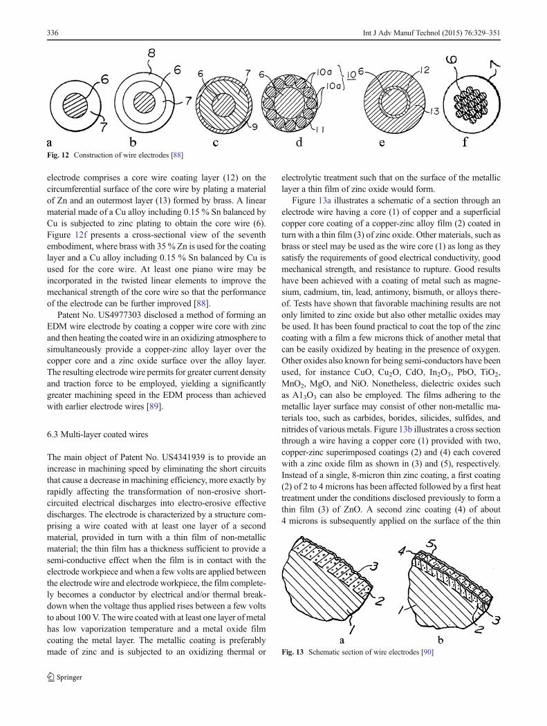
electrode comprises a core wire coating layer (12) on thecircumferential surface of the core wire by plating a materialof Zn and an outermost layer (13) formed by brass. A linearmaterial made of a Cu alloy including 0.15 % Sn balanced byCu is subjected to zinc plating to obtain the core wire (6).Figure 12f presents a cross-sectional view of the seventhembodiment, where brass with 35% Zn is used for the coatinglayer and a Cu alloy including 0.15 % Sn balanced by Cu isused for the core wire. At least one piano wire may beincorporated in the twisted linear elements to improve themechanical strength of the core wire so that the performanceof the electrode can be further improved [88].
Patent No. US4977303 disclosed a method of forming anEDM wire electrode by coating a copper wire core with zincand then heating the coated wire in an oxidizing atmosphere tosimultaneously provide a copper-zinc alloy layer over thecopper core and a zinc oxide surface over the alloy layer.The resulting electrode wire permits for greater current densityand traction force to be employed, yielding a significantlygreater machining speed in the EDM process than achievedwith earlier electrode wires [89].
6.3 Multi-layer coated wires
The main object of Patent No. US4341939 is to provide anincrease in machining speed by eliminating the short circuitsthat cause a decrease in machining efficiency, more exactly byrapidly affecting the transformation of non-erosive short-circuited electrical discharges into electro-erosive effectivedischarges. The electrode is characterized by a structure com-prising a wire coated with at least one layer of a secondmaterial, provided in turn with a thin film of non-metallicmaterial; the thin film has a thickness sufficient to provide asemi-conductive effect when the film is in contact with theelectrode workpiece and when a few volts are applied betweenthe electrode wire and electrode workpiece, the film complete-ly becomes a conductor by electrical and/or thermal break-down when the voltage thus applied rises between a few voltsto about 100V. Thewire coatedwith at least one layer of metalhas low vaporization temperature and a metal oxide filmcoating the metal layer. The metallic coating is preferablymade of zinc and is subjected to an oxidizing thermal or
electrolytic treatment such that on the surface of the metalliclayer a thin film of zinc oxide would form.
Figure 13a illustrates a schematic of a section through anelectrode wire having a core (1) of copper and a superficialcopper core coating of a copper-zinc alloy film (2) coated inturn with a thin film (3) of zinc oxide. Other materials, such asbrass or steel may be used as the wire core (1) as long as theysatisfy the requirements of good electrical conductivity, goodmechanical strength, and resistance to rupture. Good resultshave been achieved with a coating of metal such as magne-sium, cadmium, tin, lead, antimony, bismuth, or alloys there-of. Tests have shown that favorable machining results are notonly limited to zinc oxide but also other metallic oxides maybe used. It has been found practical to coat the top of the zinccoating with a film a few microns thick of another metal thatcan be easily oxidized by heating in the presence of oxygen.Other oxides also known for being semi-conductors have beenused, for instance CuO, Cu2O, CdO, In2O3, PbO, TiO2,MnO2, MgO, and NiO. Nonetheless, dielectric oxides suchas A13O3 can also be employed. The films adhering to themetallic layer surface may consist of other non-metallic ma-terials too, such as carbides, borides, silicides, sulfides, andnitrides of various metals. Figure 13b illustrates a cross sectionthrough a wire having a copper core (1) provided with two,copper-zinc superimposed coatings (2) and (4) each coveredwith a zinc oxide film as shown in (3) and (5), respectively.Instead of a single, 8-micron thin zinc coating, a first coating(2) of 2 to 4 microns has been affected followed by a first heattreatment under the conditions disclosed previously to form athin film (3) of ZnO. A second zinc coating (4) of about4 microns is subsequently applied on the surface of the thin
Fig. 12 Construction of wire electrodes [88]
Fig. 13 Schematic section of wire electrodes [90]
336 Int J Adv Manuf Technol (2015) 76:329–351

oxide film (3), followed by a second heat treatment similar tothe first, providing a thin film (5) of ZnO onto the surface ofthe second zinc coating (4). With the structure in Fig. 13b, thesame phenomena of copper diffusion into zinc and vice versahave been observed, together with coating porosity resultingin outer surface irregularities and roughness [90]. An electrodewire with multi-coated layers for EDM that is capable ofrapidly and precisely machining a workpiece into a desiredshape without changing the electrode wire was disclosed inUS Patent 20080245773. The wire has at least two coatinglayers including an outer layer made of zinc for precisionmachining and a lower layer made of zinc alloy for fastmachining, thereby machining a workpiece continuouslywithout change thereof (Fig. 14).Moreover, the electrode wirecan be manufactured at a relatively low cost. Also, whendischarging for machining a workpiece, no debris separatesfrom the core wire so the machining work is not interrupted bythe electrode wire [91]. US Patent No. US5196665-93 wasanother attempt to improve the mechanical strength of elec-trodes while maintaining benefits such as heat shield effectand the elimination of short circuits. The core is covered witha film of multiple, fine layers. The layers are characterized byhigh electrical conductivity and low melting and vaporizationtemperatures in an alternating fashion. The alternating wireelectrode layers may diffuse into one another in order toproduce alloys of desired structure and composition. The core,which is a metal selected from the group consisting of copper,brass, steel, or copper clad steel, is covered with superimposedalternate layers of copper and a metal selected from the groupconsisting of zinc and zinc alloys containing 30 to 60 % zinccontent with thickness less than 0.5 microns [92]. Patent No.EP0734805A1 and Patent No. US5721414 produced an elec-trode wire having a thicker surface layer of diffused copper-zinc alloy by thermal diffusion method, such that spark ero-sion machining was accelerated [93]. The surface of the wireobtained in accordance with the invention is just roughenough for spark erosion, thus requiring no mechanical sur-face treatment apart from sizing. The wire electrode is char-acterized as comprising a core (17) of copper or copper alloymade up of a central core (19) covered with an upper layer(18) of copper or copper alloy that itself covers the surfacelayer (20) of diffused copper and zinc alloy or copper alloy.
Surface layer (20) has a slightly granular surface (21) asshown diagrammatically in Fig. 15.
7 Diffusion-annealed coated wires
If zinc has such great flushability, it would be presumed that apure zinc coating would produce the ultimate wire. In theoryperhaps, but in reality it does not quite work out that way. Thisis because zinc has a low melting point, and it is only platedonto the surface of the core wire, and the intensity of the sparkdischarge tends to blast the zinc off the wire core surfacebefore it has a chance to live up to its full potential [94].Thus, a coating with high zinc content and relatively highmelting point will result in good adhesion to the core wire. Allthese effects can be achieved by heat-treating the zinc-coatedwire, a process called diffusion annealing. Under the rightconditions at a controlled, elevated temperature and an inertgas environment, diffusion will occur. Diffusion is the processwhereby atoms diffuse from areas of high concentration toareas of lower concentration. The zinc atoms diffuse into thebrass, and the copper atoms from the brass diffuse into thezinc. This diffusion process transforms the zinc coating into ahigh-zinc brass alloy which is zinc-rich, has a relatively highmelting point, and is metallurgically bonded to the corematerial [95, 96].
7.1 Alpha phase wires
The brass alloy phases commonly applicable to EDM wiresare alpha phase, beta phase, gamma phase, and epsilon phase,as shown in Fig. 16. Alpha phase has the highest melting point(approximately 910 °C at its highest commercially feasiblezinc content of 35–39 wt%); beta phase has the next highestmelting point (approximately 890 °C in a diffusion-annealedcoating with a typical 40–53 wt% zinc content); gamma phasehas the next melting point (approximately 800 °C in adiffusion-annealed coating with a typical 57–70 wt% zinccontent); and epsilon phase has the lowest melting point(approximately 550 °C in a diffusion-annealed coating witha typical 85 wt% zinc content) [97, 98].
Fig. 14 Cross section of wireelectrodes [91]
Int J Adv Manuf Technol (2015) 76:329–351 337

7.2 Beta phase wires
The X-type wire was the first diffusion-annealed wire com-monly known as SWX, BroncoCut-X, BetaCut-X, X-Kut, orother brand names. The wire consists of a beta brass coatingover a pure copper core (Fig. 17a). It has the advantage ofcombined high copper conductivity and coherent zinc-richcoating. Its disadvantages are tensile strength equivalent tohalf hard brass combined with poor straightness and high costrelative to brass wires. However, it produces significant pro-ductivity gain in aerospace alloys such as Inconel andTitanium [99, 100].
D-type wire, shown in Fig. 17b, was the second diffusion-annealed wire generally known as CobraCut-D, D-Kut, andother brand names. The wire consists of a beta brass coatingover a copper core alloyed with 20 % zinc. It has the advan-tage of combined improved conductivity of the 80 % Zn to20 % copper core, a coherent zinc-rich coating, and relativelyhigh tensile strength (800N/mm2). Its disadvantage is the highcost. This wire produces significant productivity gain in vir-tually all materials and on many different machines [30].
US patent No. US4935594-90 entails a wire electrode witha structural composition, whereby in its outer coating there is
much greater resistance with respect to erosive wear than thecommon eroding electrode. It was disclosed that the outerlayers of a coated wire have a zinc-rich alloy.
Referring to Fig. 18, making an eroding electrode accord-ing to the invention, a core (2) of 0.1- to 0.6-mm diameter canbe used as an initial material. Onto the core, an originalmaterial coat (3) (Fig. 18a) is applied, consisting of zinc,cadmium, bismuth, antimony, or an alloy of these metals.Such a wire (1) is annealed at 700–850 °Cmost advantageous-ly while passing through a protective gas and is subsequentlycooled off to less than 80 °C—again using a protective gas. Inthis manner, an altered coating (3’) (Fig. 18b) with the afore-mentioned advantageous characteristics is produced. The core(2) of the wire (1’) consists favorably of electrolytic copperhaving more than 99 wt% copper and very low oxygencontent. A copper-zinc-alloy with 79.5–80.5 wt% Cu, theremainder being Zn, can also beneficially be used. The alteredcoating (3’) includes layers of a mixed structure of metallicphases, and its content of low volatilization temperature metaldecreases as the altered coating (3’) extends from its outersurface to the core (2). The metallic phase layers includealpha-beta phases and beta-gamma phases [99].
European Patent No. EP0526361A1 introduced an elec-trode to obtain high-stability electric discharge while machin-ing an object. A layer of Zn is formed on a copper or copper-alloy wire. The wire is heat-treated at a temperature below thebeta prime-beta transition temperature of the binary alloy Cu-Zn until an outer layer (31) consisting of a homogeneous betaprime phase is formed. Then, the wire is drawn at a drawingratio greater than 100 % in order to obtain an electrode (1) asshown in Fig. 19. Electrodes for electro-erosion have an outermetal layer (3) made of Cu-Zn alloy in the homogeneous betaprime phase free of oxide inclusions with a junction (32) oflow thickness. The wire (20) is made of copper or copper alloydoped with one or more elements selected from Fe, Co, Ti, P,Mg, Cr, Zr, Si, at a global content between 0.1 and 1 wt% orwith one or more elements selected from Al, Sn, Ni up to4 wt% overall. The outer metal layer (3) has a Zn weightconcentration in the region of 46.5 % +/−1, substantiallyconstant throughout its thickness [96].
In Patent No. US5858136, copper wire coated with a layerof zinc is heated to 750 °C, sufficient for the formation of abrass beta phase. The temperature is maintained until zinccompletely diffuses, as shown in Fig. 20a. The wire is thenheated to a temperature of 950 °C, which is necessary for theformation of a brass phase, and the central copper part of thewire transforms into a brass alpha phase (Fig. 20b). It has theadvantage of both high conductivity and relatively high tensilestrength [100].
Patent No. US7687738 concerns an electrode wire com-prising an unalloyed copper core coated with a diffused zincalloy with thickness greater than 10 % of the wire diameter.The coating layer is optionally plated with a thin Zn, Cu, Ni,
Fig. 15 Diagram of wire electrode [93]
Fig. 16 Cu-Zn phase diagram [97]
338 Int J Adv Manuf Technol (2015) 76:329–351

Si, or Au surface contact film. In all cases, an increase in thespark erosion rate of approximately 30 % was observed com-pared to a brass or zinc-plated brass wire of the same diameter.A second aspect of the invention highlights the influence ofthe overall conductivity of the electrode wire on spark erosionperformance, exploiting this influence to increase the machin-ing rate on the assumption that electrical energy will besupplied by more and more powerful generators. It has beenobserved that the overall electrical conductivity of the elec-trode wire may advantageously range from 65 to 75 % IACS.Below 65 % IACS optimum spark erosion, cutting perfor-mance is not achieved because of the insufficient conductivityof the electrode wire. The wire breaks more easily as a resultof heating in the sparking area. This is caused by the moreintense Joule effect and by the reduced cooling associatedwith lower thermal conductivity. The required type of elec-trode wire cannot be obtained above 75 % IACS, because itwould then be obligatory to reduce the thickness of the dif-fused layer to under 10 % of the electrode wire diameter.Failing this, the wire is too rigid and brittle and must not bedrawn during fabrication. The recommended overall electricalconductivity of the electrode wire is in the order of 69 %IACS, corresponding to a diffused layer approximately 35 pmthick for a 0.33-mm electrode wire, i.e., a relative thickness ofapproximately 11 %. The relative thickness of 11 % and
overall electrical conductivity value of 69 % IACS yield goodresults for wires ranging in diameter from approximately 0.20to 0.35 mm [101].
7.3 Gamma phase wires
Gamma phase brass has higher zinc content than beta phasebrass. Gamma phase brass is very brittle; therefore, the gammacoating thickness is usually limited to less than 5 microns;thicker coatings will fracture and strip off in the final drawingprocess. Due to the brittleness, the gamma phase brass actu-ally fractures during the final drawing process producing asomewhat discontinuous surface. Such surface has the benefitof increasing the cutting speed by improving flushing as thewire passes through the cut, enhancing water flow and scour-ing debris from the gap. The discontinuous surface has thedisadvantage of being slightly dirtier than other zinc-coatedwires [91].
Gamma brass-type wire features a brass core and a gammaphase brass outer layer, and it is commonly known as Z-Kut,Topaz, Gamma-Z, DeltaCut, and other trade names. It issimilar to zinc-coated brass wire, except that the pure zinccoating is replaced by a gamma phase brass coating as shownin Fig. 21a. It is available with both hard and half hard brasscores. Performance is typically 10 to 25 % faster than pure
Fig. 17 X- and D-type wireelectrodes [30]
Fig. 18 Cross section of wireprior to and after the process [99]
Int J Adv Manuf Technol (2015) 76:329–351 339

zinc-coated wires [30]. According to the embodiments ofinvention No. US6566622 B1, the wire electrode core madeof copper (X-type wire) or copper alloy (D-type wire) is firstdiffusion heat-treated so a beta phase forms, after whichstabilization treating steps are performed in order to producethe outer coating of the gamma phase (Fig. 21b, c) [102]. Itcan be used in the same range of applications as traditional Xand D wire types, but this offers enhanced performance ofapproximately 10 % [103]. It has been reported that diffusion-annealed beta phase brass contains zinc content in the range of45–50 % and has a high melting point, thereby exhibitingexcellent tenacity. Gamma wire has the advantage of a low-cost method of distributing a layer of gamma phase over thewire electrode surface. These wires have the capability ofreducing cycle time by lowering the cost of rough cuts viaincreased removal rate [104]. Many attempts have been madeto improve gamma-coated wires by employing low-temperature diffusion annealing owing to changes in technol-ogy disclosed by various inventors [88, 86]. A range ofinventors have also tried to cover the conductive core with afilm of multiple fine layers. The alternating coating layers onthe core of the wire electrode are diffused into one another inorder to obtain alloys of desired structure and composition.These wires have the characteristics of high conductivity andlow melting and vaporization in an alternating fashion[105–107]. Cladding surface passivation of the brittle gammacoating phase appears to reinforce resistance against corrosion[108].
It was disclosed that the coating in US Patent No.US5945010-97 is comprised of a copper-zinc gamma phasealloy or a nickel-zinc alloy. The core may contain copper,
copper clad steel, brass, or other suitable materials. The sec-ond coating metal may consist of a metal selected from thegroup including Zn, Mg, and Al by employing low-temperature diffusion anneals. The resulting EDM wireachieves faster and better surface finish than conventionalEDM wire electrodes. A further advantage of US Patent No.945010-99 is that the higher zinc content in the coatingcompared to the earlier US Patent No. 5945010-97 will resultin significantly lower volumetric heat of sublimation for thecoating and therefore cause the wire to flush more efficientlywhile having enough tenacity to survive the EDM erosionprocess. The tensile strength rises very rapidly with the ap-pearance of the beta phase. At 32 % zinc content, the tensilestrength of brass reaches a maximum when alpha and betaphases are present in approximately equal proportion [106].Keeping the above aspect in view, the present invention,Patent No. EP0799665A1 and Patent No. US5808262, ismeant to produce a spark erosion electrode, the core of whichis of comparatively low zinc alpha brass with a top layer ofhighly rich zinc beta and gamma brass to facilitate betterflushability of the electro-erosion process and also to achievecomparatively higher tensile strength of the electrode corematerial [109].
Patent No. US2011/0290531A1 relates to a wire electrode(1,1’) for electric discharge cutting processes. The wire elec-trode (1,1’) has a core (2) containing a metal or metal alloy,and a coating (3, 4; 3, 4, 5), at least one (3) of which contains aphase mixture of beta brass or beta prime brass and gammabrass as shown in Fig. 22. The beta phase or beta prime phaseand the gamma phase are arranged next to each other in a fine-grained structure in which the mean size of the beta brass or
Dep
osit
ing
Zn
Heat
Tre
atm
en
t
Pre
ssin
g a
nd
dra
win
g
Fig. 19 Shows the different stepsof the process according to theinvention [96]
Fig. 20 Shows different wires with different coated thickness [100]
340 Int J Adv Manuf Technol (2015) 76:329–351

beta prime brass grains and the gamma brass grains amountsto a maximum of 5 microns relative to the cross section ofthe wire electrode (1, 1’). In the preferred embodimentaccording to Fig. 22b, a core (2) is formed from Cu-Zn20%; the covering layer (4) which adjoins the core isformed predominantly from beta or beta prime brass hav-ing a zinc content of about 45 wt%; the covering layer (3)is formed principally from a phase mixture of beta or betaprime brass and gamma brass having a mean zinc contentof about 53 wt%; the top layer (5) consists primarily ofzinc oxide. The wire electrode (1’) has a tensile strength ofabout 750 N/mm2 and electrical conductivity of about17 m/Ωmm2 [110].
Patent No. US8338735 comprises a brass core (1) coveredwith a gamma phase brass coating (2) having a structurefragmented into blocks (2a) between which the core (1) isexposed. The blocks (2a) have a thickness E2 with a narrowdistribution and cover the core (1) according to a coverage rategreater than 50 % as shown in Fig. 23. This produces regularfragmentation of the coating, which improves the finish stateof the machined parts [111].
US Patent No. 5762726-98 is recognized for higher zinccontent phases in the copper-zinc system, specifically thegamma phase, which would be more desirable for EDM wireelectrodes. It has even better cutting capacity than a wire
electrode with a sheath layer consisting of a pure beta phase.The choice of a pure gamma phase, to which hard inertmaterials are added where appropriate, has proved even moreadvantageous than the beta phase in terms of cutting behavior.With conventional processes, that is to say longtime diffusion,it is scarcely possible to produce such a gamma phase in pureform. As a rule, a mixed structure with fractions of alpha, beta,and/or gamma phases is obtained. Figure 24a represents thestarting material, which consists of a core of alpha brass and asheath layer of zinc (eta zinc). After heating has taken placeand following the shortest possible holding time, an epsilonzinc layer forms in the region between the core and sheathlayer (Fig. 24b), the eta zinc layer transforms into an epsilonzinc layer during increasing annealing time and thereforediffusion increases (Fig. 24c). It is possible to see in Fig. 24cthat a narrow layer, especially a gamma brass layer, forms inthe transitional region between the core and epsilon zinc layerwhile annealing time continues. The gamma brass layer ex-pands so that the epsilon zinc layer is transformed into a
Brass Core(80%Cu/20%Zn)
Gamma Phase 65%Zn/35%Cu
Copper Core
Gamma Phase 65%Zn/35%Cu
Brass Core(65%Cu/35%Zn)
Gamma Phase 65%Zn/35%Cu
Fig. 21 Gamma phase wire electrodes [30]
Fig. 22 Schematic cross section of wire [110] Fig. 23 Large-scale diagrammatic view in cross section wire [111]
Int J Adv Manuf Technol (2015) 76:329–351 341
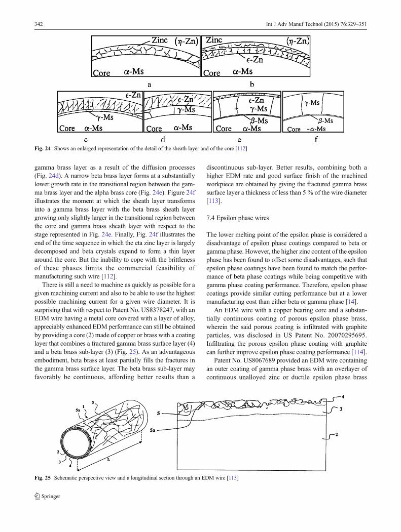
gamma brass layer as a result of the diffusion processes(Fig. 24d). A narrow beta brass layer forms at a substantiallylower growth rate in the transitional region between the gam-ma brass layer and the alpha brass core (Fig. 24e). Figure 24fillustrates the moment at which the sheath layer transformsinto a gamma brass layer with the beta brass sheath layergrowing only slightly larger in the transitional region betweenthe core and gamma brass sheath layer with respect to thestage represented in Fig. 24e. Finally, Fig. 24f illustrates theend of the time sequence in which the eta zinc layer is largelydecomposed and beta crystals expand to form a thin layeraround the core. But the inability to cope with the brittlenessof these phases limits the commercial feasibility ofmanufacturing such wire [112].
There is still a need to machine as quickly as possible for agiven machining current and also to be able to use the highestpossible machining current for a given wire diameter. It issurprising that with respect to Patent No. US8378247, with anEDM wire having a metal core covered with a layer of alloy,appreciably enhanced EDM performance can still be obtainedby providing a core (2) made of copper or brass with a coatinglayer that combines a fractured gamma brass surface layer (4)and a beta brass sub-layer (3) (Fig. 25). As an advantageousembodiment, beta brass at least partially fills the fractures inthe gamma brass surface layer. The beta brass sub-layer mayfavorably be continuous, affording better results than a
discontinuous sub-layer. Better results, combining both ahigher EDM rate and good surface finish of the machinedworkpiece are obtained by giving the fractured gamma brasssurface layer a thickness of less than 5 % of the wire diameter[113].
7.4 Epsilon phase wires
The lower melting point of the epsilon phase is considered adisadvantage of epsilon phase coatings compared to beta orgamma phase. However, the higher zinc content of the epsilonphase has been found to offset some disadvantages, such thatepsilon phase coatings have been found to match the perfor-mance of beta phase coatings while being competitive withgamma phase coating performance. Therefore, epsilon phasecoatings provide similar cutting performance but at a lowermanufacturing cost than either beta or gamma phase [14].
An EDM wire with a copper bearing core and a substan-tially continuous coating of porous epsilon phase brass,wherein the said porous coating is infiltrated with graphiteparticles, was disclosed in US Patent No. 20070295695.Infiltrating the porous epsilon phase coating with graphitecan further improve epsilon phase coating performance [114].
Patent No. US8067689 provided an EDM wire containingan outer coating of gamma phase brass with an overlayer ofcontinuous unalloyed zinc or ductile epsilon phase brass
Fig. 24 Shows an enlarged representation of the detail of the sheath layer and of the core [112]
Fig. 25 Schematic perspective view and a longitudinal section through an EDM wire [113]
342 Int J Adv Manuf Technol (2015) 76:329–351

entrapping the gamma phase, thereby filling in any disconti-nuities and thus presenting a workpiece surface with homo-geneous electrical properties (Fig. 26). For rough cuts wherespeed is of utmost interest and accuracy is of lesser impor-tance, any zinc or epsilon phase brass covering the underlyinggamma phase brass alloy particles will quickly be consumedbecause, it will be proportionately thinner than that filling thegaps between the gamma particles, thereby giving evidence ofhigh-performance gamma coating. Referring to Fig. 26a, ahigh brass core (12) is covered with a zinc coating (15) with aninitial thickness of 10 pm. After heat treatment at 1,700 °C for6 h in a nitrogen atmosphere, the wire is depicted in Fig. 26b,with a gamma phase brass coating (18) on the high brass core(12). Since a non-oxidizing atmosphere of nitrogen gas wasemployed during the heat treatment, the wire can beelectroplated again with a zinc coating (15) 10 pm thick asdepicted in Fig. 26c. Cold drawing the composite wire to itsfinal diameter of 0.25 mm causes the brittle gamma phase tofracture and form discrete particles (19) as portrayed inFig. 26d. However, the zinc coating (16) is sufficiently ductileto flow around these particles and encapsulate them on thehigh brass core (12). According to the invention, the coresubstrate preferably includes copper at or near its outer sur-face. Thus, a variety of substrate materials are contemplatedfor the present invention, including, but not limited to, purecopper, brass, brass on copper, copper clad steel, brass oncopper clad steel, brass clad steel, and brass on brass (e.g.,high zinc content brass on lower zinc content brass) [115].
8 Steel wires
Evidently, due to electric discharge, a force opposite to themachining direction is created on the machined sections of thewire electrode. Electrostatic and electromagnetic forces arealso created on the wire electrode. On account of all theseforces as well as the wire vibrations, the actual wire position
differs from the programmed position. This leads to accuracyand precision problems [116–119]. Deviation from the pro-grammed outline at the corners leads to obtaining roundcorners instead of the desired sharp corners [120].Consequently, plain molybdenum or tungsten wires formdue to the high tensile strength (>1,900 MPa) [121, 33].Owing to the drawback of being expensive and having poorflushability, a new type of wire was developed that comprisesa high-strength pearlite steel wire with over 0.06 % carboncontent and a coating of copper-free zinc or zinc alloy coating.As a result, improved precision and accuracy with increasedmechanical load is achieved [91, 14].
8.1 Molybdenum wire
This type of wire is used in limited applications which requirevery high tensile strength to provide a reasonable load carry-ing capacity in small-diameter wires. Moly wire has both highmelting point and high tensile strength. It is often used forsmall diameter EDM wires of 0.1 mm and under.Unfortunately, Moly wire has both low electrical conductivityand very low flushability. In addition, it is very abrasive topower feeds and wire guides and is often difficult to autothread. Finally, Moly wire is very expensive [122, 30].
8.2 Tungsten wire
Tungsten wire has greater tensile strength and melting pointthan Moly wire. Tungsten wire is often an economical alter-native to Moly wire in diameters of 0.05 mm and smaller. Inhigh-precision work on wire EDMmachines, tungsten wire ispreferred, as it requires small inside radii in the range of0.025–0.1 mm. Since brass and coated wires are not practicaldue to their low load-carrying capacity in these sizes, molyb-denum and tungsten wires are used. However, because of thelimited conductivity, high melting point, low vapor pressurerating, and slow cutting tendency, it is not suitable for verythick work [122, 123].
Fig. 26 Cross-sectional view of development wire [115]
Int J Adv Manuf Technol (2015) 76:329–351 343

8.3 MolyCarb wire
A composite wire called MolyCarb offers significant advan-tages for small-diameter work. Moly wire is coated with amixture of graphite and Molybdenum oxide, thus improvingits flushing characteristics [124, 30].
8.4 Steel core wires
For optimum machining performance, EDM wire electrodesmust have good electrical conductance, which enables highmachining current to flow through the electrode. They mustalso have highmechanical strength for increased traction forcethrough the machining zone.
Steel core wire, containing a steel core, is commonlyknown as Compeed, MicroCut, MacroCut, or other tradenames. The steel core in this wire type offers exceptionaltensile strength and ductility, and there is a copper intermedi-ate layer to provide conductivity besides a beta phase brassouter layer (Fig. 27). Steel core wire exhibits exceptionalresistance to breakage for tall workpieces, interrupted cuts,or poor flushing conditions, all while providing excellentperformance. Its primary limitations are high cost, straightnessissues, autothreadability, and possible damage to scrap chop-pers due to the steel core [75, 30, 113].
In order to reap the benefits of the wire electrode with a firstcopper coating on steel wire and then plating with a coating ofzinc, cadmium, tin, lead, antimony, bismuth, or alloys thereof,US Patent 4287404-1981 was developed [85]. The objectiveof this invention is to provide an electrode which greatlyfacilitates electrical discharge triggering and which decreasesany tendency to cause short circuits. The result would be thatthe wire electrode of this invention enables machining athigher speeds than with conventional wire electrodes. Also,Korean Patent No. 10-1-0009194 and US Patent NO.US20080245773 represent a wire electrode for electrical dis-charge machining, which includes a steel core coated with
copper or other components, and a copper-zinc alloy layer ofCuZn10-CuZn50 coated onto the steel core [91]. US PatentNo. US4686153-87 provides an electrode wire with a coreincluding a steel wire coated with copper or another conduc-tive material as well as a surface coating layer of zinc or thelike. The average concentration of zinc in the copper-zincalloy layer should preferably be less than 50 wt% but not lessthan 10 wt%.
Referring to Fig. 28, an electrode wire (10) comprises acopper clad steel wire (13) including a steel core wire (11)covered with a copper coating layer (12) of uniform thicknessand a copper-zinc alloy layer (14) of generally uniform thick-ness ranging from 0.1 to 15 microns [95]. The wire electrodeof US Patent No. 4998552-91 has a coremade of steel, a lowerlayer made of homogeneous copper (Cu of 100 %) and anupper brass layer including 50 wt% zinc. The steel core issurrounded by copper or copper alloy to form a multi-layerstructure, thereby having relatively great mechanical strength[14]. US patent No. 6875943-2005 represents a high-strengthpearlitic steel wire having carbon content higher than 0.6 %and tensile strength higher than 3,000 MPa. The steel wire iscoated with copper-free zinc or zinc alloy coating. The elec-trode is particularly suitable for high-precision performanceapplications.
Alternatively, a steel strip may be used as shown inFig. 29b. If wires with a circular cross section are used asseen in Fig. 29a, the diameter is preferably lower than0.35 mm and even more preferably lower than 0.25 mm, forexample 0.1, 0.07, or 0.03 mm. Wires with thickness below0.25 mm, for instance 0.1 mm, 0.05 mm, or 0.02 mm, can beconsidered flat wires. The high strength pearlitic steel coreperforms the strength function while the zinc or zinc alloycoating performs the heat dissipation and machining func-tions. In one embodiment, the zinc alloy is a zinc aluminumalloy. Such zinc aluminum alloy ideally comprises between 2and 10 % Al. Between 0.1 and 0.4 % of a rare earth elementsuch as La and/or Ce can be added. An intermediate layer ispossibly applied between the steel and zinc or zinc alloy layer.Such intermediate layer can be aluminum or silver or it can
Beta Phase 50%Zn/50%Cu
Steel Core
Fig. 27 Steel core wire [30] Fig. 28 Sectional view of the electrode wire [95]
344 Int J Adv Manuf Technol (2015) 76:329–351
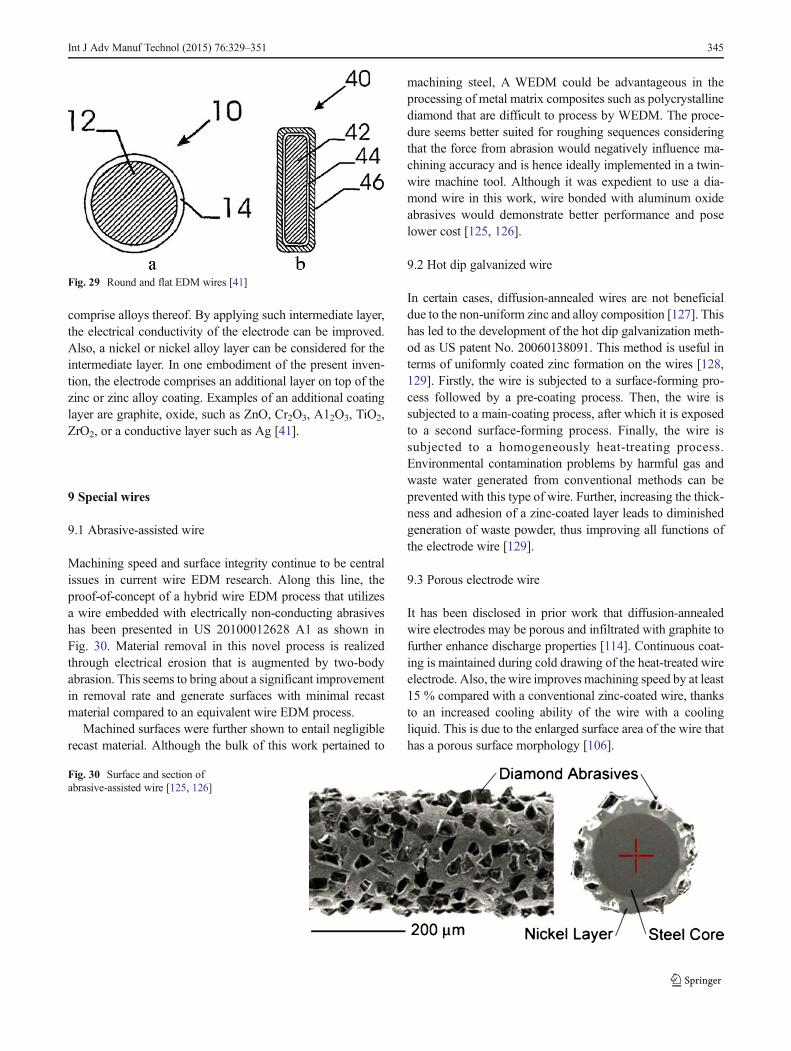
comprise alloys thereof. By applying such intermediate layer,the electrical conductivity of the electrode can be improved.Also, a nickel or nickel alloy layer can be considered for theintermediate layer. In one embodiment of the present inven-tion, the electrode comprises an additional layer on top of thezinc or zinc alloy coating. Examples of an additional coatinglayer are graphite, oxide, such as ZnO, Cr2O3, A12O3, TiO2,ZrO2, or a conductive layer such as Ag [41].
9 Special wires
9.1 Abrasive-assisted wire
Machining speed and surface integrity continue to be centralissues in current wire EDM research. Along this line, theproof-of-concept of a hybrid wire EDM process that utilizesa wire embedded with electrically non-conducting abrasiveshas been presented in US 20100012628 A1 as shown inFig. 30. Material removal in this novel process is realizedthrough electrical erosion that is augmented by two-bodyabrasion. This seems to bring about a significant improvementin removal rate and generate surfaces with minimal recastmaterial compared to an equivalent wire EDM process.
Machined surfaces were further shown to entail negligiblerecast material. Although the bulk of this work pertained to
machining steel, A WEDM could be advantageous in theprocessing of metal matrix composites such as polycrystallinediamond that are difficult to process by WEDM. The proce-dure seems better suited for roughing sequences consideringthat the force from abrasion would negatively influence ma-chining accuracy and is hence ideally implemented in a twin-wire machine tool. Although it was expedient to use a dia-mond wire in this work, wire bonded with aluminum oxideabrasives would demonstrate better performance and poselower cost [125, 126].
9.2 Hot dip galvanized wire
In certain cases, diffusion-annealed wires are not beneficialdue to the non-uniform zinc and alloy composition [127]. Thishas led to the development of the hot dip galvanization meth-od as US patent No. 20060138091. This method is useful interms of uniformly coated zinc formation on the wires [128,129]. Firstly, the wire is subjected to a surface-forming pro-cess followed by a pre-coating process. Then, the wire issubjected to a main-coating process, after which it is exposedto a second surface-forming process. Finally, the wire issubjected to a homogeneously heat-treating process.Environmental contamination problems by harmful gas andwaste water generated from conventional methods can beprevented with this type of wire. Further, increasing the thick-ness and adhesion of a zinc-coated layer leads to diminishedgeneration of waste powder, thus improving all functions ofthe electrode wire [129].
9.3 Porous electrode wire
It has been disclosed in prior work that diffusion-annealedwire electrodes may be porous and infiltrated with graphite tofurther enhance discharge properties [114]. Continuous coat-ing is maintained during cold drawing of the heat-treated wireelectrode. Also, the wire improves machining speed by at least15 % compared with a conventional zinc-coated wire, thanksto an increased cooling ability of the wire with a coolingliquid. This is due to the enlarged surface area of the wire thathas a porous surface morphology [106].
Fig. 29 Round and flat EDM wires [41]
Fig. 30 Surface and section ofabrasive-assisted wire [125, 126]
Int J Adv Manuf Technol (2015) 76:329–351 345

Patent No. US6482535 relates to a porous electrode wirefor use in EDM, as shown in Fig. 31. The purpose of theinvention is to provide a coated wire for EDM with improvedmachining speed by increasing the surface area and inner partof the wire. The inner part will be in contact with a coolingliquid so as to increase the wire’s cooling ability. Therefore,the steps to achieve the above-mentioned purposes are asfollows: provide a wire with an initial diameter made of a firstmetal; hot dip galvanize the wire by passing it for a desirableamount of time through a molten second metal with lowervaporization temperature than the first metal; form an alloylayer by the diffusion reaction between the first and secondmetals, the second metal has higher hardness and less elonga-tion than the first metal and a coating layer made of the secondmetal; finally, draw the wire with the alloy and coating layersto form a second diameter, thereby forming cracks in the alloyand coating layers due to the high hardness and low elonga-tion of the alloy layer. At this time, copper or brass having 63–67 wt% copper and 33–37 wt% zinc may be added to the firstmetal. Furthermore, zinc, aluminum, or tin may be used in thesecond metal. The porous nature of the wire arises from thecracks in the alloy and coating layers during the drawing step[130].
10 Discussion and future trends
After a thorough investigation of the published works in thisfield, the following conclusions can be drawn.
& The development of economical wire electrodes with highconductivity and elevated fracture toughness for high-speed cutting will remain a key research area.
& Few efforts have been made to identify electrode mate-rials, keeping in view their thermal properties from theperspective of cutting speed [131, 132].
& Preventing wire from rupture has an edge over improvingmachining efficiency of the WEDM process. Wire
breakage and wire flaking during machining have alsorestricted accuracy and efficiency, which subsequentlyaffect the overall productivity of the WEDM process[133–136].
& Few studies have been conducted on measuring the tem-perature distribution of wire and the influence of non-uniform temperature fields on the vibration and stabilitycharacteristics of EDM wires [137–140].
& Very little work has been reported on finding changes inthe mechanical properties and surface integrity ofWEDM-worked material. Therefore, this area is still openfor future research work [141–143].
& Not many studies have been conducted on the machiningof ceramics like ZrO2 and Al2O3 by using assisting elec-trodes to facilitate sparking of these highly electricallyresistive materials [144–146].
& The advent of newer and more interesting materials thatare productive in a wide variety of applications has chal-lenged the feasibility of future manufacturing environ-ments. Higher zinc content leads to faster cutting, butresults are sometimes achieved only when machine set-tings are optimized. Optimized settings for WEDM arenecessary to achieve the performance attainable with next-generation wires [147–152].
& Developing wires with smaller diameters and improvedwire guides for fine wires to handle small workpieces is achallenge for future manufacturers.
& More research and experimentation is required to enhancecutting efficiency with new combinations of core andcoating materials, since existing wires do not fulfill allrequirements. High-performance wire electrodes withhigh conductivity alloy materials for high-speed cuttingapplications will be extensively used for automobile partsand die manufacturing in the future [11].
& The surface generated in dry WEDM with high-performance wire electrodes was studied [153–155].
& An attempt has been made in prior work to develop a new,high-performance wire with a core of pure aluminum andcoating of alpha brass and gamma brass, but with the
Fig. 31 Photograph of a porouscoated wire showing the surfacemorphology and the cross section[130]
346 Int J Adv Manuf Technol (2015) 76:329–351
limitation that tensile strength is less than that of plainbrass wire [156].
& Skin effect problems caused by steel-cored wire electrodesare resolved by coating brass/copper with a thick layer,which ends in performance similar to that of brass wire.Smaller-diameter wires that do not need thick coatingresult in good cutting efficiency.
11 Conclusions
The focus of this paper was on the evolving technologies ofEDMwire electrodes from using copper to the widely utilizedbrass wire electrodes and from brass to the latest coated wireelectrodes, which have been developed and assist user de-mand and needs in terms of maximum productivity and quan-tity. Special wire electrodes were introduced as abrasive, hotdip galvanizing, and porous wire electrodes. The copper wireelectrode was replaced by brass owing to the low materialremoval rate and low wear or erosion resistance. The conduc-tivity of brass wires was scarified for strength and betterfusibility. Various metals or alloys with good electrical con-ductance and low vaporization temperature, such as zinc, tin,lead, etc., have been tried to coat wire electrodes againstthermal shock resulting from electrical discharge without run-ning the risk of rupturing the wire. The purpose of graduallychanging the zinc content in coating alloys is to provideenhanced cooling ability and flushability compared to con-ventional brass wire electrodes. Alloy with higher zinc contentleads to increased cutting speed. The layer of pure zinc onbrass wire quickly becomes worn and does not protect the coreof the wire when cutting tall pieces. Zinc has a low meltingpoint, and it can only plate the wire core. As zinc tends to blastoff during sparking, coating with higher zinc content causesgood adhesion to the core wire. This can be achieved bydiffusion annealing the zinc-coated wires. But owing to theirinability to cope with the brittleness of the gamma phasebesides the limited commercial feasibility of manufacturing,these wires have prompted the development of composite wireelectrodes. Gamma phase coatings on a wire core are morebrittle than beta phase coatings, but epsilon phase coatings areeven more brittle than gamma phase. Owing to the limitationof instability of the epsilon phase, the process of convertingzinc coating to epsilon phase is difficult. These high-performance wires significantly increaseWEDM productivityover plain brass wires. The primary limitations of these wiresare high cost, damage to the scrap chopper, straightness issues,and environmental hazards. The authors believe that the chal-lenge faced byWEDMmanufacturers is to continuously pushthe envelope in the area of developing EDM wire electrodesthat have high conductivity, are environmental friendly, andcan undergo unattended machining operations. Achieving
high conductivity and strength without sacrificing fracturetoughness are key research areas.
Acknowledgements This research was funded by the high impactresearch (HIR) grant number: HIR-MOHE-16001-00-D000027 fromthe Ministry of Higher Education, Malaysia, and the Universityof Malaya Postgraduate Research Grant (PPP) Program No.PG020-2013B.
References
1. Kanlayasiri K, Boonmung S (2007) Effects of wire-EDM machin-ing variables on surface roughness of newly developed DC 53 diesteel: design of experiments and regression model. Journal ofMaterials Processing Technology 192–193:459–464
2. Davim JP (2008) Machining fundamentals and recent advances.Springer-Verlag London Limited, British Library Cataloguing inPublication Data. doi:10.1007/978-1-84800-213-5
3. Patil N, Brahmankar PK (2010) Determination of material removalrate in wire electro-dischargemachining of metal matrix compositesusing dimensional analysis. Int J Adv Manuf Technol 51(5-8):599–610. doi:10.1007/s00170-010-2633-3
4. Huang Y, Ming W, Guo J, Zhang Z, Liu G, Li M, Zhang G (2013)Optimization of cutting conditions of YG15 on rough and finishcutting in WEDM based on statistical analyses. Int J Adv ManufTechnol 69(5–8):993–1008. doi:10.1007/s00170-013-5037-3
5. Saha P, Tarafdar D, Pal S, Saha P, Srivastava A, Das K (2009)Modeling of wire electro-discharge machining of TiC/Fe in situmetal matrix composite using normalized RBFN with enhanced k-means clustering technique. Int J AdvManuf Technol 43(1–2):107–116. doi:10.1007/s00170-008-1679-y
6. Mohri N, Fukuzawa Y, Tani T, Sata T (2002) Some considerationsto machining characteristics of insulating ceramics-towards practi-cal use in industry. CIRPAnnals -Manufacturing Technology 51(1):161–164. doi:10.1016/S0007-8506(07)61490-5
7. Muttamara A, Fukuzawa Y, Mohri N, Tani T (2003) Probability ofprecision micro-machining of insulating Si3N4 ceramics by EDM.Journal of Materials Processing Technology 140(1–3):243–247.doi:10.1016/S0924-0136(03)00745-3
8. Kozak J, Rajurkar KP, Chandarana N (2004) Machining of lowelectrical conductive materials by wire electrical discharge machin-ing (WEDM). Journal of Materials Processing Technology 149:266–271
9. Wüthrich R, Fascio V (2005) Machining of non-conducting mate-rials using electrochemical discharge phenomenon—an overview.International Journal of Machine Tools and Manufacture 45(9):1095–1108. doi:10.1016/j.ijmachtools.2004.11.011
10. Motoki M, Summer K (1978) Recent EDM. J Japan Soc ElectricalMachining Engrs 11:2–20
11. Kapoor J, Singh S, Khamba JS (2012) High-performance wireelectrodes for wire electrical-discharge machining—a review.Proceedings of the Institution of Mechanical Engineers, Part B:Journal of Engineering Manufacture 226(11):1757–1773. doi:10.1177/0954405412460354
12. Paul CP, Kumar A, Bhargava P, Kukreja LM (2013) Nontraditionalmachining processes—research advances. Springer-Verlag London.doi:10.1007/978-1-4471-5179-1
13. Ho KH, Newman ST, Rahimifard S, Allen RD (2004) State of theart in wire electrical discharge machining (WEDM). InternationalJournal of Machine Tools and Manufacture 44(12–13):1247–1259.doi:10.1016/j.ijmachtools.2004.04.017
Int J Adv Manuf Technol (2015) 76:329–351 347
14. Kapoor J, Singh S, Khamba JS (2010) Recent developments in wireelectrodes for high performance WEDM. Paper presented at theProceedings of the World Congress on Engineering, London
15. Kwon S, Yang M-Y (2006) The benefits of using instantaneousenergy to monitor the transient state of the wire EDM process. Int JAdv Manuf Technol 27(9–10):930–938. doi:10.1007/s00170-004-2252-y
16. Hargrove SK, Ding D (2007) Determining cutting parameters inwire EDM based on workpiece surface temperature distribution. IntJ Adv Manuf Technol 34(3–4):295–299. doi:10.1007/s00170-006-0609-0
17. Jangra K, Grover S, Aggarwal A (2011) Digraph andmatrix methodfor the performance evaluation of carbide compacting diemanufactured by wire EDM. Int J Adv Manuf Technol 54(5–8):579–591
18. Moulton DB (1999) Wire EDM the fundamentals. SugarGrove, IL: EDM network (www.notebookmanuals .bestmanual guide. Com)
19. El-Hofy H (2005) Advanced machining processes. McGraw-Hill.doi:10.1036/0071466940
20. Sommer C, Sommer S (2005) Complete EDM handbook. AdvancePub
21. Kern R (2008) EDM wire selection. EDM Today:12–1622. Garg R (2010) Effect of process parameters on performance mea-
sures of wire electrical discharge machining. National institute oftechnology, kurukshetra
23. Jangra K, Grover S, Chan FT, Aggarwal A (2011) Digraph andmatrix method to evaluate the machinability of tungsten carbidecomposite with wire EDM. Int J Adv Manuf Technol 56(9–12):959–974
24. Somashekhar K, Ramachandran N, Mathew J (2010) Materialremoval characteristics of microslot (kerf) geometry in μ-WEDMon aluminum. Int J Adv Manuf Technol 51(5–8):611–626. doi:10.1007/s00170-010-2645-z
25. Dauw DF, Albert L (1992) About the evolution of wire tool perfor-mance in wire EDM. CIRP Annals - Manufacturing Technology41(1):221–225. doi:10.1016/S0007-8506(07)61190-1
26. Aoyama S, Tamura K, Sato T, Kimura T, Sawahata K, Nagai T(1999) High-performance coated wire electrodes for high-speedcutting and accurate machining. Hitachi Cable Review 18:75–80
27. Aoyama S (2001) Development of high performance wire electrodefor wire electric discharge machining. J Japan Soc ElectricalMachining Engrs 35:46–51
28. Davis JR (1998) Metals handbook desk edition. 2 edn. ASMInternational Handbook Committee
29. Yan M-T, Huang P-H (2004) Accuracy improvement of wire-EDMby real-time wire tension control. International Journal of MachineTools and Manufacture 44(7–8):807–814. doi:10.1016/j.ijmachtools.2004.01.019
30. Kern R (2013) EDM wire primer. http://www.edmtodaymagazine.com/
31. Gedeon M (2011) Strip Vs wire. Technical Tidbits 3 (11)32. Lin P, Liao T-T (2009) An effective-wire-radius compensation
scheme for enhancing the precision of wire-cut electrical dischargemachines. Int J AdvManuf Technol 40(3–4):324–331. doi:10.1007/s00170-007-1333-0
33. Uhlmann E, Roehner M (2008) Investigations on reduction of toolelectrode wear in micro-EDM using novel electrode materials.CIRP Journal of Manufacturing Science and Technology 1(2):92–96. doi:10.1016/j.cirpj.2008.09.011
34. Groos H (1988) Wire electrode for the spark erosive cutting. US4766280 A
35. Walder G, Balleys F (1999) Wire electrode arrangement forelectroerosive cutting. US 5882490 A
36. Gonnissen D, Van Vooren W (2001) Electric discharge machiningwire. WO Patent 2,001,089,750
37. Inoue K (1983) Electroerosive wire-cutting method and apparatuswith a shaped wire electrode. US 4418263 A
38. Inoue K (1985) Traveling-wire EDM method. US 4508604 A39. Seong K (1999) Method of manufacturing porous electrode wire for
electric discharge machining and structure of the electrode wire.WO Patent 1,999,006,183
40. Groos H, Barthel B, Noethe T, Dietrich C (2004) Wire electrodewith a structured interface surface. US 6794597 B2
41. Gonnissen D, Vooren WV (2005) Electric discharge machiningwire. US 6,875,943 B2
42. Kaneko H, Onoue M (1984) Electrode material for travelling-wiretype electrical discharge machining. US4424432 A
43. Makino Y, Obara H, Ohsumi T, Niwa S (1995) Single dischargingforce and machining volume of Wire EDM. J Japan Soc ElectricalMachining Engrs 30:1–10
44. Herreroa A, Azcaratea S, Reesb A, Gehringerc A, Schothc A,Sanchezd JA (2008) Influence of force components on thin wireEDM. Multi-Material Micro Manufacture
45. Weng FT, Her MG (2002) Study of the batch production of microparts using the EDM process. Int J Adv Manuf Technol 19(4):266–270. doi:10.1007/s001700200033
46. Prohaszka J, Mamalis AG, Vaxevanidis NM (1997) The effect ofelectrode material on machinability in wire electro-discharge ma-chining. Journal of Materials Processing Technology 69(1–3):233–237. doi:10.1016/S0924-0136(97)00024-1
47. TosunN, Cogun C, Pihtili H (2003) The effect of cutting parameterson wire crater sizes in wire EDM. Int J Adv Manuf Technol 21(10–11):857–865. doi:10.1007/s00170-002-1404-1
48. TosunN (2003) The effect of the cutting parameters on performanceof WEDM. KSME International Journal 17(6):816–824. doi:10.1007/BF02983395
49. Aoyama S, Kuroda H, Seya O, Kimura T, Sato T (2008)Development and applications of high-strength-high conductivitycopper alloy wire formed by continuous casting and hot rolling.Hitachi Cable Review 2:102–102
50. Obara H, Ohsumi T, Masahashi Y, Miyanishi S, Hatano M (2002)Fundamental study of accuracy of wire EDM (6th report)—study ofEDM conditions and servo feed function of finish cut. J Japan SocElectrical Machining Engrs 36:15–23
51. Otsuka Y, Y N, M N, T M, N O, H K (2001) Development of high-speed electrode wire for wire electro-dischargemachining. SEI TechRev 51:133–136
52. Kuroda H, Aoyama S, Kimura T, Sawahata K, Sato T (2003)Development of high performance coated wire electrodes forhigh-speed cutting and accurate machining. Hitachi Cable Review22:51–56
53. Hiromitsu K, Seigi A, Takamitsu K, Katsunori S, Takahiro S (2003)Electrode wires for wire discharge processing with excellent highspeed and high precision processing. Hitachi Densen 22:55–60
54. Morita M, Yamauchi T, Okada A, Uno Y, Shimizu T (2005)Fundamental study on coating wire electrode for high performanceWEDM (electrical machining). Proceedings of InternationalConference on Leading Edge Manufacturing in 21st century:LEM21 2005(2):779–782
55. Yamauchi T, Okada A, Morita M, Shimizu T, Uno Y (2005)Development of coating wire electrode for high performanceWEDM (1st report)—fundamental WEDM characteristics of coat-ing wire. J Japan Soc Electrical Machining Engrs 39:28–35
56. Obara H (1989) The analysis of wire break down limitation on wireEDM (1st report; analysis of water flow in cut groove). J Japan SocElectrical Machining Engrs 22:10–22
57. Obara H, Abe M, Ohsumi T (1997) Prevention of wire breakage onWire EDM—1st report: comparison of spark gap detecting signalson Wire EDM. J Japan Soc Electrical Machining Engrs 31:11–17
58. Kern R (2007) Improving wire EDM productivity. EDM Today:10-14
348 Int J Adv Manuf Technol (2015) 76:329–351
59. Obara H, Yamada M, Ohsumi T, Hatano M (2002) Prevention ofwire breakage during wire EDM (3rd report)—discharge locationand discharge voltage in case of high current discharge. J Japan SocElectrical Machining Engrs 36:24–30
60. Kinoshita N, Fukui M, Gamo G (1982) Control of wire-EDMpreventing electrode from breaking. CIRPAnnals - ManufacturingTechnology 31(1):111–114. doi:10.1016/S0007-8506(07)63279-X
61. Rajurkar KP, Wang WM, Lindsay RP (1991) On-line monitor andcontrol for wire breakage inWEDM. CIRPAnnals - ManufacturingTechnology 40(1):219–222. doi:10.1016/S0007-8506(07)61972-6
62. Luo YF (1999) Rupture failure and mechanical strength of theelectrode wire used in wire EDM. Journal of Materials ProcessingTechnology 94(2–3):208–215. doi:10.1016/S0924-0136(99)00107-7
63. Schacht B (2004) Composite wire electrodes and alternative dielec-tric for wire electrical discharge machining Katholieke Leuven,Belgium
64. Sánchez JA, Ortega N (2009) Machine tools for high performancemachining. Machine Tools for High Performance MachiningSpringer London. doi:10.1007/978-1-84800-380-4_9
65. Schuler GH (1998) Metal forming handbook. Springer-VerlagBerlin Heidelberg, New York
66. Wright RN (2010) Wire technology: process engineering and met-allurgy. 1 edn. Butterworth-Heinemann
67. Kern R (2013) The art and science of making EDM wire. http://www.edmtodaymagazine.com/
68. Intech E (1995) EDM wire: a reference to understanding, selectingand using wire on wire-cut EDM machines. USA
69. Wang J, Ravani B (2003) Computer aided contouring operation fortraveling wire electric discharge machining (EDM). Computer-Aided Design 35(10):925–934. doi:10.1016/S0010-4485(02)00207-5
70. Antar MT, Soo SL, Aspinwall DK, Jones D, Perez R (2011)Productivity and workpiece surface integrity when WEDM aero-space alloys using coated wires. Procedia Engineering 19:3–8. doi:10.1016/j.proeng.2011.11.071
71. Singh S,Maheshwari S, Pandey PC (2004) Some investigations intothe electric discharge machining of hardened tool steel using differ-ent electrode materials. Journal of Materials Processing Technology149(1–3):272–277. doi:10.1016/j.jmatprotec.2003.11.046
72. Altpeter F, Perez R (2004) Relevant topics in wire electrical dis-charge machining control. Journal of Materials ProcessingTechnology 149(1–3):147–151. doi:10.1016/j.jmatprotec.2003.10.033
73. Fowle FF (1933) Process of treating zinc coated wire. US 1,896,61374. Groos H, Barthel B, Noethe T, Dietrich C (2004) Wire electrode for
spark erosion cutting. US 6,781,081 B275. Kruth JP, Lauwers B, Schacht B, Van Humbeeck J (2004)
Composite wires with high tensile core for wire EDM. CIRPAnnals - Manufacturing Technology 53(1):171–174. doi:10.1016/S0007-8506(07)60671-4
76. Kuriakose S, Shunmugam MS (2004) Characteristics of wire-electro discharge machined Ti6Al4V surface. Materials Letters58(17–18):2231–2237. doi:10.1016/j.matlet.2004.01.037
77. Okada A, Yamauchi T, Arizono K, Shimizu T, Uno Y (2008)Development of coat wire electrode for high performanceWEDM (2nd report)—fundamental WEDM characteristicsof Φ50 μm coating wire. J Japan Soc Electrical MachiningEngrs 42:12–19
78. Okada A, Yamauchi T, Arizono K, Uno Y (2008) Effect of surfacequality of brass coating wire on Wire EDM characteristics. Journalof Advanced Mechanical Design, Systems, and Manufacturing2(4):735–741
79. Okada A, Yamauchi T, Higashi M, Shimizu T, Uno Y (2009)Development of coated wire electrode for high-performanceWEDM (3rd report)—effects of wire surface unevenness on wire
EDM characteristics. J Japan Soc Electrical Machining Engrs 43:179–186
80. Okada A, Yamauchi T, Nakazawa M, Shimizu T, Uno Y (2011)Development of coated wire electrode for high-performanceWEDM (4th report)—effects of high-resistance layer on wire elec-trode on WEDM characteristics. J Japan Soc Electrical MachiningEngrs 45:64–70
81. Kapoor J, Singh S, Khamba JS (2012) Effect of cryogenic treatedbrass wire electrode on material removal rate in wire electricaldischarge machining. Journal of Mechanical Engineering Science226(11):2750–2758. doi:10.1177/0954406212438804
82. Nourbakhsh F, Rajurkar KP, Malshe AP, Cao J (2013) Wire electro-discharge machining of titanium alloy. Procedia CIRP 5 (0):13-18.doi:http://dx.doi.org/10.1016/j.procir.2013.01.003
83. Yan MT, Fang GR, Liu YT, Li JR (2013) Fabrication of polycrys-talline diamond wheels by micro wire-EDM using a novel pulsegenerator. Procedia CIRP 6 (0):203-208. doi:http://dx.doi.org/10.1016/j.procir.2013.03.013
84. Pérez Delgado Y, De Baets P, Bonny K, Carretero Olalla V,Vleugels J, Lawers B, Staia MH (2013) Influence of wire-EDMon high temperature sliding wear behavior of WC10Co(Cr/V)cemented carbide. International Journal of Refractory Metals andHard Materials 41 (0):198-209. doi:http://dx.doi.org/10.1016/j.ijrmhm.2013.03.013
85. Convers D, Balleys F, Pfau J (1981) Electrode for electrical dis-charge machining. US 4,287,404
86. Nakai Y, Yamada K, Miyazaki K, Inazawa S, Ezaki S, Kume T(2001) Wire electrode for electro-discharge machining andmanufacturing method thereof. US 6,300,587 B1
87. Baumann I, Barthel B (2002) Wire electrode for the spark-erosivecutting of hard metal. US 6,348,667 B2
88. Banzai M, Shibata Y (1990) Wire electrode for wire cut electricdischarge machining. US 4,968,867
89. Briffod J (1990) Zinc or cadmium coated, surface oxidized electrodewire for EDM cutting of a workpiece; and method for forming sucha wire. US 4,977,303
90. Briffod J-P, Martin R, Pfau J, Bommeli B, Schnellmann D (1982)Wire electrode for cutting an electrode workpiece by electricaldischarges. US 4,341,939
91. Lee J-C (2008) Electrode wire with multi-coated layers for electricaldischarge machining and method of manufacturing the same. US2008/0245773 A1
92. Briffod J-P (1993) Multi-layer electrode wire and method for pro-ducing the same. US 5,196,665
93. Lacourcelle L (1998) Method of manufacturing a spark erosionelectrode wire. US 5,721,414
94. Hermanni H (1990) Wire electrode for use in spark-erosive cutting.US 4924050
95. Tominaga H, Takayama T, Ogura Y, Yamaguchi T (1987) Electrodewire for use in electric discharge machining and process for prepar-ing same. US 4,686,153
96. Negrerie M, Leterrible P, Voirin A (1993) High performance elec-trode wire for electric discharge machining and process for prepar-ing same. EP 0526361 A1
97. Baker H (1992) ASM metals handbook: alloy phase diagrams, vol3. ASM INTRENATIONAL
98. Brandes EA, Brook GB, Smithells CJ (1998) Smithells metalsreference book. 7th ed/edited by E.A. Brandes and G.B. Brook.edn. Butterworth-Heinemann, Oxford; Boston
99. Groos H, Hermanni H (1990) Eroding electrode, in particular a wireelectrode for the sparkerosive working. US 4,935,594
100. Briffod JP (1999) Process for the manufacturing of wires with abrass surface, for the purpose of wire electroerosion. US 5,858,136
101. Ly M (2010) Wire for high-speed electrical discharge machine. US7,687,738 B2
102. Barthel B, Neuser B (2003) Wire electrode. US 6566622 B1
Int J Adv Manuf Technol (2015) 76:329–351 349
103. Barthel B, Groos H, Hermanni H, Tauber K (1998) High-strengtherosion electrode. WO Patent 1,998,009,764
104. Briffod J-p (1993) Wire electrode for electroerosion cutting. EP 0,521,569
105. Briffod J-P (1993) Multi-layer electrode wire and method for pro-ducing the same. US 5196665 A
106. Tomalin DS (1999) Electric wire for use in electric dischargemachining and process for preparing SAME. US 5,945,010
107. Nakai Y, Kishida H, Ookubo N, Nanjo K, Murayoshi Y, NumanoM, Otsuka Y (2001)Wire electrode for electro-discharge machining
108. Chiriotti N, Pinaya RP, Fluekiger R (2002) Electrode for machininga piece by electro-erosion and its process for production. US6495788 B1
109. Mukherjee KK (1998) Wire electrode for electro-discharge machin-ing and method of manufacturing same. US 5,808,262
110. Baumann I, Nöthe T (2011) Wire electrodes for electrical dischargecutting. US 2011/0290531 A1
111. LyM, Sanchez G (2012) Electrode wire for spark erosion. US 8,338,735 B2
112. Barthel B, Groos H, Hermanni H (1998)Wire electrode and processfor producing a wire electrode, particular for a spark erosion pro-cess. US 5,762,726
113. Blanc P, Ly M, Sanchez G (2013) Composite wire for electricaldischarge machining. US 8,378,247 B2
114. Tomalin DS (2007) EDM wire. US 2007/0295695 A1115. Tomalin D (2011) EDM wire. US 8,067,689 B2116. Cut X-X, Masuzawa A, Fujino M (1991) Study on flushing for
EDM (1st report)—proposal of 2D small vibration method andscan-flushing method. J Japan Soc Electrical Machining Engrs 26:1–12
117. Puri AB, Bhattacharyya B (2003) Modelling and analysis of thewire-tool vibration in wire-cut EDM. Journal of MaterialsProcessing Technology 141(3):295–301. doi:10.1016/S0924-0136(03)00280-2
118. Tomura S, Kunieda M (2009) Analysis of electromagnetic force inwire-EDM. Precision Engineering 33(3):255–262. doi:10.1016/j.precisioneng.2008.07.004
119. Okada A, Uno Y, Nakazawa M, Yamauchi T (2010) Evaluations ofspark distribution and wire vibration in wire EDM by high-speedobservation. CIRPAnnals - Manufacturing Technology 59(1):231–234. doi:10.1016/j.cirp.2010.03.073
120. Iwata Y, Obara H, Ohsumi T, Matsuda Y (1995) Simulation of wireEDM (1st report)—simulating procedure and examples. J Japan SocElectrical Machining Engrs 29:40–48
121. Okada A, Oue S, Uno Y, Shouji T, Fukushima T, Terada O (2007)Development of new CuWelectrode for high-performance EDM. JJapan Soc Electrical Machining Engrs 41:69–76
122. Ezaki S, Hasegawa H, Seto H (1991) Electrode wire for electricspark cutting. US 5028756 A
123. Kondo I, Nishimoto K (1985) Precisely process of wire electrodeEDM. J Japan Soc Electrical Machining Engrs 19:12–27
124. Mujahid M, Conrad R (1991) Molybdenum base alloy and lead-inwire made therefrom. EP 0275580 B1
125. Menzies I, Koshy P (2008) Assessment of abrasion-assisted mate-rial removal in wire EDM. CIRP Annals - ManufacturingTechnology 57(1):195–198. doi:10.1016/j.cirp.2008.03.135
126. Koshy P, Menzies I (2010) Abrasion assisted wire electrical dis-charge machining process. US 2010/0012628 A1
127. Ghodsiyeh D, Golshan A, Shirvanehdeh JA (2013) Review oncurrent research trends in wire electrical discharge machining(WEDM). Indian Journal of Science and Technology 6(2):154–168
128. Cheremisinoff NP (1996) Materials selection deskbook. Noyes,New Jersey, U.S.A
129. Lee J-C (2006)Method ofmanufacturing zinc-coated electrode wirefor electric discharge processors using hot dip galvanizing process.US 2006/0138091 A1
130. Seong KC (2002) Porous electrode wire for use in electrical dis-charge machining and method of manufacturing the same. US 6,482,535 B2
131. Schacht B, Verheyen R, Kruth J-P, Lauwers B (2004) An erosionindex for wire electrode materials in EDM. Paper presented at theIn: Proceedings of ASME international mechanical engineeringcongress and exposition (IMECE2004), Anaheim, California, 13–19 November
132. Banerjee S, Prasad BVSSS (2010) Numerical evaluation of transientthermal loads on a WEDM wire electrode under spatially randommultiple discharge conditions with and without clustering of sparks.Int J Adv Manuf Technol 48(5–8):571–580. doi:10.1007/s00170-009-2300-8
133. Fukui M, Kinoshita N, Gamo G, Nomura Y (1978) Study on wireEDM (1st report)-wire electrode breaking. J Japan Soc ElectricalMachining Engrs 11:89–99
134. Fukui M, Kinoshita NT, Okuda K (1978) Study onWire EDM (2ndreport)—method for measuring of the precursory phenomena ofwire breaking. J Japan Soc Electrical Machining Engrs 12:24–36
135. Cabanes I, Portillo E, Marcos M, Sánchez JA (2008) On-lineprevention of wire breakage in wire electro-discharge machining.Robotics and Computer-Integrated Manufacturing 24(2):287–298.doi:10.1016/j.rcim.2006.12.002
136. Yan MT, Liao YS (1996) A self-learning fuzzy controller for wirerupture prevention inWEDM. Int J AdvManuf Technol 11(4):267–275. doi:10.1007/BF01351284
137. Obara H, Iwata Y, Ohsumi T, Yasuda O (1994) An attempt tomeasure a temperature distribution of wire on wire EDM. J JapanSoc Electrical Machining Engrs 28:21–31
138. Obara H, Adachi S, Ohsumi T (1997) An attempt to measure a wiretemperature distribution on wire EDM—2nd report: averaged wiretemperature during EDM. J Japan Soc Electrical Machining Engrs31:18–25
139. Murphy KD, Lin Z (2000) The influence of spatially nonuniformtemperature fields on the vibration and stability characteristics ofEDM wires. International Journal of Mechanical Sciences 42(7):1369–1390. doi:10.1016/S0020-7403(99)00064-8
140. Han F, Cheng G, Feng Z, Soichiro I (2009) Measurement of wireelectrode temperature in WEDM. Int J Adv Manuf Technol 41(9–10):871–879. doi:10.1007/s00170-008-1546-x
141. Newton TR, Melkote SN, Watkins TR, Trejo RM, Reister L (2009)Investigation of the effect of process parameters on the formationand characteristics of recast layer in wire-EDM of Inconel 718.Materials Science and Engineering: A 513–514:208–215. doi:10.1016/j.msea.2009.01.061
142. Caydas U, Hasçalık A, Ekici S (2009) An adaptive neuro-fuzzyinference system (ANFIS) model for wire-EDM. Expert Systems withApplications 36(3):6135–6139. doi:10.1016/j.eswa.2008.07.019
143. Li L, Guo YB, Wei XT, Li W (2013) Surface integrity characteris-tics in wire-EDM of Inconel 718 at different discharge energy.Procedia CIRP 6:220–225. doi:10.1016/j.procir.2013.03.046
144. Mohri N, Fukuzawa Y, Tani T, Saito N, Furutani K (1996) Assistingelectrode method for machining insulating ceramics. CIRPAnnals -Manufacturing Technology 45(1):201–204. doi:10.1016/S0007-8506(07)63047-9
145. Lok YK, Lee TC (1997) Processing of advanced ceramics using thewire-cut EDM process. Journal of Materials Processing Technology63(1–3):839–843. doi:10.1016/S0924-0136(96)02735-5
146. Chiang K-T, Chang F-P (2006) Optimization of theWEDM processof particle-reinforced material with multiple performance character-istics using grey relational analysis. Journal of Materials ProcessingTechnology 180(1–3):96–101. doi:10.1016/j.jmatprotec.2006.05.008
147. Magara T, Yatomi T, Kobayashi K (1990) Study on high-precisionfinishing by wire-EDM—micro-finishing by high-frequency ACsource. J Japan Soc Electrical Machining Engrs 24:45–64
350 Int J Adv Manuf Technol (2015) 76:329–351

148. Ramakrishnan R, Karunamoorthy L (2006) Multi response optimi-zation of wire EDM operations using robust design of experiments.Int J Adv Manuf Technol 29(1–2):105–112. doi:10.1007/s00170-004-2496-6
149. Mahapatra SS, Patnaik A (2007) Optimization of wire electricaldischarge machining (WEDM) process parameters using Taguchimethod. Int J Adv Manuf Technol 34(9–10):911–925. doi:10.1007/s00170-006-0672-6
150. Kumar K, Agarwal S (2012) Multi-objective parametric optimiza-tion on machining with wire electric discharge machining. Int J AdvManuf Technol 62(5-8):617–633. doi:10.1007/s00170-011-3833-1
151. Yang R, Tzeng C, Yang Y, Hsieh M (2012) Optimization of wireelectrical discharge machining process parameters for cutting tung-sten. Int J Adv Manuf Technol 60(1–4):135–147. doi:10.1007/s00170-011-3576-z
152. KumarA, KumarV, Kumar J (2013)Multi-response optimization ofprocess parameters based on response surface methodology for pure
titanium usingWEDMprocess. Int J AdvManuf Technol 68(9–12):2645–2668. doi:10.1007/s00170-013-4861-9
153. Wang T,Masanori K (2001) Study on dryWEDMED surface. Paperpresented at the In: Proceedings of XIII ISEM (13thInternational Symposium for Electro Machining), Bilbao,Spain, 9–11th May
154. Perez Delgado Y, Bonny K, De Baets P, Neis PD, Malek O,Vleugels J, Lauwers B (2011) Impact of wire-EDM on dry slidingfriction and wear of WC-based and ZrO2-based composites. Wear271(9–10):1951–1961. doi:10.1016/j.wear.2010.12.068
155. Boopathi S, Sivakumar K (2013) Experimental investigation andparameter optimization of near-dry wire-cut electrical dischargemachining using multi-objective evolutionary algorithm. Int J AdvManuf Technol 67(9–12):2639–2655. doi:10.1007/s00170-012-4680-4
156. Nüthe T (2011) Wire electrode for spark-erosion cutting.US20110226743 A1
Int J Adv Manuf Technol (2015) 76:329–351 351