Embed Size (px)
Citation preview
Baldev Ram Mirdha Institute of Technology , JaipurA
Presentation
On
Programmable Logic Controller
Presented By :-
Subhash Mahla [email protected]
Subhash Mahla ([email protected])
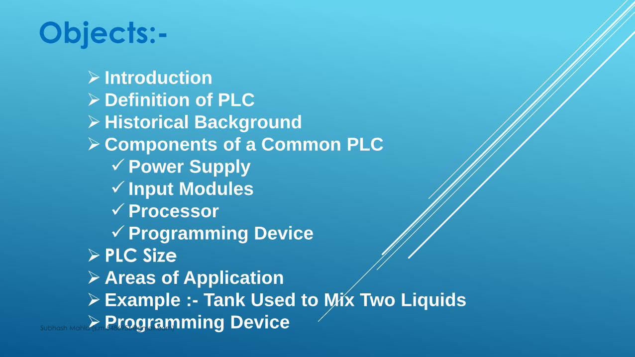
Objects:-
Introduction
Definition of PLC
Historical Background
Components of a Common PLC
Power Supply
Input Modules
Processor
Programming Device
PLC SizeAreas of Application
Example :- Tank Used to Mix Two Liquids
Programming DeviceSubhash Mahla ([email protected])
Introduction of PLC :-
This presentation introduces the basic hardware and
software components of a Programmable Controller
(PLC).
Programmable Logic Controllers are solid state devices
that can be programmed to performed
sequential and discrete state operation on external
equipment
They are designed to perform the logic functions
previously accomplished by electromechanical relays,
drum switches, mechanical and electronic timers and
counters, standalone digital PID controllers etc.Subhash Mahla ([email protected])
Programmable Logic Controllers :-
A digitally operating electronic apparatus which
uses a programming memory for the internal
storage of instructions for implementing specific
functions such as logic, sequencing, timing,
counting and arithmetic to control through digital
or analog modules, various types of machines or process.
Subhash Mahla ([email protected])

Historical Background :-
• The Hydramatic Division of the General Motors Corporation
specified the design criteria for the first programmable controller
in 1968
• To eliminate the high costs associated with inflexible, relay-controlled systems.
• The controller had to be designed in modular form, so that sub-
assemblies could be removed easily for replacement or repair.
• The control system needed the capability to pass data
collection to a central system.
• The method used to program the controller had to be simple, so
that it could be easily understood by plant personnel.Subhash Mahla ([email protected])
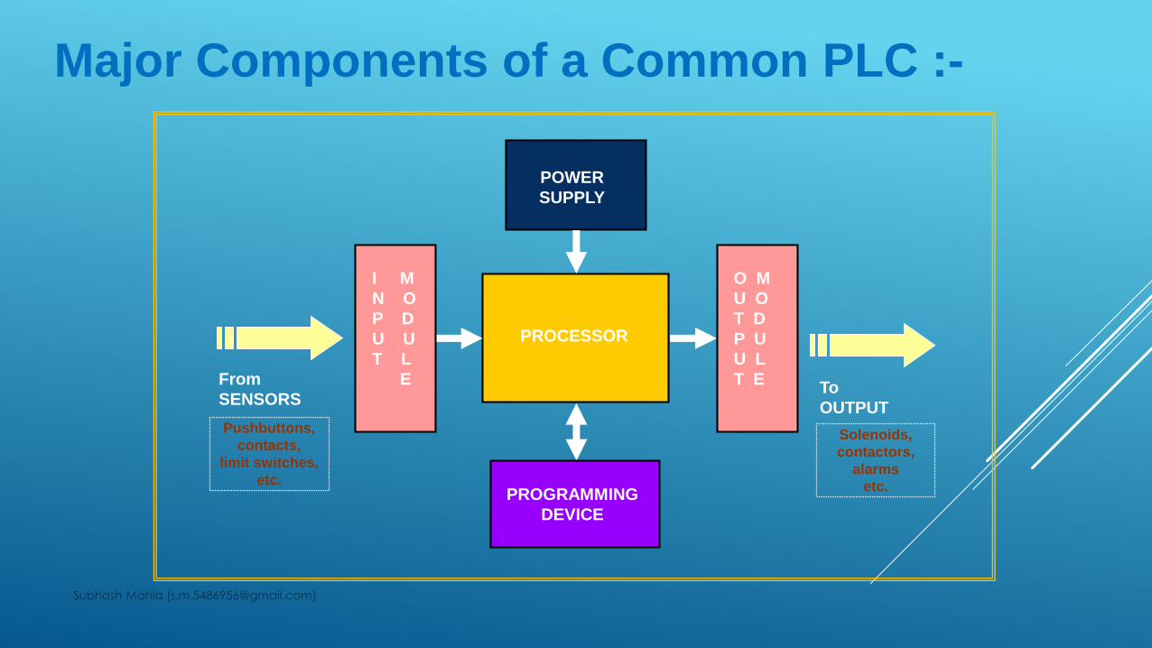
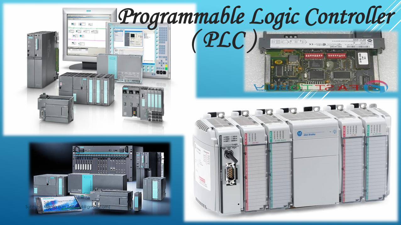
Major Components of a Common PLC :-
PROCESSOR
POWER
SUPPLY
I M
N O
P D
U U
T L
E
O M
U O
T D
P U
U L
T E
PROGRAMMING
DEVICE
From
SENSORS
Pushbuttons,
contacts,
limit switches,
etc.
To
OUTPUT
Solenoids,
contactors,
alarms
etc.
Subhash Mahla ([email protected])
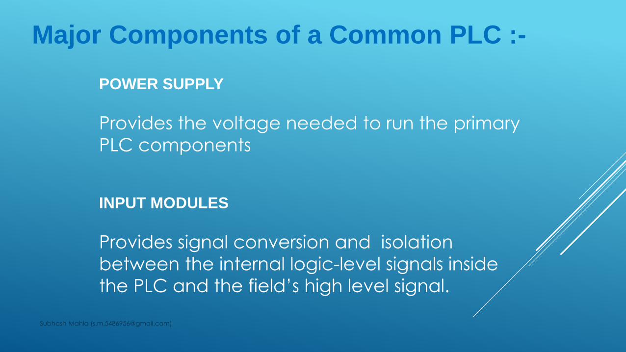
Major Components of a Common PLC :-
POWER SUPPLY
Provides the voltage needed to run the primary
PLC components
INPUT MODULES
Provides signal conversion and isolation
between the internal logic-level signals inside
the PLC and the field’s high level signal.
Subhash Mahla ([email protected])
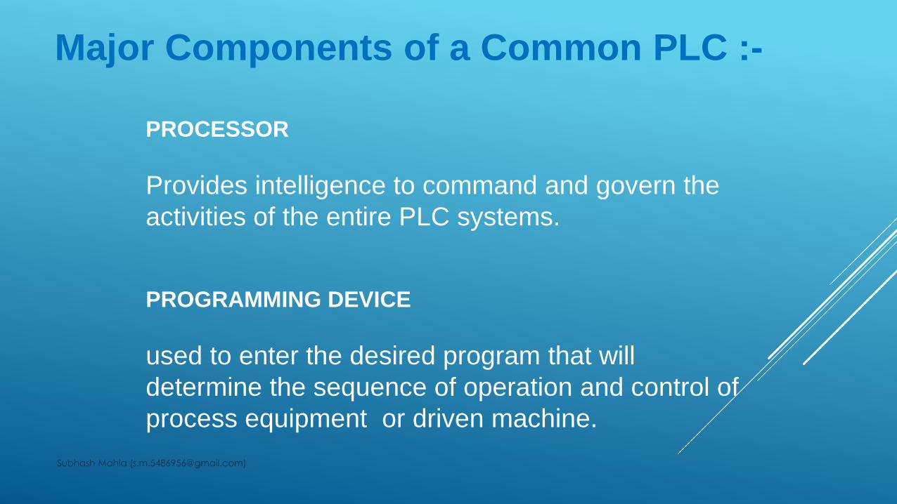
Major Components of a Common PLC :-
PROCESSOR
Provides intelligence to command and govern the
activities of the entire PLC systems.
PROGRAMMING DEVICE
used to enter the desired program that will
determine the sequence of operation and control of
process equipment or driven machine.
Subhash Mahla ([email protected])
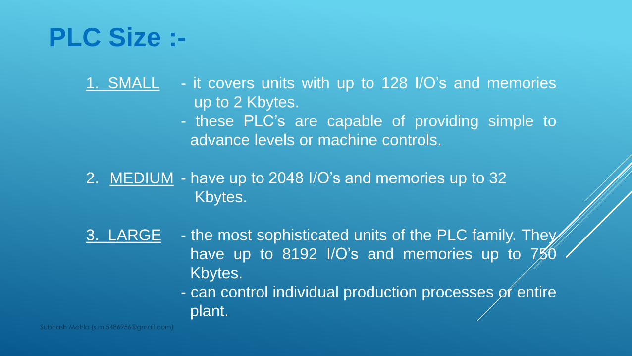
PLC Size :-
1. SMALL - it covers units with up to 128 I/O’s and memories
up to 2 Kbytes.
- these PLC’s are capable of providing simple to
advance levels or machine controls.
2. MEDIUM - have up to 2048 I/O’s and memories up to 32
Kbytes.
3. LARGE - the most sophisticated units of the PLC family. They
have up to 8192 I/O’s and memories up to 750
Kbytes.
- can control individual production processes or entire
plant.Subhash Mahla ([email protected])
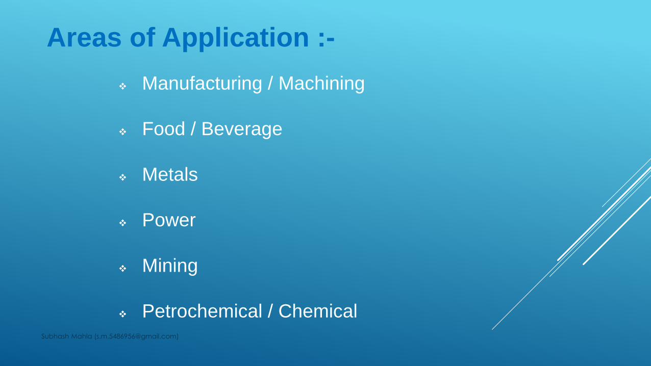
Areas of Application :-
Manufacturing / Machining
Food / Beverage
Metals
Power
Mining
Petrochemical / ChemicalSubhash Mahla ([email protected])
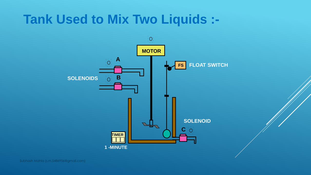
Tank Used to Mix Two Liquids :-
A
B
C
FS
MOTOR
TIMER
FLOAT SWITCH
SOLENOIDS
SOLENOID
1 -MINUTE
Subhash Mahla ([email protected])
Tank Used to Mix Two Liquids :-
A tank is used to mix two liquids. The control circuit operates as
follows:
1. When the start button is pressed, solenoids A and B
energize. This permits the two liquids to begin filling the tank.
2. When the tank is filled, the float switch trips. This de-
energizes solenoids A and B and starts the motor used to mix
the liquids together.
3. The motor is permitted to run for one minute. After one
minute has elapsed, the motor turns off and solenoid C
energizes to drain the tank.Subhash Mahla ([email protected])
4. When the tank is empty, the float switch de-energizes
solenoid C.
5. A stop button can be used to stop the process at any point.
6. If the motor becomes overloaded, the action of the entire
circuit will stop.
7. Once the circuit has been energized it will continue to operate
until it is manually stopped.
Tank Used to Mix Two Liquids :-
Subhash Mahla ([email protected])
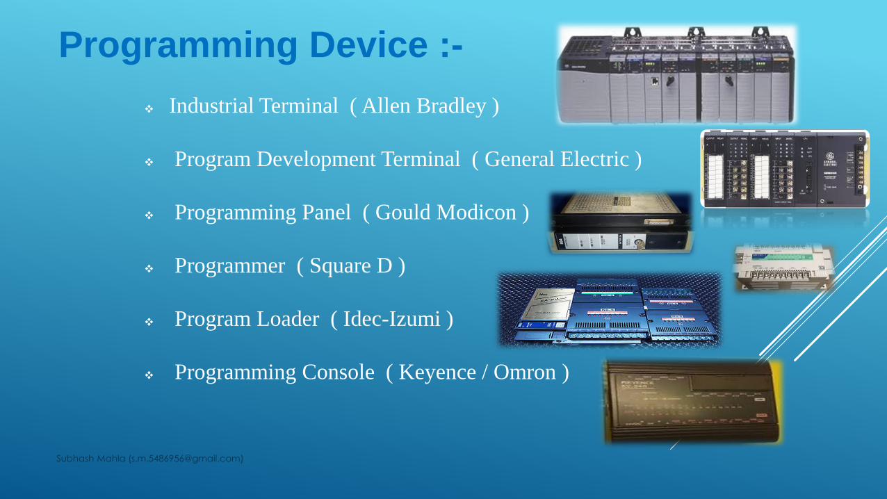
Programming Device :-
Industrial Terminal ( Allen Bradley )
Program Development Terminal ( General Electric )
Programming Panel ( Gould Modicon )
Programmer ( Square D )
Program Loader ( Idec-Izumi )
Programming Console ( Keyence / Omron )
Subhash Mahla ([email protected])
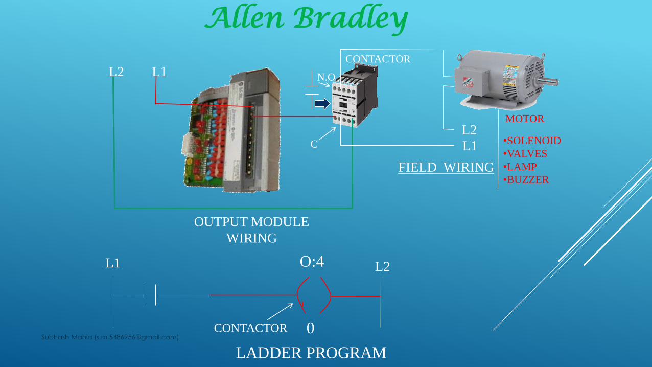
N.O
C
L2 L1
L1
L2
OUTPUT MODULE
WIRING
MOTOR
CONTACTOR
O:4
0CONTACTOR
LADDER PROGRAM
L1 L2
FIELD WIRING
•SOLENOID
•VALVES
•LAMP
•BUZZER
Allen Bradley
Subhash Mahla ([email protected])

Subhash Mahla ([email protected])

Subhash Mahla ([email protected])