Embed Size (px)
Citation preview
PROGRAMMABLE LOGIC CONTROLLER(PLC)
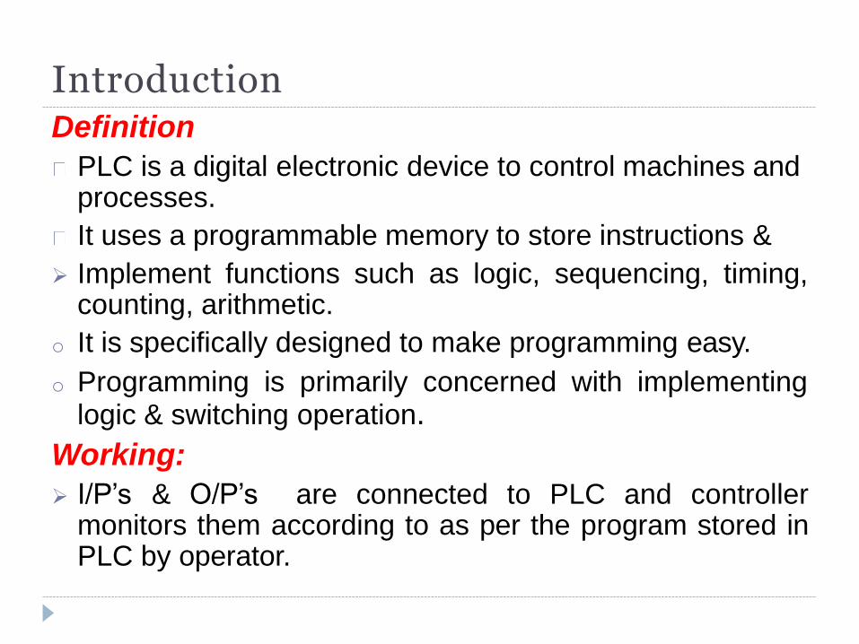
Introduction Definition
PLC is a digital electronic device to control machines and processes.
It uses a programmable memory to store instructions &
Implement functions such as logic, sequencing, timing, counting, arithmetic.
o It is specifically designed to make programming easy.
o Programming is primarily concerned with implementing logic & switching operation.
Working:
I/P’s & O/P’s are connected to PLC and controller monitors them according to as per the program stored in PLC by operator.
History: They are originally designed to replace hard wired relays &
timer logic control systems.
Advantages:
• Flexible
• Easy to use
• Easy to program.
• Much faster than relay operated system
Specific features of PLC:
• Rugged & designed to withstand vibration, temperature, humidity &
noise.
• Interfacing is inside the controller.
• They are easily programmed.
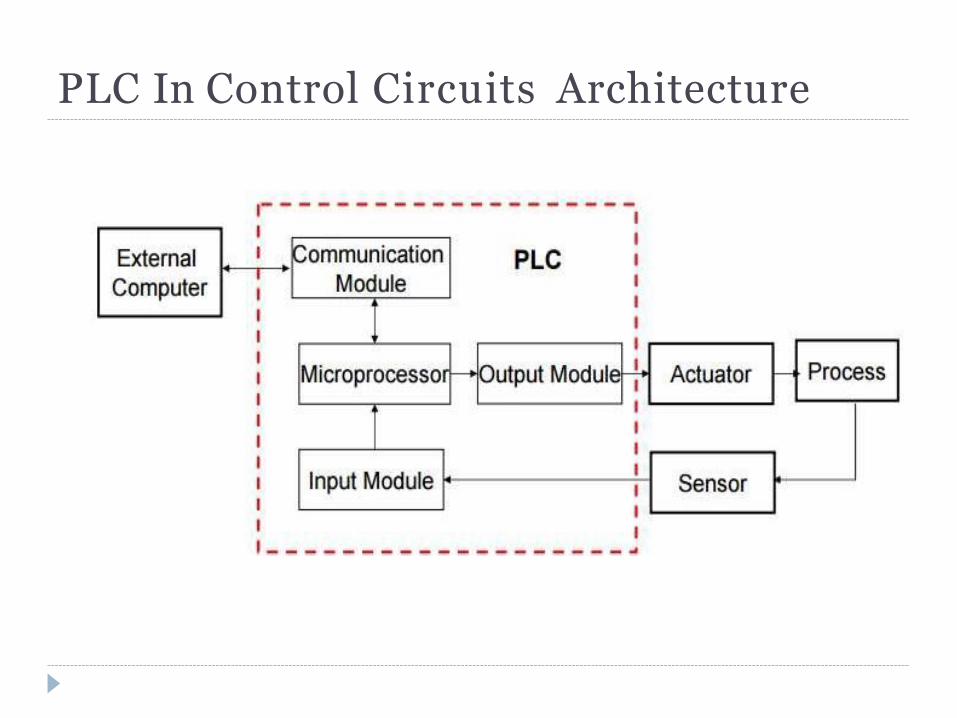
PLC In Control Circuits Architecture
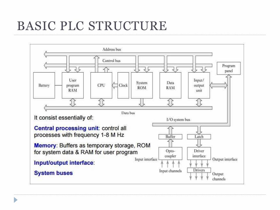
BASIC PLC STRUCTURE
Main components
CPU:
• Control & process all the information.
• Contain a clock with frequency between 1 & 8 MHz.
• It determine operating speed of PLC.
• Also provide timing & synchronization for all elements.
Memory: There are many types of memory in PLC, like:
• ROM
• RAM
• Temporary buffer stores for Input/Output channels.
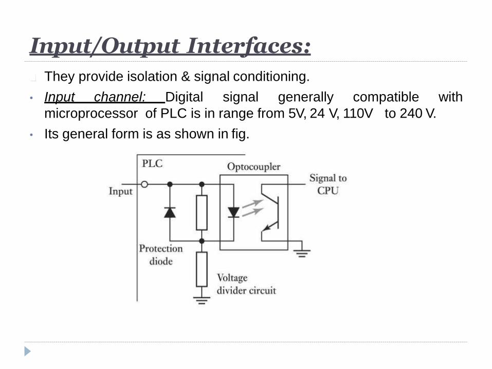
They provide isolation & signal conditioning.
with • Input channel: Digital signal generally compatible
microprocessor of PLC is in range from 5V, 24 V, 110V to 240 V.
• Its general form is as shown in fig.
Input/Output Interfaces:
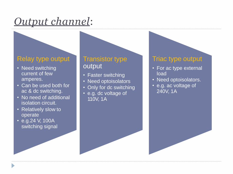
Relay type output
• Need switching current of few amperes.
• Can be used both for ac & dc switching.
• No need of additional isolation circuit.
• Relatively slow to operate
• e.g.24 V, 100A switching signal
Transistor type output
• Faster switching
• Need optoisolators
• Only for dc switching • e.g. dc voltage of
110V, 1A
Triac type output
• For ac type external load
• Need optoisolators. • e.g. ac voltage of
240V, 1A
Output channel:
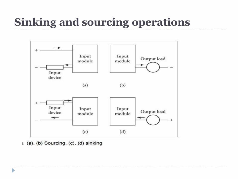
Sinking and sourcing operations
When choosing the type of input or output module for your PLC system it
is very important to have a solid understanding of sinking and sourcing
concepts.
Only applicable to dc load
It refer to electrical configurations of the circuit in the module & field input
devices.
When a device provides current when it is ON it is said to be sourcing
current.
When a device receives current when it is ON it is said to be sinking
current.
There are both sinking & sourcing field devices as well as sinking &
sourcing input module.
But it’s a common practice to use input module in sinking current
mode.
Sinking and sourcing operations
Inputting Programs
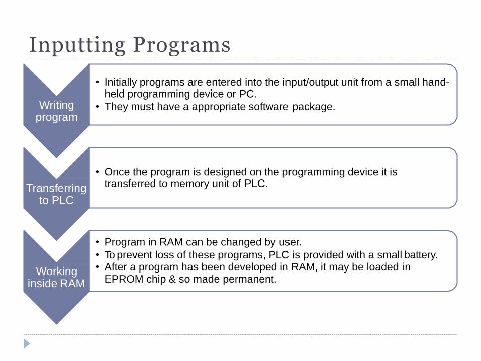
Writing program
• Initially programs are entered into the input/output unit from a small hand- held programming device or PC.
• They must have a appropriate software package.
Transferring to PLC
• Once the program is designed on the programming device it is transferred to memory unit of PLC.
Working inside RAM
• Program in RAM can be changed by user.
• To prevent loss of these programs, PLC is provided with a small battery. • After a program has been developed in RAM, it may be loaded in
EPROM chip & so made permanent.
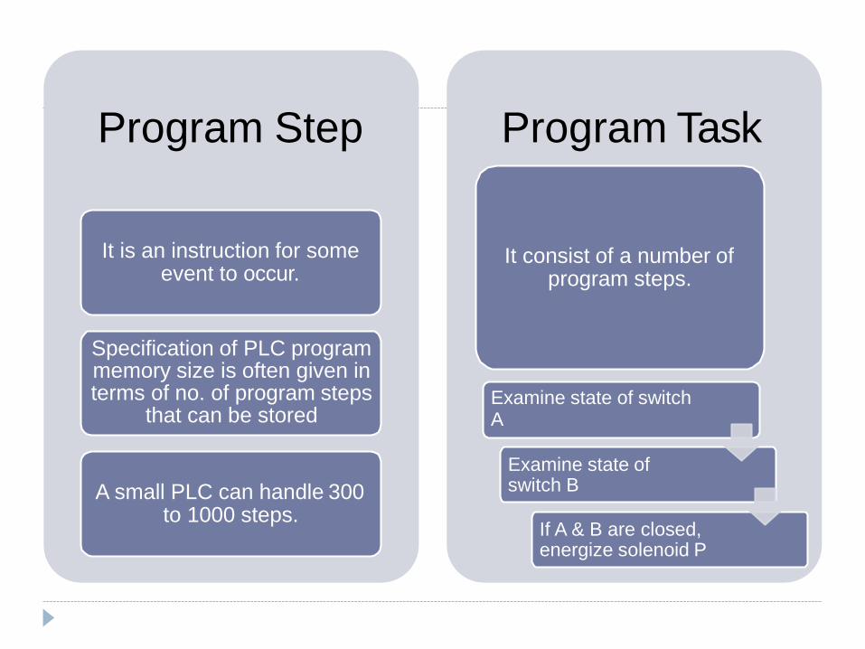
Program Step
It is an instruction for some event to occur.
Specification of PLC program memory size is often given in terms of no. of program steps
that can be stored
A small PLC can handle 300 to 1000 steps.
Program Task
It consist of a number of program steps.
Examine state of switch A
Examine state of switch B
If A & B are closed, energize solenoid P
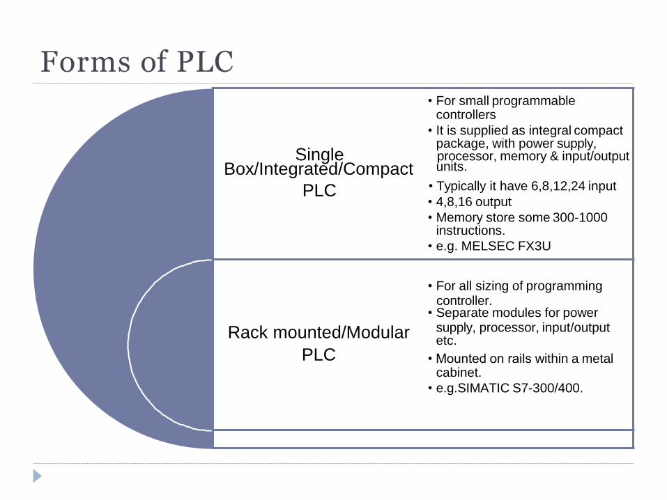
Forms of PLC • For small programmable
controllers
• It is supplied as integral compact package, with power supply,
Single processor, memory & input/output Box/Integrated/Compact units.
PLC • Typically it have 6,8,12,24 input
• 4,8,16 output
• Memory store some 300-1000 instructions.
• e.g. MELSEC FX3U
• For all sizing of programming
controller. • Separate modules for power
Rack mounted/Modular supply, processor, input/output etc.
PLC • Mounted on rails within a metal cabinet.
• e.g.SIMATIC S7-300/400.
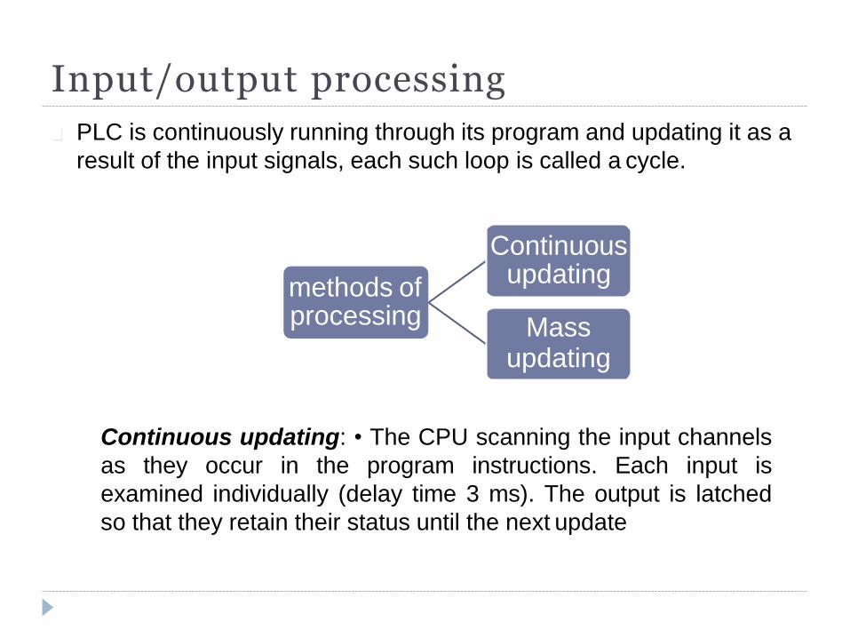
Input/output processing
PLC is continuously running through its program and updating it as a
result of the input signals, each such loop is called a cycle.
methods of processing
Continuous updating
Mass updating
Continuous updating: • The CPU scanning the input channels
as they occur in the program instructions. Each input is
examined individually (delay time 3 ms). The output is latched
so that they retain their status until the next update
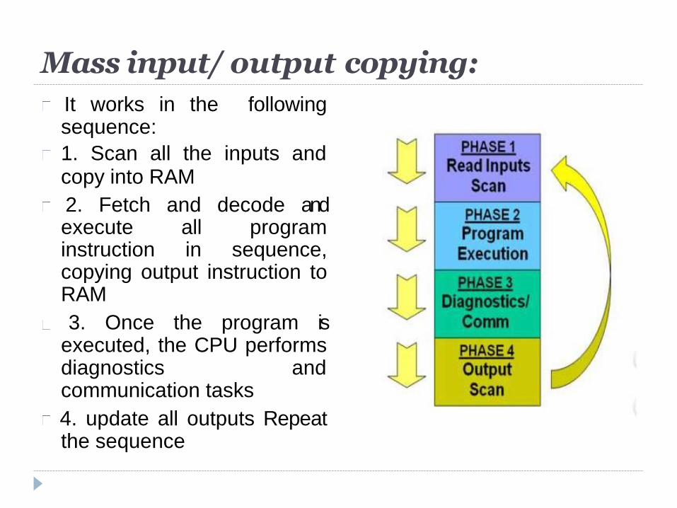
Mass input/ output copying:
It works in the following sequence:
1. Scan all the inputs and copy into RAM
2. Fetch and decode and execute all program instruction in sequence, copying output instruction to RAM
3. Once the program is executed, the CPU performs diagnostics and communication tasks
4. update all outputs Repeat the sequence
Input/ Output address
The inputs and outputs are identified by their addresses.
the notation used depends on the PLC manufacturer.
For small PLC, it is just a number preceded by a letter to indicate
whether it is an input or an output
With large PLCs having several racks of input and output channels
and a number of modules in each rack, the rack and modules are
numbered and so an input or output is identified by its rack number
followed by the number of the module in that rack and then a
number to show its terminal in the module.
E.g.The Allen-Bradley PLC-5 has I: 012/03 to indicate an input in rack
01 at module 2 and terminal 03
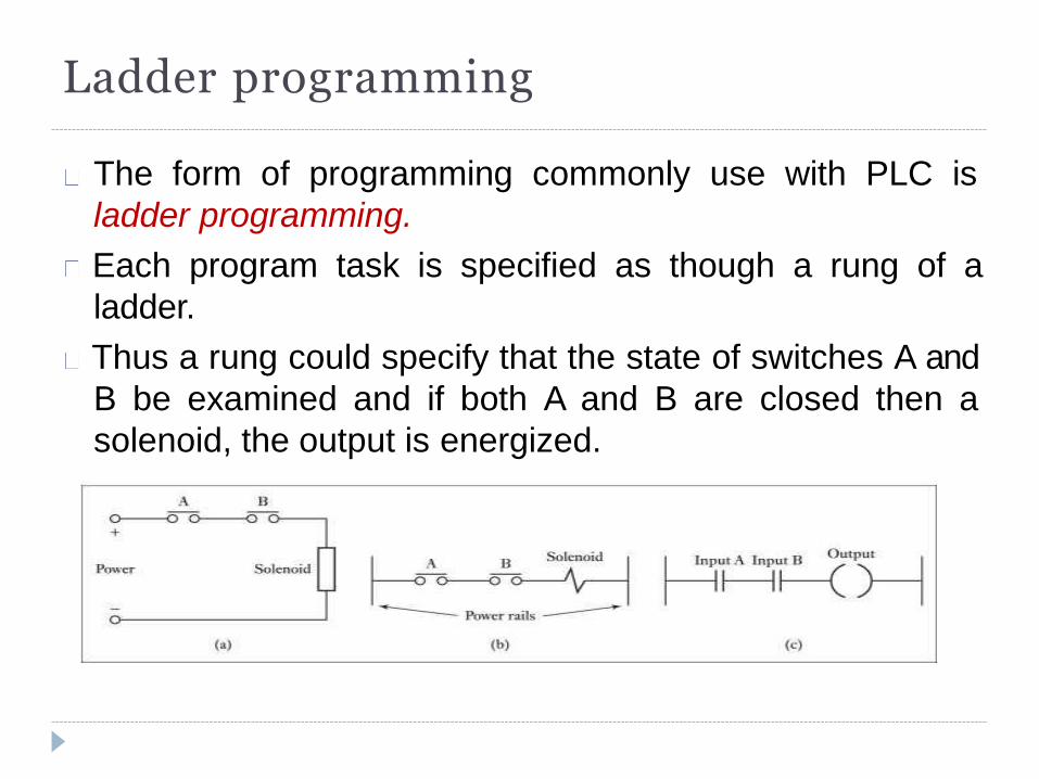
Ladder programming
The form of programming commonly use with PLC is
ladder programming.
Each program task is specified as though a rung of a
ladder.
Thus a rung could specify that the state of switches A and
B be examined and if both A and B are closed then a
solenoid, the output is energized.
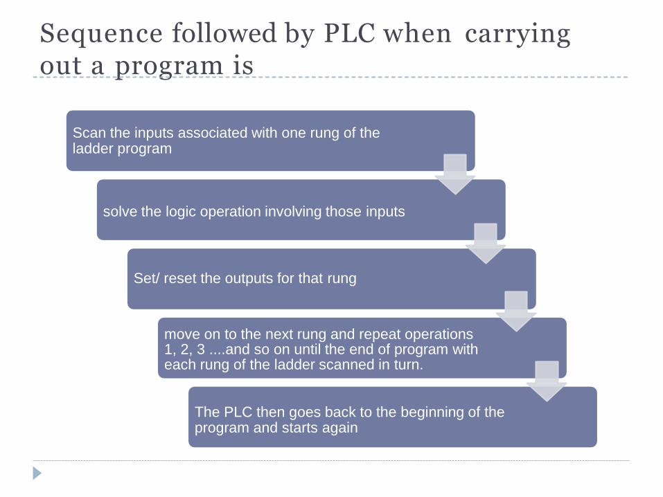
Sequence followed by PLC when carrying out a program is
Scan the inputs associated with one rung of the ladder program
solve the logic operation involving those inputs
Set/ reset the outputs for that rung
move on to the next rung and repeat operations 1, 2, 3 ....and so on until the end of program with each rung of the ladder scanned in turn.
The PLC then goes back to the beginning of the program and starts again
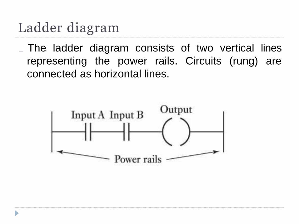
Ladder diagram
The ladder diagram consists of two vertical lines
representing the power rails. Circuits (rung) are
connected as horizontal lines.
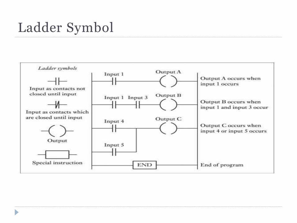
Ladder Symbol
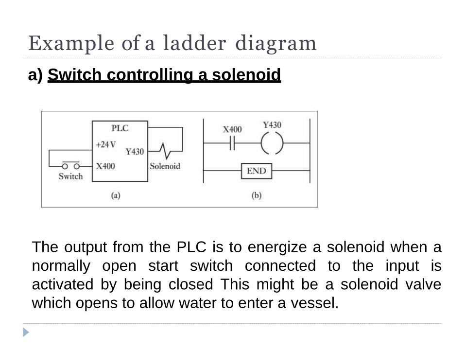
Example of a ladder diagram
a) Switch controlling a solenoid
The output from the PLC is to energize a solenoid when a
normally open start switch connected to the input is
activated by being closed This might be a solenoid valve
which opens to allow water to enter a vessel.
Example of a ladder diagram
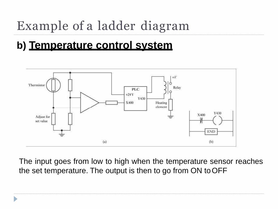
b) Temperature control system
The input goes from low to high when the temperature sensor reaches
the set temperature. The output is then to go from ON to OFF
Logic Functions
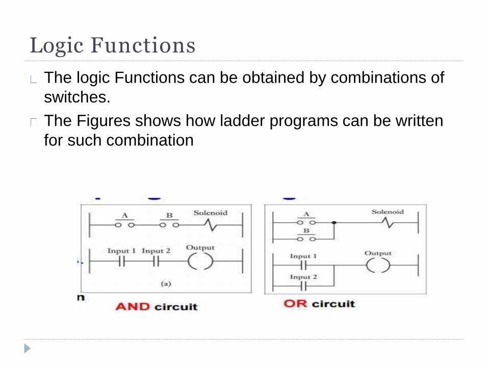
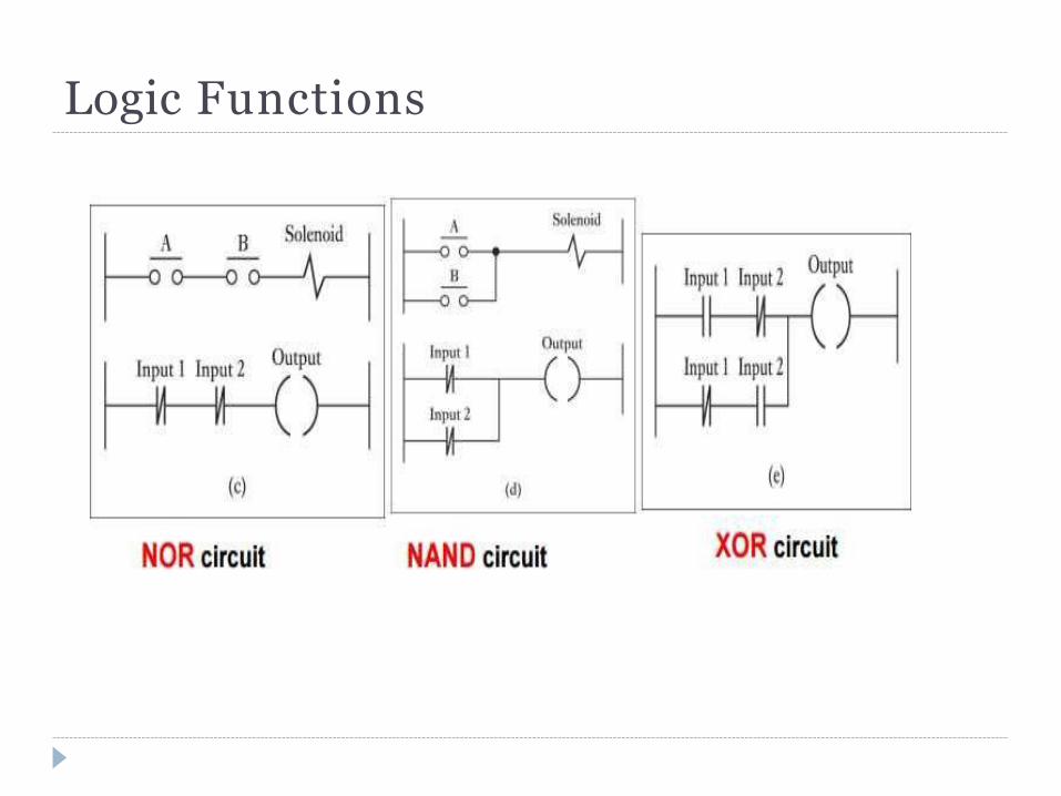
The logic Functions can be obtained by combinations of
switches.
The Figures shows how ladder programs can be written
for such combination
Logic Functions
Example A B C OUTPUT
0 0 0 0
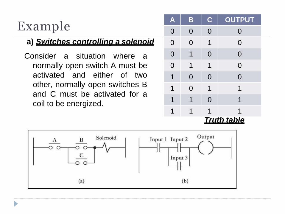
a) Switches controlling a solenoid
Consider a situation where a
normally open switch A must be
activated and either of two
other, normally open switches B
and C must be activated for a
coil to be energized.
0 0 1 0
0 1 0 0
0 1 1 0
1 0 0 0
1 0 1 1
1 1 0 1
1 1 1 1
Truth table
Example
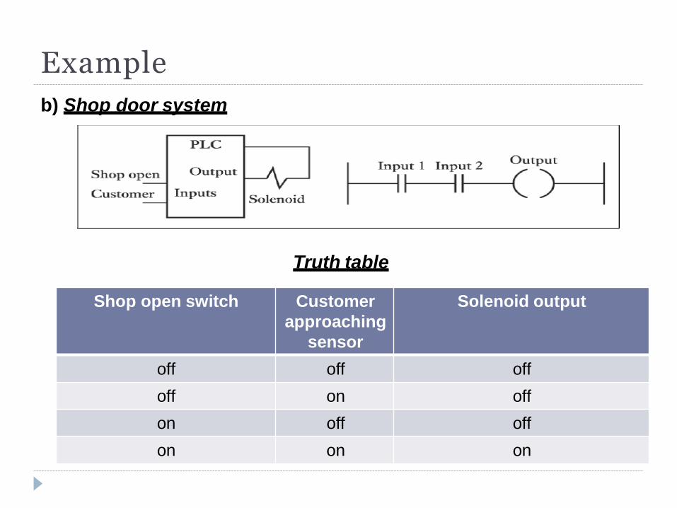
b) Shop door system
Truth table
Shop open switch Customer
approaching
sensor
Solenoid output
off off off
off on off
on off off
on on on
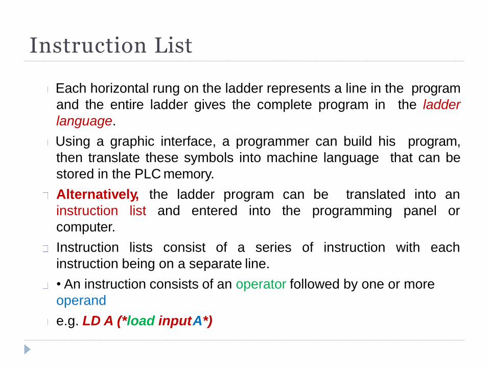
Instruction List
Each horizontal rung on the ladder represents a line in the program
and the entire ladder gives the complete program in the ladder
language.
Using a graphic interface, a programmer can build his program,
then translate these symbols into machine language that can be
stored in the PLC memory.
Alternatively, the ladder program can be translated into an
list and entered into the programming panel or instruction
computer.
Instruction lists consist of a series of instruction with each
instruction being on a separate line.
• An instruction consists of an operator followed by one or more
operand
e.g. LD A (*load input A*)
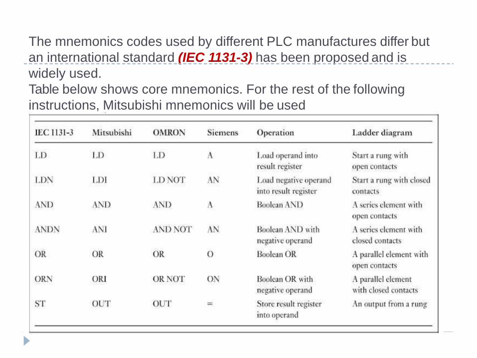
The mnemonics codes used by different PLC manufactures differ but
an international standard (IEC 1131-3) has been proposed and is
widely used.
Table below shows core mnemonics. For the rest of the following
instructions, Mitsubishi mnemonics will be used
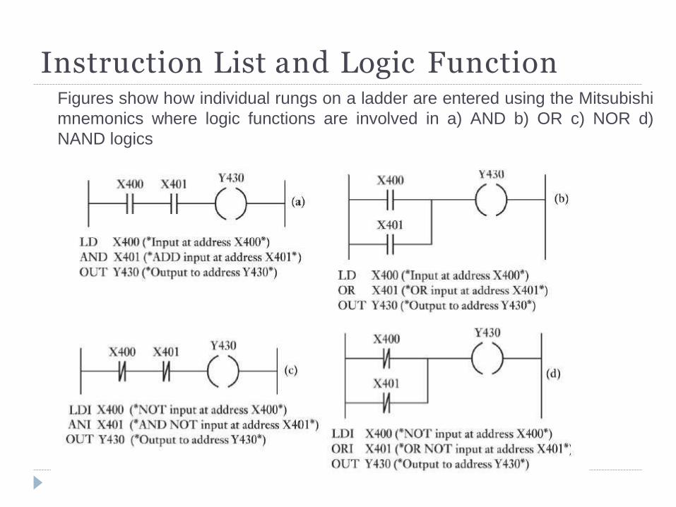
Instruction List and Logic Function Figures show how individual rungs on a ladder are entered using the Mitsubishi
mnemonics where logic functions are involved in a) AND b) OR c) NOR d)
NAND logics
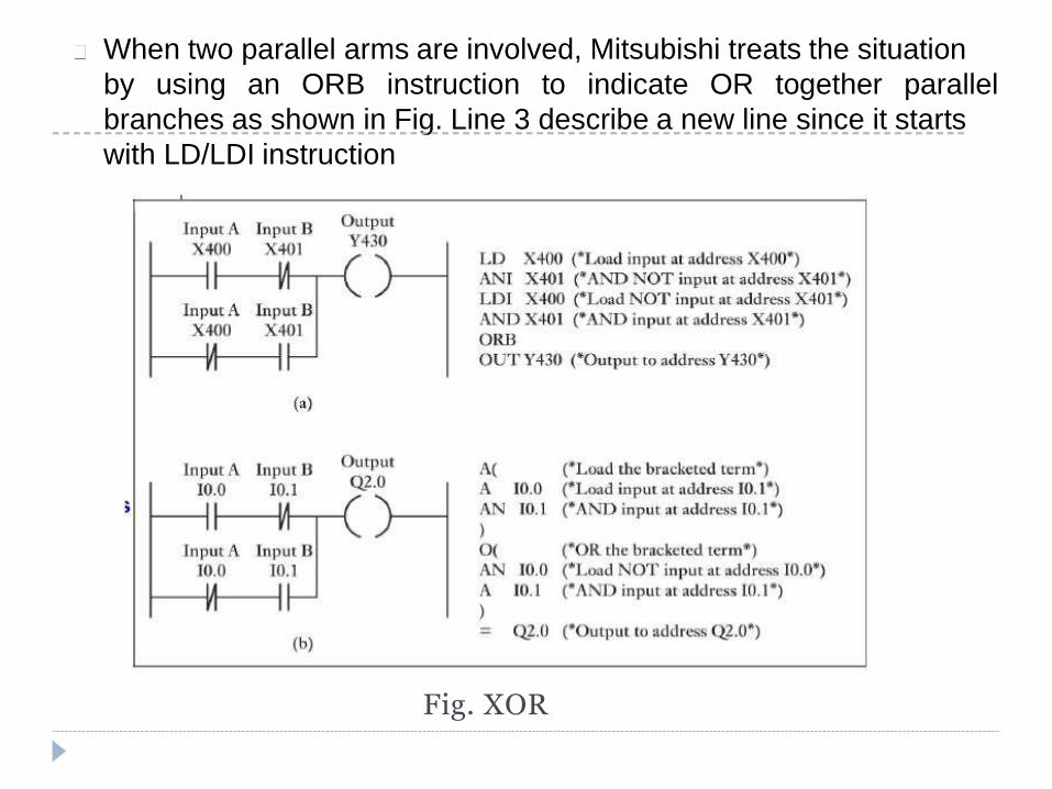
When two parallel arms are involved, Mitsubishi treats the situation
by using an ORB instruction to indicate OR together parallel
branches as shown in Fig. Line 3 describe a new line since it starts
with LD/LDI instruction
Fig. XOR
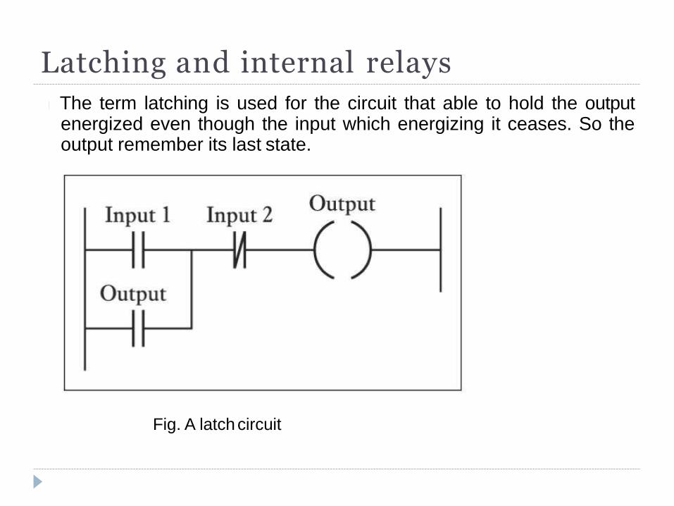
The term latching is used for the circuit that able to hold the output energized even though the input which energizing it ceases. So the output remember its last state.
Latching and internal relays
Fig. A latch circuit
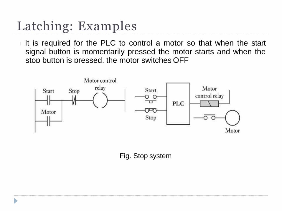
Latching: Examples
It is required for the PLC to control a motor so that when the start signal button is momentarily pressed the motor starts and when the stop button is pressed, the motor switches OFF
Fig. Stop system
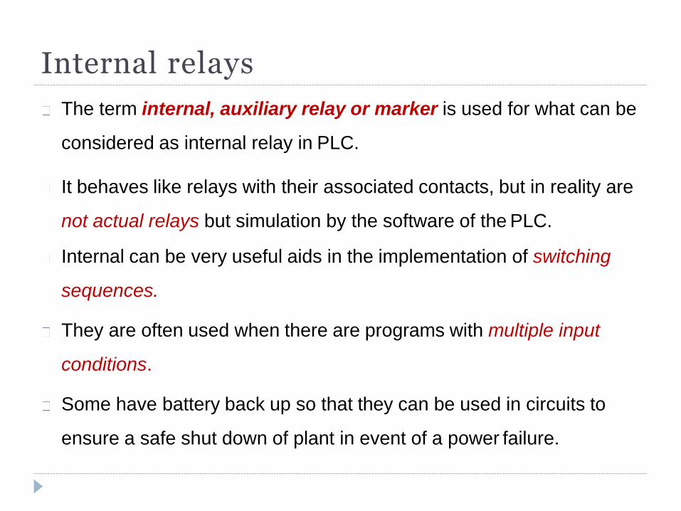
Internal relays
The term internal, auxiliary relay or marker is used for what can be
considered as internal relay in PLC.
It behaves like relays with their associated contacts, but in reality are
not actual relays but simulation by the software of the PLC.
Internal can be very useful aids in the implementation of switching
sequences.
They are often used when there are programs with multiple input
conditions.
Some have battery back up so that they can be used in circuits to
ensure a safe shut down of plant in event of a power failure.
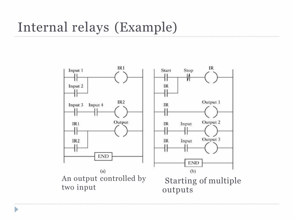
An output controlled by two input
Starting of multiple outputs
Internal relays (Example)
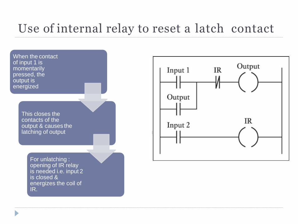
Use of internal relay to reset a latch contact
When the contact of input 1 is momentarily pressed, the output is energized
This closes the contacts of the output & causes the latching of output
For unlatching : opening of IR relay is needed i.e. input 2 is closed & energizes the coil of IR.
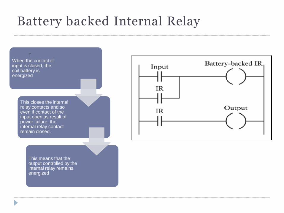
Battery backed Internal Relay
, When the contact of input is closed, the coil battery is energized
This closes the internal relay contacts and so even if contact of the input open as result of power failure, the internal relay contact remain closed.
This means that the output controlled by the internal relay remains energized
Timers
In many control tasks there is a need to control time. For example, a
motor or a pump might need to be controlled to operate for a particular
interval of time, or perhaps be switched on after some time interval.
PLCs thus have timers as built-in devices.
Timers count fractions of seconds or seconds using the internal CPU
clock. considered.
A common approach is to consider timers to behave like relays with coils
which when energized result in the closure or opening of contacts after
some preset time.
The timer is thus treated as an output for a rung with control being
exercised over pairs of contacts elsewhere
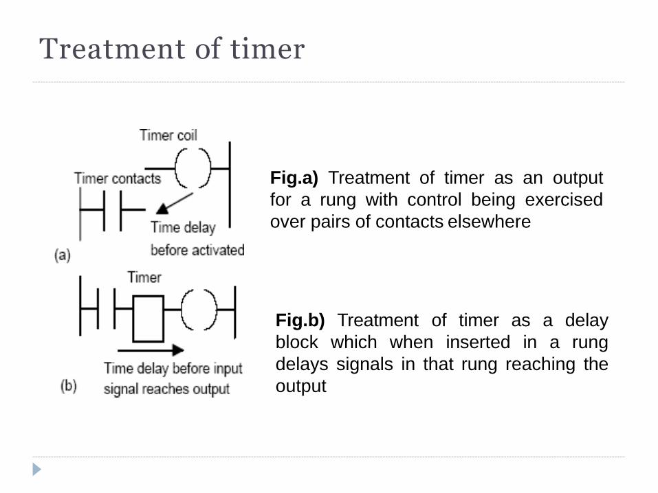
Treatment of timer
Fig.a) Treatment of timer as an output
for a rung with control being exercised
over pairs of contacts elsewhere
Fig.b) Treatment of timer as a delay
block which when inserted in a rung
delays signals in that rung reaching the
output
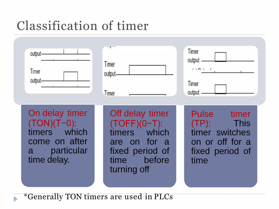
Classification of timer
On delay timer (TON)(T−0): timers which come on after a particular time delay.
Off delay timer (TOFF)(0−T): timers which are on for a fixed period of time before
Pulse timer (TP): This timer switches on or off for a fixed period of time
turning off
*Generally TON timers are used in PLCs
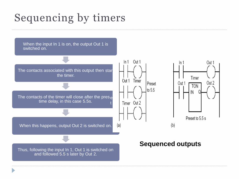
Sequencing by timers
Sequenced outputs
When the input In 1 is on, the output Out 1 is switched on.
The contacts associated with this output then the timer.
start
e
t
The contacts of the timer will close after the pres time delay, in this case 5.5s.
When this happens, output Out 2 is switched on.
Thus, following the input In 1, Out 1 is switched on and followed 5.5 s later by Out 2.
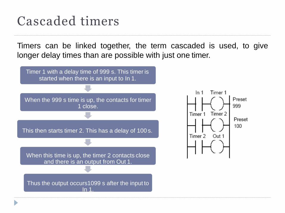
Cascaded timers
Timers can be linked together, the term cascaded is used, to give
longer delay times than are possible with just one timer.
Timer 1 with a delay time of 999 s. This timer is started when there is an input to In 1.
When the 999 s time is up, the contacts for timer 1 close.
This then starts timer 2. This has a delay of 100 s.
When this time is up, the timer 2 contacts close
and there is an output from Out 1.
Thus the output occurs1099 s after the input to In 1.
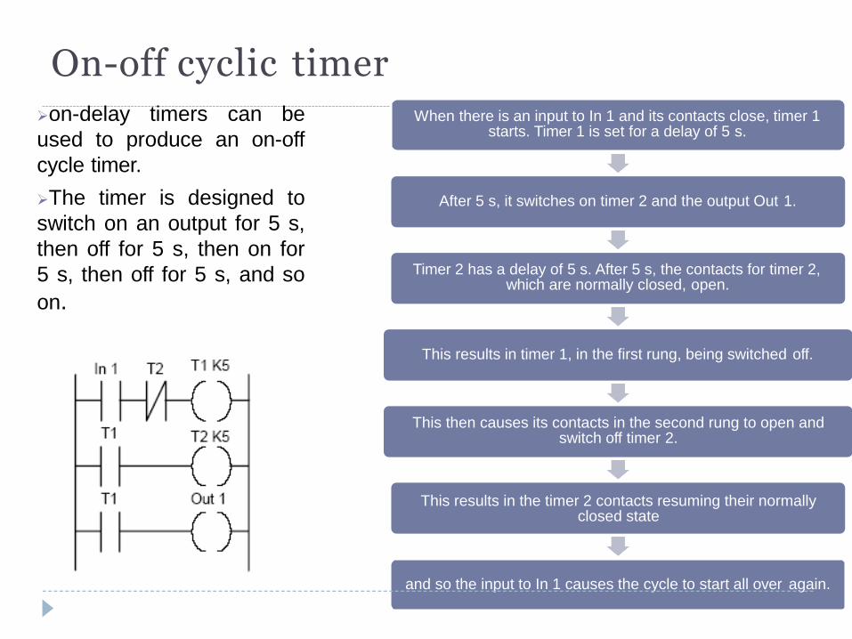
On-off cyclic timer on-delay timers can be
used to produce an on-off
cycle timer.
The timer is designed to
switch on an output for 5 s,
then off for 5 s, then on for
5 s, then off for 5 s, and so
on.
When there is an input to In 1 and its contacts close, timer 1 starts. Timer 1 is set for a delay of 5 s.
After 5 s, it switches on timer 2 and the output Out 1.
Timer 2 has a delay of 5 s. After 5 s, the contacts for timer 2, which are normally closed, open.
This results in timer 1, in the first rung, being switched off.
This then causes its contacts in the second rung to open and switch off timer 2.
This results in the timer 2 contacts resuming their normally
closed state
and so the input to In 1 causes the cycle to start all over again.
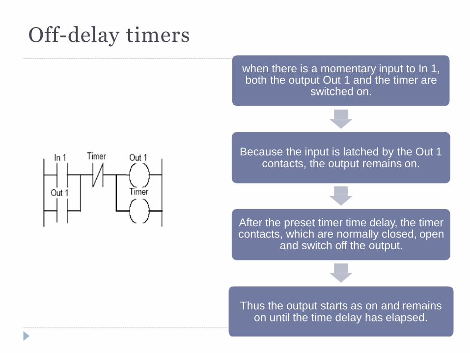
Off-delay timers
when there is a momentary input to In 1, both the output Out 1 and the timer are
switched on.
Because the input is latched by the Out 1 contacts, the output remains on.
After the preset timer time delay, the timer contacts, which are normally closed, open
and switch off the output.
Thus the output starts as on and remains on until the time delay has elapsed.
Counters
Counters are provided as built-in elements in PLCs and allow the
number of occurrences of input signals to be counted.
This might be where items have to be counted as they pass along a
conveyor belt, or the number of revolutions of a shaft, or perhaps the
number of people passing through a door.
Forms of counter:
o down-counters: Down-counters countdown from the preset value to zero,
i.e. events are subtracted from the set value. When the counter reaches the
zero value, its contacts change state
o up-counters: Up-counters count from zero up to the preset value, i.e.
events are added until the number reaches the preset value.
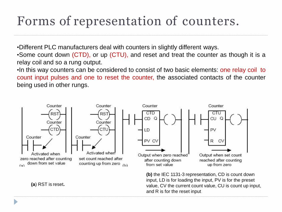
Forms of representation of counters.
(a) RST is reset.
(b) the IEC 1131-3 representation, CD is count down
input, LD is for loading the input, PV is for the preset
value, CV the current count value, CU is count up input,
and R is for the reset input.
•Different PLC manufacturers deal with counters in slightly different ways.
•Some count down (CTD), or up (CTU), and reset and treat the counter as though it is a
relay coil and so a rung output.
•In this way counters can be considered to consist of two basic elements: one relay coil to
count input pulses and one to reset the counter, the associated contacts of the counter
being used in other rungs.
Basic counter programming
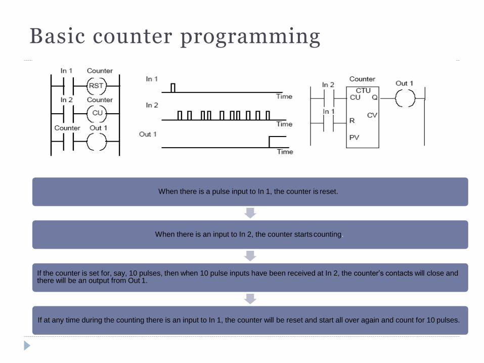
When there is a pulse input to In 1, the counter is reset.
When there is an input to In 2, the counter starts counting.
If the counter is set for, say, 10 pulses, then when 10 pulse inputs have been received at In 2, the counter’s contacts will close and there will be an output from Out 1.
If at any time during the counting there is an input to In 1, the counter will be reset and start all over again and count for 10 pulses.
Example
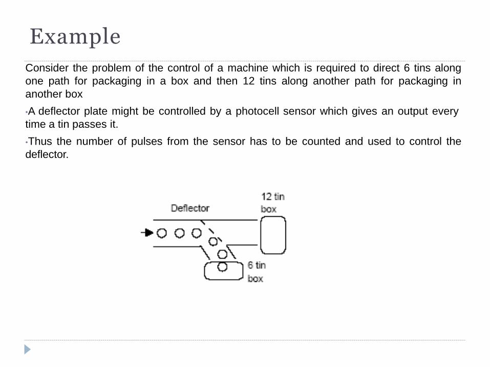
Consider the problem of the control of a machine which is required to direct 6 tins along
one path for packaging in a box and then 12 tins along another path for packaging in
another box
•A deflector plate might be controlled by a photocell sensor which gives an output every
time a tin passes it.
•Thus the number of pulses from the sensor has to be counted and used to control the
deflector.
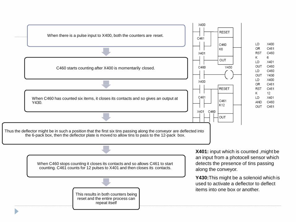
When there is a pulse input to X400, both the counters are reset.
C460 starts counting after X400 is momentarily closed.
When C460 has counted six items, it closes its contacts and so gives an output at Y430.
Thus the deflector might be in such a position that the first six tins passing along the conveyor are deflected into the 6-pack box, then the deflector plate is moved to allow tins to pass to the 12-pack box.
When C460 stops counting it closes its contacts and so allows C461 to start counting. C461 counts for 12 pulses to X401 and then closes its contacts.
This results in both counters being reset and the entire process can
repeat itself
X401: input which is counted ,might be
an input from a photocell sensor which
detects the presence of tins passing
along the conveyor.
Y430:This might be a solenoid which is
used to activate a deflector to deflect
items into one box or another.
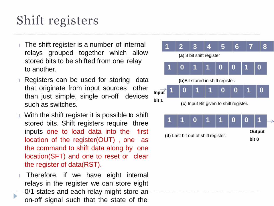
Shift registers
The shift register is a number of internal
relays grouped together which allow
stored bits to be shifted from one relay
to another.
Registers can be used for storing data
that originate from input sources other
than just simple, single on-off devices
such as switches.
With the shift register it is possible to shift
stored bits. Shift registers require three
inputs one to load data into the first
location of the register(OUT) , one as
the command to shift data along by one
location(SFT) and one to reset or clear
the register of data(RST).
Therefore, if we have eight internal
relays in the register we can store eight
0/1 states and each relay might store an
on-off signal such that the state of the
1 2 3 4 5 6 7 8
1 0 1 1 0 0 1 0
(a) 8 bit shift register
(b)Bit stored in shift register.
1 0 1 1 0 0 1 0
(c) Input Bit given to shift register.
Input
bit 1
Output
bit 0
1 1 0 1 1 0 0 1
(d) Last bit out of shift register.
Shift registers
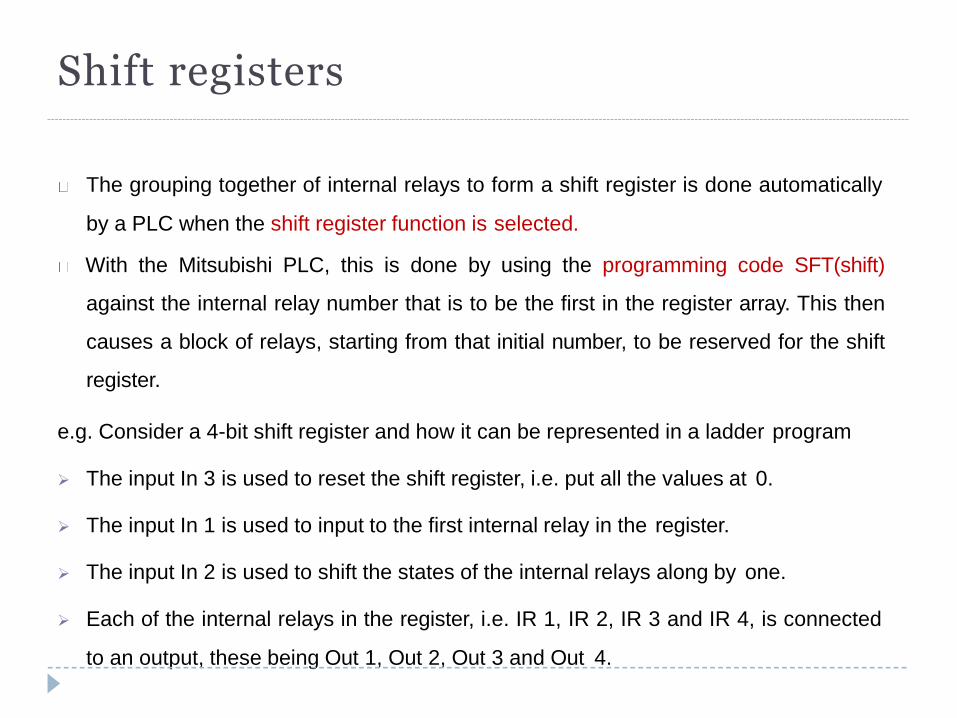
The grouping together of internal relays to form a shift register is done automatically
by a PLC when the shift register function is selected.
With the Mitsubishi PLC, this is done by using the programming code SFT(shift)
against the internal relay number that is to be the first in the register array. This then
causes a block of relays, starting from that initial number, to be reserved for the shift
register.
e.g. Consider a 4-bit shift register and how it can be represented in a ladder program
The input In 3 is used to reset the shift register, i.e. put all the values at 0.
The input In 1 is used to input to the first internal relay in the register.
The input In 2 is used to shift the states of the internal relays along by one.
Each of the internal relays in the register, i.e. IR 1, IR 2, IR 3 and IR 4, is connected
to an output, these being Out 1, Out 2, Out 3 and Out 4.
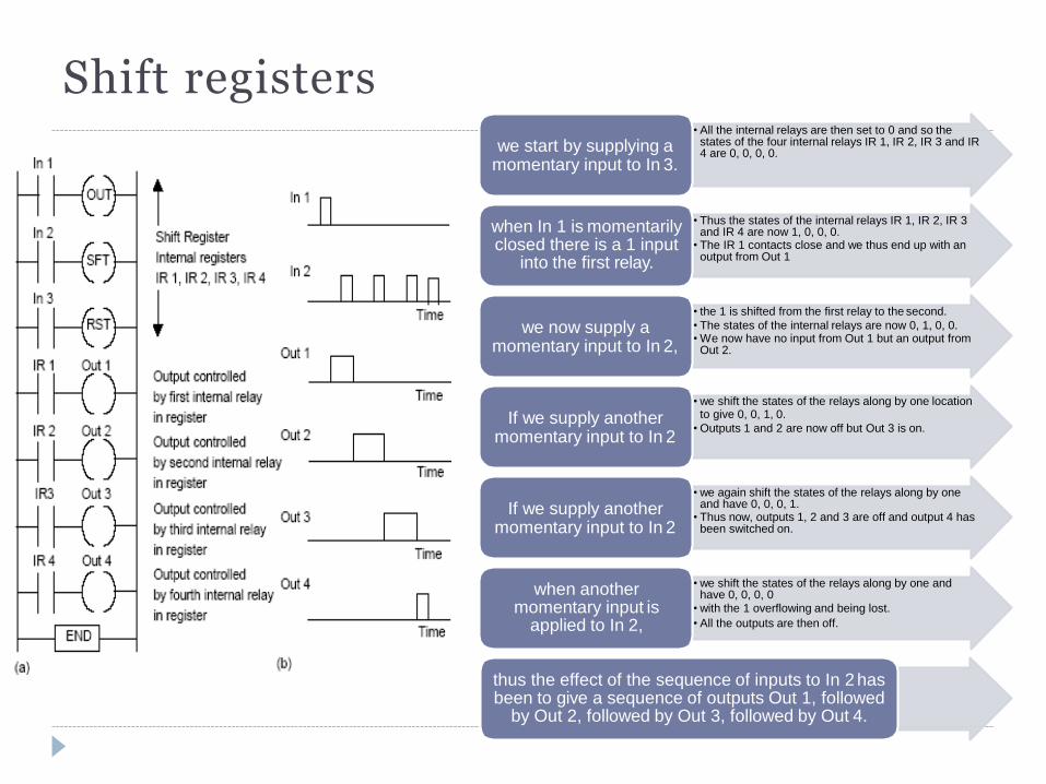
Shift registers • All the internal relays are then set to 0 and so the
states of the four internal relays IR 1, IR 2, IR 3 and IR 4 are 0, 0, 0, 0.
we start by supplying a momentary input to In 3.
• Thus the states of the internal relays IR 1, IR 2, IR 3 and IR 4 are now 1, 0, 0, 0.
• The IR 1 contacts close and we thus end up with an output from Out 1
when In 1 is momentarily closed there is a 1 input
into the first relay.
• the 1 is shifted from the first relay to the second.
• The states of the internal relays are now 0, 1, 0, 0. • We now have no input from Out 1 but an output from
Out 2.
we now supply a momentary input to In 2,
• we shift the states of the relays along by one location to give 0, 0, 1, 0.
• Outputs 1 and 2 are now off but Out 3 is on. If we supply another
momentary input to In 2
• we again shift the states of the relays along by one and have 0, 0, 0, 1.
• Thus now, outputs 1, 2 and 3 are off and output 4 has been switched on.
If we supply another momentary input to In 2
• we shift the states of the relays along by one and have 0, 0, 0, 0
• with the 1 overflowing and being lost.
• All the outputs are then off.
when another momentary input is
applied to In 2,
thus the effect of the sequence of inputs to In 2 has been to give a sequence of outputs Out 1, followed
by Out 2, followed by Out 3, followed by Out 4.
Master control relay
When large numbers of outputs have to be controlled, it is sometimes
necessary for whole sections of ladder diagrams to be turned on or off when
certain criteria are realized. This could be achieved by including the contacts
of the same internal relay in each of the rungs so that its operation affects all
of them.
An alternative is to use a master control relay.
To program an internal relay M100 to act as master control relay contacts the
program instruction is: MC M100
To program the resetting of that relay, the program instruction is: MCR M100
Master control relay
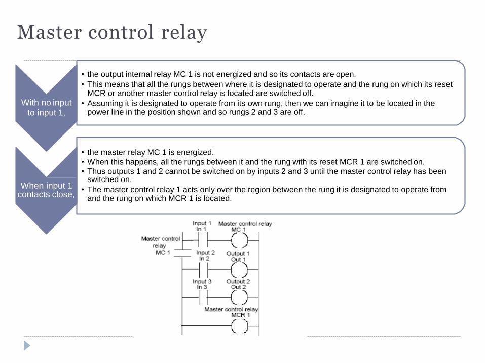
With no input to input 1,
• the output internal relay MC 1 is not energized and so its contacts are open.
• This means that all the rungs between where it is designated to operate and the rung on which its reset MCR or another master control relay is located are switched off.
• Assuming it is designated to operate from its own rung, then we can imagine it to be located in the power line in the position shown and so rungs 2 and 3 are off.
When input 1 contacts close,
• the master relay MC 1 is energized.
• When this happens, all the rungs between it and the rung with its reset MCR 1 are switched on. • Thus outputs 1 and 2 cannot be switched on by inputs 2 and 3 until the master control relay has been
switched on.
• The master control relay 1 acts only over the region between the rung it is designated to operate from and the rung on which MCR 1 is located.
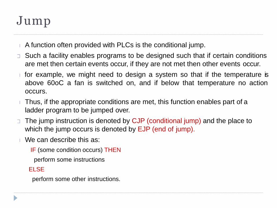
Jump
A function often provided with PLCs is the conditional jump.
Such a facility enables programs to be designed such that if certain conditions
are met then certain events occur, if they are not met then other events occur.
for example, we might need to design a system so that if the temperature is
above 60oC a fan is switched on, and if below that temperature no action
occurs.
Thus, if the appropriate conditions are met, this function enables part of a
ladder program to be jumped over.
The jump instruction is denoted by CJP (conditional jump) and the place to
which the jump occurs is denoted by EJP (end of jump).
We can describe this as:
IF (some condition occurs) THEN
perform some instructions
ELSE
perform some other instructions.
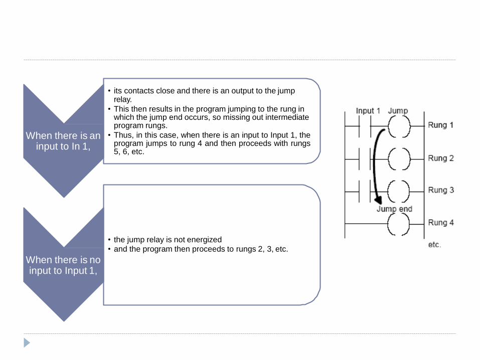
When there is an input to In 1,
• its contacts close and there is an output to the jump relay.
• This then results in the program jumping to the rung in which the jump end occurs, so missing out intermediate program rungs.
• Thus, in this case, when there is an input to Input 1, the program jumps to rung 4 and then proceeds with rungs 5, 6, etc.
• the jump relay is not energized • and the program then proceeds to rungs 2, 3, etc.
When there is no input to Input 1,
Data Handling
The operations that may be carried out with a PLC on data words include:
Moving data
Comparison of magnitude of data
Arithmetic operations
Conversion between number system
Data instructions require memory addresses, so data registers are used to stored binary words (8 or 16 bits) and is given an address such as D0, D1, D2…
Each instruction has to specify the form of the operation, the source of the data used in terms of its data register and the destination data register of the data
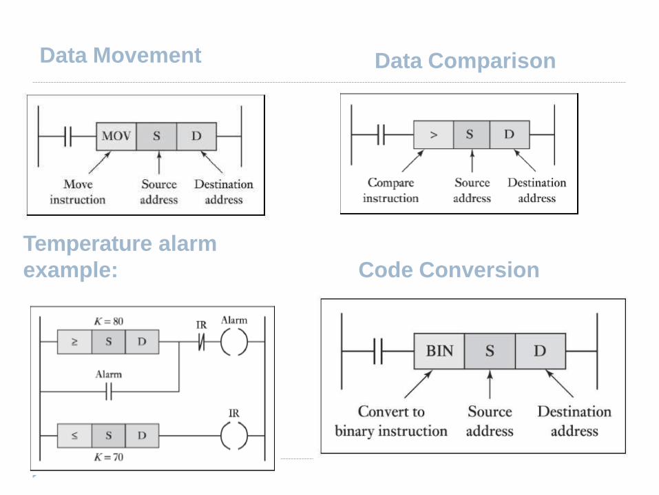
Data Movement Data Comparison
Temperature alarm
example: Code Conversion
SELECTION OF PLC
System (task) requirements.
* Application requirements.
* What input/output capacity is required?
* What type of inputs/outputs are required?
* What size of memory is required?
* What speed is required of the CPU?
* Electrical requirements.
* Speed of operation.
* Communication requirements.
* Software.
* Operator interface.
* Physical environments.